


Captain Obvious
Free Member
-
Joined
-
Last visited
Everything posted by Captain Obvious
-
 I need one hatch vent. One of these: Anyone got an old one they could part with. I don't care if the mounting pins on the back are intact or not. I'll just glue it on at this point! ☺️
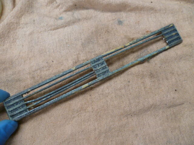
-
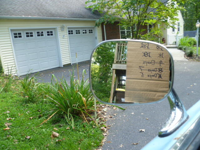
I drove out to a buddy's place today. I've got about 300 miles on him so far. Day five is behind me:
-
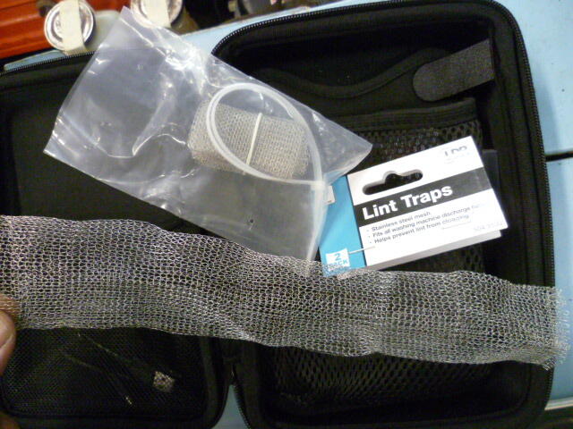
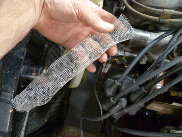
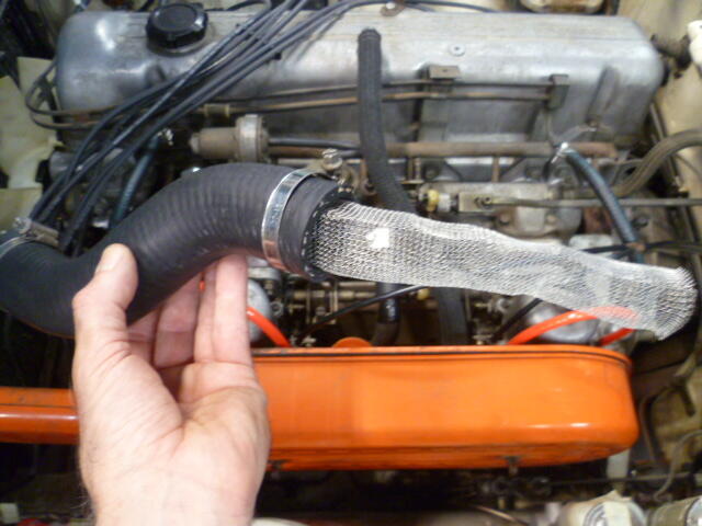
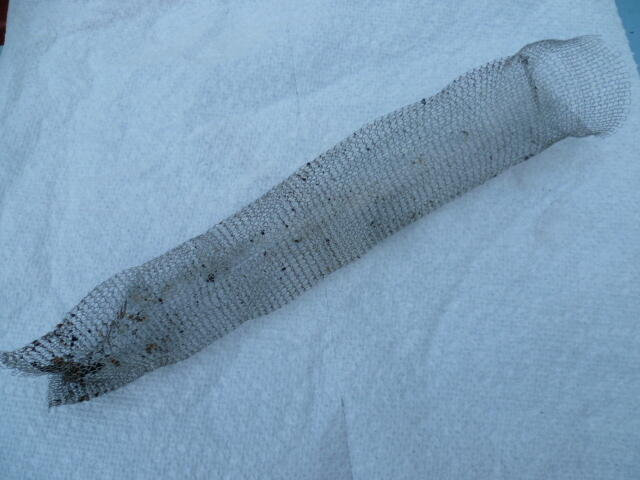
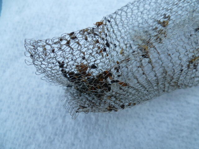
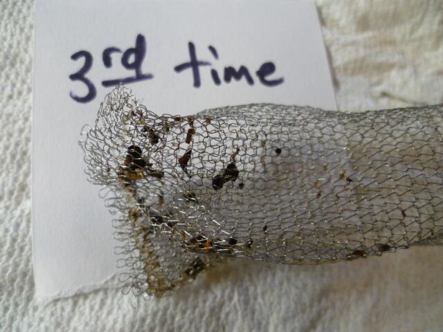
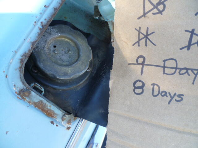
It's a pumpkin (or some kind of squash) seed and a bunch of other small seeds. Apparently that can happen when you store your car for years with the radiator cap off. I don't know what was living in there, but it had quite a comfortable home. Here's some background history... I saw critter evidence junk in the radiator. Flushed out as much as I could with a hose. Drove the car. and the temps started out fine, but started to creep up the longer I drove. Drained the radiator looked in the top, and there was junk in it again. Apparently some debris was now circulating around the cooling system. So I pulled the radiator and dug/flushed/picked out as much debris as I could and put it back in. This time, however,,, No messing around. I installed a "filter" between the head outlet and the inlet of the radiator with the hope that it would catch debris coming out of the block before it got into the radiator. The filter was a metal screen sock that's used on your washing machine outlet so you don't dump lint into your plumbing. And it just so happens it fit's well into the radiator hose. Looks like this: Chain mail condom: Stuff it into the top radiator hose: Drive around for a couple minutes and I catch this debris before it gets back into the radiator: Rinse and repeat. This is the third time I cleaned out the filter. Probably an hour of engine run time. The amount of debris getting caught is decreasing: I've since pulled it a couple more times and it's almost clean. I can probably remove the filter at this point.
-
I hit 70 mph today. Seemed to like it just fine. Not sure how it would like it for ten hours, but it seemed to like it for five minutes. Temps started creeping up a little, which is somewhat disconcerting since it was a cool evening. I have previously been through a (critter induced) radiator calamity, but was hoping it was mitigated to the point of being OK. Maybe I still need to do more... Running out of time!!!

-
Roo, Awesome. Thanks for checking, and I'm pleased that it is flat side up. I've tried both, and it fit's better flat side up. So despite the fact that it may "look better" with the rounded side up, I'm happy that it's actually supposed to be the other way.. Thanks again!!
-
So today's question... The grommet in the original shift boot is not symmetric. It has a flat side, and a more rounded side. Which way was it originally installed? I've seen pics of original boots that seem to show the flat side up, For example, here's a pic of an original boot and a reproduction (made number of years ago by a member of the forum): And here's one from Roo's recent thread about his 3-D printed shift knob: But I've also seen pics with the more rounded side exposed (up): So what say ye experts of the originality? What is the correct original orientation of the grommet? Here are the threads those pics came from: https://www.classiczcars.com/forums/topic/38329-shifter-boot-alternatives-anyone/page/2/#findComment-344979 https://www.classiczcars.com/forums/topic/69522-3d-printed-gearknob/#comment-678725
-
Thanks guys. I will jettison those two parts.
-
@Mike , There has been more spam added to the post by the bot.
-
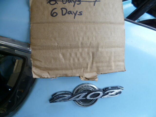
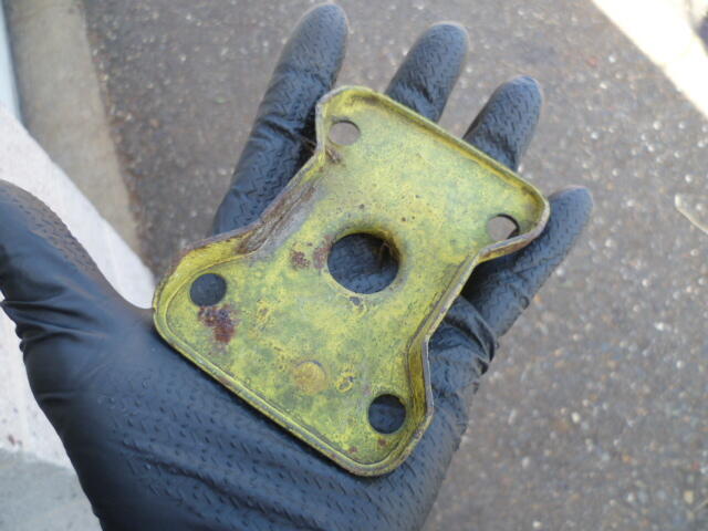
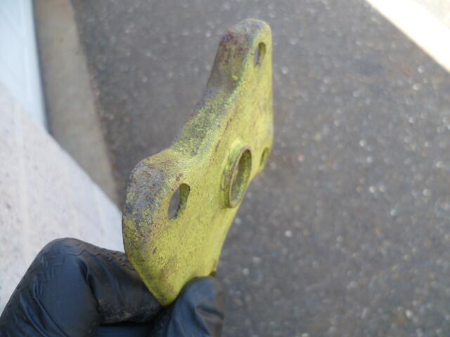
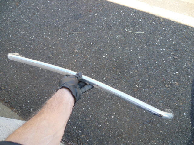
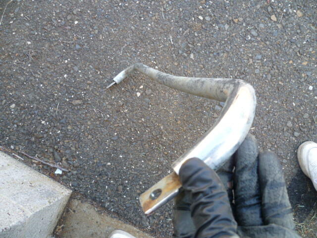
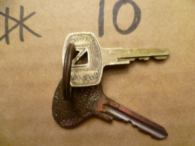
So I have a couple mystery parts. Not sure if they are Z related or not. Anyone able to identify these? Here's the first: And here's the second. Looks a little like an over-rider bar, but it's not:
-
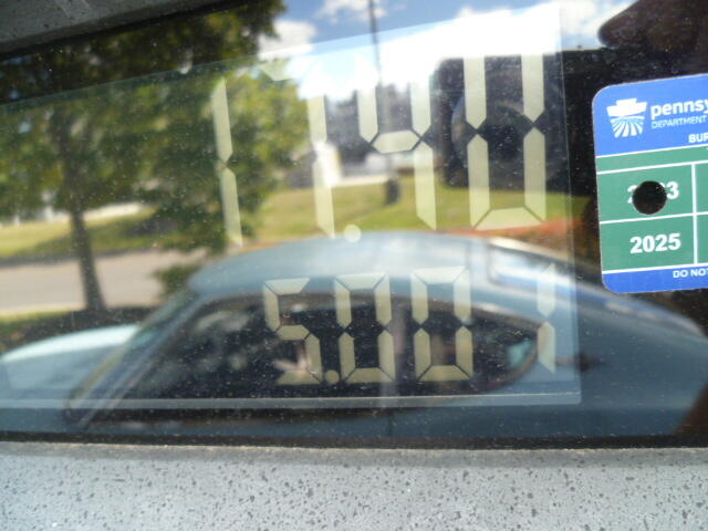
Today's event... I put more gas in him than I ever have before. I put five whole gallons in. And nothing seems to be leaking out!!! Proof!
-
Well in the time remaining, I may have to pick and choose what loose ends I leave drag. Hope your Dad would approve!!
-
Sure I'm open to suggestions!! The T/C rod stuff looks fine. They are snug and there is rubber in there. And about the locks... Early car single sided keys, and yes, he doors, hatch, and even the glove box work!
-
@Mike
-
I think we always lose control of it. All we can hope for is that science fiction is just that.... fiction. Star Trek ("The Ultimate Computer" for example) Matrix Terminator I Robot Ex Machina
-
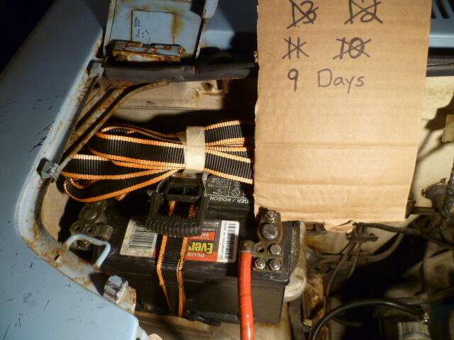
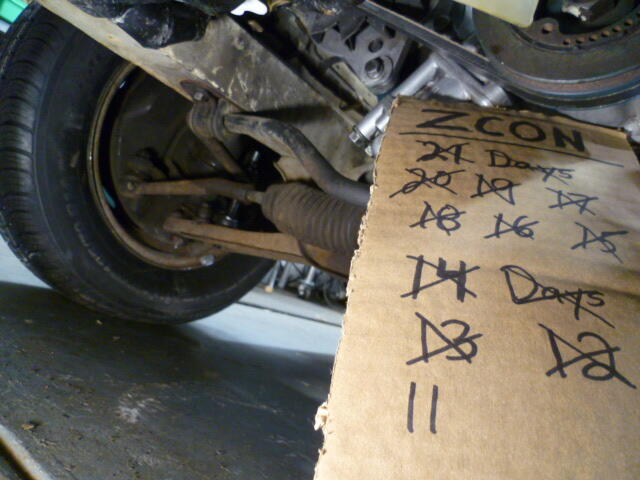
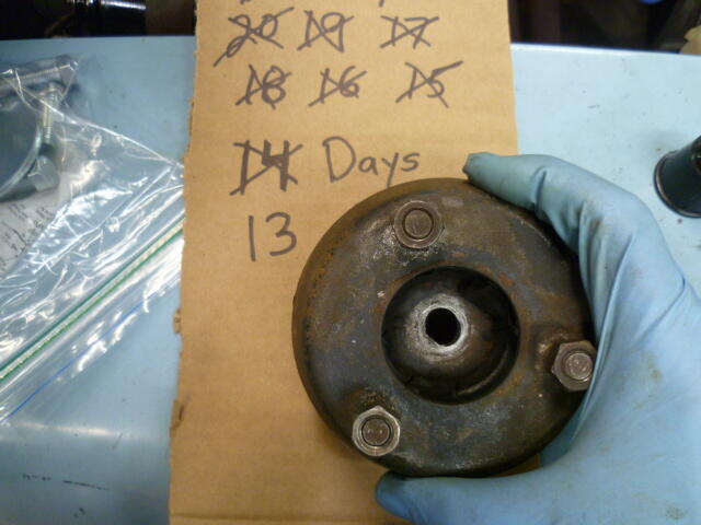
Countdown!!
-
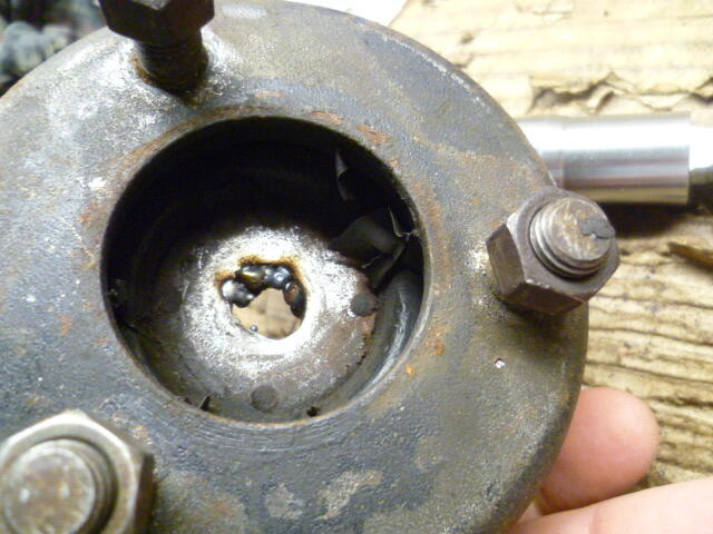
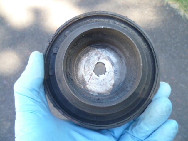
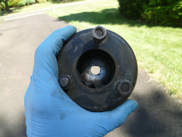
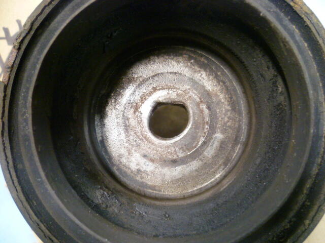
So with the help of some kind generous people from here on the forum, the front struts are back in the car! Here's a recap... I "welded" a couple dots down inside what was left of that "D" shaped hole. Isn't pretty, but doesn't have to be. All it has to do is keep the strut insert shaft from spinning while you tighten the nut. Hard to weld down inside that pocket, but here's what I did: Then I filed the hole back into a "D" shape and ground off a little bit of excess proud of the surface, and in the end, I have this: When you get the contrast right with backlight, you can get a decent look at the "D". Remember, all it has to do is keep the shaft from spinning: So with that crisis averted, put the struts back together. Put 'em on the car, reassemble and bleed the brakes, and I'm back to where I was two weeks ago*. Hahaha!! * But now I have struts that work.
-
Hahaha!! I'm hoping it won't come to that! ☺️
-
I thought I had pics of both flasher units (turn signal and hazards), but I can't find them. Memory says there are markings on the outsides of the cans that indicate how many filaments each one is designed for.
-
I wasn't there when they designed it, but my assumption would be the difference in the load that the two flasher units see. The turn signals are flashing four filaments (three in the rear and one in the front). While the flashers are seeing twice that (six in the rear and two in the front). The "off time" portion of the flasher unit is predominantly controlled by the load attached to the flasher unit. If that load is too small (like using LEDs), the off-time will be.... forever. If that load is too large, the off-time will be too short and the on-time will also longer than intended. The point is... The flasher needs to be matched accordingly to the load it is being used to control.
-
So I've been working on struts. Had a hard time getting the second one apart. Strut shaft kept turning in the "D" shaped hole. Got it apart and found this: Hoping I can dot a couple weld lumps in there to mitigate that issue. More news as it develops.
-
Thanks for the recommendation. I think my wipers work. My current plan is it's not going to rain while I'm on the road.
-
I've been maintaining a wiring diagram for the early cars. It's currently version 8, and you can find a copy here: https://www.classiczcars.com/forums/topic/69026-1970-wiring-diagram/page/7/?&_rid=23457#findComment-676548 It's not large or laminated, but it's accurate.
-
That is the accessory relay. On my mid-1970 car, that accessory relay sends power to the rear defroster and the heater blower. I don't know how frequently they were making changes to the wiring system, but I suspect your 1/71 is the same. Does any of that info matter to your turn signal issue? No. Haha!! ☺️
-
With the additional pics, I stand by the assessment that it's a Fall 1970 car with a rolled over odometer. It'a no "survivor" requiring a minor wash and buff. It's got all the wear and modifications and aftermarket parts that are typical with such a car. Oh, and a poorly applied re-paint. The annoying part is that the seller knows that some of the major claims in his listing are false. And he hasn't changed it. I do think, however, if he cleaned it all up and took copious good quality pictures, it would do better. As it sits, I don't think it's going to sell. And I think the seller knows it. I think at this point, it has become a test. Just to see what happens. If I didn't know better and bought that car, and then found this thread later?? Man, I'd be upset.
-
Hmmm... Seems like it should be worth at least as much as the 10/70 "project" 1971 Datsun 240Z Series I Project that was on BAT a couple weeks ago. https://bringatrailer.com/listing/1972-datsun-240z-359/ That one went for over $13K with a non-matching engine and poorly installed replacement floor pans. I'm thinking If that "barn find" thing on ebay has the original engine and floors, it should be worth more than the one that went on BAT?


