


Captain Obvious
Free Member
-
Joined
-
Last visited
Everything posted by Captain Obvious
-
 If everything is working as intended, then pushing coolant out into the overflow bottle is not only "not a problem", but it is actually a good thing. There should always be some coolant in the overflow bottle and the level should actually change as the engine heats up and cools back down. When the engine heats up, it pushes coolant out into the bottle, and then when the engine cools back down, it should suck the same amount of coolant back into the engine. I'm actually more concerned that your bottle was ever completely dry. That should not be the case.
 -
The active ingredient in that stuff is "HYDROCHLORIC ACID 7647-01-0 10-20" I wouldn't put that stuff in my aluminum headed Z motor. Especially hot.
-
That bracket attaches to the dash metal skeleton and provides the mounting points (two) for the underside of the HVAC system. It kinda completes the bottom edge of the "box" around the HVAC controls. It runs (in "U" orientation) between the HVAC control panel and the radio, It is not shown in the parts breakdown above and it has nothing to do with the console or the radio. In fact, if the center console is removed, that bracket stays with the dash. It does not come out with the console. Having a hard time describing that thing with words, so if that's not good enough, let me know and I'll snap a pic.
-
I don't know what they used back in the day, but last time I looked the label today says citric acid.
-
Didn't break any old brittle plastic in the process?
-
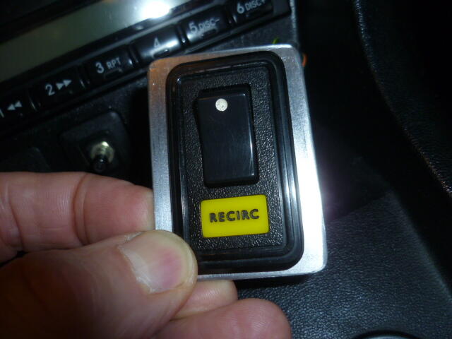
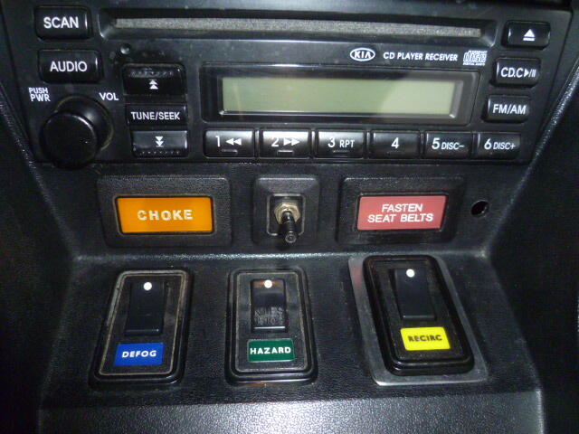
The one marked "DEFOG" still controls the rear defroster. I wanted to combine the blue DEFOG indicator lamp with the switch so that would open up the spot above the switch. That way I could put the CHOKE indicator where the blue defog indicator was originally. I intend to run a carb conversion on my 77 sometime (when I finally get around to it). And the switch on the right marked "RECIRC" controls a fresh / recirculated servo motor on my HVAC system.
-
I took some pics of the kind of stuff I've been messing with... Here's my thin steel adapter plate the I'm using to mount a stock shaped switch on the far right console hole. Note that for the pic, I didn't want to pull the whole console out to take out the switch, so that's why the wires are running through the adapter plate. Also note that I intend to paint the plate black, but I haven't gotten around to that yet: And here's the switch that I'm putting in that location: This is what my switches look like at this point: And with the switches ON:


-
I would not try to stake them. The risks are just too high. I would use the loctite.
-
Last knob I had that problem with, I filled the inside with RTV silicone. Changed the weight and I think the elastomeric properties of the silicone helped damp the resonance.
-
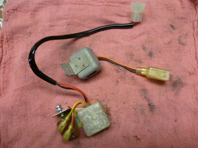
When you remove that resistor from the harness, you completely separate the tach from the ignition circuit. With that resistor out, the RPM input signal to the tach is open circuited. That's why the tach didn't work at all when you pulled that resistor. That said though... It really is important that the original ignition module be disconnected, so double check just to be sure.
-
Ferg, Did it look "stock-ish"? I've always thought of putting a switch there, but I've never seen anything that looked like it really belonged. I want something that looks like it could have come from the factory.
-
Your switches look good. I haven't finalized my situation, but I'll try to snap a couple pics when I get the chance. I warn you though... It's going to raise some questions.
-
(I think the reason Dave asked is that) sometimes the shift knob can amplify vibrations and make a buzzy noise. You can check if it's part of the problem by simply unscrewing it and seeing what (if anything) happens to the noise.
-
LOL!!
-
Wait. Are you saying I'm fat?
-
Here's a thread with some stuff that might help. https://www.classiczcars.com/forums/topic/57671-electric-servos-instead-of-vacuum-driven-hvac/ The pics are dead, but if there's something you want, let me know.
-
Glad to help. I don't think you'll crack any plastics taking that panel out. The more risky maneuver is putting it back in. Don't torque the mounting screws too tight. I've seen a couple of those panels with cracks radiating out from the mounting screw holes due to being tightened too much.
-
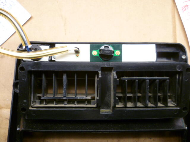
The map light is replaced from the back side of the vent panel. Four screws to take the panel off and then the bulb goes into the lamp from the rear. I think they may have changed some of the details over the years from 74 to the end, but here's a pic that should help. This is the back side of that map light panel:
-
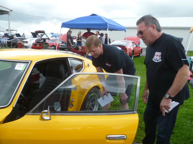
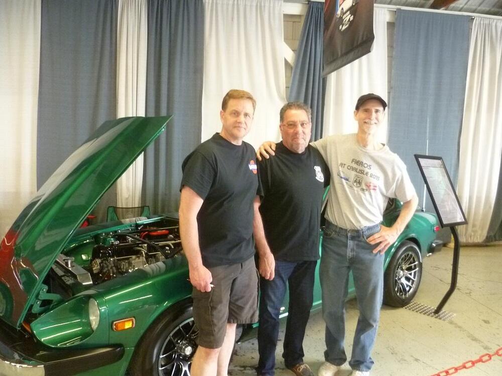
LOL!! Again? Haha!! Here's the (in)famous @Mike W and @GGRIII looking over GGR's first place winning 260Z. Yes... Gary's 260 beat out Mike's 260 for the first place spot. And nobody can convince me that it was as simple as the fact that Mike's beautiful Gold Cup Z was tucked safely parked inside one of the special display buildings (and most people didn't even know it was supposed to be considered for judging?). Veni, vidi, vici Oh, and I did mention that Mike has a beautiful 260 as well, right?
-
I think I'm headed out there tomorrow. Hope the weather holds!!
-
Haha!! Probably not, but of all the stupid stuff I do, I'm less worried about those dollies than the rest of the stupid stuff. And the rating on the small moving dollies is 1000 pounds each. Now I don't trust the absolute validity of that rating, but it's about twice what you would be putting on it with a corner of the Z. So there is a significant overrating.
-
I have a pair of the vehicle dollies as well, but no... They do not raise the car nearly as high as the moving dollies with a couple slabs of wood on top. And... I'm not sure which moving dollies you were looking at, but the small ones are currently $26 for a pair while a pair of those vehicle dollies you linked to are sixty bucks. So if you want them on all four corners, you can get four of the moving dollies for less than one pair of the vehicle versions. I also found that the moving dollies roll much easier than the vehicle dollies. Not sure why, but they just move a lot easier.
-
I jacked mine up and then set it back down on four small moving dollies (from HF). Lifts the car up high enough to be able to get under it and also allows the suspension to squirm around to neutral position which is important when tightening the suspension bolts. Put a plank or two of 2 x 10 across these: Don't let your car roll out into the street on the dollies.
-
Yes, those hoses are full of coolant and will gush some when you take them off. With that in mind, I would drain the coolant first to minimize the mess. There will still be some coolant coming out of the tubes even after draining the system, but probably less than if you didn't drain the system first. Oh... And when you're all done with the coolant leak repair, I would disconnect the electrical connectors that go to the center console and clean them out. It's common for those connectors to be green crusty corroded due to heater system leaks over the years getting inside the contacts and sitting wet and festering.
-
Well before you go bending stuff, I think it would be important to know if someone had been in there before messing around. Can you / could you tell if someone had been into the AFM before you?


