


Captain Obvious
Free Member
-
Joined
-
Last visited
Everything posted by Captain Obvious
-
 Wow... "HoldPeak" meters, huh? So they get to use the abbreviation HP in all their products and model numbers? How convenient.... "For more than a decade, We specialize in R&D, design, production, sales of the digital measurement instrument meter. At present, our products have been exported more than 80 countries and areas around the world, and we established a complete set of after-sales service in Europe, the United States and Australia"
 -
Not for the fuel pump. The pump is on the other side (the front side) of the axles. I don't know what that is. My PO must have removed that. My only thought is an anti-puncture shield between the tank and the head of the bolt that holds the rear control arm in? Problem with that theory, is there isn't one on the other side...
-
Hahaha!!!
-
Yes. The change to the different length float valves coincided with the introduction of the 3-screw round tops. In other words... The earlier (70-71) four screw round tops used the same float valve in both carbs. The later (72) three screw round tops used different lengths between front and rear.
-
Oh, and make double dog sure you get all that grinding grit cleaned up before it gets inside your engine.
Glad you got the pump off without damaging anything other than the pump. Good work with the grinder. 220. 221.... Whatever it takes. So about the Melling pumps: The M90 is for the manual trans cars without a turbo. The M152 is for the manual trans turbo cars and it has the same pressure limit as the M90, but it pumps higher volume.* The M111 is for the AUTO turbo cars. It has not only higher volume, but higher pressure limit at the top end. Even though my car is non-turbo, I'm running the M152 in my car. Works great in my tired engine with worn old clearances everywhere. * They achieve the higher volume by using longer rotor gears in the M152. About 20% longer maybe? I've got pics if someone really wants to see it.
Excellent! Yeah, once you know where the tricks are, it's not that bad. Glad you got it out!
Haha!! True that, my friend! I lubed the bolts well with anti-sieze when I put it on. Hopefully I won't have to resort to that ever again!
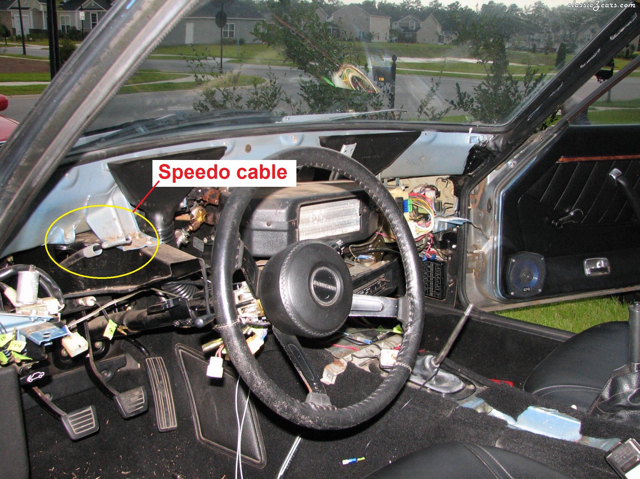
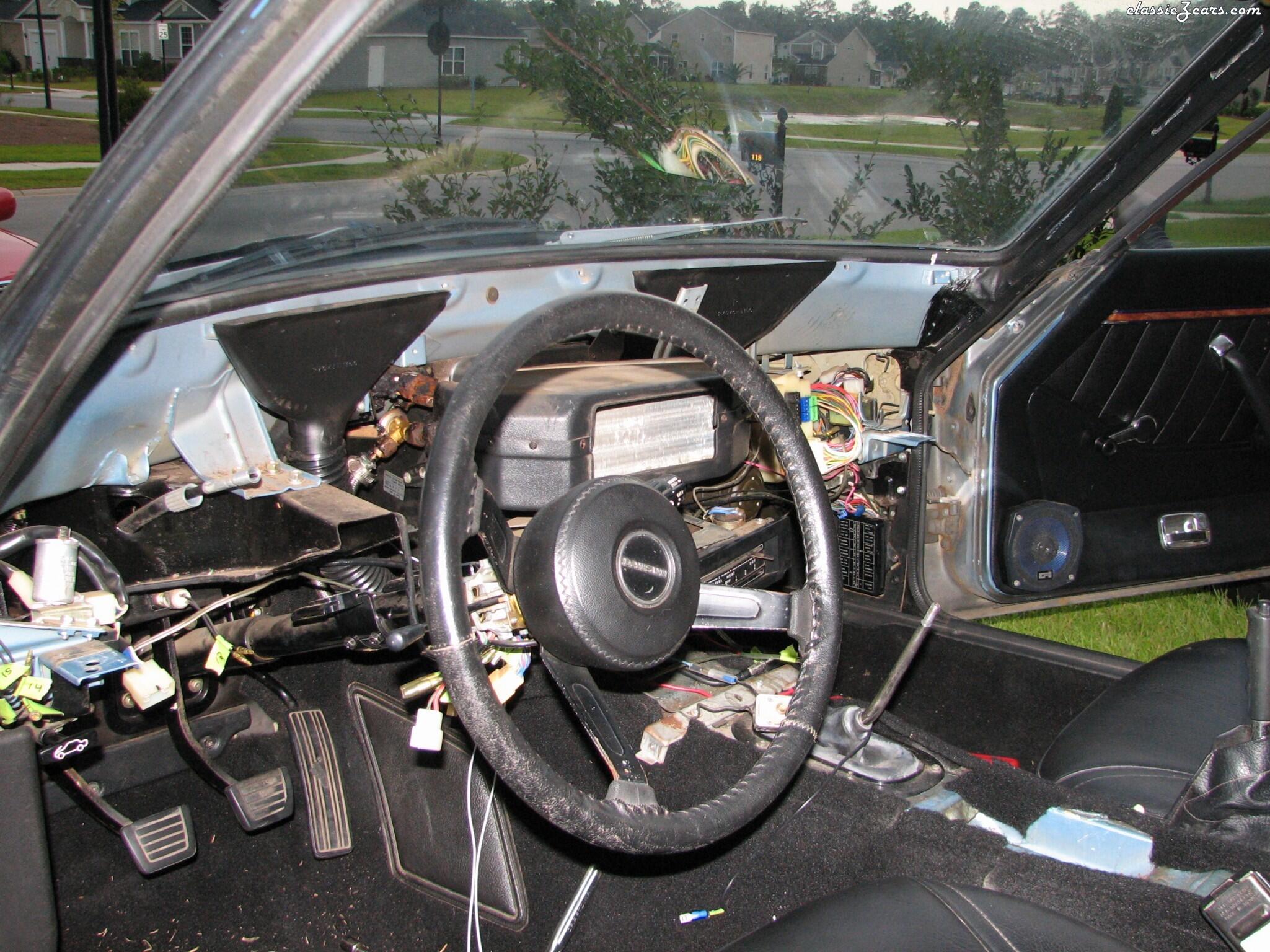
Here's two more pics. This is taken looking at the back of the speedo after the dash has been pulled out: And this is the same pic from above, but I circled the cable and threaded coupler hanging loose: Good luck!
 I would start simple... Are you sure they aren't stock with overspray from a previous paint job? And if for some reason you are convinced that they are aftermarket, I would start simple... Which of the aftermarket versions are constant pitch (not variable rate) and are long enough that they don't leave a gap when the strut assy is off the car like in your pics. Some of the aftermarket stuff is so short that it results in a gap when the wheels are left hanging. It doesn't appear to be the case with what you have there.
I used Melling as well because I liked the cast iron body instead of aluminum. But if you don't care about that, you can get an original Hitachi style (aluminum body) version from Rockauto for less than thirty-five bucks.
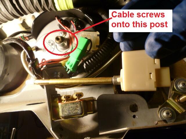
There is a cable that connects to the transmission. A mechanical cable, not an electrical one. Internal cable rotates inside an outer jacket. This mechanical cable spins when the car is moving and provides the "speed of travel" input to the speedo. Big metal cable right in the center of the back of the speedo. There is a large (15mm) white plastic collar that screws onto the back of the speedo to hold the cable to the housing. It is possible to remove the speedo from the dash first, but it's not necessary. But if you want to do it that way, here's a pic that might help? And here's a pic with the dash removed. Note that you have to take the two steering column bolts completely out and let the column hang down enough to get the dash out from above it:
I would start simple... Are you sure they aren't stock with overspray from a previous paint job? And if for some reason you are convinced that they are aftermarket, I would start simple... Which of the aftermarket versions are constant pitch (not variable rate) and are long enough that they don't leave a gap when the strut assy is off the car like in your pics. Some of the aftermarket stuff is so short that it results in a gap when the wheels are left hanging. It doesn't appear to be the case with what you have there.
I used Melling as well because I liked the cast iron body instead of aluminum. But if you don't care about that, you can get an original Hitachi style (aluminum body) version from Rockauto for less than thirty-five bucks.
There is a cable that connects to the transmission. A mechanical cable, not an electrical one. Internal cable rotates inside an outer jacket. This mechanical cable spins when the car is moving and provides the "speed of travel" input to the speedo. Big metal cable right in the center of the back of the speedo. There is a large (15mm) white plastic collar that screws onto the back of the speedo to hold the cable to the housing. It is possible to remove the speedo from the dash first, but it's not necessary. But if you want to do it that way, here's a pic that might help? And here's a pic with the dash removed. Note that you have to take the two steering column bolts completely out and let the column hang down enough to get the dash out from above it:
 Only if we knew how fast he was removing the oil pump.
Been there, done that. Oil pumps are cheap. Front covers are not. There's no way you want to put a used oil pump of questionable integrity on your newly reconditioned engine. Sawzall is your friend.
You do not have to remove the tach or the speedo to pull the dash. You do have to unscrew the speedometer cable from the rear of the speedo, but I've always been able to do that relatively easily with the speedo in place. Just reach your arm up behind the speedo and unscrew the coupling. As for what it is that's holding your stuck dash in place, not sure. I used to have a list around here somewhere for what was necessary... I'll look for that list and see if I can find it.
One additional thought... How about making it the same accent color as the rear taillight panels and the grill, etc? That wouldn't directly blend with the color and texture of the console plastic, but it would tie in well with the other accents around the car.
Haha!! I've seen wrinkle finish, and hammered finish. And I think I've also seen something that looks like it has sand in it... Like a traction finish for stair treads or something? Good luck with the experiments and hope you come up with something you like. What's on there now? Semi-gloss?
That's what I would do. I wouldn't do it with the engine running though. I would shut it off first.
Looks cool, but I'm having a little trouble reconciling this: I think you're way beyond having it "blend". I mean. c'mon... Fancy laser cut script lettering with a flashy gold background. With LED readout and a row of shiny chrome switches. And you're wanting it to blend? Hahaha!!
Glad to help. Just remember that simply knowing where they go is only half the puzzle... Figuring out which one goes where is the other half. Some (most?) of them are relatively easy to figure out, but if I remember correctly, some of them can be a little tricky!
Yes, that's exactly what I meant. Thanks for clearing that up!!
Not that it matters (other than to satisfy my pedantic nature)... It wasn't just the 280's. The 260 also used plastic. If S30 doesn't turn anything up, I've got a spare pair here.
2 for fuel banjo inlet 1 for bowl air vent nipple 1 for bowl drain plug (later round tops only) 1 for needle valve 1 for damper stalk 1 for inside chamber to cushion piston end of travel As for the last one... Not sure. On the four screw round tops, there might be a seal between the nozzle holder and the bottom of the main carb body? Don't remember for sure.
Only if we knew how fast he was removing the oil pump.
Been there, done that. Oil pumps are cheap. Front covers are not. There's no way you want to put a used oil pump of questionable integrity on your newly reconditioned engine. Sawzall is your friend.
You do not have to remove the tach or the speedo to pull the dash. You do have to unscrew the speedometer cable from the rear of the speedo, but I've always been able to do that relatively easily with the speedo in place. Just reach your arm up behind the speedo and unscrew the coupling. As for what it is that's holding your stuck dash in place, not sure. I used to have a list around here somewhere for what was necessary... I'll look for that list and see if I can find it.
One additional thought... How about making it the same accent color as the rear taillight panels and the grill, etc? That wouldn't directly blend with the color and texture of the console plastic, but it would tie in well with the other accents around the car.
Haha!! I've seen wrinkle finish, and hammered finish. And I think I've also seen something that looks like it has sand in it... Like a traction finish for stair treads or something? Good luck with the experiments and hope you come up with something you like. What's on there now? Semi-gloss?
That's what I would do. I wouldn't do it with the engine running though. I would shut it off first.
Looks cool, but I'm having a little trouble reconciling this: I think you're way beyond having it "blend". I mean. c'mon... Fancy laser cut script lettering with a flashy gold background. With LED readout and a row of shiny chrome switches. And you're wanting it to blend? Hahaha!!
Glad to help. Just remember that simply knowing where they go is only half the puzzle... Figuring out which one goes where is the other half. Some (most?) of them are relatively easy to figure out, but if I remember correctly, some of them can be a little tricky!
Yes, that's exactly what I meant. Thanks for clearing that up!!
Not that it matters (other than to satisfy my pedantic nature)... It wasn't just the 280's. The 260 also used plastic. If S30 doesn't turn anything up, I've got a spare pair here.
2 for fuel banjo inlet 1 for bowl air vent nipple 1 for bowl drain plug (later round tops only) 1 for needle valve 1 for damper stalk 1 for inside chamber to cushion piston end of travel As for the last one... Not sure. On the four screw round tops, there might be a seal between the nozzle holder and the bottom of the main carb body? Don't remember for sure.


Important Information
By using this site, you agree to our Privacy Policy and Guidelines. We have placed cookies on your device to help make this website better. You can adjust your cookie settings, otherwise we'll assume you're okay to continue.