Captain Obvious
Free Member
-
Joined
-
Last visited
Everything posted by Captain Obvious
-
 And I'm probably going to end up with a generic powder fire extinguisher. Yes, they are messy, but they're so ubiquitous and easy to get. I'm thinking if things get dire enough that I have to use it, the last thing I'm going to be concerned with is the mess.
 -
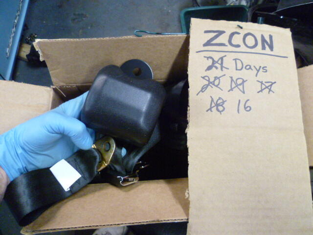
Still don't have the strut fiasco solved yet, but seat belts arrived!!
-
Yeah, there was something wrong with the forum. Wasn't working properly, but it seems to be back now.
-
Exactly. I'm not bemoaning the good deed that I did, but the delay is really putting a damper on my shakedown time!
-
Nothing special. Just KYB gas. The really silly part is that I HAVE a set of KYB's here already. The plan for them was to put them on my 77 280 as part of a project I have planned for that car. But since I was working on this 240 and running out of time, I figured I would use those KYBs on the 240 and then buy another new pair when I was ready to move forward with the 280 work. So.......... I tear the 240 apart. Break one strut down and get the old cartridge out of it. Open the KYB box I have here, and......... There inside the KYB box is a note. In my own handwriting. I sent the small gland nuts to another Z guy some couple of years ago because I wasn't going to be using them. I need the big ones for the 280 and I didn't own a 240 at the time. The small gland nuts were surplus to me and someone else needed a pair. So I sent them away. Aaaaaaarrrrrghh!!!!!
-
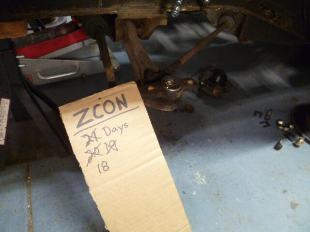
Countdown continues. I'm still waiting for struts. Not ideal. I need to get more miles on this thing to see what else falls off before I drive 1000 miles!!!
-
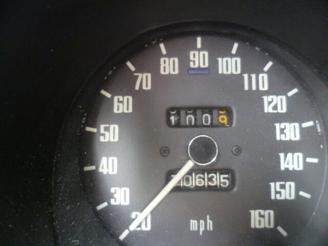
Countdown!! I got 100 miles on it: And those 100 test miles made it clear that I need front struts:
-
Sticky pistons on 4-screw round tops. Not ideal. About the only things that would account for that would be a) severely misaligned nozzles underneath or b) mismatched domes/pistons. You can check for the mismatching between the domes and pistons by taking the domes off, pulling the pistons out of the carbs and then sliding the pistons into the domes and see if they move smooth and free (while the dome and piston are in your hand, not mounted to the carb body). And you can check for misaligned nozzles/needles by either removing the needles out of the pistons, or by loosening up the nozzle alignment nuts on the under sides the carbs and seeing if the pistons move free while the nozzles are way loose.
-
Hope everything is dry now and your leak is all fixed up!
-
Sometimes new seals come with some little dabs of lube already on the inside lip. If yours did not, you can just use motor oil, or my favorite... silicone grease. As for the outside surface, I would do the same there. Motor oil or silicone grease. I wouldn't use anything that sticks like the aviation permatex. In my experience, the outside of the seal has significant interference with the hole you press it into. In fact, I've had to hit them harder than I was comfortable with just to get them seated into place. If your experience is like mine, you'll be thankful for the slippy on the OD, not the sticky. Use your old seal as a protection ring to tap your new one into place. And make sure the new one is square when you are done.
-
I wouldn't have any problem reusing that clutch. I'd replace the seal and reuse everything else. Don't forget a little bit of new EP grease on the pilot bushing.
-
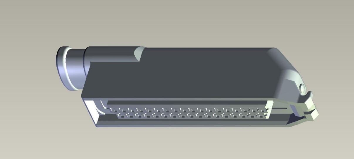
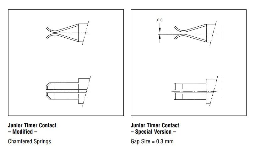
Have you started to identify which contacts they used inside the shell? There are lots of different members within the family, and I'm not sure which ones they used. They are the split finger version and are not gold plated... Those two things you can tell from just looking into the connector. But beyond that, I haven't looked into it. And also within the family... There is JT (Junior Timer), and JPT (Junior POWER Timer), I believe the major difference is the inclusion of a spring (on the power version) to clamp the female contacts closed tighter. So if you're concerned with contact force, maybe you could "upgrade" a couple contacts to a JPT version instead of the original JT? Not sure it's even possible, but just a thought.
-
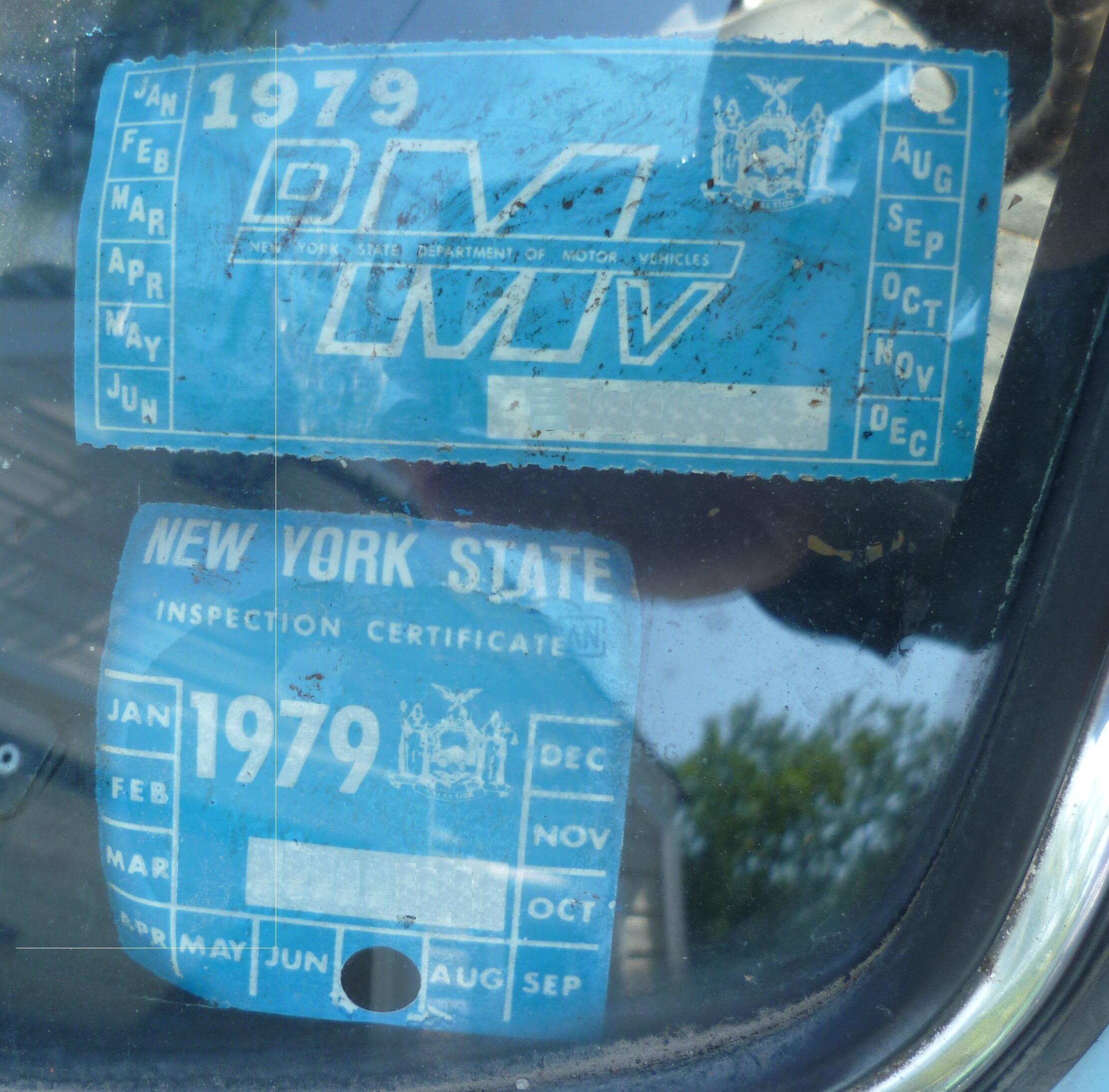
Mine is a July 1970 and I believe it languished since........

-
Thanks for the tips on the seat belts guys. So for the Wesco Roadster seat belts... What length buckle end did everyone use? Everyone use the 11 inch version? And any input for a fire extinguisher style?
-
Philip, It's so good to hear from you. I think of you and Janet often. Please reach and get in contact when you're feeling up to it.
-
I haven't seen the gasket separately. but if the whole connector shell is only a couple bucks, why not buy one and strip out the gasket? Couple pics to go with your text above. The red oval seal is what you're looking for, right? And these are the plastic retainer strips you mentioned maybe?
-
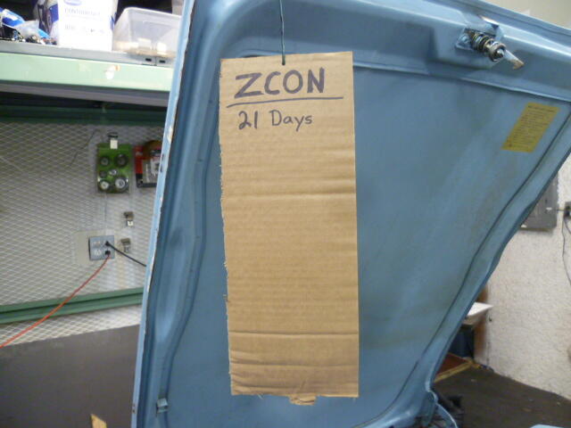
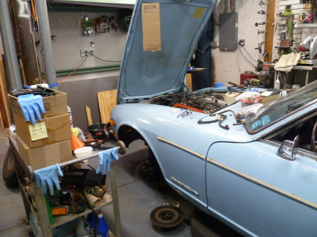
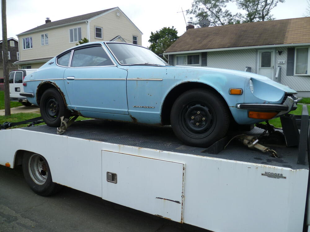
So I've been working in the shadows on the reanimation of an early 240Z. This is not so much a restoration, but more of a reanimation project. Reanimation of an lifeless vehicle with a focus on originality. The OG 240Z: This car hasn't been on the road for decades. Many decades. And in the end, he won't be pretty, but he'll be back on the road. So let's start with the immediate... My intention is to drive this Z to the upcoming ZCON in Nashville and there are a couple things I need advice on before the trip: First, I need to carry a fire extinguisher and I know nothing about them (other than they are supposed to put out fires). Anyone know the system and have a recommendation for which type would be best for automotive related incidents? Second, I've got the original seat belts in the car, but they are the early non-adjustable style. I'd like to install something newer, safer, better, easier to use before the trip. I might swap the originals back in once I get there, but for almost 1000 miles on the road, I think I want newer technology. Is there an easy to drop in system for the 240Z cars? ZCON or BUST!!!
-
-
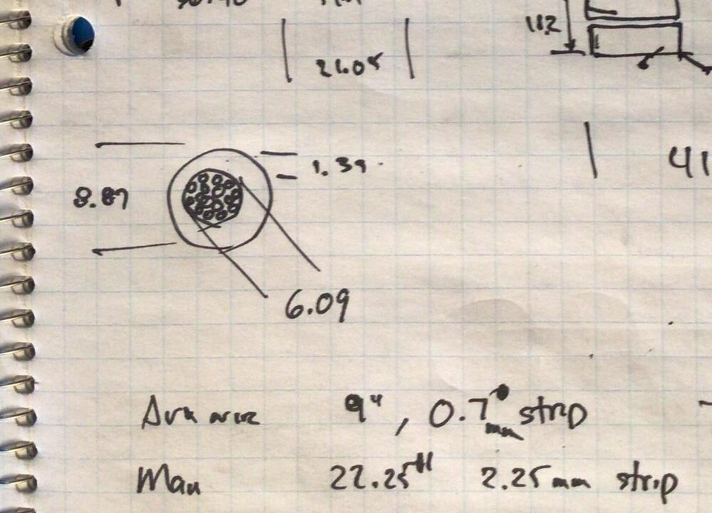
That would be great. Here's a clip from zKars notes. if I'm understanding the drawing correctly, he measured the wire diameter at 6mm (.24inch) and the insulation OD at about 9mm (.35 inch). I'm finding gauge numbers and wire diameters all over the place and am just looking for something similar.
-
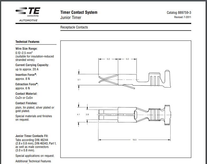
I think you would be surprised at the low amount of insertion force required to mate one of those female contacts onto the male tab. They do that on purpose because by the time you get to 35 of them, it adds up. So if you aren't 111% sure that you have a contact issue, I might keep investigating. But if you are looking to replace some contacts, i believe everything involved is old Amp (became TE) "Junior Timer" series. JT. There are many different categories within that family, but I believe the contacts used on the harness side are specially designed to be a lower insertion force. And yes... there should be a retainer tab on each contact. You should not have to worry about all the contacts come flipping out by accident. I think. ☺️

-
So... While we're here. Anybody have an educated guess as to the gauge of wire used in the original cables? The common choices here in the US are 4-gauge, and 2-Ga. You can get others, but those two are the most common.
-
There goes Roo again showing off his ebay prowess. Your kung foo is the best.
-
-
-
Well, certainly if you see something pop up for brake master guts, I'm all ears. There's one guy on ebay who has them, but I'm struggling with the price. I'm not sure if the master I have here would work even if the guts were new. I'm not digging the idea of spending over $100 as a gamble just to see if it works. And I wish I could help you with the wire clamp details, I've got original clamps here, but they are all aged to the point that it's quite doubtful I could tell what color they were when new.