Captain Obvious
Member
-
Joined
-
Last visited
Everything posted by Captain Obvious
-
 First, some answers... For the 71 four-screw lids, You should be using the 18.5mm long valves. So what you are using there sounds fine. The target float level for the 71 lids is 20mm below the lid, but I believe anything close (18-22) should be fine. When I went through the same thing, the only solution I could come up with was to add weight to the floats. This 4g brass plug threaded into the side of the float worked well:
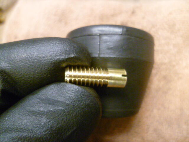
-
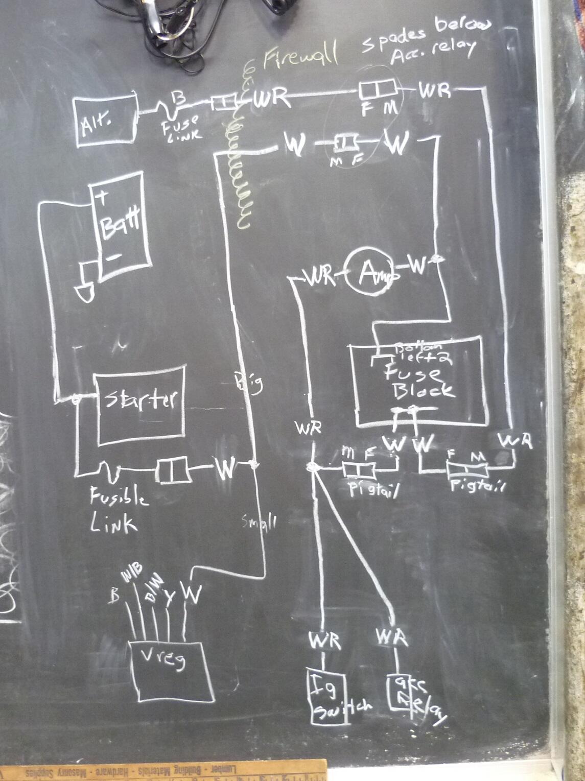
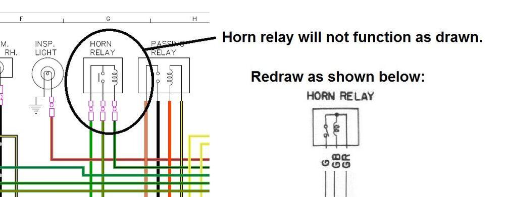
Thanks Chas. I looked through my pics and don't have anything good, but I believe the three connections to the antenna switch are three independent spade connectors on three loose wires. I'll confirm when I get a chance unless someone beats me to it. I'll work on the "vintage" style diagram and you can work up the "new style color" version. Might just be me, but I'm finding working on an early car is enjoyable using an early wiring diagram. Cleaned up and corrected, of course. Kinda quirky. So how would you like me to communicate mistakes on your diagram? Screen shots? For example, like this:
-
Thanks Steve. I'll make that clear on my wiring diagram when I'm making the next batch of changes.
-
And I have a question... On a future revision, I'm intending to clearly show the coil and ballast resistor on the engine side of the bulkhead firewall. But what about the reverse light switch. Do the wires going to the reverse switch on the transmission go through the same firewall bulkhead out towards the engine, or do they go through a hole somewhere else? I haven't looked for those on my car, but hoping someone here knows off the top of their head.
-
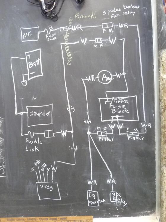
Glad you're still around! I spent some time looking at the details of the power distribution system and cobbled up this sketch: And I made some changes to the wiring diagram I've been messing with. Here's the latest: <V3.0>
-
Here's the latest. I swapped the gauge locations and made a couple other small changes. Please let me know what you think: <V2.0>
-
@Namerow So independent invention... Here's what I've been messing with. I cleaned up and modified the diagram from the BE section of the FSM. Biggest changes are adding the accessory relay and it's associated devices (heater blower and rear defroster). Lots of other smaller changes, most of which you identified in your notes. I will make additional changes based on stuff you found that I did not such as the incorrect labeling of the gauge functions (didn't see the forest through the trees) and it seems there are some issues around the combo switch area where documentation does not accurately depict reality.
-
Oh, and the existence / non-existence of the accessory relay... I was wondering if maybe that was a build date issue, But if you have the accessory relay on your 4/70, then even if it was added after initial release, it was added pretty early.
-
Namerow, So here's my assessment at this point... I should have asked earlier because I independently found most of the issues you noted on your markup. Asking sooner would have made that easier. Those issues are why I was expressing frustration with the documentation. One big issue, however, is your interpretation of the power going through the "F" fuse. That fuse feeds FROM the ignition switch, it towards it. The rest of stuff (turn signal flasher, and gauge power) is fused. And of course, that also means that the comment about the fuse block nomenclature is also incorrect when you said that top row are all power-out with the exception of "F". The entire top side IS power-out, including "F". And many of the problems I turned up still exist in the color version. Maybe @EuroDat can pop in here if he caught wind of this tread? This could be an opportunity to make that document better.
-
I found that exact situation when I was looking for a spare for my car. Now granted, I was limiting my search to donut space saver spares, but I had fitment issues with the front brakes. The little drums in the rear were fine, but I was hitting the caliper up front. And my car, being a 77, has the reduced size spare tire well. You don't have that complication.
-
What he said. Hope you found the root problem!!
-
Hmmm... Try one. It might be OK. The diameter should be fine. The only thing that might be an issue is the width, but in theory, you're less than .400 inches wider than stock. Maybe you're looking at a non-problem!
-
Thanks for the files. I'll look that stuff over and see how they look!
-
What he said. In fact, I wouldn't even deal with a tank... I'd just fill up the float bowls with a piece of tubing and a funnel. Round tops will run the engine for 30-60 seconds before the bowls get sucked empty. I would hope that your carbs would be in the same ballpark.
-
Just wanted to pop in and say glad to help.
-
Why won't a full size fit? I thought the 75 had the big spare well? They didn't change to the smaller spare tire well until 77.
-
Anyone got anything different than the above before I take one of those and try to make improvements? Clean it up and fix the issues I've found (when compared to the car I'm working on).
-
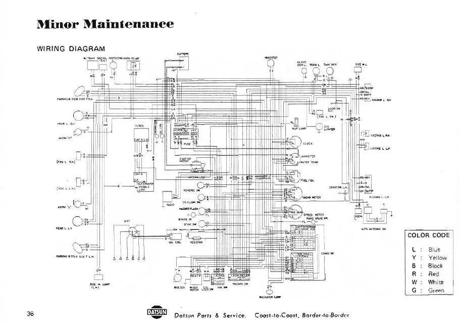
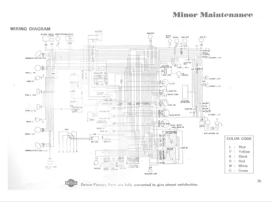
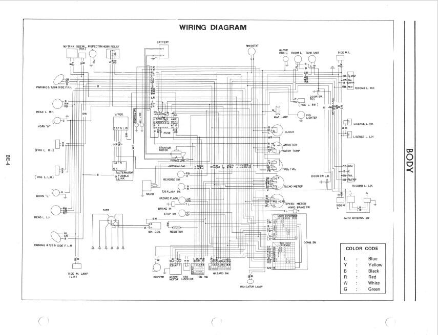
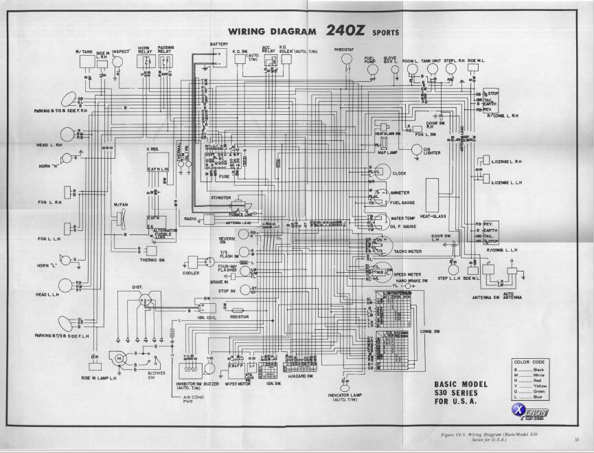
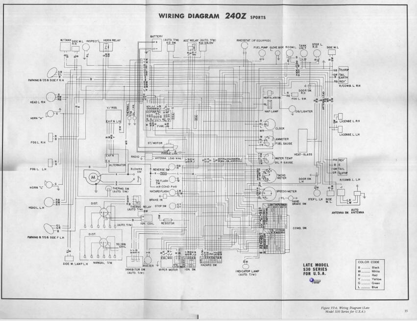
I've poked around looking for a wiring diagram for the early cars (1970) and haven't come up with anything really good. I've turned up five diagrams so far, and they all are questionable in accuracy. This is clipped from a 1970 owners manual: This is another version, supposedly from the owners manual: This is clipped from a 1970 Factory Service Manual - Body Electrical section: And here are two versions clipped from the Service Manual Supplement, which I believe came out for the 1971 model year:
-
Nope. Think about it like "the gas tank will spill over into" the vapor canister. It's not pulled to the tank. It runs over into. Thankfully, I don't smell gas fumes with my car ever. I've never messed with the vent hoses in the back by the tank, but I have no idea what (if anything) my previous owner did.
-
That's normal. The hose that leads to the gas tank is not directly connected to any vacuum source. Maybe try picturing it this way... The carbon canister is like a big open top bowl full of small rocks. No lid. And there are two tubes stuck deep into the bowl of rocks. One of those tubes goes to the intake manifold and the other tube goes to the gas tank. You can't ever pull a vacuum on the bowl because it's open on the top. There is no lid. There is a third tube involved, but that third tube doesn't go into the bowl at all. It just actuates a valve switch on the tube leading to the intake manifold. Not sure I'm helping or hurting at this point.
-
-
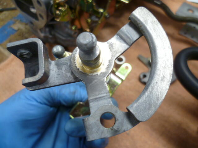
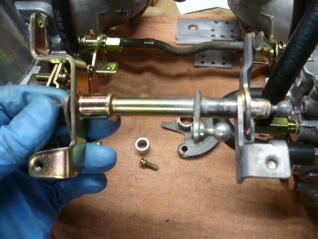
Really neat implementation. Certainly simpler than the complicated silver soldering thing that I did. So why didn't you just grab onto the original existing ball on the linkage? Is it simply that the Lokar* cable didn't come with the correct sized ball socket? * Ummm..... of the Hill People? Anyone?
-
Gotcha. That's not at all what my buddy got. Thanks for the info.
-
@texasz A local buddy of mine is having the same issue with a set of new headers he just bought. Out of curiosity, what headers are you using that caused you the interference with the shield?
-
The reason it doesn't thread in as far is probably because of the thread profile differences. NPT uses 60 degree threads, while BPT uses 55 degree "Whitworth" style threads. So while the pitch is the same, there are some minor differences in the shape of the peaks and valleys. That said... If you are working on one of the sizes where the BPT and NPT thread pitches actually lines up the same (some of them do and some don't) and you aren't intending to hold back a lot of pressure, you can usually get away with using an NPT plug in an application where the correct part is actually BPT. Put an extra wrap of teflon tape on it and crank it in. Of course, the right thing to do would be to source a BPT plug.