


Captain Obvious
Free Member
-
Joined
-
Last visited
Everything posted by Captain Obvious
-
 I've been inside a non-turbo 83 ECU, and it was, in fact, computer controlled. They were running a Hitachi 6801 embedded controller. And even though I've never personally been inside the turbo ECU, I am nearly 100 % confident that it would also contain a microcontroller as the turbo required much more control than the NA version. So yes, the later years were digital, and computer controlled. Don't know when they made the switch though.
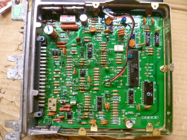
-
Don't forget the "black box" or the "voodoo" part. "Dr. Bosch's Black Box of Analog Voodoo and Wizardry". That's what makes the engine go vroom. * "DBBBOVAW"
-
That's awesome. You totally nailed it!!
-
Is your 260Z a manual, or an automatic transmission? On the manual cars, the EGR relay only controls the EGR system. But on the automatic trans cars, the EGR relay also controls the ignition timing by switching the ignition module to use either the retarded and advanced pickups from the distributor. So, if your car is a manual, then yes... The only implication of removing the relay (and it's associated wiring) is to the EGR system. But if your car is an automatic (or came from the factory originally as an automatic), then there will be implications to the ignition system as well.
-
Haha!! Very nice! I'll PM you! Thanks!!
-
Unless you're really worried about authenticity for your specific build date, I wouldn't worry about it. Basically, it appears there were two versions of that early master cylinder, but the only difference was how they marked the "F" and "R" output ports. Up until around August or September of 1970 the masters had the output port locations stamped with the letter "F" or "R". But then after that, they went to "cast-in" identification marks. I jokingly called them "early early", vs just "early". Haha! The bottom line is that the master cylinder you had rebuilt was used on cars before the fall of 1970, so it's "too early" for your build date. There was some discussion about the changes in the early style master cylinder here in this thread: Page 3 https://www.classiczcars.com/forums/topic/65579-brake-master-cylinder-46010-e4602-up-to-91971/?page=3
-
A little pedantic and I'm not sure how detailed you're trying to be with the restoration, but neither of those master cylinders are the correct one for your car. The correct one is same shape as the one you had rebuilt by White Post, but the "F" and "R" circuit markings should be cast in instead of stamped in. The master you installed is for an earlier car than what you're working on. So out of curiosity, was White Post able to completely rebuild that master? I was trying to rebuild a cylinder like that but was unable to find a source for rebuild guts.
-
Haha!! I do!! I need one!
-
Disconcerting that your AFM numbers went a little leaner when you tightened everything up. The tightening might be related, or it might be a red herring. But disconcerting either way. So did you ever try giving it a little bit of choke enrichment with the lever while you're driving? Does it react as expected and the numbers come down?
-
Oh, and something else changed recently... Couple days ago, this thread was not visible to me unless I signed in. Maybe the whole sub-forum of "website questions" was hidden to guest users? But today it's not hidden. I was able to view this thread without signing in. Obviously not able to POST in it until I signed in, but I WAS able to read it. Not sure that's how you wanted things to work.
-
When I visit the forum, I use the "Topics Last 24 Hours" option. And I poke around without signing in because it's faster, easier, simpler, and I can do it from pretty much any location or device without having to worry about any security concerns. So it's safer. When Zed Head checked, I may have been one of the 135 people viewing the forum without being signed in. This is the page I start with: https://www.classiczcars.com/discover/20/?&view=condensed When I'm not signed in and I click on the "1 hour ago" link, it takes me to the first post in an 18 reply thread. - Undesirable However if I DO sign in and click on the same "1 hour ago" link, it takes me to the post that was made 1 hour ago. - This is what I want But regardless if I'm signed in or not... if I go to the All Activity page here >> https://www.classiczcars.com/discover/ and click on the "1 hour ago" link, it doesn't matter whether I'm signed in or not... It always takes me the end of the thread. (Again, which is more desirable, at least to me (and Zed Head).) So @Mike , the code is clearly in there. Signed in or not.. Just figure out why the "all activity" page operates differently than the "last 24 hour" option. It shouldn't be a cookie thing since it would work the same way for all users. And all of this is clearly a different discussion than "unread since last visit"... THAT most certainly requires cookies, etc. But the links we're talking about should not be a cookie or sign in thing.. And as for menu at the top. I like the way you have it now. It's there if you need it, but off the top of the screen not taking up any unnecessary space if you don't.
-
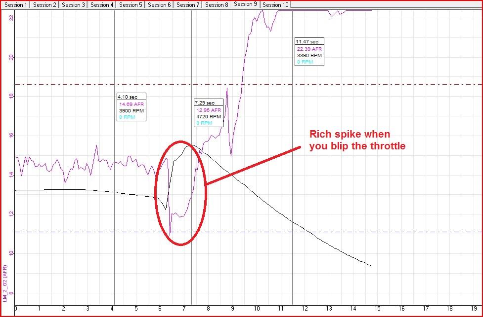
Yeah, even for just another data point, it would be interesting to re-enable the throttle opener system to see what it does to the numbers when you let off the pedal and coast. And as for the rich blip... I'm not sure I understand your thoughts on experimenting with a heavier oil in the dampers than what you already have in there. It appears that the rich blip is already showing the dampers are doing what they are supposed to do. If you want an even deeper rich blip, or a blip that last longer (wider), then you would run heavier oil. But do you really think you need that?
-
Oh, and about that short rich spike when you blip the throttle on a downshift? I see that as your dampers working and doing exactly what they are designed to do... Provide a short term enriching of the mixture when the throttle plates are opened. Just like an accelerator pump would do.
-
Carbs do unusual things (and typically unwanted things) fully closed at high manifold vacuum. The typical thing the SU's do is go very rich though, not very lean. So how about you put a vacuum gauge on it and drive around a little with it connected? Maybe you are looking for a vacuum leak. And... Do you have the throttle opener device installed, connected, and working? It's only job is to prevent the carbs from doing unwanted things at very high manifold vacuums.
-
I don't care for it. I think it was better at the top. But that's just me. I am thankful that the statistics panel at the right is gone. I assume that info is available by some "thread stats" button somewhere. So the aspiring young nerds who really like that kind of stuff can still find it if they want to.
-
Thanks for all you do Mike. My Z and I would be lost without this forum. And I get the fact that this forum is competing for eyeballs with other social media sites like FB. I think you are right about the strengths here. The expertise and knowledge about the classic Z's is top notch. The trick is how to leverage that strength in a way to attract new users without alienating the existing ones. I hope you come up with the magic sauce that pays the bills. I'm on (mostly lurk) a couple of the FB groups, and occasionally ClassicZ will get mentioned as a source for expertise or info. I'm not sure if that get's people to actually JOIN or not, but it certainly can't hurt. I agree. Let's just hope that we can figure out a way for everyone to be satisfied!!
-
I admire that you're spending so much time with Tres Hombres. ❤️
-
I'm in the same category as Siteunseen says - I like to view the last 24 hours Zed Head says - I start from the Topics Last 30 Days page I myself start the same way Site does... View the last 24 hours. So as a data point for you Mike... That's confirmation from three of the top four* contributors to ClassicZ... We don't care about any of that stuff. Just give us a easy to get to list of the recent stuff that has occurred. No fluff, no sidebars on the right side of the screen that shows the "Most Popular Posts", or the "Top posters in this topic". Simple. @Zed Head , do you care that (as of this instant in time) Mike has made two posts in this topic, psdenno has made one, and so have you and siteunseen. About a third of the screen is taken up by all that stuff and I would rather have all that area used by the topic at hand instead. I just don't see the point of knowing who has made how many posts in any certain topic. Does that really matter to the kids these days? It certainly isn't important enough to me to take up that much screen area ON EVERY TOPIC EVERYWHERE. How about a "thread statistics" screen that someone can dive into if they really feel compelled to know stuff like that? So about fancy feeds and views? Don't care. I just want to see what's changed recently. I use last 24 hours like site does, and Zed Head uses 30 days, but it's the same concept. I don't care which sub-forum the change was made in... I want to see reverse chronological order recent regardless of the sub-forum. If it's in a sub-forum I don't care about, I just won't click on it to open it. I can make that decision for myself. Oh, and fix the bug when you click on the "four hours ago" it takes you to the end of the thread where the last addition was made. It works on the "All Activity" screen, but not on the "last 24 hour" view. I've mentioned before that I really like it here, but I also have to agree with @psdenno . Traffic seems to be down, and I know that for me personally, I'm not here as much. Just went back are read all that... Nice rant! Haha!! ☺️ And I'm pretty sure that Patcon does the same, which would make it four out of four.
-
Other than that anomaly in third gear, I think the numbers look excellent. My understanding is that you WANT to run a little rich at WOT, and from watching the engine experts on "Engine Masters", I believe that 12 would be great. In general, the it seems the desired conditions are: A little rich at idle (because engines never want to run at idle, so you reward their good behavior with a little more fuel). A little lean at cruise (because you can, and gasoline is expensive). A little more than a little rich at WOT with 12 being just about ideal (because the extra fuel helps keep cylinder temps down which helps prevent pre-ignition). I'm no expert, but that's what I've gleaned from listening to people who claim to be. Now that anomaly in third gear... That's concerning. I remember asking a bunch about fuel delivery earlier. And just to be annoying, I remember asking about dampers and springs earlier as well. Haha!! 😄
-
Oh, and the reason I posted that video is that it can help give you a good idea of where your pistons are under different conditions. Making it potentially easier to figure out where along the stations you need to make adjustments. Like for example... Just because you are at WOT doesn't (necessarily) mean that you're running at a station way down at the tip of the needle. It depends on the amount of air flowing through the carb, not directly on pedal position. If you have a small camera, you could rig it up to take a similar video of the carb slide on one of your carbs. Might be informative. And about the AFR numbers you're getting... I'm no carb expert, but I've generally found that the SU's run rich at WOT, not lean. Maybe your rebuilt engine flows a whole lot better than stock? Maybe it's something else. It doesn't sound like a vacuum leak to me. That would be more pronounced at idle. A problem with the slides? Like dampers not working right or weak springs? Fuel supply compliance? What happens if you pull back on the choke lever while you're driving? Does everything clear up and look better? Just thinking out loud. ☺️
-
I assume that with enough equipment and calculations, you might be able to predict what would work "right out of the box", but that's way above my pay grade. I would do the same as Patcon and use the AFR numbers as guidance as to which general part of the needle needs to change. Here's a great video of how the pistons in CV carbs operate. This is a motorcycle, but the concept is the same. You can tell by the sound how much he's into the throttle, and you can see what the pistons do in response. I love this video: https://www.youtube.com/watch?v=tR63vrfhwr8 I don't have time to really work on any details right now, and probably won't for a couple days. But, just for starters... Is there any chance that you're running into a fuel compliance issue? By that, I mean, maybe your fuel system is able to provide adequate fuel at idle, but once you start loading the engine, maybe you're sucking the bowls down? And if you let it idle for a minute before shutting it off, the bowls refill before you get the chance to check them? I consider it a long shot, but just maybe? Something like the banjo filters are partially clogged perhaps? Long shot, but I have to ask.
-
Thanks Zed Head. Forgot to mention that I didn't see this thread earlier because, like you, I don't log into the site unless I have something to say. I typically browse without being logged in, and if I see something that I want to talk about, I'll log in. But only then. Why? Because I can browse whenever and from wherever I am. Public networks, open hotel wifi, friends devices if I'm not home. Faster, safer, easier. Pop in real quick just to see what's going on in the ten seconds when the boss isn't looking at my screen. I suspect many of the members do the same thing. Since so much of the classic Z's are linked to classic Owners, I'm pretty sure there is a large proportion that do the same thing. So any behavior that is different between being logged in and not logged in will be lost on me until I happen to log in.
-
And if you get totally convinced it's a needle problem and can't find something stock the fits the bill, let me know. I've cut a few custom needles.
-
Well first two things I would do would be to A) pull the needles to see what number they are, and B) try a thicker weight oil. Paltech probably reused the original N-27 needles, or put in SM needles (because that's what many other people do). Pull em to see what you have? I'm not normally a fan of the SM's but with the number's your seeing, it might be just the thing. The SM's run leaner at idle and richer towards the top. And for the oil, I've gone up as far as 20W-50 in one cer I've messed with. In theory, it won't do anything for steady state, but should help for hard acceleration and throttle blips.
-
So there is that "change layout views" switch below the content option. I don't know what the stuff in there does, but I'm gonna mess around when I have the brain power, but I don't want to go changing a whole bunch of stuff at the same time. If I do that, I won't know what each option does. Is there an option buried in there that says "I have zero need for: dark mode featured content whether a post was made an hour ago, or two hours ago focused content download categories Just show me the most recent posts in reverse chronological order regardless of what sub-forum they are in, and I (with real intelligence, not artificial intelligence) will decide which of those I will open and read"? Oh, and when I do open something, it would be really nice to have a clear unmistakable delineation contrast between different posts in the thread, and a clear unmistakable delineation contrast between quoted content and current content. I don't know if it's just me, but I have never, or ever will, had my significant other bothered by the light because I'm poking around on the forum at night in bed. I'll gladly pass on dark mode if I can use the development cycles for features that I'll use. I really like this place, the people, and the content revolving around our shared passion. I just want it to be clean and simple to use. I'm old and don't like change. 😵💫 I have no idea what that emoji is going to look like for the rest of you guys, but to me it looks like a smiley with some stars next to it.


