Captain Obvious
Free Member
-
Joined
-
Last visited
Everything posted by Captain Obvious
-
 I've done a little digging on the subject (because I'm in a similar situation), and my understanding is that any pan will bolt up to any block just fine. There are some issues however... First issue is fitment into the car. Either the original (middle sump) Z pan OR the rear sump ZX pan will work in the Z. But the converse is not true... The middle sump pan will not work in the ZX. But since you're putting the motor in a Z (and not a ZX), either pan would fit fine. Other issue is that I (believe) you need to use the correct sump pickup tube for the pan. In other words, if you're using a middle sump Z pan, you need the middle sump pickup. (And conversely, if you're using a rear sump ZX pan, you need to use the ZX pickup.
 -
Yeah, if the pressure in that tank vent line gets about 2psi above the crankcase connection, it's supposed to burp the excess pressure off. If it has stuck in the past, I give strong money that it's stuck again. I've never opened one up, but from the pics and the description, it's just a couple springs and sealing balls inside.
-
You already bought the $649 machine, right? You're just looking to see if you can commend yourself on a worthwhile purchase, or need to kick yourself in the butt for buying an the expensive one when you could have bought one for a quarter the price that does the same thing? Well for making that decision, here's some fodder... The only thing fuzzy about that HF welder is the quality, and there's no invertor technology employed there. That HF welder is the big asss heavy lump of copper transformer that we talked about above. Works OK, but doesn't come with any of the adjustability that yours does. In fact, the only thing adjustable about that HF welder is weld pressure and the amount of time the power is applied (because you can let off the handle any time you want to). So it kinda all depends on what you're looking for... That HF welder is old bulletproof technology, but the results will be only as good as the guy using it. Your machine is programmable so you can get dependable consistent results from one weld to another even if you have no idea what you're doing. From what I've seen, in the small amount of poking around I've done for this thread, Telwin has a good reputation, and that spot welder seems to be well a respected portable unit. Not sure the same sentiment exists for the HF offering.
-
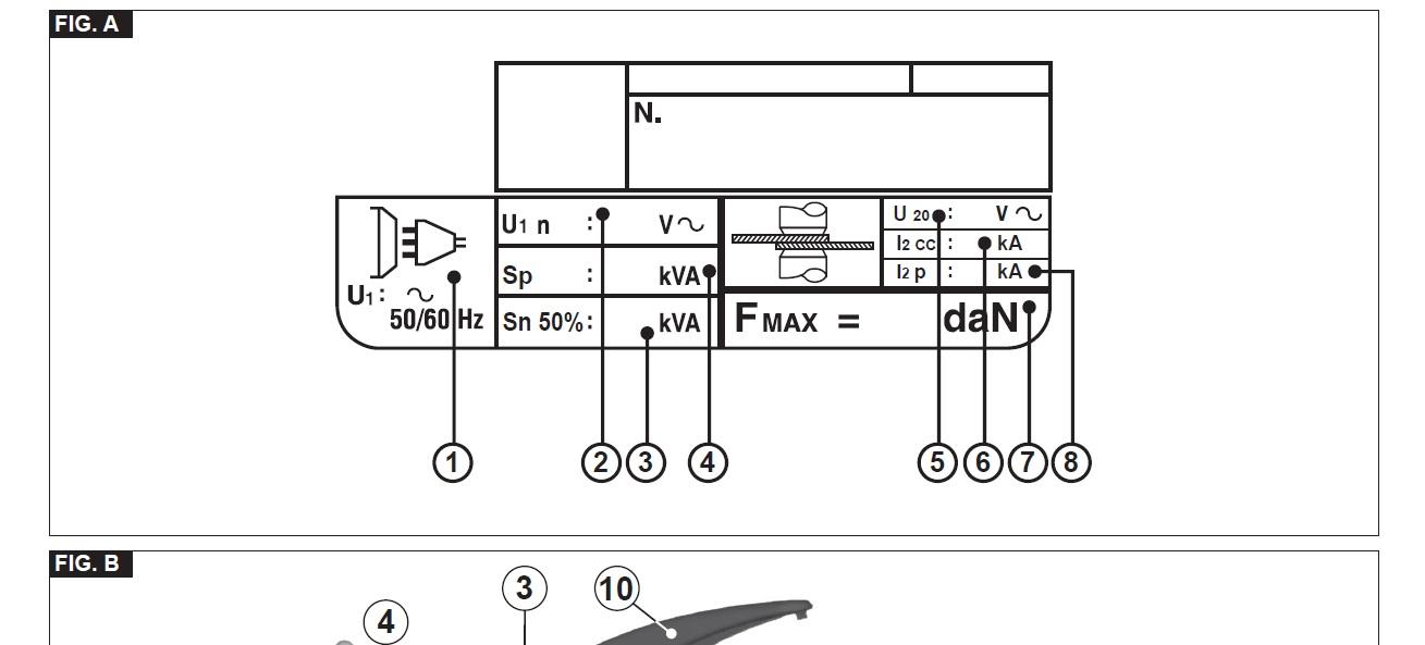
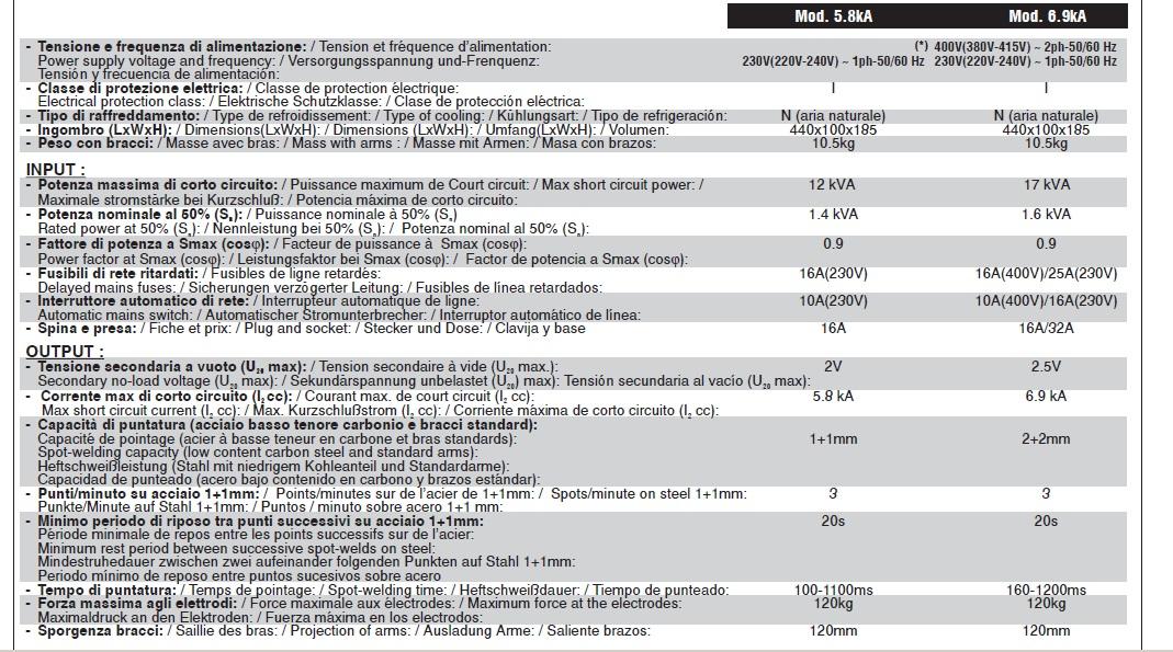
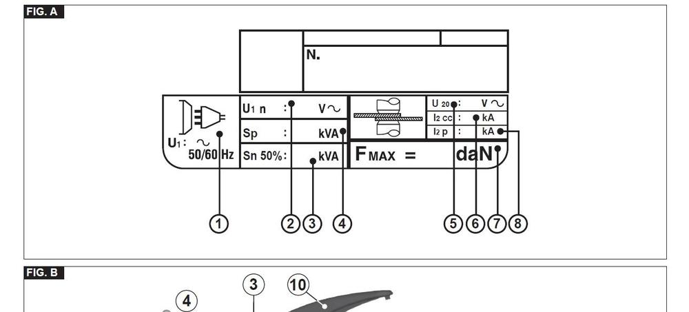
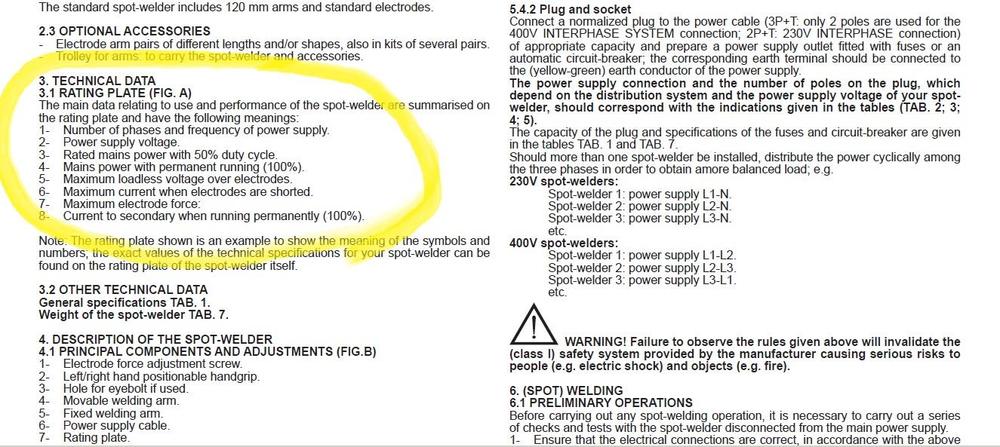
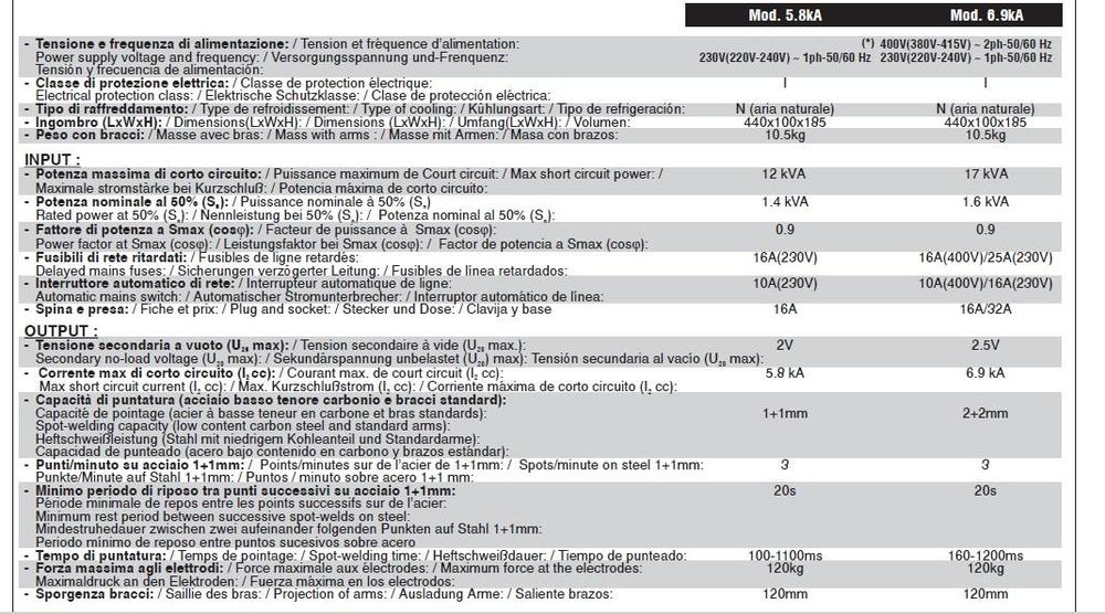
According to the label, that spot welder is made by Telwin. They are Italian (we already knew that). Web page here showing their products (prodotti) >> https://www.telwin.com/en/prodotti That welder is their Modular 230 (or an earlier version of the same), and if you dig down into that model, you can get to a datasheet. Here's some info from the datasheet that may help with the above academic discussion: Enjoy.
-
I don't think it's a typo. I think there's a way to interpret that spec that makes it "correct". The 2.5 Volt welding voltage is probably the open circuit voltage at the electrodes. Problem with converting that to a simple KVA rating, however, is that as soon as the electrodes are closed, you don't have 2.5 Volts anymore. You'll have something less. The 6000 Amp max welding current is probably a very short burst of current that occurs for a tiny instant of time when the electrodes are first connected. The "realistic" welding current is probably something much lower than that. The "rated power" is probably an averaged rating of how much power it draws under "normal circumstances". At 180 spots per hour, you're doing 3 per minute. If it takes ten seconds to position and ten seconds to weld, you've got a 50% duty cycle. My guess is you're drawing an ave of 2.3KW under those conditions. And something else thing to remember... The electronics inside the device consume power too. It's not all presented at the electrode tips. Some of the power consumed from the line cord goes into powering the device itself. It'll get hot inside and that power came from the same cord. So it may draw 500W quiescent power when just idling between welds. No idea.
-
Since you're not planning to use this in a professional every day heavy use application, my recommendation would be to use reviews instead of specs to compare. I suspect the big difference between welders is the duty cycle. And you probably won't be taxing the limits.
-
There is a device called the "flow guide valve" that lives up in your engine compartment who's job is to prevent exactly what is happening to you. I'm assuming that's what you referred to as the "vapor valve"? The flow guide valve has three connections to it. One to the vent line that leads to the gas tank, one to the crankcase, and one to the air cleaner. If the pressure in the tank goes above four inches of mercury (about 2psi), the flow guide valve is supposed to crack open and allow the excess pressure to bleed off into the engine crankcase. I suspect there's something wrong with your flow guide valve (like it's sticky gummed shut). There's a good description of the system in the EC (Emissions Control) section of the FSM. There's also some info on how to test it.
-
The "inverter technology" means that it's more complicated than a AC output with heavy duty variable tap transformer and contactor with a timer. The variable tap transformer stuff is heavy and contains a lot of copper. The inverter stuff is light and contains a lot of electronics. I don't know what "Sn" means, nor do I know how to interpret the goofy numbers on the spec sheets. From what I've heard (from people who supposedly know such things(, welders are one of the prime candidates for "specsmanship". The specs are often convoluted, misleading, and highly dependent on lots of variables and how the unit is used. Fine print and all that.
-
I bet it was the flat top carbs. @Zup
-
Welcome aboard! I suspect if you're a friend of Chris', you're already a special character. This is your place, right?

-
Yeah, I'm not sure now. I took a quick look at some old pics when I took my 83 apart and the TVV is up in the thermostat housing, so my pic with the notes on it is wrong (in at least one area). I'll take a deeper look into my old pics when I get a chance. I do think the long snout sensor is for the EFI though. It fits into the dry thermowell near the back of the head. The beveled nose is supposed to bottom out in the hole for good thermal contact.
-
At least that's the 280-ish version of things. They may have started mounting the TVV up in the thermostat housing for the ZX's. When I get a chance, I'll look through other pics. Unless a ZX guy can come in and answer first.
-
Took the pic out because I think they DID move the TVV into the thermostat housing.
-
Nice work. Those fuses have given their all. I did the same thing on my car a while ago... Tossed out all the old fuses and cleaned up the fuse block fingers before installing the new fuses. A little contact lube on the fuse block fingers. I would also recommend pulling apart and cleaning all the connections between the firewall harnesses and the console. You know... All the connectors that get corroded because the heater core leaked on them ten years ago. Good luck with the project and here's hoping there aren't too many gremlins hiding under the newer paint!
-
Thank you for watching out for me! I appreciate it! Yeah, Austin... I focus on the good parts. And there were enough of those that I can push the other stuff to the background.
-
I've seen your place... I think you may have started just a wee little bit before that new dash arrived. Looks like all of our places!
-
I didn't dig deep, but I believe there are four different covers. 74, 75, 76, and 77-78. At least that's how it appears according to the pics in the FSM's.
-
Agreed Looks great! Now that you have the timing chain on, you can turn the motor over all the way. Did you spin it a couple times just to watch the valves open and close?
-
The dash caps don't work over the Vintage Dash? What's the problem there? I don't have much problem reaching up under the dash to screw in the speedo cable. As crowded as it is under there, it just seems to work. Maybe it's my long spindly orangutan arms.
-
One of the complications about any sort of fuse identification is that there are differences between years. It's not one size fits all for everything from 74-78.
-
Sheesh! Let me try... The ZX is similar construction underneath to the first gen Z. So you know those frame rails on the Z that run from the engine compartment to under the seats? The ones that rust out and get all pushed up and mangled by jack stands? Well the ZX has pretty much the same thing. Who knew it would be so hard to help the Z community.
-
Riiiiiiight. What's a cubit? * Truly sorry for the non-topical response to the thread, but some things are just mandatory.
-
-
I was thinking the same thing... For wasted spark, you don't need any cam position info at all. And for sequential firing, you don't really need a "good" cam sensor. You get the real "timing" info from the crank wheel. The only thing you are doing with the distributor mounted sensor (cam sensor) for is go/no-go to differentiate whether you're on TDC compression or TDC exhaust. (As an academic aside) I even wonder if you have an O2 sensor, maybe you could even tell the difference between compression and exhaust strokes by analyzing the exhaust gas composition. When you first turn the key and crank the car, it's 50/50 right?
-
With the way the original system works, you cannot simply remove or cap off those connections. In addition to feeding the AAR's idle-up function, they also are for the PCV system. The AAR idle-up system CAN be deleted if you feel you don't need the idle-up feature when your engine is cold, but deletion of the PCV system is more problematic There are two hoses involved that complete a "loop" to pass air through the crankcase. One of them connects from the engine block (below the thermostat housing) to the PCV valve. The other one is the hose that connects the top of the valve cover to the intake duct tube. As part of the way the Bosch L-Jet system works is by measuring the air flowing into that system and metering the fuel accordingly. If you start capping off or venting those hoses, it'll play havoc with your fuel mixtures. You need both of those hoses, or neither. And if you run neither, you need to be willing to accept the issues that come with that.