Everything posted by Captain Obvious
-
Any good places or auctions to find 240z or 280z?
Actually I don't like all the links in the OP's post. Links to a whole bunch of auction sites and pics nabbed from copart. Just joined. One and only one post. And hasn't even responded to all the input from other members about his original post. I'd like the OP to participate in the discussion he started and convince us that he isn't a spammer or a bot.
-
Engine test stand
Haha!! I had to look up the Coffman reference, but it reminded me that it's fiddler crab season!
-
Hello from across the pond! Searching for a 240z
Boys, keep off the moors. Stick to the roads.
-
Engine test stand
If the battery is tip-top charged, it should be able to run the EFI and ignition for quite some time even without an alternator.
-
Engine test stand
The what? Did you say computer???
-
Picking up a 1977 280z 6 Hours Away. Tips?
Yeah, but I'm not easy.
-
Picking up a 1977 280z 6 Hours Away. Tips?
What he said. You might not have to replace ANY injectors. Have you verified that the issue is inside the injector itself and not something else?
- 240z - fabbing new front rails
-
Craigslist $5 to sell a car as of today
The scammers will just put the scams into a different category instead. One that's still free. The thing that drives me nuts is the four pages of keywords to force ads to get picked up in searches when they shouldn't. People put "Ignore" and then a whole bunch of keywords. Sure... I can ignore them, but my search engine cannot. Effers.
-
1976 280z engine runs rough then dies, will not idle.
Haha! Well a quick look on the web found the following: Normal Engine Operation At idling speed, an engine at sea level should show a steady vacuum reading between 17" and 21" HG. A quick opening and closing of the throttle should cause vacuum to drop below 5" then rebound to 21" or more. http://www.gregsengine.com/using-a-vacuum-gauge.html So I'm not sure. If a normal engine is supposed to be 18 in-Hg, and calculations indicate you're getting 4 in-Hg instead of 18? A massive intake manifold leak could maybe account for that, but it would be running way lean, not way rich. I'm hoping someone can chime in and show me that I screwed the calculations somehow.
-
1976 280z engine runs rough then dies, will not idle.
OK... So the more important question. Does it make sense?
-
Engine test stand
- Engine test stand
I had the video game. For the original Game Boy.- 1976 280z engine runs rough then dies, will not idle.
Well those numbers look a lot better than the measurements you were getting with the previous gauge. I'm less concerned with the absolute numbers than the fact that it seems to be reacting to manifold vacuum now. Just changing the gauge shouldn't have had any effect on that, but whatever.... Now it just looks like most other old 280Z's that are running either really rich or really lean because of a whole bunch of interrelated issues like dirty connectors, improperly placed connectors, and vacuum leaks. Back calculations from the pressure differential to calculate what the manifold vacuum is in psi... Do the numbers make sense? With the filler cap on and the engine struggling at 400-500 RPM... Decrease of 2 psi converts to 4 inches of mercury. With the cap off and the mixture more conducive to a smoother and higher idle... Decrease of 4 psi converts to about 8 inches of mercury. Did I do that right, and does it make sense?- Engine test stand
LOL! You eeeeeeedddiot!!!- 1976 280z engine runs rough then dies, will not idle.
Anything look wrong? I think so. I don't like the looks of the clear silicone blob on the big gear at the 2:00 position. I suspect that blob was originally at the 11:00 position over by the locking screw (hidden by the big silver metal counterweight). If my suspicion is correct, then it looks like someone rotated that gear way leaner (looks like close to 20 teeth) than factory. An indication that they were fighting a severe rich condition and decided (incorrectly) that adjusting the AFM was the way to fix it. That black silicone that was holding the lid on is another indication that someone has been in there poking around. Of course, none of that explains why your fuel pressure is wrong, but it's something that you'll have to look into as well.- 1976 280z engine runs rough then dies, will not idle.
No. Not unless it's a three way valve and vent the regulator diaphragm to atmosphere when you move the switch to eliminate the vacuum. In other words, it's possible to do this, but not with your typical two port valve. However... You can use a longer piece of tubing with a curly-loop in it ("pig tail") to make it easier to get on and off for testing. I have found that you can bend the two metal nipples so they aren't pointing exactly at each other and fit a longer piece of tube in there temporarily.- 1976 280z engine runs rough then dies, will not idle.
Huh? Someone say cheesesteak??? I've been casually watching the thread, but didn't want to have too many cooks in the kitchen. But since someone promised cheesesteaks... My thoughts are that you guys are getting out in the weeds with the stuff like leaking EGR valves, bent AFM vanes and brake booster issues*. Of course, all that stuff could need some attention too, but I think you need to focus here first: The OP measured his fuel pressure and it was too high. Then he replaced his fuel pressure regulator with a brand new one and it was STILL too high. In fact, the new regulator behaved exactly like the old regulator. That's something that needs to be figured out first and it doesn't sound like it's the regulator. The 40 psi too high with the pump running and the engine off could easily just be gauge error. I'm not too concerned about the difference between 40 and 36 with the engine off, but the second sentence...... "Fuel pressure while idling is 40 psi as well"? The engine will drown at that pressure. So I would pose the question to the collective... Other than a problem with the regulator itself, what could cause the fuel pressure in the rail to be way too high while the engine is running? Return line plugged? Too much static pressure in the tank? *About the weeds... The brakes feel pretty much normal, so there may be some leaking at the booster, but it's not catastrophic. The EGR valve might be stuck open a little and leaking some exhaust past, but that would cause it to run lean, not rich. The AFM vane bent a little wouldn't cause the FPR to be non-responsive. And the water temp switch... The engine is designed to run relatively well with the switch in either position. Just with lower emissions on one position or another depending on the temperature.- 280Z fusible links
- 280Z fusible links
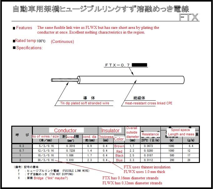
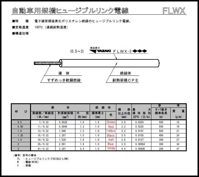
The majority of info on the FLWX sheet was the same as the FTX so I didn't bother to duplicate the translation. Almost everything on the FLWX datasheet was the same as the FTX, so I didn't bother to do both. About the only thing that was different was the color column, so I did that one and didn't bother duplicating the effort on the rest of the info. Guess I should have made that clear and saved you the trouble. As for the amperage rating, the amperage that it can handle depends (among other things) on ambient temperature and the length of the link. My read on the situation is that datasheet isn't for fusible links. It's for wire designed to be turned into fusible links. That said, I agree... I think they could have specified a typical case based on a fixed length at a specific ambient temperature. Would have made a convenient column to include.- 240z - fabbing new front rails
- Starting my Wall Sculpture
Well done!!- Home Built Z 'Full video build'
LOL!!- Parts Wanted: 280 Power Antenna Part
What are the critical features of that part? Is it the kind of thing that could be hogged out of a solid chunk of brass or aluminum? Is there a reason it must be plastic?- Auto 101 test
Annoying for me because it was so littered with ads and crap that I couldn't even get through it! There were ads on top of some of the answer buttons and I couldn't make them go away. Then the whole thing ground to a halt and restarted. I gave up when it did it a second time. I don't know how many questions there were in total, but I was doing 100% before I frustrated enough that I decided I didn't need something like that to evaluate my automotive prowess. I got better things to do. - Engine test stand
Important Information
By using this site, you agree to our Privacy Policy and Guidelines. We have placed cookies on your device to help make this website better. You can adjust your cookie settings, otherwise we'll assume you're okay to continue.


