Captain Obvious
Free Member
-
Joined
-
Last visited
Everything posted by Captain Obvious
-
 Unless the torsion bars are binding somehow/someway, I don't think it could possibly be the issue. They don't do anything to provide alignment. All they do is provide upward force on the hinge. No location control. Just force. Are you sure you have the correct hinges for the car? Did they change anything over the years? How about pulling one of the three hinge mounting bolts out and verifying that the hole is slid all the way to the edge of the slot?
 -
Maybe your fenders are too low?
-
If that block off plate was simply a flat plate, then it won't work. It's more complicated than that. So was it just a flat plate?
-
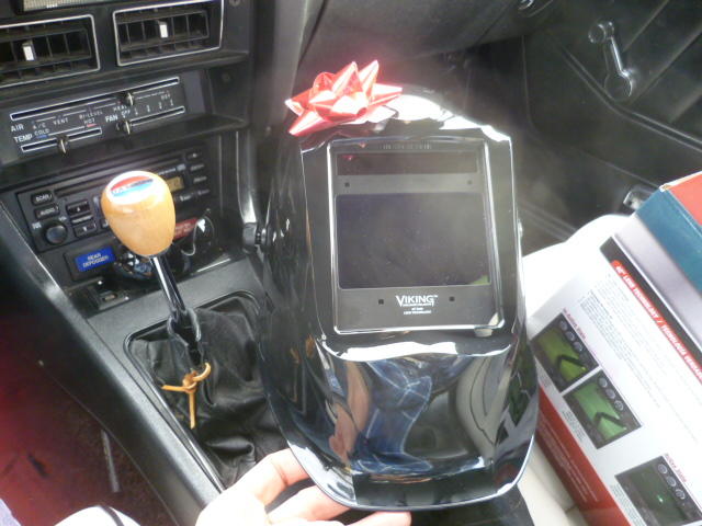
I must've gotten onto the nice list.
-
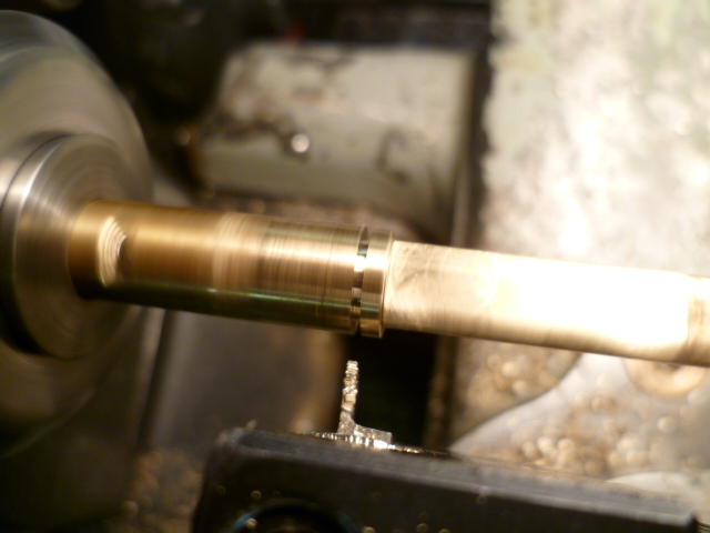
Cool. Must just be a trick of the light. I'm also pleased at how close my camera can focus. And in the cases where it can't focus because it's too close, I've found that I can hold an eye loupe up to the lens and decrease the focal length more. For example, here's a shot of some needles I have here:
-
My pleasure. I can tell you where to find those connections, but I still can't tell you why they're there. Haha! If I had to guess, I would dovetail off something that Chas mentioned... I suspect those connections are some sort of precursor to the valve cover mounted injector cooling fan assy.
-
Perfect. Only thing that catches my eye though is that it looks like there was some needle rubbing on the first needle pic? The shiny spot up near the hilt on this one? Is that just a trick of the light, or is that a rub spot?
-
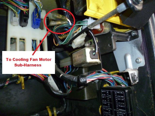
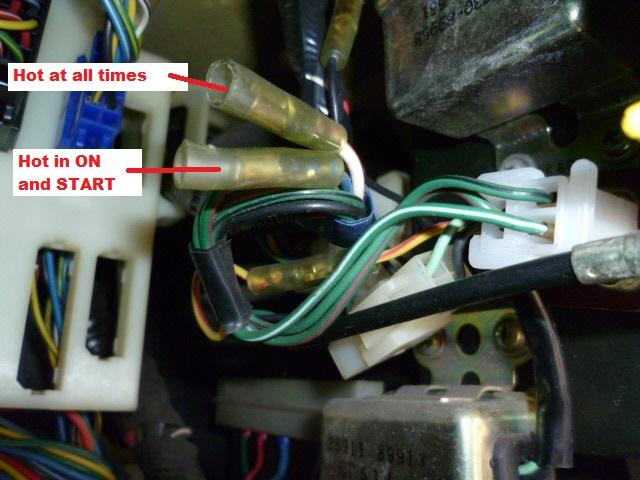
There has been some discussion about that cooling fan motor sub-harness in the past. Unfortunately the pics are dead because photobucket sucks, but here's some threads: https://www.classiczcars.com/forums/topic/46256-always-hot-connection-for-radio-install/?tab=comments#comment-420468 https://www.classiczcars.com/forums/topic/52262-recommendation-for-new-radiator-and-elctrical-fan-for-280z/?page=2&tab=comments#comment-478260 I reattached a couple of my previous pics here... The two connections for that sub-harness are under the dash above the passengers right knee. Tucked up to the right of the glove box:
-
How confident are you that they are the correct needles? I know it can be a little risky (because of potential damage), but unless you are nearly 100% positive they are correct, you might want pull them out of the suction pistons and try to verify the needle number.
-
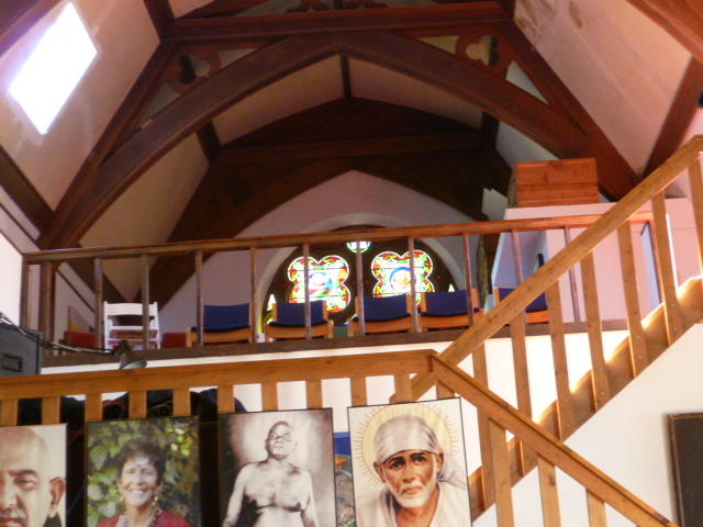
Unfortunately Alice's doesn't exist anymore... Here's what's left: However, the nearby church is still going strong: Here's an inside shot (taken from down among the pews) up towards the bell tower where Alice, Ray, and Fascher the dog slept: So is this a record for just how far off target a thread can be jacked?


-
-
-
And they all moved away from me on the bench there....
-
Touché.
-
Remember that scene at the end of Invasion of the Body Snatchers?
-
Oh OK... I was just kidding. I do have Z parts under the bed. Please don't shun me.
-
Wow! I do NOT , nor have I ever have any Z parts under the bed. So there's an indication that youze guys have the affliction worse than I do!! I feel so good about myself!
-
Haha! Really looking forward to the progress.
-
-
Haha!! The bottom of his car looks better than the top of mine!
-
It's shiny... Too shiny. (wink wink)
-
Hi Kats, I'm with you completely. There are really only one or two cars in my life that I regret not buying when I had the chance. And a Dino 246 is one of them. I had the opportunity to buy one of them a bunch of years ago before the prices reached their current level and I did not buy it. I should have. When you posted those pics of your Z next to the Dino, it reminded me about that. There's another saying in the US.... "Don't cry over spilled milk." It means "don't spend time worrying about things that occurred in the past which you can't change now." In the end, however, I think I would be afraid to drive the Dino because of the value. I think it would just sit in the garage because I didn't want to risk taking it out.
-
There is a saying here in the US... "The grass is always greener on the other side of the fence." In it's simplest term, it's used to describe the guy who looks out his window into his yard and thinks to himself that his neighbors yard always looks nicer than his does and he wishes he had his neighbors yard instead. Put into the context of automotive enthusiasts... People here in the US modify their cars changing over to fender mirrors, changing to right hand drive, re-badging their 240SX cars to Silvia. Converting to clear JDM tail lights on their 300ZX's. The Honda guys peeling off the US hood ornament and installing the red Japanese H instead because it's neat. Wouldn't surprise me to find that kids in Japan do the exact opposite. The grass is always greener.
-
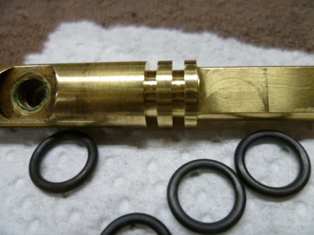
Agreed. (Without the suction piston installed) Put the cover on and put the three screws in but leave them loose enough that the cover can still rotate around the one existing cone nub. See how much play there is. Might be such that with the tolerance of the mounting screws combined with the single nub there might be very little play to worry about. But if you do get energetic... I think all you would need is a steel rod with one end turned to be a precision fit into the hole through the suction piston cover, and the other end turned to be a precision fit into the carb body where the nozzle is installed. Remove the nozzle and then slip the rod into place and then put the chamnber cover on. The precision rod will align all the holes on the same centerline. Put the three screws loosely into place and then use a small syringe to inject epoxy into the alignment nub cavity to cast a new pin in place. I wasn't there at the factory, but I've got a high degree of confidence they did something like that at the factory. You can even see the bubbles in the epoxy material in some of the pins where they didn't get all the air out. That looks like what happened to the intact pin on this body. Looks like a big air inclusion in the epoxy cone: And I wish I could point you in the right direction for that green coating. I've never looked into it. But with as common as it is, I'm sure there's info out there to be dug up.
-
Well to be clear... Your alignment nub has cracked in half and only HALF the nub is stuck in the chamber cover. The other half is usually still stuck in the carb body, but in your case, it has fallen out somewhere along the way and years. Unfortunate, but not insurmountable. Those two cones provide very accurate alignment of the chamber cover with respect to the center bore where the piston slides up and down and where the needle slides into the nozzle. If that cover is out of alignment, the needle will rub the side of the nozzle hole and wear something (needle, nozzle, or both). You can usually get it aligned relatively well just by feel, especially since you still have one good nubbin. But if you were insane and had too much time on your hands, you would make an alignment tool that would be used to fixture everything in proper alignment and use some epoxy to cast a new alignment nub to replace the broken one. A feat I have not yet needed to resort to. And that green coating? I don't know what it is, but it was commonly used. I last saw that on a late nineties Sentra throttle shaft. At least it looked like the same stuff. Last time I was messing around with the throttle shafts, I took a different route and did this: