


Captain Obvious
Free Member
-
Joined
-
Last visited
Everything posted by Captain Obvious
-
 Here's a dimensioned sketch of the OEM bushing. For those of you who don't want to deal with my chicken scratch, the bottom line is: OD ~ 1.977 OAL of bushing outer wall ~ 1.575 after installation (1.985 reference before installation) length of center bolt cylinder ~ 2.565 ID of bolt hole through ~ .677 (clearance hole for 17mm dia bolt shank) Note that the 40mm after install dimension should be on the inside edges of the bent over flanges instead the outside as it's drawn. I'm no draftsman.
 -
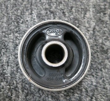
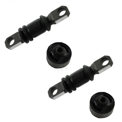
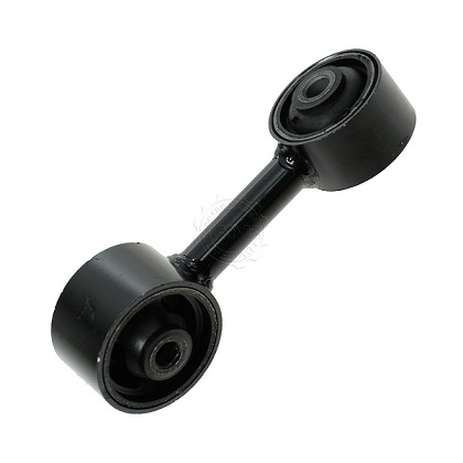
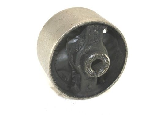
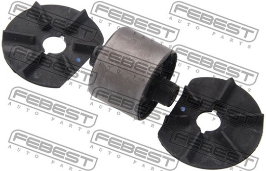
As a back burner project under @Patcon's guidance, I've been looking into this off and on for a while. The most promising bushings I've seen are things like engine torque strut mounts. The upper bar they strap on transverse mounted engines to keep the top of the engine from wretching around as the engine works. if you can't find something that has the exact same size as the original bushing, I muse that you could use something that is a little smaller than the stock bushing, and press it into a thin wall cylinder of appropriate ID and OD. Make the length of the cylinder long enough that there's extra material to swage over the mustache bar. Here's some pics of common cheap bushings that are probably large enough to consider. I bet with a caliper at a junkyard you ought to be able to turn up something .100 or so smaller than the original. There's got to be something out there. Little smaller OD than stock. Same or larger bolt through the middle. Length shouldn't matter so much. Here's some possible candidates. Next time I'm headed to the yard, I'm going to take my caliper: 73-79 Civic Camry: Excel: Paseo:
-
Do you still have your old springs? Maybe just throw them in there to see what happens? Also, if you're interested, I can walk you through how to measure the spring constant so you can compare the two.
-
Forgot something... About the rust (or lack of it), with a press fit of that caliber, it's pretty much gas tight. No oxygen, no rust.
-
Yes, I turned the small sides in. I found I liked the fit better with the short sides inboard towards the strut body. I found that if I reversed the bushings and centered them in the arms, I ended up with too small of a gap where the strut knuckle fit between the two bushings. Of course, since it's just rubber, I could have forced the bushing centers apart a little and forced the strut body between them, but I figured if things lined up naturally without having to do that, it would be better. With the small sides in, when I centered the bushings in the receiving cylinders in the arms, it worked out almost perfect such that the distance between the two bushings was very very close to the width of the strut housing. Seemed to perfect to be coincidental. So I don't know if they were really designed to be that way, but it worked for me. And if you're seeing the same small difference on OEM bushings as I saw on aftermarket MOOG, then I'm starting to believe it really might be intentional. Hark... Did I stumble across something that isn't even in the repair manuals?? If you haven't already pressed your old rear bushings out yet, measure the distance between the two of them, and compare that to the width of the strut body. As for how to fixture the press... I've done so many press operations over the last few years that I don't remember specifically what I used, but it was probably a long bolt passing through one of the bushings to press against the other bushing. Either that, or I managed to fit the control arm down between the parts of the press and straddled the anvil? I don't think I have enough room on my press to fit the arm down inside, so it was probably a long bolt. Something just a little smaller OD than a spindle pin.
-
Hi Kats, Glad to help! I'll draw up a sketch showing what I believe the manufacturing process to be. And one last thought on the stopper... The only thing that should stop that nut from going on any further is the tapered angled surface of the nut should contact a matching angled surface down inside the lug stud hole in the wheel. The four angled surfaces on the four nuts are what locates and centers the wheel properly on the car.
-
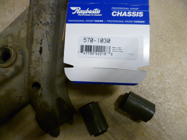
I also found a tiny bit of asymmetry with the rear spindle pin bushings as well. I don't know if it was designed that way, or if it was an accident, but I found a slight difference in the distance the metal collars stuck out of the new rubber bushings. One side was longer than the other, and all of them were consistent (as though it was done on purpose and not an accident). I put all four of them in such that the smaller distance was inward towards the strut body and the longer portion was on the washer and nut side. I found that with the bushing pressed into the center of the control arm recieving cylinder, the distance between the two bushings worked out to almost exactly the width of the strut knuckle casting. I found that if I reversed the bushings and centered them, I ended up with a gap where the strut knuckle fit. Of course, it was a small gap and would have easily clamped down as I tightened the spindle pin nuts, but I figued if I didn't have a gap in the first place, that would be better. Also, putting the longer end on the outside allowed more room for the rubber sealing washer. Don't know if all the aftermarket bushings do that, but I bought Raybestos 570-1030 - There are two bushings per box, so two boxes per car. If you squint right, you can see the asymmetry in this pic. See how the center sticks out farther on one side than the other:
-
Yeah, refresh my memory... Why did you change the springs? I remember having discussions about springs with someone a long while ago, but don't remember the details... Was that you?
-
Yes, I believe the shape of the baffle with the bends has a purpose. It's intended to seal the baffle around the entire perimeter except for the very back corner where it's open. Presumably, the designers thought there would be the least amount of oil spray flinging around back there. Then the bumps and valleys in the middle (in conjunction with the cast ribs on the inside of the valve cover) force that air to swim a crude labyrinth (up and down) in an attempt to separate the liquid from the vapor. Up over the baffle bulge, down under the cast rib. Twice. Before finally getting to the hole at the very highest top part of the valve cover where gravity should also help keep liquid inside while allowing vapor to pass. I wasn't there when they designed it, but that's my read.
-
Hi again Kats, It's kind of hard to describe machining operations with just words and I'm not sure if my description above makes sense. If it doesn't make sense, let me know and I'll whip up a sketch showing the parts.
-
Hi Kats, That's not a stopper, and in use, that surface should not be making contact with anything. Those lug nuts are actually made from two pieces. They machine the threaded portion as one piece, and the tapered section is actually a ring of separate material that is pressed on later. The surface you labeled as stopper is actually the end shoulder of the surface onto which the tapered ring is pressed on. They could have cut the whole thing from just one piece of material, but I suspect they made it out of two pieces because it's easier, and cheaper (since it requires less material with less waste in the form of chips from the turning operations). They probably started with hex rod for the inner part (that way they didn't have to machine the hex), but because of starting from hex rod, they couldn't have any feature larger in diameter than that hex, unless it came from a different piece of material. So they used a larger round rod and cut the tapered section from that, and then joined the two parts together at the end and plated them.
-
I've seen that. One stalk damped a lot more than the other. The check valve on the one that didn't damp wasn't working properly. IIRC, the center shaft was cocked off to the side a little and because of that misalignment, the check valve didn't work right.
-
If you use the proper backup method with the correct sized supporting anvils, you should be able to press those things in and out all day with the hydraulic press without damaging or crushing anything. Having a lathe helps.... My PO did the bushings in my car. He burned the rubber out and put so much heat into the arms that they went blue. Then he hacksawed through the outer bushing wall, and into the control arms a little. In numerous locations. And then he pounded the remains out with a cold chisel and cratered and upset the metal on the inside of the control arm hole. All four were junk by the time he got done with them and I replaced all of my arms and started over.
-
Here's a dimensioned sketch of the OEM bushing. For those of you who don't want to deal with my chicken scratch, the bottom line is: OD ~ 1.977 OAL of bushing outer wall ~ 1.575 after installation (1.985 reference before installation) length of center bolt cylinder ~ 2.565 ID of bolt hole through ~ .677 (clearance hole for 17mm dia bolt shank) Note that the 40mm after install dimension should be on the inside edges of the bent over flanges instead the outside as it's drawn. I'm no draftsman.
-
As long as the dampers stay fully submerged even at full height, then the amount of oil shouldn't matter. If you're able to tune the amount of resistance to lift by adjusting the oil volume, then you don't have enough oil in there. They should be to the full mark, and at the full mark, they should both feel the same.
-
Well I would guess in todays litigious times, maybe he thinks he could be held liable for selling you something that drew more current than the original system was designed for. Especially if your lawyers came calling after your car burned to the ground. With you in it. And a nun. On a bridge that then subsequently collapsed and crushed an orphanage. Or maybe he just doesn't like guys named Granny?
-
I had to read what you wrote about six times before I figured out what you were talking about. Just in case it wasn't just me having troubles... What Zed Head is suggesting is that it would be possible to cut a hole in the stock baffle plate and then connect a tube to that new hole. Then you could also cut a hole in the valve cover anywhere you want, and bring the other end of the new tube out that hole. The end result would be a stock baffle performance, but you could relocate the exit hole anywhere on the valve cover surface. Assuming there's room inside to run said tube without it interfering with the camshaft or valve train.
-
Well here's a theory then... If you hadn't messed with perfectly good needles in the first place and made them richer everywhere with the exception of at idle, then maybe you would be able to drop the nozzles a little and end up with the mixture where you want it... Even at idle. Haha!!! Sorry. Just had to! I agree that 35 mpg would be hard to walk away from. So if you pull the lid off the air cleaner and lift up on the pistons: Are the pistons hard to lift? (Are the dampers damping?) Are the two dampers the same?
-
Really? Cut off? Did you and he discuss the destination application for the bulbs? Did he know you were putting 80/55 bulbs into a vehicle originally designed for something less? That's some strong CYA!!
-
If it's lean only when you first hit the gas pulling away from a stop, methinks you need thicker oil in your dampers, or there is something wrong with your jiggly bits. That or you just need a set of flat tops!!!
-
Will do. Later tonight.
-
That was nanu, not nano.
-
Haha!! You know me well, my friend! As a back burner project under @Patcon's guidance, I've been looking into this off and on for a while. The most promising bushings I've seen are things like engine torque strut mounts. The upper bar they strap on transverse mounted engines to keep the top of the engine from wretching around as the engine works. if you can't find something that has the exact same size as the original bushing, I muse that you could use something that is a little smaller than the stock bushing, and press it into a thin wall cylinder of appropriate ID and OD. Make the length of the cylinder long enough that there's extra material to swage over the mustache bar. Here's some pics of common cheap bushings that are probably large enough to consider. I bet with a caliper at a junkyard you ought to be able to turn up something .100 or so smaller than the original. There's got to be something out there. Little smaller OD than stock. Same or larger bolt through the middle. Length shouldn't matter so much. Here's some possible candidates. Next time I'm headed to the yard, I'm going to take my caliper: 73-79 Civic Camry: Excel: Paseo:
-
To echo what SteveJ said above, there is no significant electrical difference between the 280 headlight design and the prior models. None of the years came from the factory with headlight relays, and to get full effect from any headlight, you really do need to upgrade the system and include some relays. About E-spec, I'm no expert on the topic, but my understanding is that "E-spec" housings are legal in "E", but not here in "A". Also, the FSM lists the stock rating as 50/40, not 60/55. Not sure what the generic sealed beams you get these days actually are, but that's what the manual says.
-
Thanks for checking Zed Head, and thanks for the pic of the 81 cover. Chickenman, I know the stock system works well. A little ashamed to admit it, but the only reason I've even entertained this idea is simply aesthetics. Here's my thinking... I've got a FI car, and currently the PCV valve screws into the underside of the intake manifold. If I were to relocate the PCV to the engine side of the intake manifold (instead of the bottom), then I could connect a short tube from the valve cover to the relocated PCV valve*. That tube wouldn't even have to cross the fuel rail. It could go under/behind the fuel rail instead. Then for the block end connection, I could run a short piece of tube from the block to a nipple on the underside of the rubber intake boot that connects the AFM to the throttle body. The whole thing would be so much cleaner and simpler than the existing system. I wouldn't have those long large PCV tubes running across the top of the engine all the way from the valve cover up to the throttle body. * As a side note, there's even a threaded hole (plugged with an allen headed plug) in the intake manifold down between the runners for cylinders 3 and 4. It connects into the shared internal passageway for the EGR system. It's almost as if Nissan had considered exactly what I'm suggesting. From this old thread http://www.classiczcars.com/topic/22366-efi-progress-on-my-datsun-240k/ here's a couple pics of the integral EGR passageway built into the intake manifold. This one is webbed (which mine is not), but the concept and location of the passageway is the same. He's removing the EGR passageway completely to clean up the look of his intake manifold: In this pic, you can see the flat boss cast passageway between 3 and 4. The boss was never drilled and plugged like the earlier ones were though. But the boss still exists:
