Captain Obvious
Community Member
-
Joined
-
Last visited
Everything posted by Captain Obvious
-
Haha! Geometry!! It sounds like you have plenty of pedal height now!!
-
I agree. Moving the pivot ball towards the slave body should make it engage / disengage closer to the floor. So... A related question... What ID master and slave are you using? I think the masters are all 5/8, but I think slaves are available in 11/16 and 3/4. I think you should be running 11/16, but maybe you could change to 3/4 if you can't get satisfaction using just the adjustment on slave rod length.
-
Couple comments about the above... First comment is that the info you posted above (while all true) does not apply to what grannyknot is experiencing. He is experiencing a clutch engagement at too HIGH of a pedal position, not at too low of a pedal position. Granny is not running out of clutch throw, and in fact he's asking how he could effectively get LESS slave movement, not more. Other comment is I don't agree with the description of the use of the master adjusting rod. The rod is not supposed to adjust the pedal height... It's supposed to ACCOUNT for it. The up-stop bumper is supposed to set the pedal height and then the master rod length should be adjusted such that the holes in the clevis line up with the hole in the pedal. In other words... Set the pedal height first using the bumper, and then adjust the push rod length to account for the hole positions. Rod length should not set pedal height. Does that make sense?
-
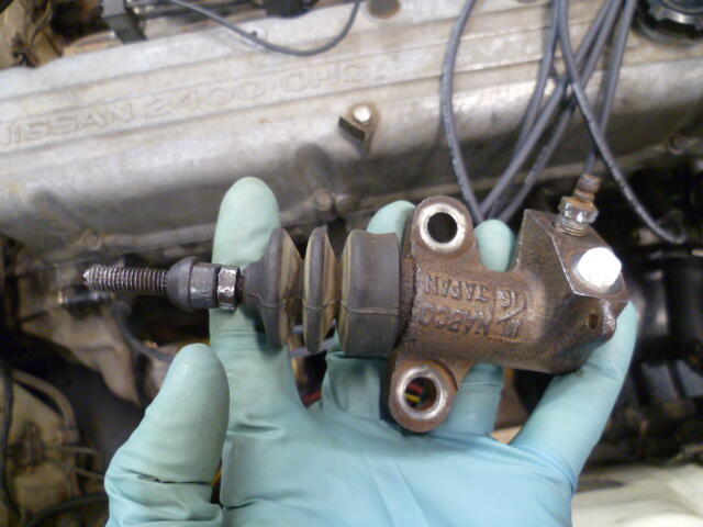
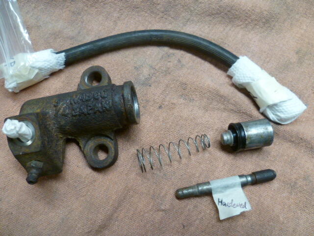
Granny, Are you using an older "non-auto adjusting" slave with the threaded rod, or are you using the newer self adjusting style? Old style: New style:
-
I believe I understand your first three tests and they produced the expected results. Nothing surprising there. I wish you would stop using "continuity" and give an "Ohms" reading instead, but I suspect the results would still be favorable. As for test #4, This part "While my test light was attached to pos battery. I got light when connected to neg side of points." makes sense to me, and is the desired result. But you kinda lost mo after that. I mean, I know what you mean that the points opened and closed (I assume yo (u were cranking the motor over with the starter), but I don't know what you mean by this part "got no power on other side of points". Where did you have the test light connected, and what did the light do? And for your test #5, repeat that test, but try holding the coil wire near (but not touching) the ENGINE instead of the frame. I believe it has been previously identified that you may not have proper grounding connection to the body (frame), but you do have a well grounded engine. The valve cover or intake manifold should be a suitable grounded location to use to repeat the test.
-
Glad to help. And I agree, it's probably a combination of all the parts involved. My 280 has a "down stop" rubber pad on the firewall, and I think that's a good idea. Hopefully you can figure out a relatively easy way to incorporate something like that.. I had one other complication aggravating my situation... I was working on an early 240, and I think my clutch pedal was bent a little. Rotated towards the brake pedal, if that makes any sense. The result of that twist was the foot pad portion of the pedal was closer to the floor than it should have been, and the hole for the clevis pin to the clutch push rod was too far from the floor. Both of those helped make my push rod "too short". I believe that is a known issue on early 240's, but I believe they stiffened the clutch pedal significantly by the time they got to the 280.
-
I just went through this exact same situation. Couple comments... First, there is supposed to be a rubber bumper stop to limit the "up" position of the clutch pedal. It appears to be missing on your assembly. That bumper is important so you aren't relying on the integrity of the little retainer clip that holds the actuator rod into the master cylinder to establish the up-stop. Second, I found the same as you that the down position was not even close to bottoming out the master cylinder, even when the pedal was all the way down. And that's good... You don't want to bottom out the master. Third, I had three masters here, and all three had different length rods. A Luk aftermarket replacement (same as what you have) was the longest. So for me, I adjusted the up-stop such that the clutch was the same height off the floor as the brake. It's less than 8.5 inches, but it matches my brake pedal. And between having the pedal at that height and having the push rod adjusted to it's maximum, mine lined up OK.
-
That's pretty cool.
-
Did you do that hotwire test yet? Once we know the results of the hotwire test and we are confident that everything from the ballast resistor, through the point, to the high tension coil wire is working correctly, we can focus our efforts upstream from there. Break the problem into small manageable pieces.
-
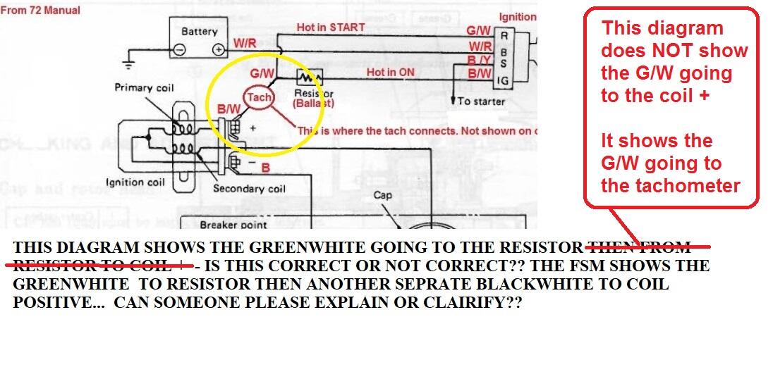
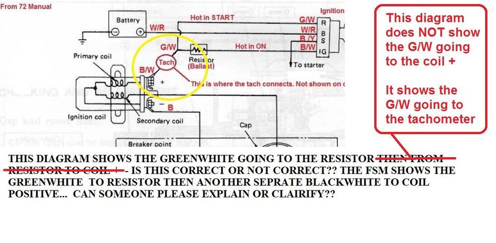
Maybe I can explain the issue you are having with the diagram I posted. What you added to that diagram, is not correct. The diagram does NOT show the G/W wire going to coil +. It shows the G/W going to the tachometer. The OTHER side of the tach is a B/W wire, and that B/W wire goes to coil +.
-
The G/W does not need to be connected at all if you hotwire it as I described. And about your other question... Some of the connections shown in the FSM diagram are made inside the harness. That diagram is a good functional description of how the system works, but it can be a little confusing if you are looking at the wires coming out of the harnesses. For example, the connection between the G/W and the tach is made in the harness and you don't have to tie that together manually. It's already done. When I get a chance, I'll try to whip up a sketch showing the connections in a different form. Still the same electrically, but drawn differently. In the meantime, just simplify stuff! Take all the wires off everything and hotwire the durn thing. Let's try to figure out if your distributor works!!!
-
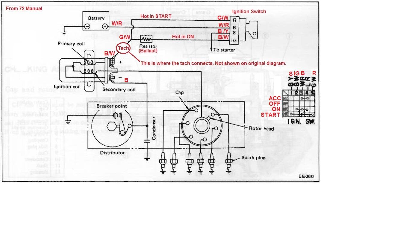
There is nothing wrong in the diagram. It shows the correct wiring. So can you please put the wiring back like it was shown in this pic and hotwire the thing? One wire on one side of the resistor goes to the coil (+). One wire on the other side of the resistor goes to the battery (+). Crank the car. See what happens.
-
If you weren't 3000 miles away, I'd come help!
-
I would try pulling on the choke a little in the situation where you think you are feeling the hesitation. Give it a little more fuel and see what happens? Did you put a timing light on it and verify that both the mechanical and vacuum systems are working correctly?
-
Yup. I'm just trying to simplify the problem and try to figure out where to focus future investigative efforts.
-
Oh, and I'm sure you know this already, but when you're done testing, make sure you disconnect the jumper wire.
-
Good luck with the hunt. I'm not sure I understand what you meant with "pull/ let off at light throttle while cruising" What does that mean?
-
As long as you can adjust the distributor position to get the ignition timing correct (as checked with a timing light), the real clocking of the pump and distributor does not really matter. In other words... If you can get the ignition timing correct, the clocking does not really need to be corrected.
-
I support this message.
-
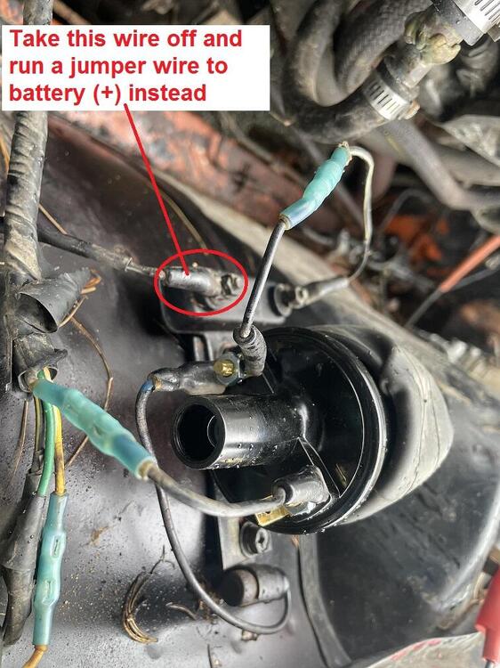
The 240s run the ignition signal THRU the tach, so no... The car (in stock wired configuration) will not spark unless the tach is connected. If you want to hotwire the system and bypass the tach and much of the original wiring, try this... Take the wire off the front side of the ballast resistor. Run a jumper wire from that front end of the ballast directly to that "+" battery terminal. Crank the car and see if you get a spark. If you get a spark, your points are working correctly and the problem is elsewhere. Here's a pic of what I'm talking about:
-
Thanks @zed2. Those seat brackets sure are clean and shiny!!
-
Honestly, with all the hacked up wiring and splices and stuff, I can't tell if yours is even close to correct or not. But my assumption (based on the fact that it won't spark coupled with the cut up wires and splices, etc) is that your ignition wiring is not correct. Can you strip the G/W and B/W mystery wires back a half inch and check voltages to body ground? Negative of meter on body ground and positive on B/W. With key off, on, and start. And then do the same thing for G/W. Off, on, and start. What happens?
-
Both the G/W and B/W are involved in the ignition. Here's the wiring diagram for the ignition system. This was originally created from the 72 manual, but 73 is the same:

-
Gotcha, thanks. So that indicates an issue for me.... Someone in the past has replaced my LH seat with a RH seat. Probably because the original LH seat was worn and it was simpler / easier to find an un-worn RH seat (in the US). So now it sounds like I should find a LH seat.
-
Good deal. I hope karma shines your way for your contribution to the community.