Captain Obvious
Member
-
Joined
-
Last visited
Everything posted by Captain Obvious
-
 I'd love that. Toronto was even close enough that I drove my Z. If I get to Tampa, I'm pretty sure I won't be driving.
 -
I'm not sure which was worse... Austin, Atlanta, or baking in a 130 degree Quonset hut in Memphis!!!?

-
Well I know it's in good hands now. The area that would worry me the most would be issues lurking in the body/paint category. I'm comfortable everywhere else on the car, but not in that area.
-
Why didn't you just switch the struts to the other side? Wow. Pistons? Really? I'm assuming that was not done by the current owner, right? You're not outing him here on the forum are you?
-
Actually looking at the second page of the instructions... That pic is the correct orientation for the NON-Z car applications (like the 510, 610, etc). So it's actually correct for some applications, but not the Z.
-
I think the parts are designed "OK". The real mess-up is this pic: That pic has the parts assembled incorrectly. It has the locations and orientations of the plastic bushing and the aluminum cup backwards. And it also doesn't show the original OEM required rubber bushing on the rear side of the mounting hole in the frame. You see... Never shown in the pics is the original big rubber bushing on the back side of the T/C rod before you install the washer(s) and nut. They mention it in the instructions, but the wording is really confusing. So that said... If you turn the aluminum cup around and put it on first, then that cup is stationary with respect to the T/C rod shaft (meaning that the hole in the middle is just fine to be a tight fit on the rod). And then the oversized tapered hole on the plastic bushing is where the rod wobbles around inside. So yes, the pivot point will be moved out away from the frame hole, but the rest of it looks reasonably designed conceptually. No evaluation of materials used or clearances involved, but at least the concept works. Compression is hard plastic. Tension is soft rubber. Kinda like using poly up front and rubber in the back.
-
Hop, skip, and a jump for you!!
-
Yup. Sorry to be the bearer of bad news. Good luck with the project!
-
I cut out the accordion section for the pic, but I eventually fashioned a different piece to take it's place. It's not pretty, but it works. Here's a pic pulled over from that other thread of another guys solution:
-
Sorry, but no. Everything comes out the front. You have to uncrimp the stainless cover on the side where you insert the key. That silver cover is known as a "facecap", and it's crimped in place. Here's a pic of the facecap removed and the lock partially disassembled:

-
Oh, and by the way.... I like your wheels. Haha!!
-
OK, here's a start: https://www.classiczcars.com/forums/topic/55336-collapsing-shocks-to-push-bumpers-closer-to-body/ There's some pics in there, but the links to my pics are dead because photobucket sucks. Here's a couple pics of my front. This is with the bumper out at stock distance: And here it is pushed all the way in:


-
Glad you got the bumper shocks figured out. I didn't mention it before, but the shocks are a lot easier to move independently without the bumper connecting the two. With the bumper in place, things can get cocked to one direction or the other and bind up. Easier with the bumper removed. I'll be interested in what you do for bumper ends. There are pics around here that show some options and I'll find them if someone else doesn't first. I pushed my front bumper in, but left the rear alone. I think the front makes a big difference. Those pics are probably in the same place.
-
Nice car and lots of stuff to talk about, but I'll start with a quickie... If you drill a hole in the bumper shocks and drain the oil out, they should compress. But if you try to compress them with the (hard) rubber bumper accordion ends in place, you'll be trying to smash them down as well. Won't go easy or pretty. If you're going to push the bumper in, you need to remove the rubber ends first. And then you need to figure out something to cap the ends instead.
-
Nice work. Making parts like that sounds like it would be a simple matter, but they're really not easy. Especially to really make them right. So are you cutting the splines with the part mounted in the lathe? Using the whole carriage in manual mode like a shaper? Little nibble at a time? :)
-
The difference between those is only 20 thousandths. You really think that would be enough to make it not work? Did you buy some of the GM adapters to poke around with? I'm thinking there's got to be a relatively easy way to come up with something. Do you have a pic of the part you made? Neat project. Seems like the kind of non-profitable work I would get hooked into!
-
I had a bunch of parts plated professionally a while ago and noticed that the hardened ones came back very different than the non-hardened parts. And not in a good way. I'm guessing it comes down to the amount of carbon in the base steel. Seems the extra carbon makes them harder to plate? Those distributor spring clips would certainly be a higher carbon content than the typical hardware used on the Z.
-
One time when I was assembling rear bearings, I went through all sorts of gyrations to prevent assembly force from going through any of the bearing balls. I've since decided that it wasn't worth the effort. On subsequent jobs, I've found that the press fit category of the outboard bearing race into the hub bore was a relatively light press fit and didn't require a lot of force. I'm assuming that Datsun designed it that way.
-
Haha! Yeah, sorry for the glare. Those parts are too nice for my car. That's why they're in a box. Haha!
-
Great. Hope the rest of the project goes smooth.
-
Wow that's a lot of work. It looks great, but I can't help wondering if there would have been an easier way to skin that cat. He says from his comfy armchair...
-
Love the mission summary. I've heard it put this way... Misfires leave oxygen in the exhaust stream. AFR pics that up and interprets it as "lean".
-
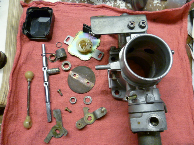
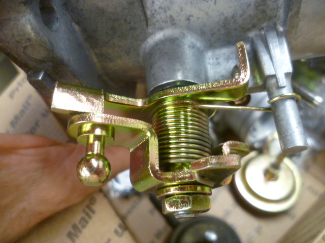
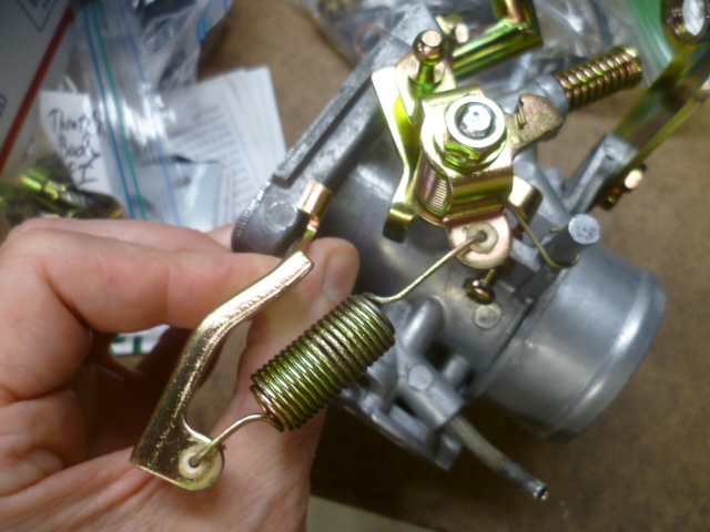
I dug into some boxes here and took some pics. Apologies to @Yarb and everyone else for the incorrect info I posted earlier. Here's the 280Z linkage. View from the top: From the bottom: And here's a close-up where you can see washers on either side of the spring: And here's a shot where I'm holding the mounting bracket with the second return spring: And since I had boxes open, I pulled out a ZX throttle body. Looks like this: So it appears (to the naked eye) that the torsion spring, washers, and center tube are the shared between the Z and the ZX, but the part where the linkage ball and socket joint attaches is different. I believe that part pictured above is from a ZX, not a Z.


-
Yeah. now that you mention it... It appears that the spring anchoring hole does not exist on the lever part you have there. The spring and washers look fine, but that lever looks like it might not be the right part. I'll look at the parts tomorrow with fresh eyes instead of digging through old pics. I hope I didn't give you guys bad advice when I said they were correct.
-
Terrapin, I think those parts look perfect for any of the 280s, including the 78. I believe the linkage attachment piece is from a ZX, not a Z. Details a couple posts below. Exploded 280Z throttle body for reference: