Captain Obvious
Community Member
-
Joined
-
Last visited
Everything posted by Captain Obvious
-
Uh oh. Here we go. Some idiot I know, (in a moment of weakness) bought a rusty pile of early 240 junk that hasn't been on the road since the late 70's. He's been working on it to get it to the point where he can drive it. Those are all true words.
-
So I've never really messed with the window regulator mechanisms, and I've got a 240 with windows that don't go up or down properly, I'm confident that I can just start taking stuff apart until it all just collapses and I can fish the parts out of the door shells, but I'm wondering if there is a more intelligent way to go about it. Can I take the regulators out of the doors and leave the glass in there? Or should I disconnect the glass from the regulators while everything is still in the doors and pull the glass out first? I know many of you guys have been through this before, and I don't need to experiment here. You guys know the best process.
-
I like the description... "Sold one complete Datsun" Are used Datsuns ever really complete?
-
Bummer. But glad you figured that out BEFORE you had a casting made!!
-
Yeah, I was thinking that for shorter and more stable (wider) surfaces, the draft shouldn't be as important. Think about it this way... As the master sample is being pulled out of the sand, those surfaces will slide (scrape) against the sand. But if they are short, and if there isn't a thin delicate section that needs to be preserved, it's not as important. That's why the cooling fins needed draft, but those other shorter stout walls might not. About your channel, you could just add the extra metal on the outside now and take care of the internal features on the mill. In other words, lay down enough metal now in certain areas that will allow you to remove it mechanically later. If you're in a time crunch, that could be a way out. I've not messed with Fusion, but I've spend some time in a couple other CAD packages. and I understand the unfortunate need to completely scrap what you're working on and starting over because the tool can't do what you really want it to. Hope you get what you need. This is really a neat project!
-
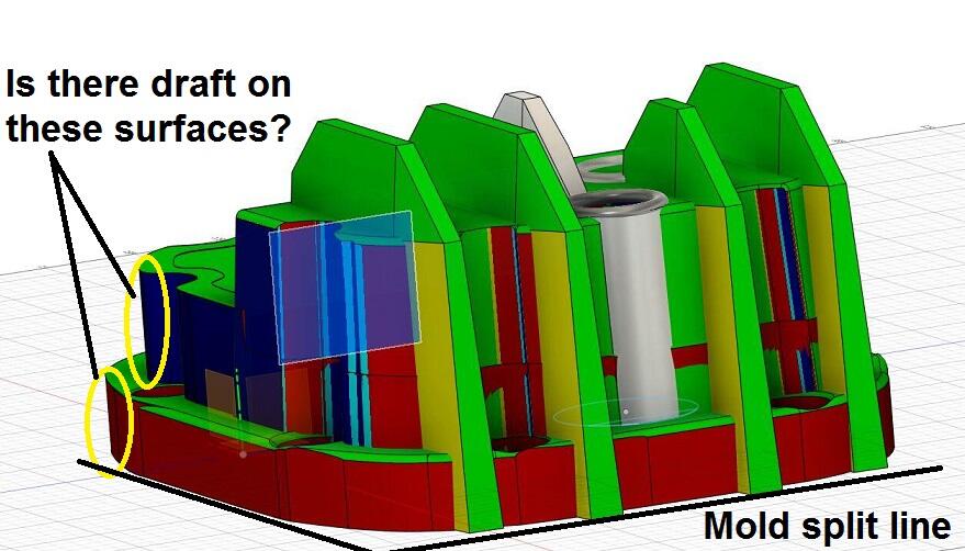
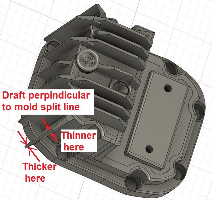
Glad to help. Draft on the fins looks good. Remember... Anything perpendicular to the mold split line should have some draft. Hard to tell from just a pic, but are these other surfaces OK? And they may be shallow enough to not be a problem, but what about the inside edges of your counterbore for your mounting holes around the perimeter? Is there draft on those?
-
Yeah, that draft on the fins is what I was talking about when I said I couldn't tell if there was draft in all the necessary locations. I whipped another quick pic to show ehat I meant. Here's what I was talking about: And I'm still astounded about the cost. That's fantastic for a one-off. Makes me think there are things I could have cast! Haha!
-
I agree. Many people (most everyone?) maligns the 280 bumpers. I think they make a 280 look like a 280. Glad it was a simple fix for the rear bumper mounting. I don't remember if the mounting flanges on the bumper shocks are symmetric or not, but if moving them around took car of the problem, glad it was something simple.
-
Or, if I got energetic. I'd make a mandrel tool to expand the tube larger a couple thousandths and press it in. But I'm not sure if I'm that energetic.
-
I've had the same experience as the rest of you. I've pulled them from engines, and then when I refit them, they slip in instead of pressing in. I assume the metal on the tube deforms on the original press fit. I haven't tried to fix one yet, but off the top of my head, I'd try a Loctite sleeve retainer. I've got experience with Loctite 640 and I'd try that. Might be something better, but since I have that on the shelf, I'd start there and see what happens. Right there on the package, it says "Restores fit to out-of-tolerance assemblies".
-
Haha!! You know... I was gonna suggest that as a possibility! I should have! Would have looked like a rock star! Don't worry about looking like a doofus. I do it all the time! Hahaha!!
-
Well that mounting hole misalignment is much more than the 1/8 inch difference between the two shocks, so it's not the shocks. Maybe the plastic bumper ends shrunk at different rates? Is there a way you can compare the two to see if they are approx the same length? As for the height, IIRC, the mounting holes are all sloppy like with the purpose of being able to wiggle stuff around before tightening? Have you tried pushing one side all the way down and other side all the way up? Also, you can rotate the bumper shock where the mounting bracket is. Maybe that will help? And about that little screw in the middle... It's a gas charged monotube shock. And you just let the gas out.
-
What year are you working on? And is the wiring stock, or do you have aftermarket harness upgrades installed?
-
I'm sure you already know this, but that seal (in theory) should not affect the electrical connection function. In theory. But it's completely conceivable that mixing and matching different vendors parts with various levels of design and manufacturing pedigree... Seems something wasn't done quite right. And if pulling that seal out fixes it, so be it! I'm glad it's that simple!
-
Cool. I'm thinking I'll place the order this coming Wednesday (3/13), so you've got a couple days to look through. Anybody else, same thing. Let me know,
-
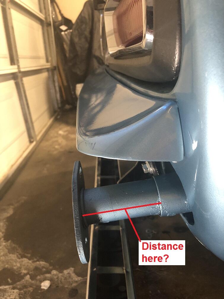
Well that's weird. There should be no way for that thing to change length. There is no adjustment. And I'm surprised that you are able to push it in by hand. The gas shock inside should be stiffer than that. What is the measurement of the amount sticking out of both of your shocks? I'll compare them to my car. From the outer tube to the bumper mounting flange?

-
I'm putting together an order from Eastern Beaver for some electrical terminals bits and pieces. Anyone interested in tagging along and putting stuff in on the order? I'll send you your parts once the order arrives on-shore. Domestic shipping should be cheaper than the shipping from Japan. Their shipping isn't fast, but some of the stuff they have is really hard to find elsewhere. https://easternbeaver.com/Main/Main.html Some examples:
-
I'm not sure I understand the problem... You're saying that the left rear bumper shock is sticking out too far? Significantly farther than the right rear?
-
Rockauto has lots of those. Cheap. I've heard that it can be a problem dealing with them from Canada? If not, problem solved. https://www.rockauto.com/en/moreinfo.php?pk=120105&cc=1209226&pt=5836 https://www.rockauto.com/en/moreinfo.php?pk=477061&cc=1209226&pt=5836&jsn=433
-
Sorry to hear you're selling, and thank you for the shout out. Glad to help.
-
Gotcha. So you probably don't have to do that every time you take the car out. Doesn't really cause a big problem, but as you found out, some of that extra oil will end up running out the bottom of the carbs. Enjoy the drive!!
-
Gordonville, PA. In the triangle between Intercourse, Paradise, and Bird-in-Hand. I'm a little over an hour away. And while I've never designed a casting myself, I've sat with the mechanical designers who did. And I've been in the review seat enough times to make myself dangerous. Like usual. Several products I've been involved with had castings, but never sand. I've been involved with hard tooling die castings and investment (lost wax) a number of times. You really want to pucker... Tell the bean counters that you're ready to cut the check to carve a six figure hard tooling mold. That'll make you review stuff beforehand!
-
Reminds me of Elvira. https://www.youtube.com/watch?v=83WIDuukR0Q
-
I whipped up a quick sketch to help explain what I was talking about above: Also, I'm not too far away from Lancaster, PA. If you do go forward with this, I could possibly be used as boots on the ground locally if necessary.
-
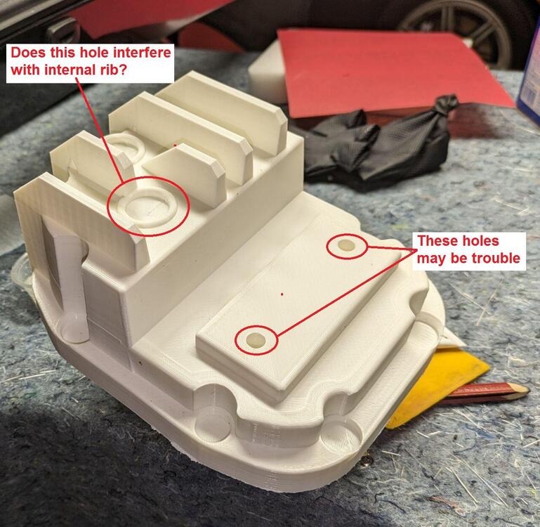
Nice work. Looking quickly at the model, I've got a couple questions, etc. First, the small pilot holes for the mustache bar bolts might be trouble. I think those may be be too small and too fragile of a sand tower and will just snap off when they pull the master out of the sand. I would just make that surface flush, maybe leave a small locating dimple or something, but I'm not sure you're going to have good success casting those pilot holes. And... You're already going to have to drill all the mounting holes around the perimeter, so it's already going to be in the mill. Why not just locate those holes when you do everything else? Why do you need a pilot? Second, I can't tell from the master part if you've got draft on all the necessary surfaces. I'm assuming the foundry will look into that in detail. Last, hard to tell just from pics, but it looks like you might have an interference between the oil hole (fill hole?) and the internal cast rib. Maybe the fill plug hole misses that internal rib, maybe not? Can't quite tell.