


Captain Obvious
Free Member
-
Joined
-
Last visited
Everything posted by Captain Obvious
-
 There are four screws at the upper front of the console. Those screws (two on each side) go into the radio bracket. That bracket does not attach to anything else, so it does not anchor the console to the car in any way, but it does provide support for the two front "wings" so they don't flop around. The other two screws lower than that (one on each side) actually hold the console in place. Those two go through the console and screw into the #10 bracket, which is attached to the transmission tunnel.
 -
When you did it a second time, did you weld both sides of the pin, or just the far side from the cable? Also, did you consider silver brazing the cable into the pin? I think I would have tried that.
-
-
I'm a little disappointed that there wasn't the obligatory "Hey Y'all, watch this!" at the beginning.
-
-
Wooo Hooo!!!
-
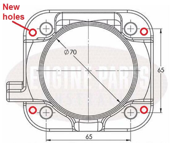
So if the problem with your original throttle body is mechanical stickiness from your cable linkage design, maybe we could work on fixing that instead of completely switching to a different throttle body? But if you already have your mind set on a different TB... It's a long shot, but what is the possibility there is enough meat to add some additional new mounting holes? They can be smaller than the originals (which I believe are M8). If there's enough room to add some M6 holes in the flange without overlapping the original holes? Something like this: Or how about some custom studs that are M8 on one end to thread into the intake manifold, and M6 on the other end to pass through the (larger than they would need to be) holes in the throttle body? Maybe enough meat in the throttle body to use a file to slot the holes enough to get the smaller M6 bolts to clear? It's just a throttle body and it doesn't weigh a lot. Not a lot of load. And it would still seal against the gasket. Yeah, it's a little hacky, but would be easier than welding the holes shut and starting over.
-
Agreed, assuming the valve is mechanically locked with the module unplugged. I don't know if it's a spring loaded vane valve inside or some sort of servo motor driven pintle. As long as the valve position is completely locked with the electronics disconnected, then this would be a good test.
-
Well at this point, the next thing I would do is disable the idle controller system. Pull the low side vacuum hose off and plug both resulting holes. And if that doesn't have any effect, I would disconnect the wire from the coil as well and see if that does anything. I'm not contesting that the system works fine at idle. I'm concerned that it's not working properly ABOVE idle. Breaking out into some sort of oscillation, or switching between it's different modes when it should not be. Something like that. Again, just tossing out ideas in the hope that you get to the root of the problem.
-
Well there's the obvious solutions... Weld the holes shut and drill new, or make an adapter plate? Adapter plate is a little complicated because of the bolt holes all wanting to be in the same locations. Could weld the plate into position or clock the new throttle body 45 degrees to put the mounting holes in a different location. Take a look at this thread starting on about page 6. Lot of throttle body stuff in there, although at the very end (26 pages!!) I still don't know how it ever turned out. https://www.classiczcars.com/forums/topic/64413-just-another-damned-z-car-project-thread/?page=6 @conedodger What did you ever do with your throttle body? How did it all turn out?
-
Well that 2500-3000 oscillation is really wacky. So you said that you had a timing light on it when that was happening and the light did not drop out, right? The actual timing advance number changed some as the RPM's changed, but other than that, no issues? And the hunting issue occurs with both the original stock module and the GM HEI? A test light on the injectors is a good idea. Not sure it'll show anything, but who knows. What about your changes to the BCDD and the blockoff there. Did it run correctly after you put on blockoff revision 2? Wonder if maybe something in there is flapping around. And you have that fancy idle controller thing, right? Are you sure it's not screwing something up? Just tossing out ideas.
-
-
Those pressure readings look OK. Manifold vacuum is a little lower than what I would want, but in the ballpark at least. So what's the assessment of how good or bad the engine runs today? There are 13 pages past in this thread, but what's the latest at this point?
-
Haha! Well THERE'S your problem! So about the video of the hunting issue... You're holding you foot steady and it's doing that rocking back and forth between 2500 and 3K all by itself?
-
Yeah, I agree. It's all wired for it, but they just didn't do it. I guess they just didn't want to add that complexity to the ECU's. Even through the end of the run in 83, they still used the thermotime system instead of having the ECU control the cold start. Certainly a proven brute force system and one less thing for the ECU to have to deal with. Honestly, I've had my cold start valve removed for years and I don't miss it. Sure it takes a couple more cranks on really cold mornings, but for the tradeoffs of being able to completely remove the plumbing leak sources as well as the thermotime switch, I don't really miss it.
-
Do you still have the EGR system installed? It will use a leaner mix during light cruise (on purpose) and inject some exhaust gas back into the mix. I think that at light cruise, they were trying to optimize fuel consumption and reduce emissions. So they lean it out, recirculate some exhaust gas, bump the timing advance, and also purge the carbon can. All at light cruise. In any event, glad you got over your emissions hurdle and good luck with the project.
-
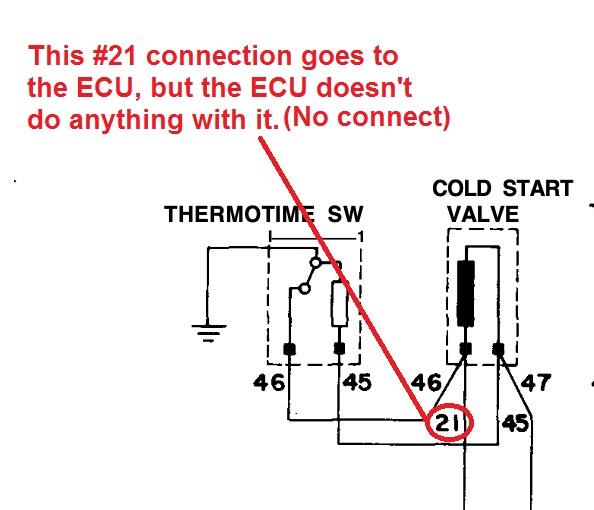
I wasn't there when they designed it, but my read on that #21 connection was to allow the ability for the ECU to fire the cold start injector. They never implemented that feature, but it looks to me like it was wired with that ability in mind. Would be a simple matter for the ECU to drag that side of the cold start to ground if they wanted.
-
Swapping the reluctor wires should not draw anything that would ever pop a 125A breaker. And the wiring between the battery and that part of the car could not support that amperage level without smoking. Something else is going on. Maybe the reversed reluctor was causing the ignition to fire at such an inappropriate wrong time that it was fighting the starter and you were getting locked rotor amperage through your starter? And as for the ballast... I would be surprised to find that the spark is so weak that it is preventing the car from starting. To test that, you could jumper straight across the ballast to get the car to start and then pull the jumper off as soon as it starts? Find out if it will run OK once you get it started? Do it quick so you don't overheat the coil?
-
So I'm glad you got your car through emissions and are off to the next issue, but... You said your car was running really lean. And you leaned it out even more to get it to pass emissions? Are you sure your readings are all lining up? I don't want you to burn a valve or something because you're running scary lean.
-
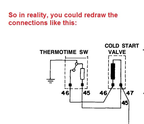
And if you're wondering why those two devices look like they are wired in parallel, it's because they are. But not the way you originally thought. It's confusing because the #21 connection goes to the ECU. but it's essentially a no-connect. The ECU doesn't do anything with it. So with that in mind, you can do this:
-
Increasing the spring tension will make it run leaner. Goes like this... Flap will open less, ECU thinks there is less air going in, and will supply less fuel accordingly. And I don't remember for sure, but I think I would hope for more than 16 in-Hg at idle. Are you sure you don't have a vacuum leak? Cap off everything not required to make the engine idle and give it another try maybe? For example... Brake booster, EGR system, etc.
-
That's a beautiful EM-50.
-
Oh boy. Maybe I'll just stop now. Hey... How bout them Eagles?
-
-
Glad you got it running well. However, just to make my little brain good with the whole ordeal... That same coil ran just fine with the original dual point distributor? Some ideas? Been a long time since it ran at all and anything could have happened between then and now. The coil was borderline before and your moving stuff around and angered the electrons in the coil. Your car runs fine now and it just doesn't matter why changing the coil fixed it.


