Captain Obvious
Free Member
-
Joined
-
Last visited
Everything posted by Captain Obvious
-
 I have a friend who's a big bicycle rider / repair guy and is always putting inner-tubes in bike tires. He says the popular technique in the bike realm is to get a little talcum. He borrows it from Malcolm. He says it's great lube for the inner tube to squirm around inside the tire while getting everything mounted up and inflated. I'm thinking that would work great on the windshield seal as well if you're looking for an alternative to corn starch?
 -
Sorry, but no. I never looked into a purchasable tool to release those Yazaki contacts from the shell. I made one on the lathe. I'm travelling right now, but will take some pics when I get home in a couple days (if you haven't figured out an alternative by then). I also think I have a sketch from when I was designing my tool. That might help identify something on the market that would work. I think/thought @SteveJ may have turned up a tool on the market for that? Maybe?
-
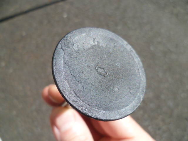
This is the point of polishing it.
-
Ewwwww. That all sounds messy. Hope anyone who was innocently caught up in that comes out OK. And I hope anyone not innocent is held accountable.
-
Gotcha, and makes sense. You can't tell from the pics above, but I took that grinder with the wire wheel mounted outside and I'm doing that cleaning out in the yard and wearing a mask. No way would I want that cloud of dust inside.
-
Oh, and despite the brass color, I think the wheel on my grinder is fine steel bristles. I think they're brass coated, but steel. Use a light touch. The junk came off surprisingly easy for me.
-
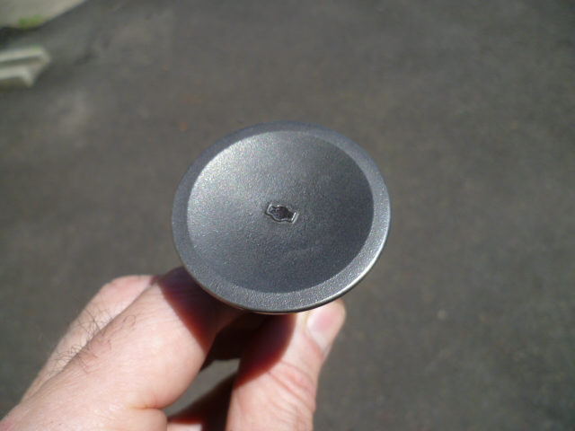
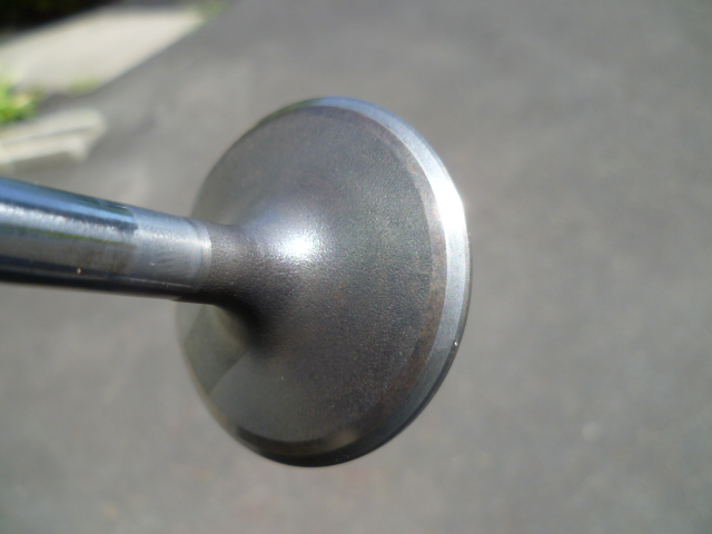
OK, so it wasn't simply a valve lash issue. Not surprising, but too bad. And those valves look a whole lot worse on the stem side than the cylinder side. Definitely enough carbon chunkies to cause the leakdown you saw. Smoking gun there. So as for cleaning up the valves.... Two words. "Wire. Wheel":


-
Haha!! I know it's a longshot, but the insides of the cylinders really don't look that bad. In order to leak that much past the exhaust valves, I would have expected everything to look worse. Longshot, but here's hoping it's something simple like a valve lash issue!
-
Are you sure the exhaust valves in cylinders 1 and 2 were not being held open by too little (less than zero) valve lash? The whole thing doesn't look caked with exhaust carbon that would cause such poor leakdown results. I know... I know... I just have to ask.
-
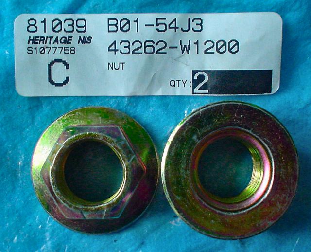
I'm not sure I would trust loctite there, even the red stuff. If that nut comes loose, you could lose a wheel. Highly unlikely, but just not sure I would trust a loctite bond and ONLY a loctite bond. So I've done rear wheel bearings a couple times and I've switched over to the newer style of deformed thread nuts they used on the 280ZX cars. I'm not sure how the thickness of the newer ones compares to the older ones, but if it's thin enough and the deformed threads are down far enough, they could be a simple solution. The newer nut looks like this. Photo credit @ Blue:
-
I've never messed around with converting to the CV axles, so I'm all kinds of confused. With that in mind... You cut length off the end of the stub axle. And now (with just the washer and nut) on the threaded portion of the stub, the end of the axle is below the surface of the nut? How does it look with everything assembled in-situ? The reason I ask is that when installed "as used" the nut will not thread on as far as you have in your pics and you will have even less thread engagement. I'm not really worried that you'll have enough threads, but I am a little concerned that there won't be any place to put your anti-vibration peen. In other words... When you put everything together, it's the bearings and spacer tube (distance piece) that establish where that nut will get tight. Not where the washer bottoms out on the splines like you have in your photo. The nut will become tight before it's as far on as you have it in your pics. Another question is how do the new CV adapter flanges attach to the original rectangular flanges? I've never messed with them, so I have no idea. Do you drill holes for bolts, or do you weld them on or what? And lastly. it should be a relatively simple matter of machining the original wheel mounting flange to accommodate some sort of hub-centric ring. I haven't done it, but seems like you could turn down the original center hub to a smaller diameter and fit a special made centering ring over it. Press it on with no welding required? What is the diameter of the original hub ring, and what diameter are you trying to achieve?
-
They fit just fine. Fuel profile is different (no surprise), but mechanically they mount identically.
-
It's a 3-screw round top. 1972 only.
-
Well if you've been working with new ITB's, they probably have ball bearings and viton vacuum seals on the shafts. They probably are a lot smoother and tighter than the old SU stuff. If you aren't worn through the chrome, then I'd assume you're fine. As for the needles, my notes say that the N-54's were the factory needle for the 72 year. Manual trans I believe. They should be OK for what you're doing. My assumption is over the years, they leaned things out a little bit for emissions. So the 72 needles are a little leaner than the previous years. I've got a pair of brand new aftermarket "N-54s" here that are complete trash. The profile is so far off that it's not suitable for any Z. I think it was a screw-up by the company that sold the rebuild kit (or their supplier). The numbers for yours look much better than what I have here.
-
I meant stick a short piece of wire between the two shorting them together. They are already supposed to be connected hard together inside the wiring harness. One of the working theories is that connection inside the harness has become questionable. If you're not comfortable just trusting some guy on the internet who says "Naaah. It'll be fine. Just short that junk together." I totally get it. Next time the problem comes up, just start by taking the voltage measurements from each of those wires to the alternator case. We'll go from there. Actually, the first thing you should do the next time the problem starts is to wiggle that "T" connector around on the back of the alternator and see if wiggling does anything. Then take the two voltage readings of the two W/R to case.
-
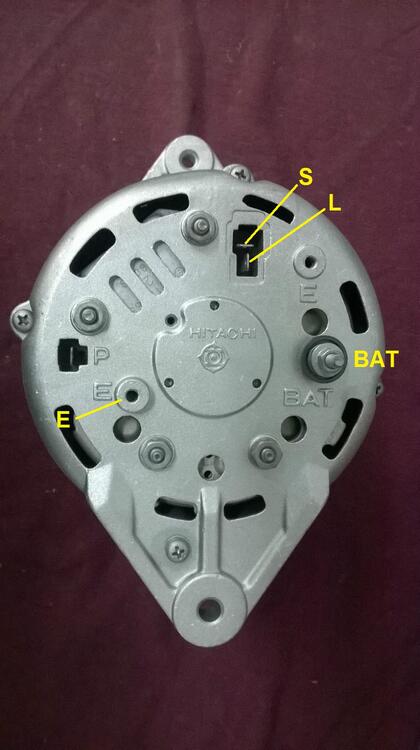
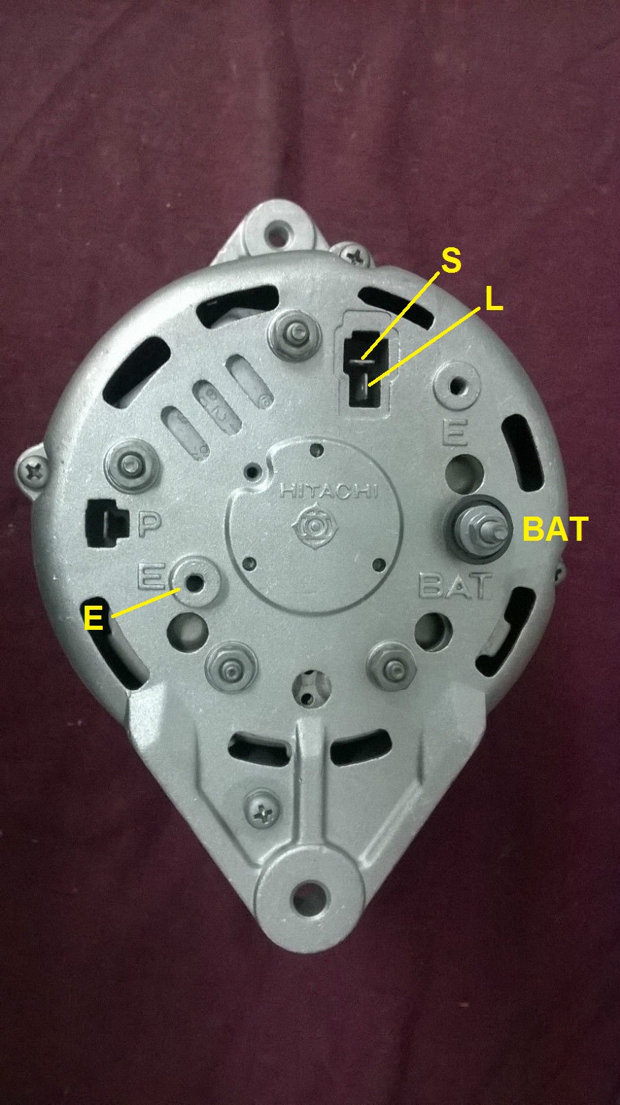
Thanks for the post haircut pic. Much better. So as for the test... Yes, the "T" connector is involved. When the problem is occurring and the alternator voltage is too high, try sticking a wire in the back of the "T" connector at the W/R wire and connect the other end of that wire to the other W/R at the BATT connection. Here's a pic of the back of my alternator. Jumepr the two W/R red wires together like this:

-
I'm pretty much positive the needles that come in the generic rebuild kits are the wrong profile. According to some of the documentation, they claim to be suitable for the 72 carbs, but I think that's incorrect as well. The needles that are supposed to be in the 4-screw SU's are N-27's. I can see the "N" in one of your pics, but can't read the rest of it. Can you read it? Many people change over to "SM" needles, but I'm not a fan. If you want original profile needles and can't find them commercially, let me know. As for sealing up the shafts, yes... One side is pretty simple. Just cap over the whole thing. Other side where the linkage connects is a little more complicated, but putting an O-ring in there would certainly help. How sloppy are they? Is the shaft worn through the chrome plating into the brass?
-
Great work on the heater core stuff. Excellent camera work. I like the AN bulkhead feedhrough.
-
-
Oh, and it looks like your PO was into the harness. Always suspect when that happens. The W/R that goes into the twp position connector... What direction does that wire head? Does it turn the curve and head into the harness? Can't tell on the pic because the tape flap is in the way.
-
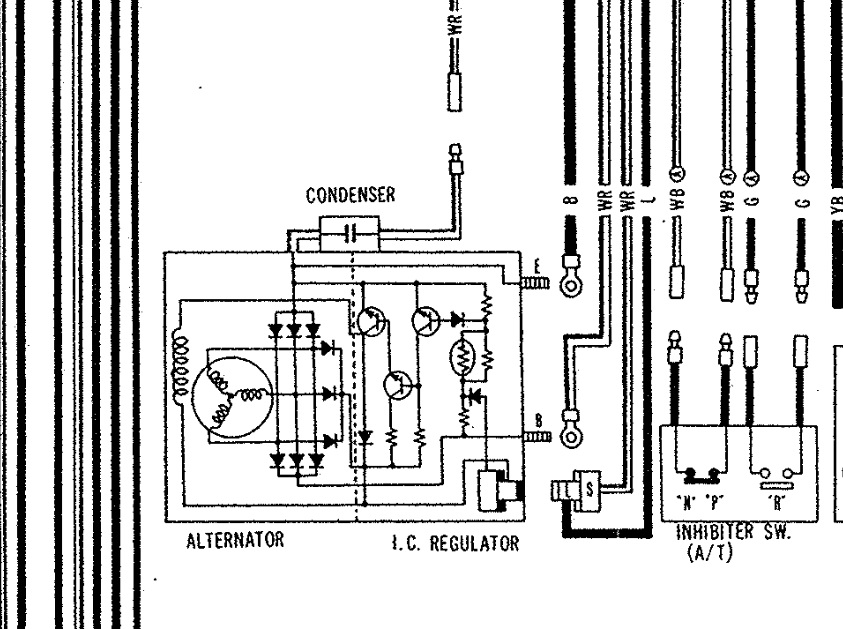
Good. Those colors match the 78 wiring diagram I'm working from. That page EE-15 from the 78 manual is all kinds of messed up. Bottom line is you should have the same voltage on both the W/R wires at all times. So if you're taking voltage readings, it would be good to get one with the car off, and another one when the problem is occurring. One lead to the alternator body, and other lead to the W/R wires. And the idea that Zedhead suggested would be a good test... When the problem is occurring, if you jumper between the two W/R wires, does the problem go away? You don't have to run a fresh wire all the way from the battery to run the test, just run a wire between the two W/R right on the back of the alternator and see what happens.
-
I agree. There are no mis-statements anywhere, but kinda deception through omission. There were a couple feedbacks that highlighted that situation. Some people were surprised and disappointed that the parts they got were 3-D printed. The seller is very responsive to problems and does his best to make it right, but I think some of those misunderstandings could have been prevented at the get-go if it was more clear what the parts are.
-
Yeah, I'm no ebay jockey and was wondering about that. So it sounds like ebay asks you if the part is new or not and as soon as you say your part is "new", they fill all that in for you. I did browse through some of the feedback and it's clear that the guy is credible and trying to make things work. I just think it should be called out specifically somewhere that the parts are 3D printed repros.
-
I doubt the needles in the replacement kit were the correct profile.
-
Uh-Oh. Now I'm worried that we're getting caught up with potential mistakes in the documentation and discrepancies in wire colors. When I was saying there are two W/R going to the back of the alternator, I was operating from this: And that's clearly different than the pic from the 78 manual posted above. So @chaseincats, what color wires do you have going to the two position spade connector on the back of your alternator? Here's a pic showing the connection layout: