grannyknot
Free Member
-
Joined
-
Last visited
Everything posted by grannyknot
-
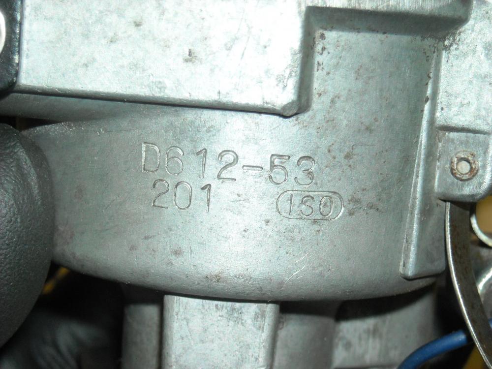
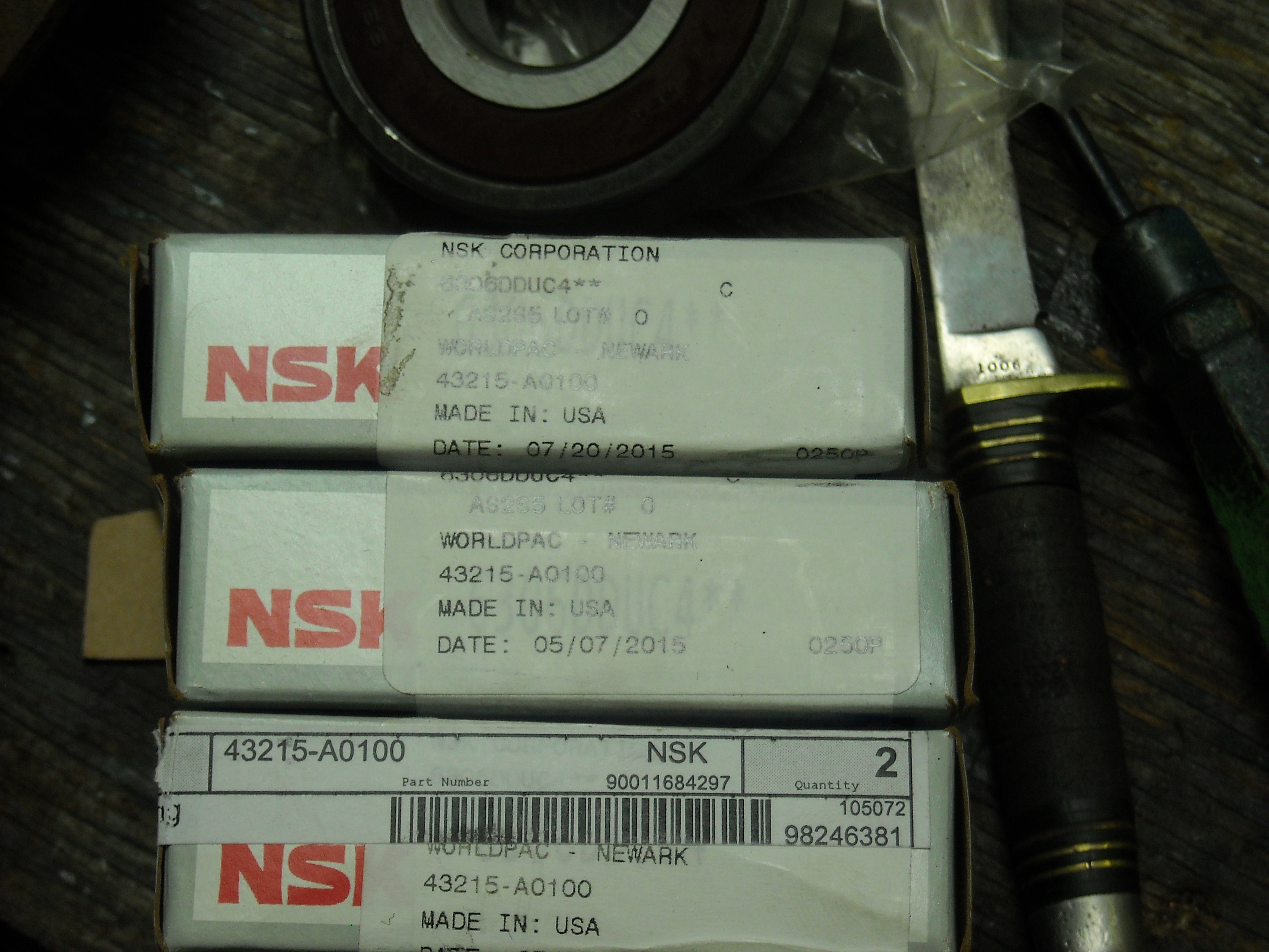
 ^ That's probably a very rare piece you have there, I didn't know it existed.
 -
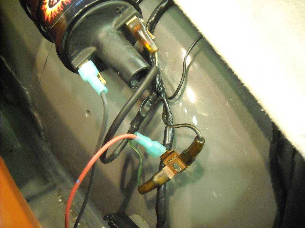
Got the tach working thanks to the late, great EScanlon, this is Enrique describing the early ignition in regards to the coil and tach pick up, Posted 3 Feb 2006 · Report post The "no effect" B/W is the one that goes to the coil in all cases, the one that killed the engine IS the one to connect to the G/W now that the resistor is gone. That's the initial power source for the resistor and then the tach. As you have it now, the tach should be exhibiting "spikes" while starting the car. Trust me on this, if you want a better understanding then continue reading. When the engine is RUNNING (+) power from the battery goes through the fuse box and then to the ignition switch (via a W/R wire). From there it gets sent to the Resistor (via B/W wire #1) which then returns it to the Tach (G/W wire), the Tach then sends it to the Coil (B/W wire #2) and the system is energized and you can have spark at the plugs. When the engine is being STARTED (i.e. the starter is engaged and running) the (+) power from the battery also goes through the fuse box, to the ignition switch (W/R). Here there is a "detour", the (+) is now sent DIRECTLY to the tach (G/W wire that receives the return power from the resistor), and from there to the coil (B/W wire #2 above). As you can see the fuse is totally bypassed. When the engine is running the G/W wire FROM the ignition switch, used in the starter sequence is inop. The power gets returned to the G/W wire from the resistor and then to the tach. When you are starting the engine, the B/W wire that killed the engine when you removed it, is inop as the power is being sent DIRECTLY to the tach via the G/W wire and then the B/W wire that had no effect. The power to the coil goes through one of two circuits BOTH of which go through the tach. Hope this makes some sense. Trying to explain electrical circuits is tricky and can be very confusing. E I doubt you will find a better description then that. So basically I switched the two B/W wire around and everything is golden, so simple but it just never occurred to me. Thanks Enrique. Chris
-
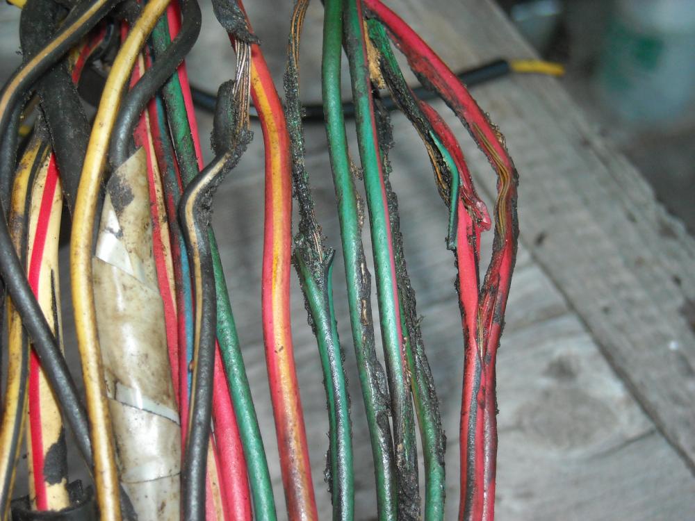
Sounds like it's time to pull engine bay harness and cut it open. This is what I found in a 240Z harness last year and everything was working!
-
-
It looks beautiful but you might want to install a heat shield under the carbs.
-
-
I figured out the fast idle screw issue, I just had the throttle adjusting screws turned too far out so had to compensate with the fast idle screw to keep it running. Turned them in 1 full turn, backed off the fast idle screw, re balanced. ZTherapy had the jet knobs (the two big ones under the carbs) at about 2 1/4 turns down but I found 2 3/4 turns worked best when doing the test where you quickly raise the carb piston. So that all seems to be running well now. Just have to figure out why the tach isn't working now. Thanks, Chris
-
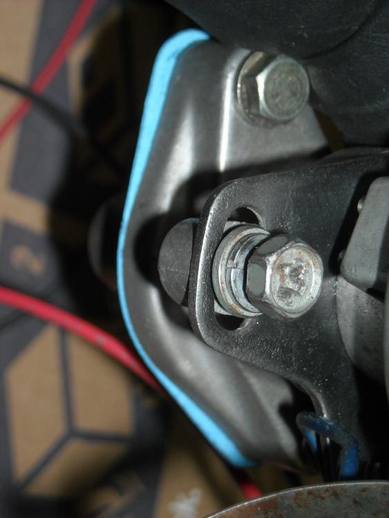
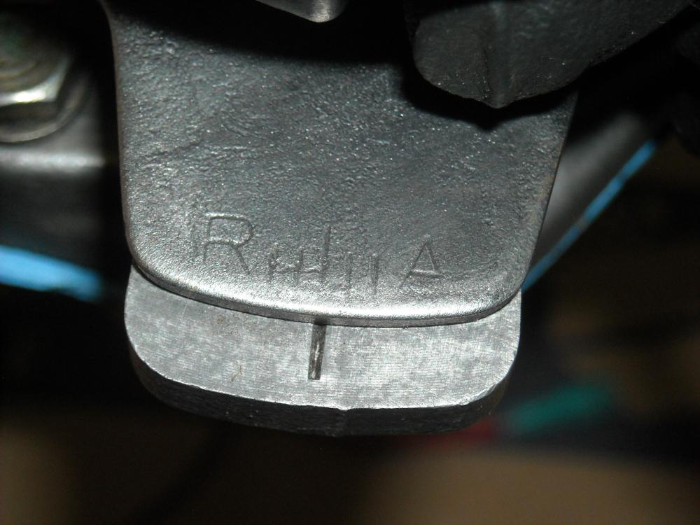
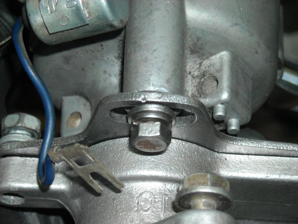
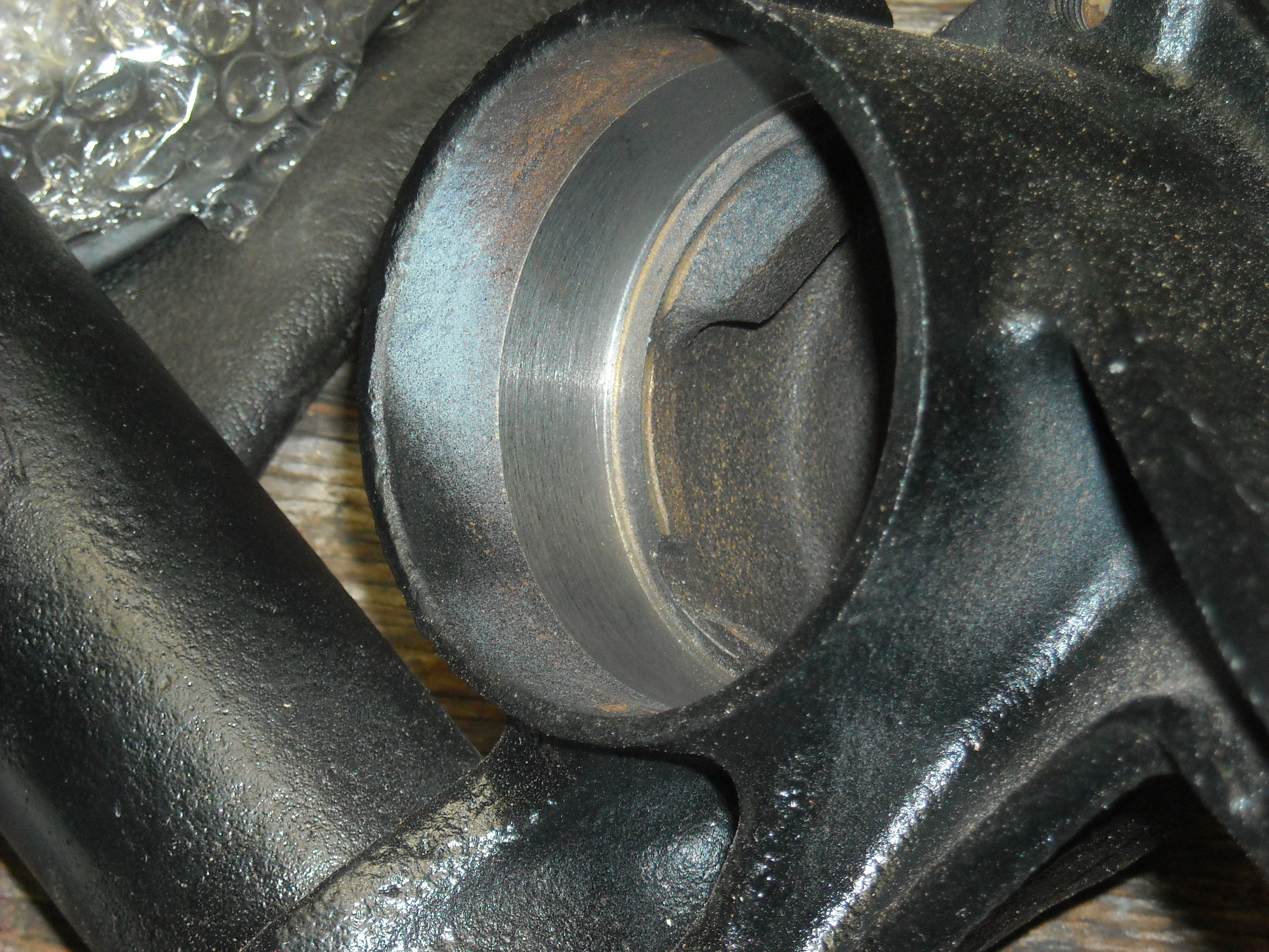
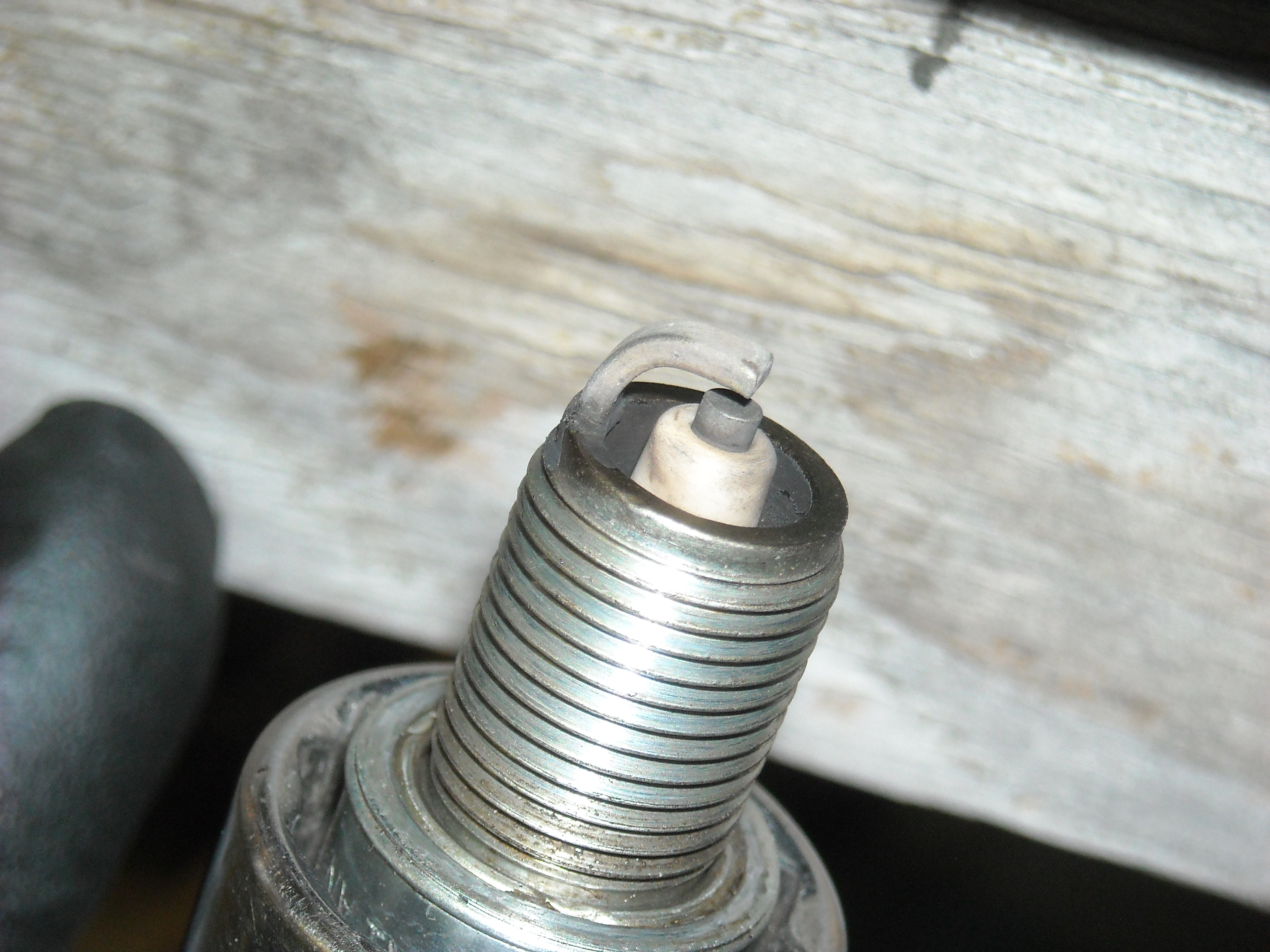
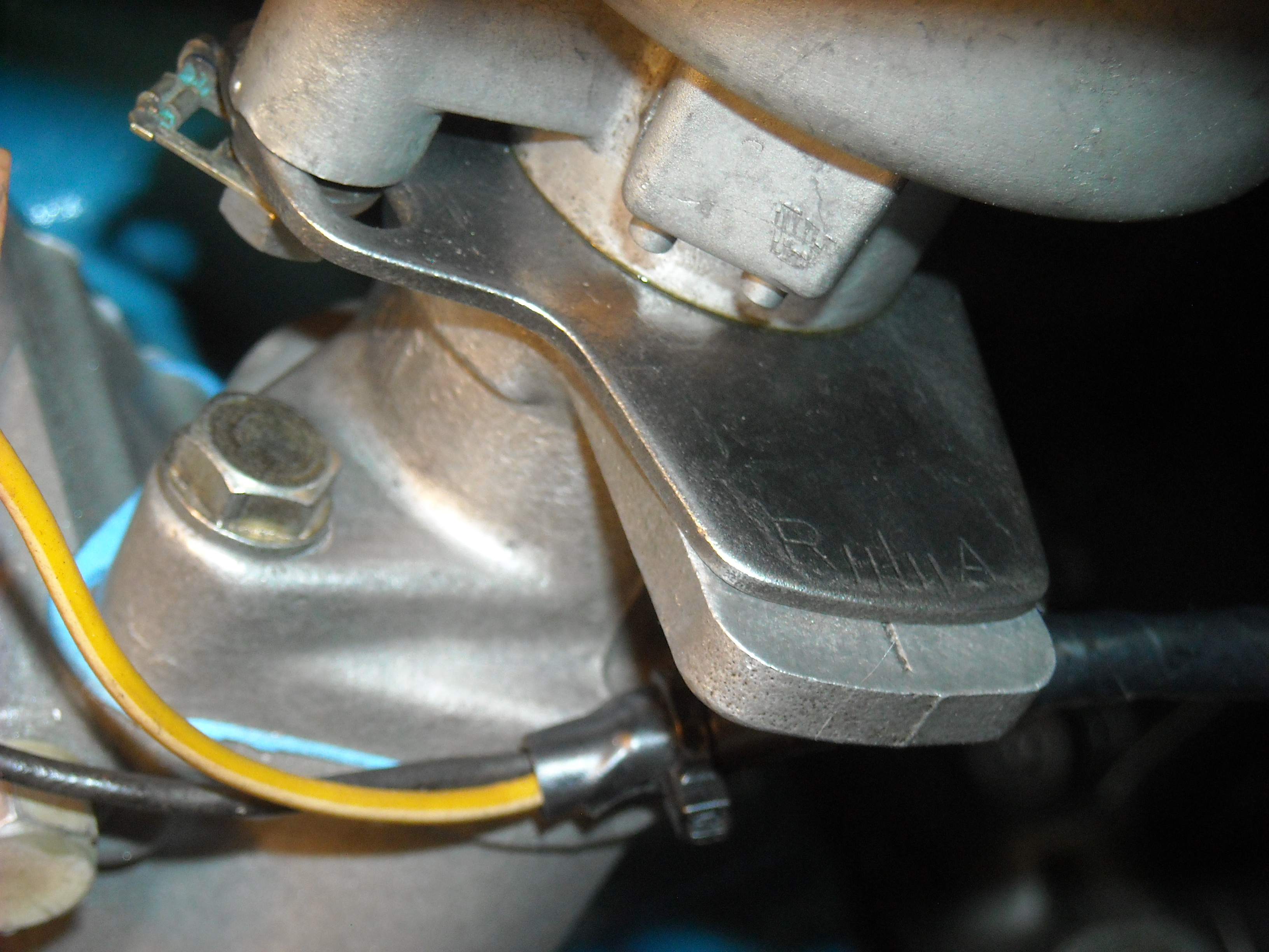
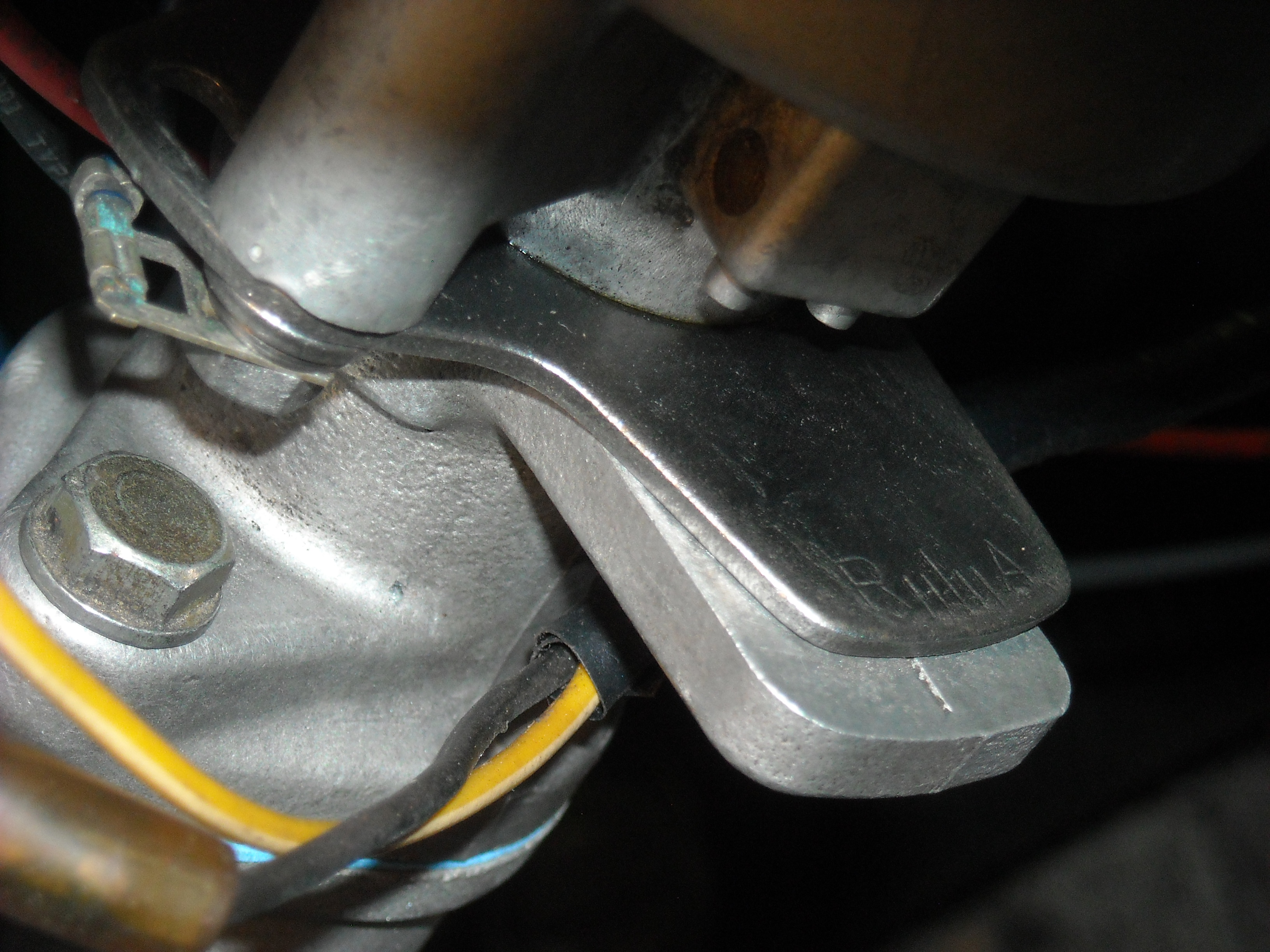
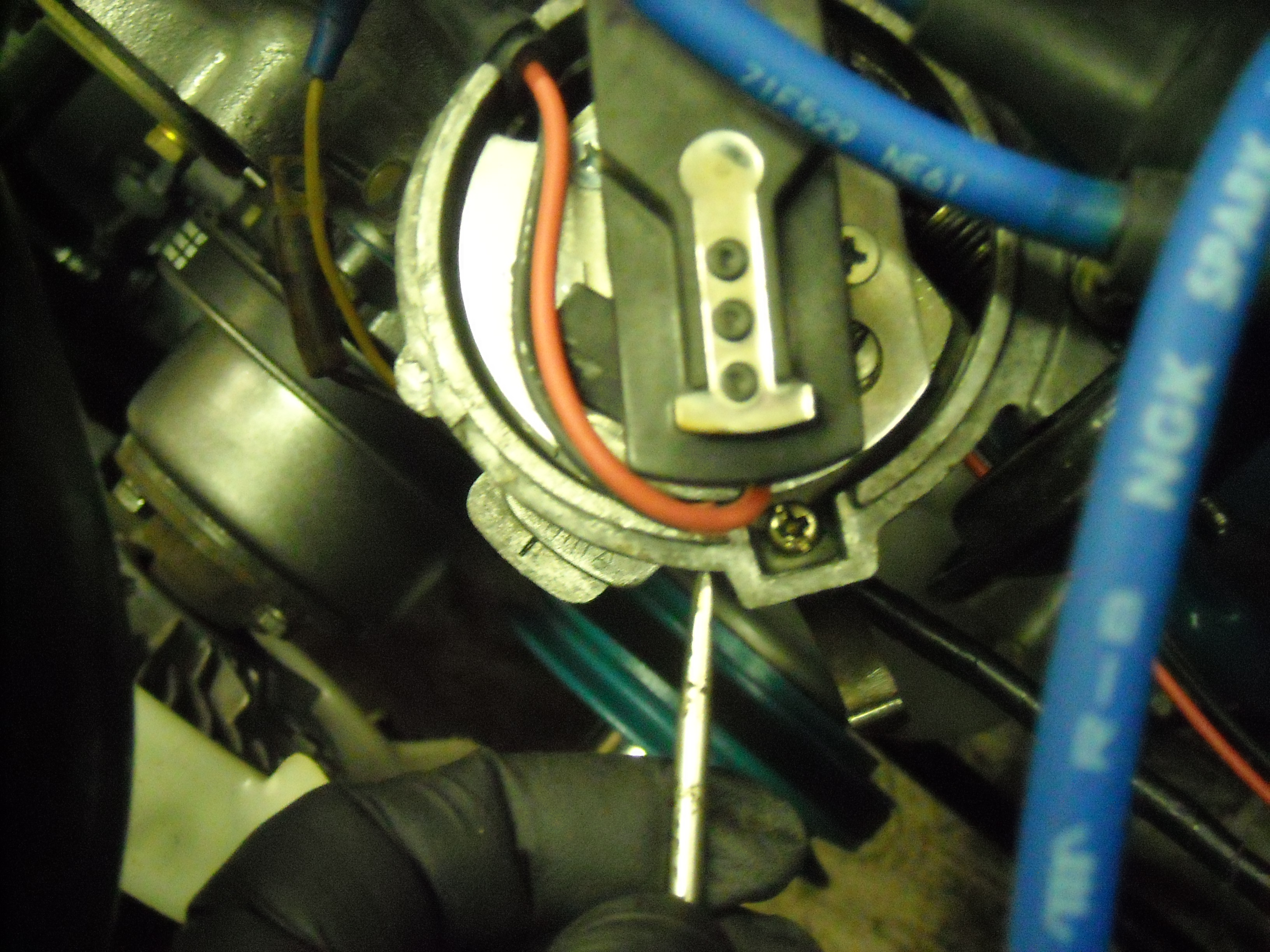
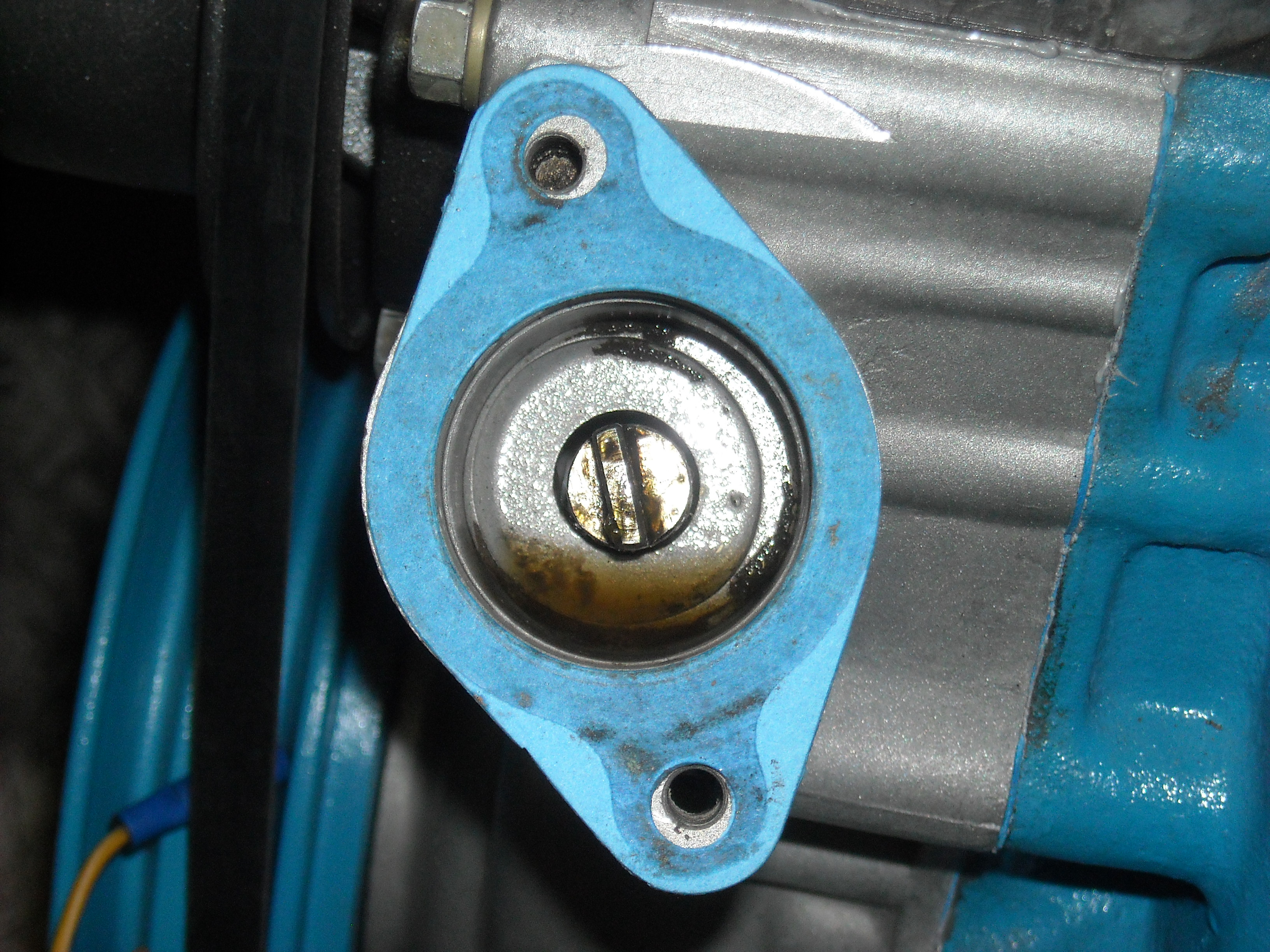
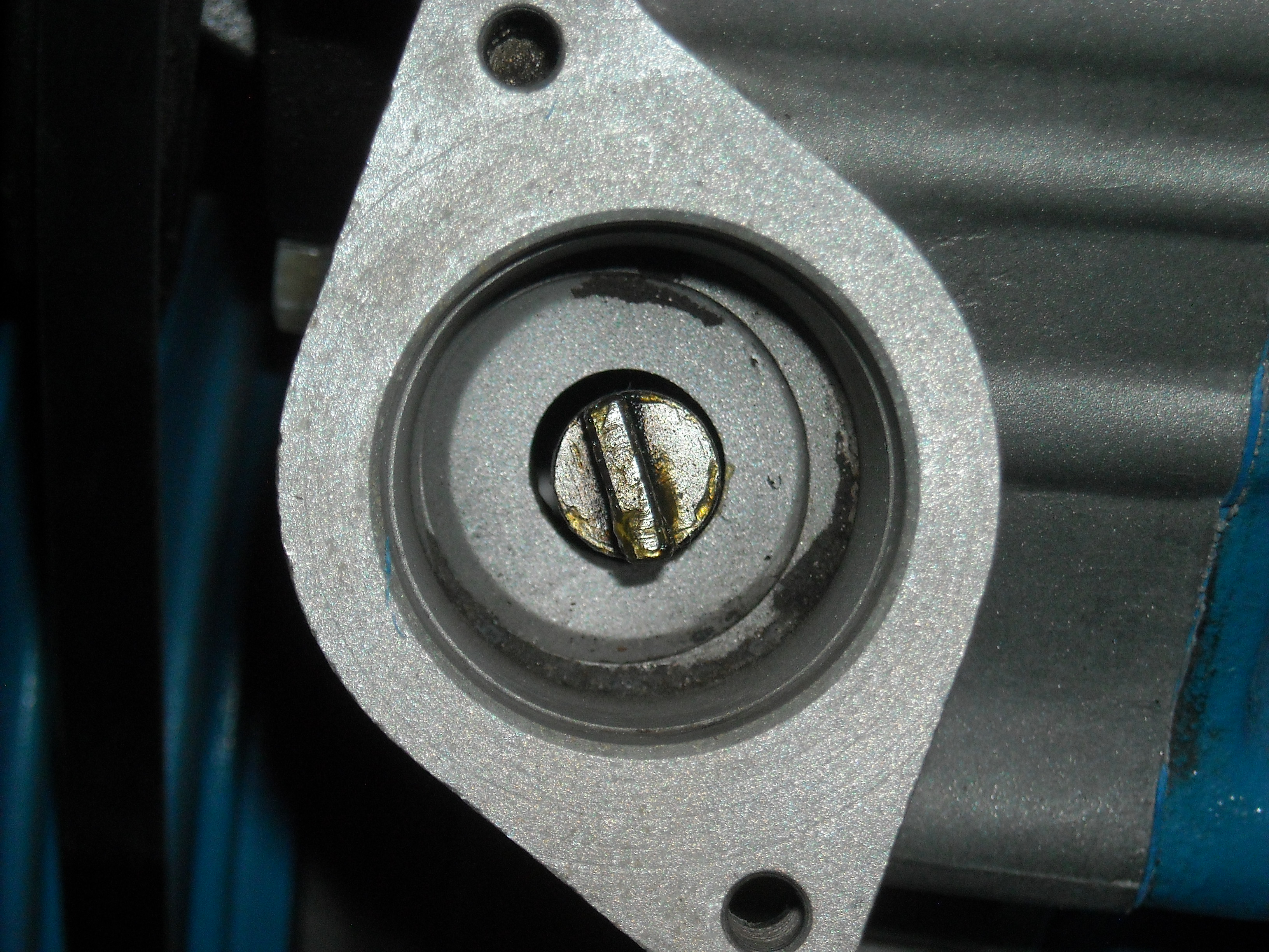
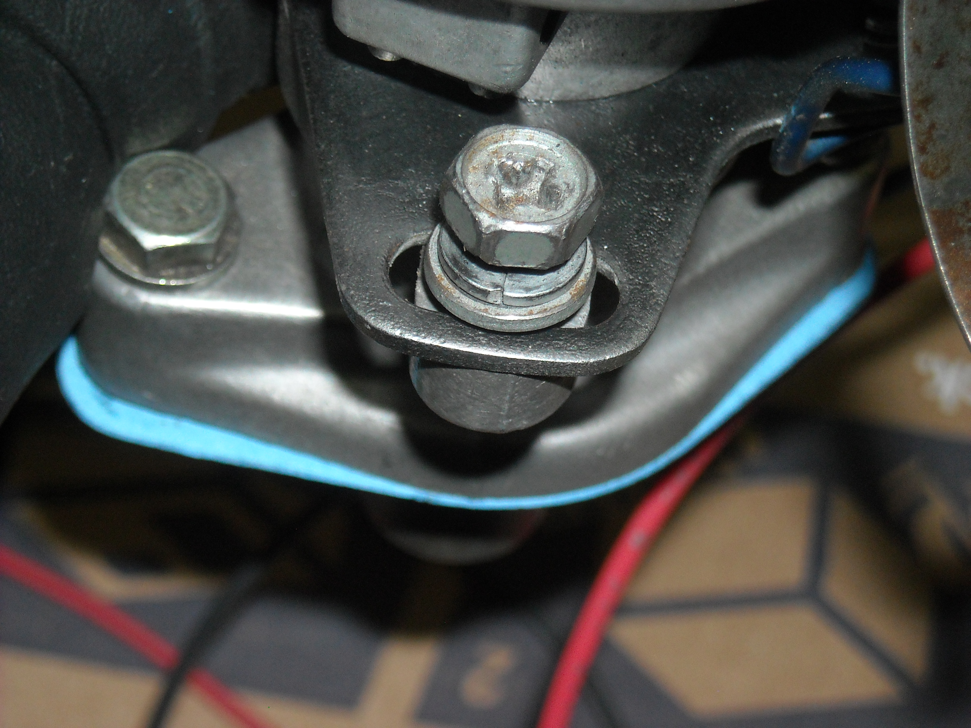
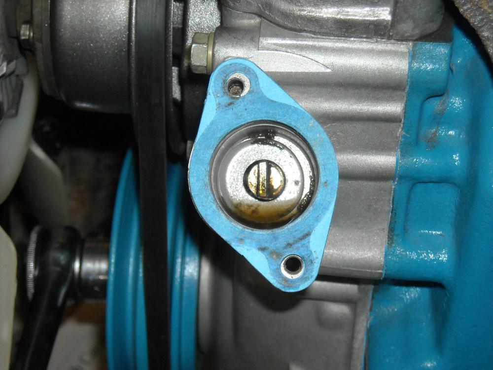
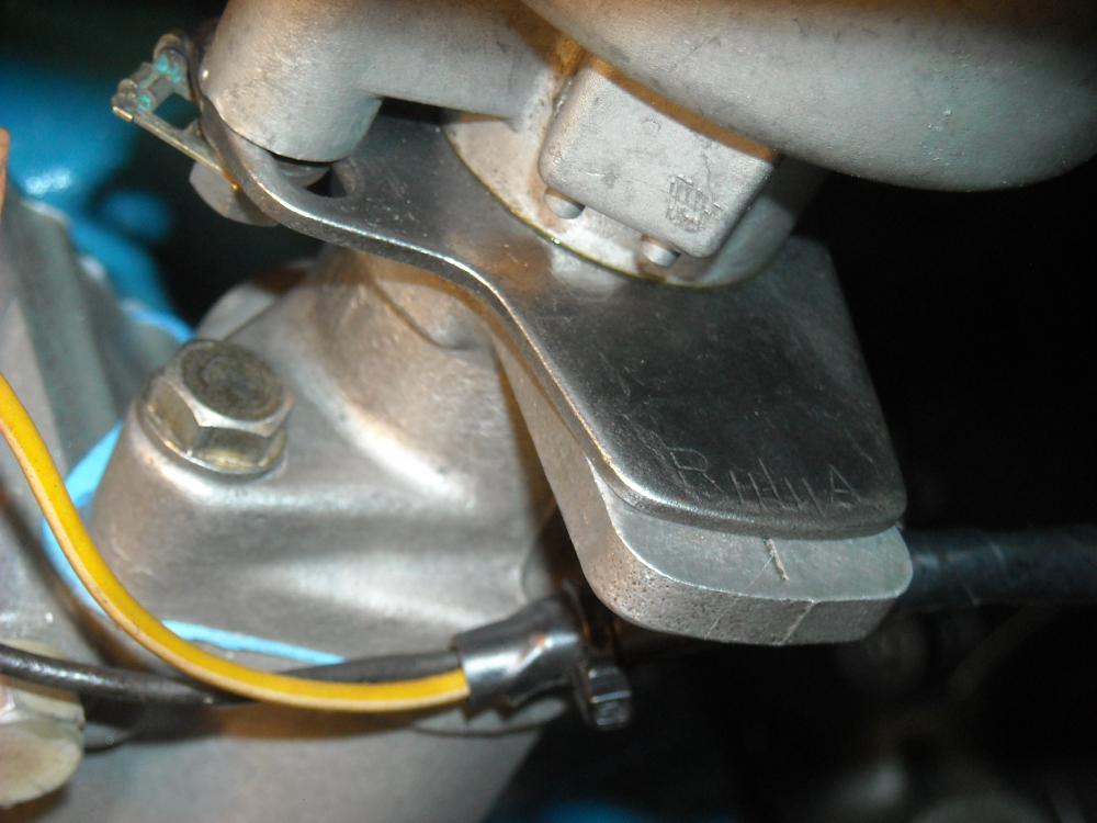
It looks like a washer but it is actually an indentation cast into the timing cover, the flash makes it look strange. So, I dropped the oil pump and re-clocked the shaft one tooth over to this, which resulted in the R/A and the underneath adjustment in the dead centre of their movement and still 10* timing. After 30 min. idling at about 800 rpm while I played with the distributor and carb balance the #1 sparkplug looks like this, The fast idle screw is still 1/2 a turn in to keep the engine from dying, not at all sure how to fix that yet and the tach is not working. The linkage is balanced so both butterflies open at the same time and the carbs are balanced at 8kg/h on the SK Synchrometer. I haven't touched the jetting adjustments under the carbs yet as ZTherapy usually has those bang on. I guess my next step is to start reading the SU forum. Chris

-
Okay, the engine roared to life this morning on the first try, always nice! So far no leaks. I set the timing at 10* with a timing light, balanced the carbs at 800 rpm (still need half a turn of the fast idle screw to keep it from stalling but I'm sure I'll figure that one out) But, the distributor is turned counter clockwise as far as possible in both the R/A adjustment and the underneath adjustment in order to get that 10* at the damper. Here the small screw driver I am holding is pointing exactly where the #1 sparkplug contact is on the cap at TDC, and this is with the distributor removed still at TDC, Even though the oil pump/distributor shaft position looks right I think I should lower it and and turn it one tooth? Would having the cam timing gear adjusted to #3 cause this? Thanks, Chris


-
Complete junk. Have a look what the guys on Hybridz have to say about them.
-
Whos turn is it to feed him?"

-
When you do finally get to the wiring harness give yourself lots of time, 2days to week depending on how much work it needs. Lay it out on the floor in the shape it normally is when it's installed. You will want to remove all the wrap so you can check for burn throughs, nicks, previous modifications and connectors that need replacing. I found it very helpful after removing the wrap to bracket with a tie wrap on either side of the harness where a wiring lead left the main harness. You don't need to pull them tight but just enough to mark location where the wires come out so when you are recovering the harness you end up with the same length of wire coming out at the right spot. There is nothing worse then doing a perfect wrapping job, go to install the harness and find it doesn't fit. Then you have do a cut and patch job on the spot or redo all of your work again. You will be amazed at how much crap can get inside that wrap after 30-40 yrs and it is not uncommon to find 5-6 wires melted together with only microns of plastic insulating them from each other. If part of a 16 gauge wire needs replacing I like to pull the entire length and replace it with 14 ga., same with the lighting harness, I have found it a good practice to up size all of those wires. Also, before doing the final wrap I have found it useful to add an additional 4-5 wires into the harness that will run from the engine bay into the cab and a few from the cab to the back of the car. Clearly mark them as dormant wires so when in the future you want to add some electrical thingy your wires are already there waiting and you won't have to have jerry-rigged looking wires poking out running across the engine bay. Chris
-
-
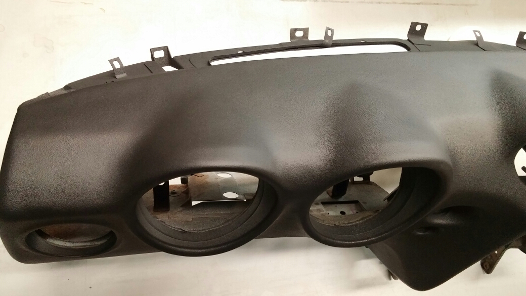
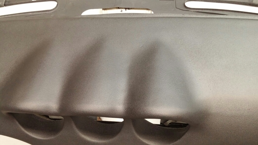
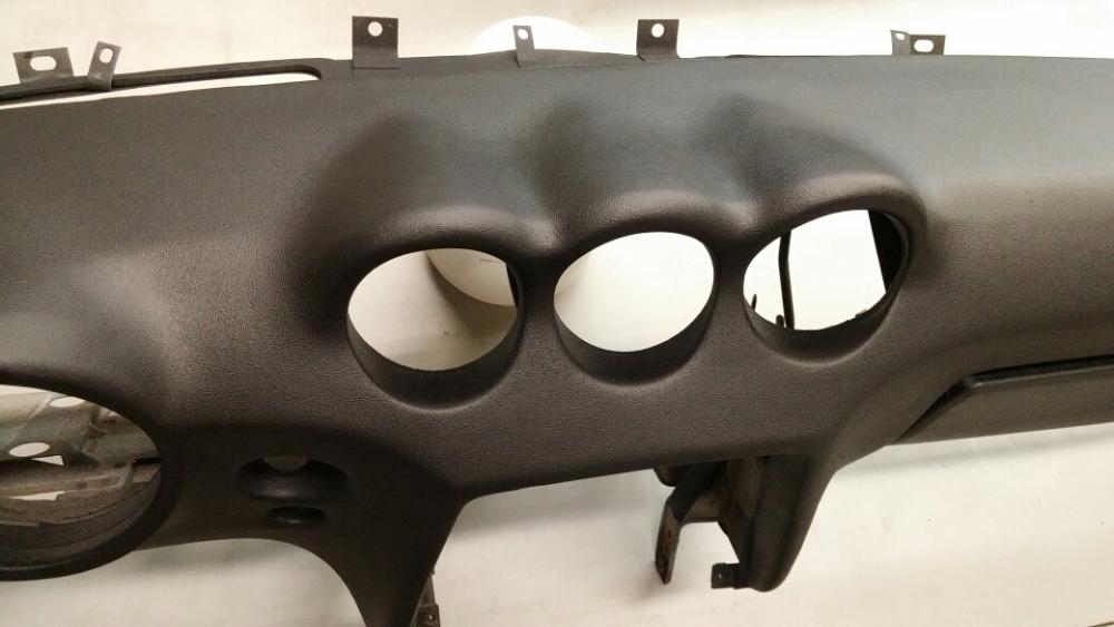
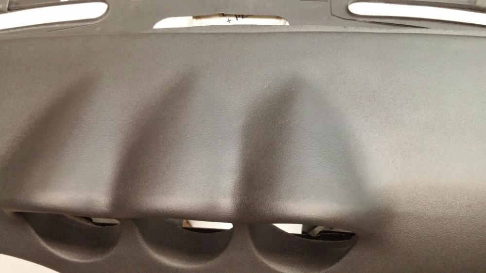
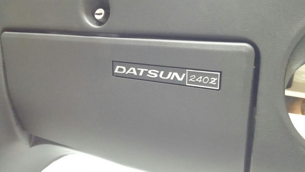
Guys, I p/u the dash today and it's just as nice as in the pics, he said he just followed SEM's instructions and that dash restoration thread that was so popular last year. I just went into the archives to find it but couldn't, there is so many. Maybe someone here has it on their bookmarked/favorites list. Chris
-
-
Wow, you went a lot farther in your research then I did. Although the sharkhide can handle fairly high temps, ultimately it may not be the best coating for engine parts due to its dislike of gas and oil. But the rest of the engine bay will probably be fine, as the weather gets warmer I'm going to start testing it on hard rubber and plastics. The glisten is a 2 part mixing process so I can't imagine that trying to repair gouges and scratches would be anymore successful then repairing chips in exterior paint. Being clear it may not be as noticeable but probably wouldn't be as smooth. Glisten does cure to a hard surface though so may take well to sanding, that would be an experiment worth trying. Chris
-
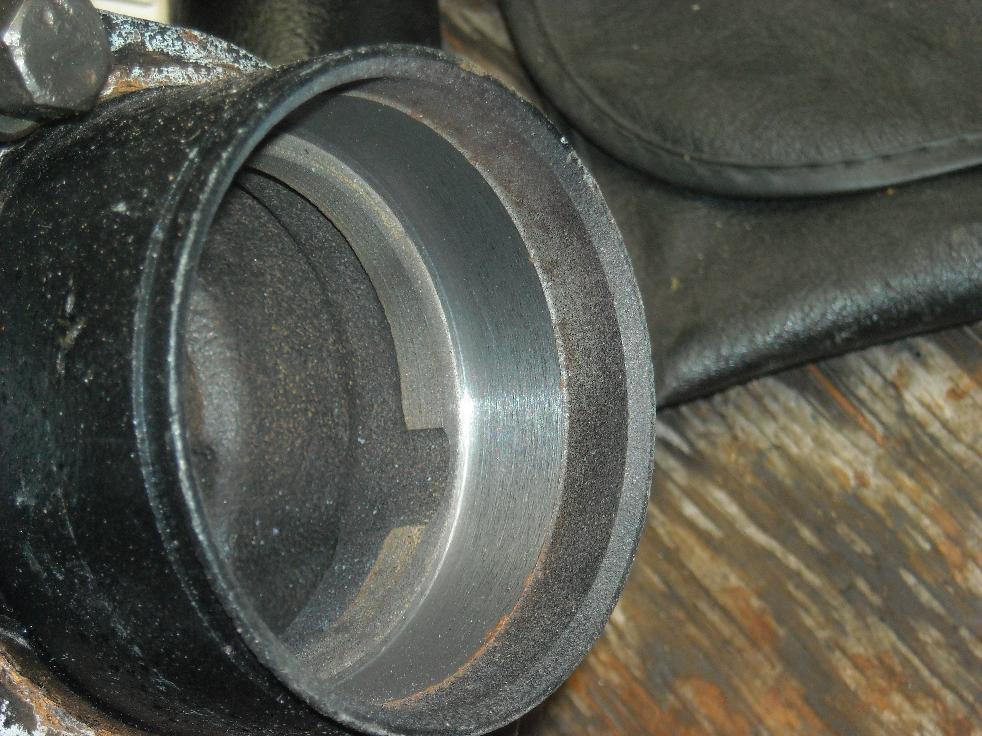
"The distributor has what seems to be a precisely machined and located mount and the slotted collar holds the top of the shaft in place below. So ti's designed as an assembly, I think." Zed you hit the nail on the head, not only does the slotted collar at the bottom of the distributor shaft locate and support the oil pump drive shaft, it does so without letting either shaft (oil pump or distributor shaft) touch the the timing cover hole. Simple but precise, pretty much sums up Datsun doesn't it?
-
I'm picking it up on Monday, I'll ask him.
-
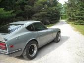
rcb280z, that yellow and black striped house in the back ground of your picture, is that one of those termite house covers so they can vapour the whole place with insecticide?
-
John, I had forgot those, what is really remarkable is they started as black. Talking about SEM products, a buddy of mine just re-finished a dash for me using the satin black.(I tried it doing it but it came out horrible) He has the patience for that kind of work, here have a look.

-
Very clever, those fuses look better than factory to me.
-
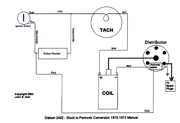
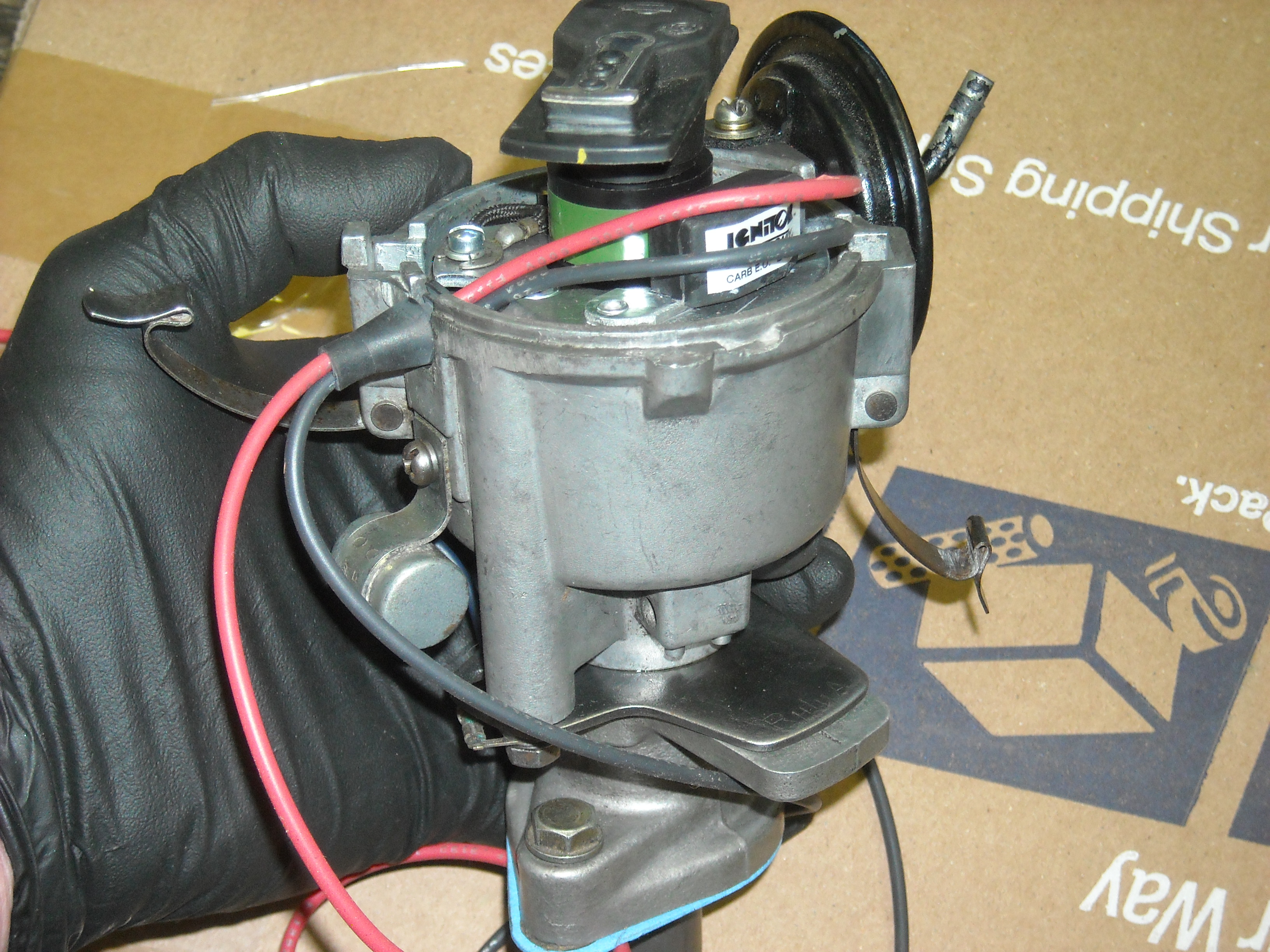
Zed, It's been 4 yrs and I simply don't remember, I wasn't in the habit of photographing everything then like I do now. Also, when I tried to get the L28 going with this distributor I had nothing but problems and chased my tail for 2 months and pissed off a lot people on this forum, so I want to avoid that this time by running things by you guys who know this stuff like second nature. So, I'll forget that diagram and just do what Pertronix says. Bruce, that make perfect sense, I'll do it that way. The shaft does lean a bit to the lower right but re-locates to the center when the distributor is lowered onto it. But now that I think about it maybe I should spin the crank by hand while watching that oil pump shaft to make sure it isn't bent. Thank you, the 2nd confirmation is nice. With any luck I'll have this running by tomorrow. Thanks, Chris
-
Cleaned this up so it makes more sense hopefully. Chris
-
-
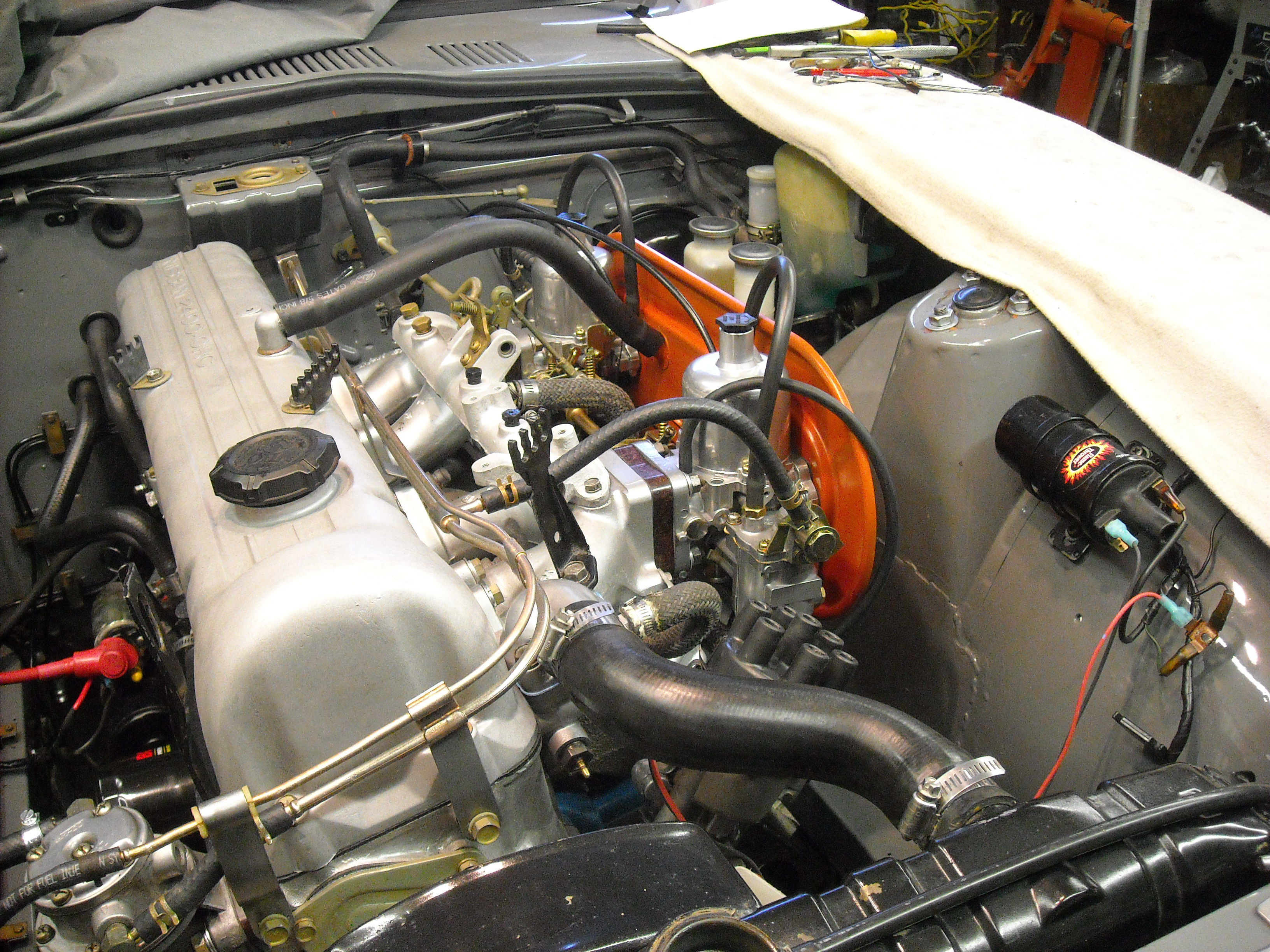
4 yrs ago I pulled the original 2.4l engine, filled it with oil and tucked into the corner of the shop thinking it would never be started again. Well, it's back in it's numbers matching car and I'm getting close to start up and I thought I would check with you guys on a few things before I start cranking. The compression was good when I put it away so last fall I got it on the engine stand, cleaned and painted it, all new seals and gaskets, the head was skimmed. So everything is pretty and lubed, the SU's were rebuilt by ZTherapy, a new Pertronix unit was installed in the original distributor that I gave a bit of an overhaul to, all hoses are new and tight. The engine is at TDC. The coil is a 3 ohm so the ballast resister has been bypassed The dizzy has 2 adjustments, one for the advance/retard, and the 2nd adjustment I'm not sure where it should be before locking it down? Also, Pertronix says put the black lead on the neg side of the coil and the red lead on the pos side but I found this diagram on Zhome.com. so I made up this connector to join the short Blk/w lead, Grn/w lead and the pertronix red lead. Any advice would be appreciated