EuroDat
Free Member
-
Joined
-
Last visited
Everything posted by EuroDat
-
 All the ball bearings and the needle bearing between input and main shaft should be replace I would replace all the seals regardless of how they look. You can check the wear on the synchros by following the procedure in one of the 71B manuals. The original nissan synchros would need to be very worn before I would go after market. Next is to check the shifting inserts and the circlips. If you can get new circlips, them I would definately get them. Remember what I wrote above. The pressure the circlip applies to the shifting inserts determines how much force the sleeve can apply to the synchro ring before the sleeve rides over the shifting insert and engages the gear. A weak circlip (or on the 71B it's 3 springs) will allow the gear to grind a little when going into gear. If you can find new detent springs for the selectors, then it would be a good time to change them.
 -
Chris, The car looks absolutly fantastic. Job well done, as usual.

-
If the bearing in the adapterplate start failing, it generally is first noticable in 1st gear. 1st being the closest gear that puts sideways pressure on it. I would expect the sound to be most audible in 1st then 2nd then 3rd and 4th being a direct drive the least of the noise. You can get noises when certain frequencies match, but 3rd gear clunking when a mainshaft centre bearing fails is one I havn't heard of before. That is why I focussed on the third gear as the area that would cause a noise in third, but noticably less in 1st or 2nd.
-
Xenonzcar doesn't have the 71A. I don't know where you can find one these days. They were available, but I never downloaddd it. You are one of the thew that wants to rebuild a F4W71A. I'm no an 71A expert, but I think the sleeves and selector forks are interchangable and the sleeves reversable on the 71A. That is not the case with the 71B.
-
Those marks are only wear marks from the circlips. That is most probably why they changed the design to springs under the shifting inserts in the B version. I don't see any serious issues in the photos. The way the syncho works is simple. This is a basic description of how they work. The shifting inserts are pushed into the outer hub by the circlip or springs. The outer hub is held in the correct position by the selector and selector detent ball/spring. The shifting inserts insert into the three tabs cut outs in the synchro ring and lock it with the hub. The synchros turn with the hub. When the sleeve moves toward a gear it pushes the shifting inserts and the synchro onto the cone of the gear. When pressure is applied the synchro will speed up or slow down the gear until its rotating at the same speed. When more pressure is applied the sleeve slips over the hump on the inserts and engages the gear. Its held in gear by the selector detent ball/spring. Looking at your photos. The hub, circlips and gear needle bearings look ok. Makes me wonder if you were not experiencing a frequency vibration that was worse in third gear and causing a rear engine mount to tap against too long mounting bolts for example. I'm not saying that is your problem, but it could be something outside the transmission.
-
The needle bearings in the gears look good. That dull colour on the shaft is slight wear, but not excessive damage. It's normal. The are actually 3rd, 2nd and 1st. 4th is a direct drive through to the input shaft and doesn't have any reduction though the cluster shaft. The photo looks like the 3rd gear needle (left side row) shows signs of blueing which could be a sign of excessive heat build up. Are all the hub, sleeve and shifting inserts ok? How was the circlip holding the 3rd/4th hub? And the end clearance to the circlip?
-
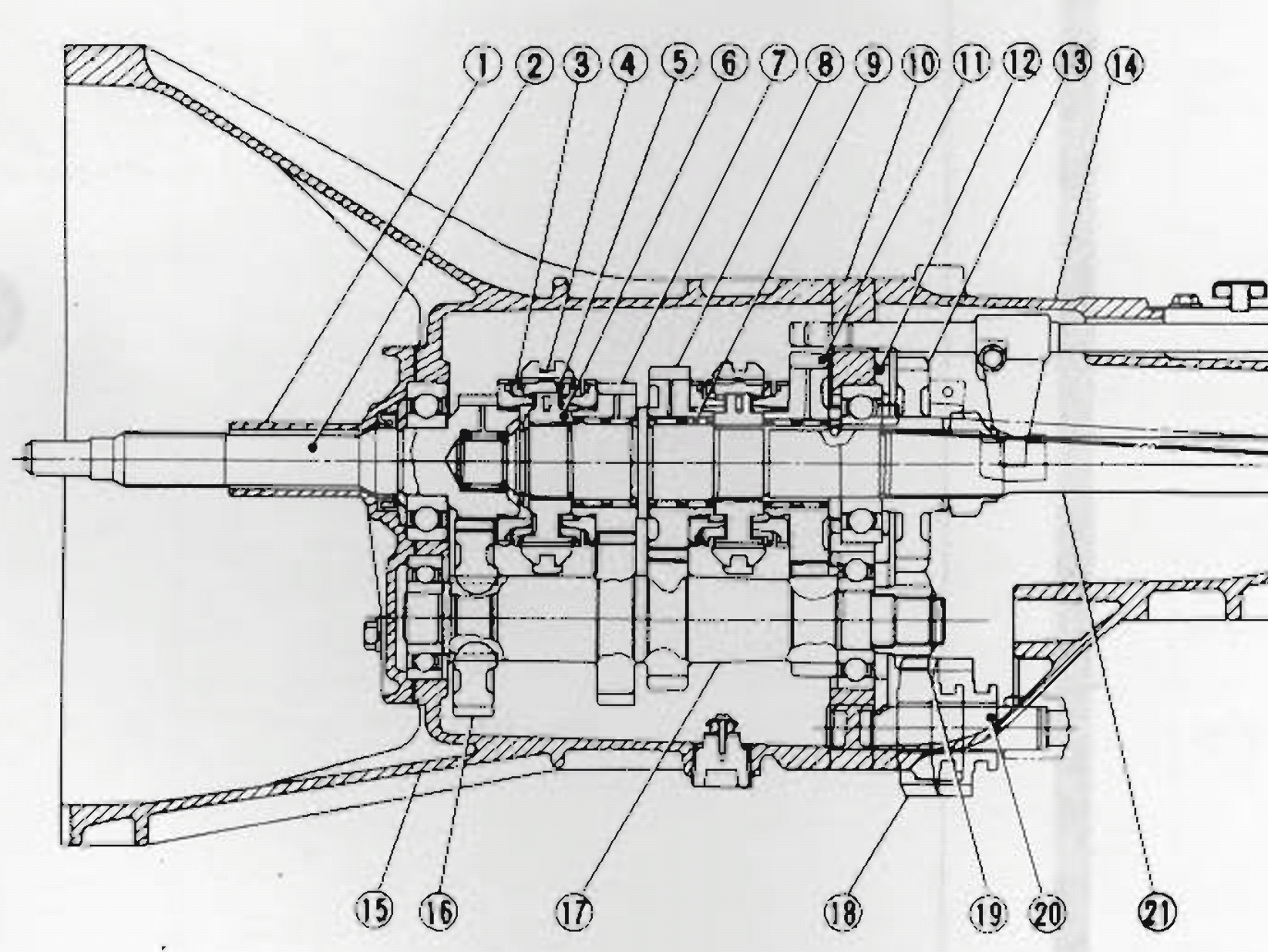
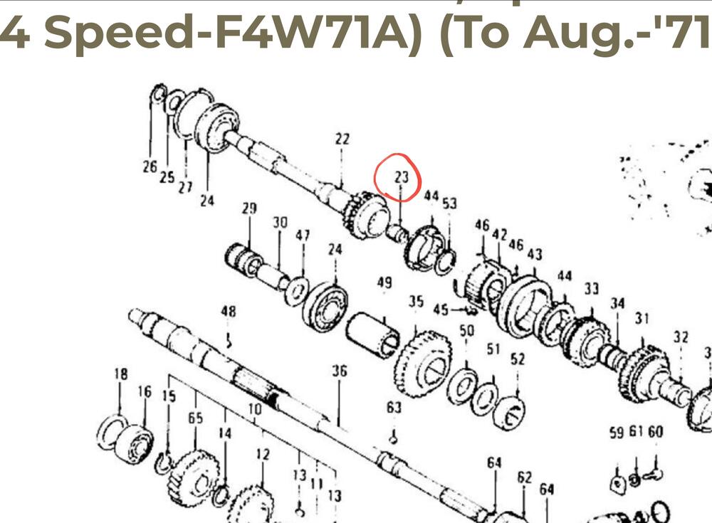
It looks like it is an issue with the third gear. Its you have no end play in the main shaft it is not the ball bearing in the adapter plate. The needle bearing between the input shaft and main shaft shows some wear, but it's not causing any problems. I'm not and expert on the 71A transmissions, but most of the components are very similar to the 71B used in the 720 trucks and the later Zeds. The next step I would take is to dismantle third gear. You will need to remove the cluster shaft front bearing and front gear, which is held on with a circlip, to be able to remove the input shaft. Pay particular attention to damage around the circlip holding the 3rd/4th gear hub on the main shaft. I have only seen it happen once, but the circlip came off and the hub could move back and forth. That made some serious clunking sounds only in third. It was also making some much quieter noises in 1st and 2nd. That happened after a guy did a home rebuild and when it started clunking he bought it in to have checked. I wouldn't expect this from the factory, but these cars are old and many repairs later.... The 3rd/4th hub and sleve are pos 4,5 and 6. The gear pos 16 needs to be removed from the cluster shaft pos 17 to remove the input shaft pos 2.
-
I have some questions and test, but now the transmission is out and dismantle, I hope you can varify some. 1. Was there enough clearance between the tunnel and monkey motion when in third gear? Sometimes the selector stick can hit the bodywork, mostly after some kind of modification. 2. If you held the gearstick, did the sound change in tone, reduce or stop? 3. Was it always in third through the whole rev range? Yes the frequency will increase with revs, but did the cluck maintain the same? Clunking at 1500rpm was dubbled at 3000rpm. 4. Was the clunk during full acceleration, coasting and de-acceleration? Did it change ?
-
The bearing is ok. Your problem is elsewhere and now to find it.
-
I now have read through this thread and what you are describing sounds like a failed neddle bearing between the input shaft and the main shaft. 3rd gear puts the most strain on that needle bearing. If it starts giving problems, then 3rd will show it first. It will be interesting to see what the bearing looks like.
-
Hi AnvilZ, The movement you show in the video is not a problem. It is normal for the input shaft to move back and forth like that once it is removed from the transmission case. The input shaft is actually held in position by a outer circlip on the bearing. You removed the circlip to dismantle the transmission. The main (output) shaft should not move like that. If it does, then your centre bearing in the adapter plate has collapsed. The bearing kit for the FS5W71B will not work on the F4W71A. Different bearings. I have the bearing numbers somewhere, but it has been 7 or 8 years ago since I last needed them. I will see if I can find them for you. You can also dismantle the transmission and take the bearings to a local bearing supplier. They are common bearings.
-
I was led to believe that the filter would bypass at around 7 to 15psig (0.5 to 1.0BarG). If the differential pressure reaches 7 to 15psi the bypass will open accordingly. It is just a spring valve and not a calibrated releif valve. It is not uncommon for a percentage of the oil to bypaas the filter depending on viscousity, oil temperature, pumped volume and degree of clogging in the filter. The oil pressure (85psi) you are reading doesn't say much about the bypass. A new engine can have higher pressure due to the finer tolerances creating more backpressure. I think I would cut the filter open and check to see the filter I'm using does have the bypass function. Most do these days, but just to be sure.... If it does, then leave it at that and keep using that brand and type of filter.
-
Yoh can read this one too.
-
Like zKars said, there is a thread that details methods to remove it. I have used a small massive hammer, one with as much weight as possible and small. Unscrew the nut until it is flush with the end of the thread. Tap it with the hammer until it comes loose. If it won't release than add heat to the striking lever area around the pin and tap it out. Don't heat the pin. You wont the lever to expand, but not the pin itself. If you damage the pin, you can still get them through Nissan or local parts store. I think the size is 9.5mm IIRC. Ask for a 9.5mm cotter pin.
-
If you are using a Fidnaza flywheel it wont make any difference which pressure plate you use. Both the 225mm and 240mm will fit the Fidnaza flywheel. The 240mm pressure plate has 9 bolts, but I have heard only 6 are used on the Fidnaza flywheel. I am using a 280ZX 2+2 (240mm) lightened flywheel to about 16lbs and a stansard 240mm clutch. Works great and has a light feel.
-
Thanks for sharing. I can only fit the belt on my hitachi compressor by removing the adjusting pulley, fit the belt and then insert the adjusting pulley and retighten. The tensionef is then about half way when the belt is tensioned. My belt may be one size to small.
-
Well done. I like they way you managed to keep the original bracket and adjusting pulley. I have seen other aftermarket options where the compressor moves to tension the belt. Not much space down there for that kind of adjustment.
-
Hi Dave, Just went through my notes and you are correct. I found a formula: R12 charge x 0.9 - 0.12kg = R134a charge. It is an approximate calculation and generally results in 70 to 85% of the original charge. Ex. 1.2kg R12 x 0.9 = 1.08 - 0.12 = 0.96kg R134a (80%) Like I said, NO expert here......
-
I'm a bit like the Captain. Any advice I would give wouldn't end well. I want to restore my AC and interested in what you guys (Cruzzar and S30Driver) do to restore yours. I didn't know they changed from a high pressure to a low pressure switch. Low pressure must have caused more problems than high pressure, so they change somewhere in the 280ZX model. What I have learned in my research and meager training in an oil refinery job 25 years ago, but that was R22 and ethane compressors in a hydrocarbon extraction plant making ultapure hydrogen to gas chromatographs. R12 has a lower condensing pressure than R134a and therefore requires a smaller condensor. Most (larger) american cars have fairly large condensors so generally not an issue, but european and japanese cars can have problems converting the gas to liquid in the smaller condensor and greatly reduce the efficiency of the AC. Tha R134a molecule is smaller than that of R12, so a system that didn't leak with R12 could start leaking with R134a due to the smaller molecule and higher discharge pressures. R12 uses mineral oil which is not compatable with R134a. The system must be thoroughly flushed before using R134a. The system can than use polyalkyle glycol (PAG) oil. Their is also a polyol ester (POE) oil. The dryer must be replaced and should be replaced every time you open the system. It is improtant to remove all traces of water. R12 would tolerate small amount and eventually move it around to the dryer, but R134a systems the PAG oil is hygroscopic and R134a than converts it to hyrofluoric acid which will damage the hoses, compressor etc. Not sure if there are differences in the original dryers and the ones you can buy now. A R134a charge is about 75% more than the R12 charge in the same system. My plan based on my meager research was to remove the system flush all the components, rebuild the Hitachi compressor (found a revision kit on www.marktplaats.nl here in NL), replace the hoses, reassemble and pressure test with air for a month or so. Than install a new dryer and recharge the system. I am hesitant to go ahead and that is why I'm interested in the approach others take to get there systems operating again.
-
Looks neat and clean so far. Nice work. The red you see on the 280Z indicator mounts will be covered when you fit the indicators and their shrouds. It will look neat and tidy when it is finished💥. Just repeating some of what we messaged for the benifit of other members: The 280Z has a larger air gap between the bumpers and lower valance for the larger radiator. If you can fabricate two extra bars in the bottom grill, it will fill the gap nicely. Or the Skillard 280Z grill. Be aware when ordering because they make the 280Z grill with 12 horizontal bars and 10 horizontal bars. The 12 bar version does not require the original lower two bar grill, but the 10 bar version does. I would suggest the 12 bar version and avoid any mis match issues. My bumper and grill brackets will only work with the Skillard 240Z grill.
-
The sizes for these two parts are: The seal is a 14/20 x 4.2mm NBR Lip seal (ID/OD x thickness) And the O-ring is 24x2.5mm (IDxCross section)
-
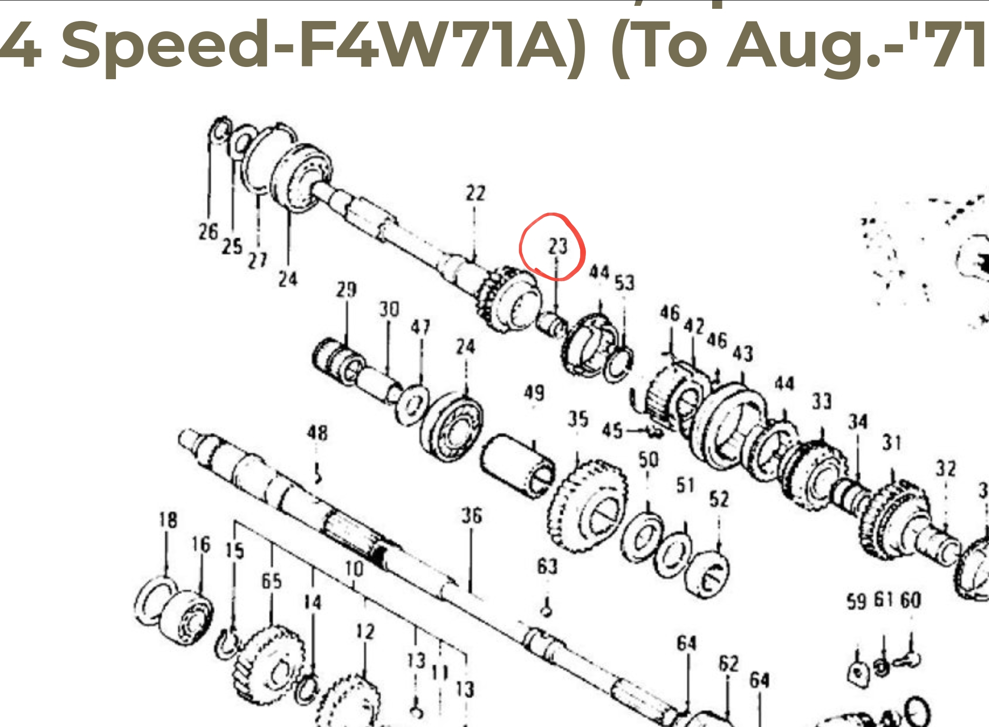
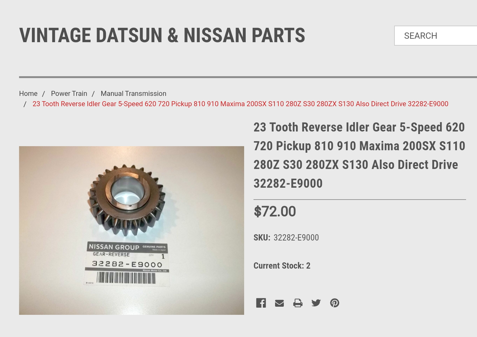
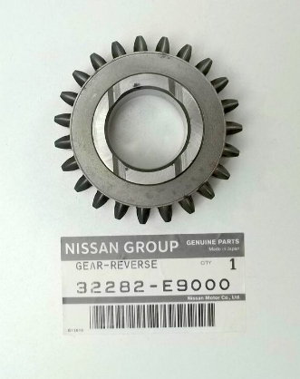
Hi Charles. @Patcon I'm not sure how far you are with Codys tranny, but I found this in my weekly search. http://datnissparts.com/23-tooth-reverse-idler-gear-5-speed-620-720-pickup-810-910-maxima-200sx-s110-280z-s30-280zx-s130-also-direct-drive-32282-e9000/

-
It should not be too much a problem. The outer circumference has more resistance area and no lube causing more resistance it's unlikly to turn. If you lubricated the inner contact surface then you should not has any issues.
-
My old bushing was just like yours Charles @Patcon with the same locking tabs. I have seen this style in the 71B. Can't find my old one anymore. I checked the spare 71C I have and it is hard to see with the main shaft in place, but it looks like it's slotted (2 holes) like Dave WM described. I know the originals had no holes, but later the did. Can't remember exactly when, but I thought it was in the 280ZX when they changed. Most probably after 82 because the 82 close ratio I have had the old style as well.
-
I wouldn't drive out the brass bush. Never heard of one needing replacement and you would need to get it fabricated. All I use is a length of 2.5 or 3 mm welding rod, with flux removed, and flatten (to about 1.5mm thick) the last 5mm with a hammer on a vice or anvil. Then bend the last 3 to 5mm to 90 degrees. Use it as a hook. You can get that behind the seal and pull it out. They should come out easily unless someone has glued it in. Yours looks like the last person to rebuild the transmission put it in backwards or it could be the photos. The lip in the seal should point towards the transmission.