EuroDat
Free Member
-
Joined
-
Last visited
Everything posted by EuroDat
-
 Hi Charles, Looking at your photos, you have the earlier fibre synchro ring for 5th gear. That part number I quoted is for the later version 71B and 71C in the 300ZX. You will need the manual for the 280Z 1977. The manual for the 280ZX wide and close ratio has the later type synchro on 5th gear. The part number you will need for 5th gear synchro is P/N: 32361-20100, but it has been NLA for more than 15 years. If 5th didn't have any problems, you should be able to use it again. The original p/n for the 1st to 4th synchro was 32611-14600, but has long since been replaced by 32604-P0100.
 -
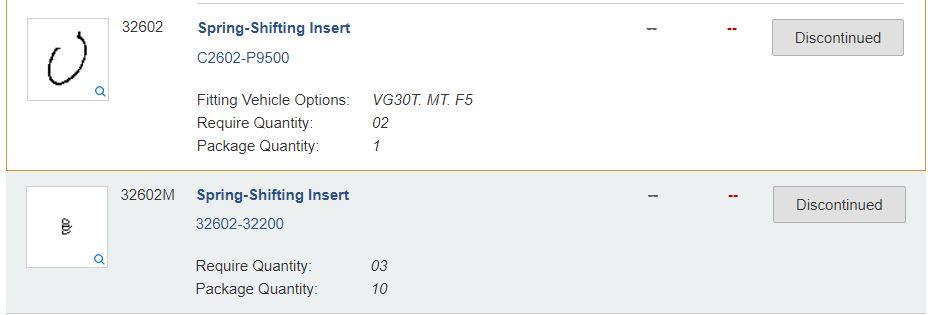
Just for clarity, I updated the parts list in the resources sections. I came across an alternative for the shifting insert springs. If you can not find the little springs, some aftermarket companies supply an alternative circlip (set of 2) with p/n: . I think they come from a Chevy transmission, but can't confirm that. Not sure how they perform compared to the originals, but it is an alternative.
-
Hi Charles, Most important before you strip it down is to check end play on all the gears. You can not check it properly once you dismantle it. The clearance varies per gear, so check the manual for the tolerances. If it exceeds the maximum tolerances, you can fix it by replacing the gears or a machine shop. The clearance on the baulk rings can be checked after dismantling. They should have a clearance of 1.25 to 1.60mm. If they are getting close to 1.25mm I would consider replacing them. It's one of the clearances that effects the way changing gears feels. If you do need to replace the baulk rings, I would strongly suggest using the genuine Nissan parts. Yes, I'm sure there are aftermarket units out there that will perform as well, but there are a lot that don't and I can't tell the difference through a simple photo on a website. The next important thing to giving your transmission that new snappy gear change feeling. Replace the shifting insert springs on both hubs. There are 3 in each synchroniser hub. P/N: 32602-32200 The other springs that should be replaced are the checking springs in the selectors and the return spring behind the return spring plunger. The reverse gear does look pretty shabby, but if you can't find another to replace it you can "repair" it. The most important thing is that the teeth are clean and not chipped. You can have the reverse gear machined back until the teeth are cleanand bevel the ends. Not cheap, but if you have nothing else it will work fine. The only thing you will notice is your gear stick will travel just a little further before reverse engages. If you need help on this, I can explain further. First choice is try and locate a replacement.
-
No problem. Your bracket with that v-belt looks like it's positioned the compressor very well and still giving you good clearance between compressor and frame. You might want to do some research on the hose fittings. If you get the 90degree elbow instead of the curved elbow, it will give you more room to move and adjust the compressor. https://www.summitracing.com/parts/fss-15211 https://www.summitracing.com/parts/vta-354300
-
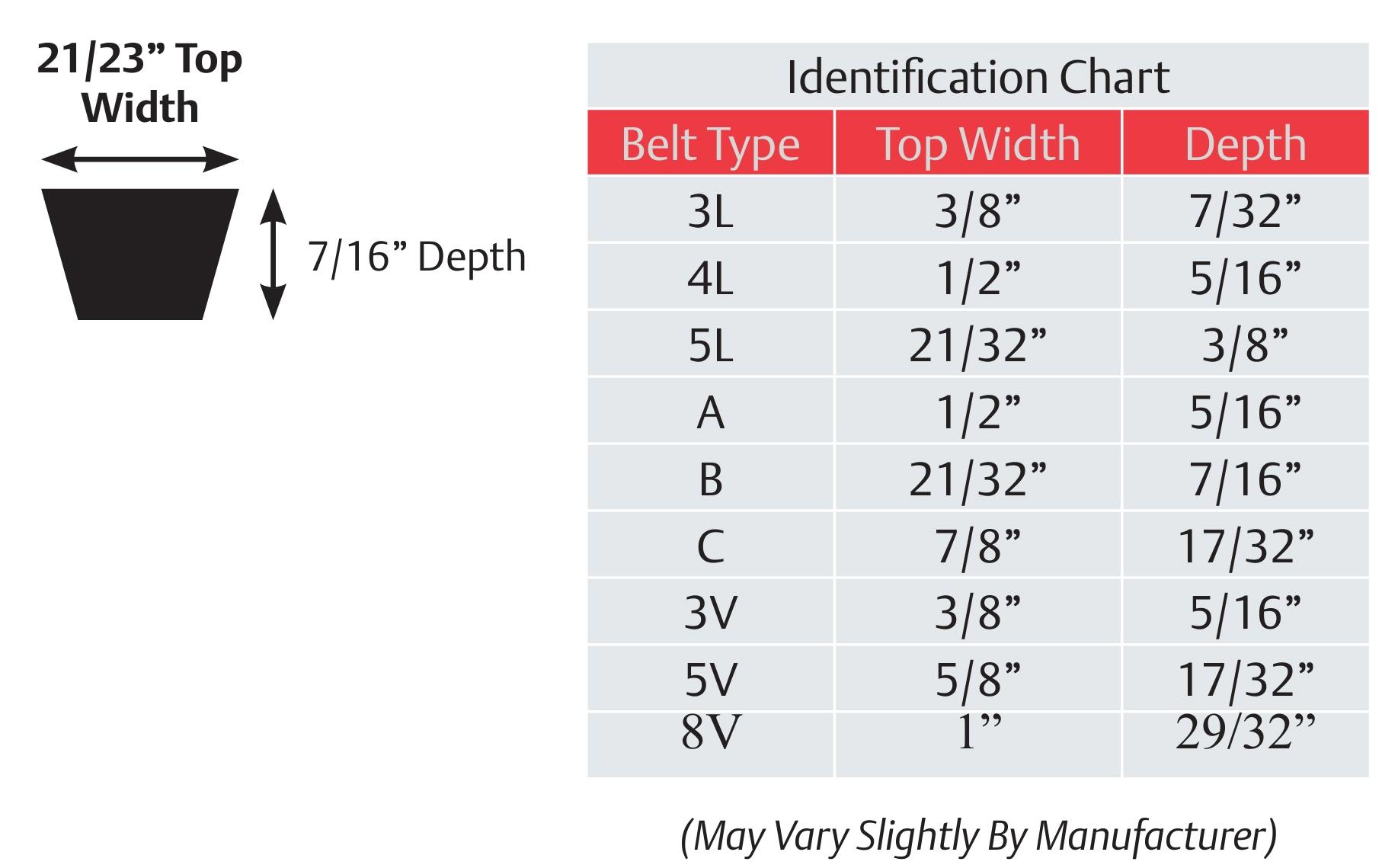
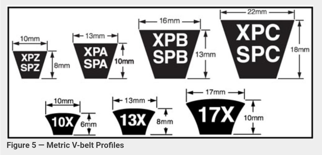
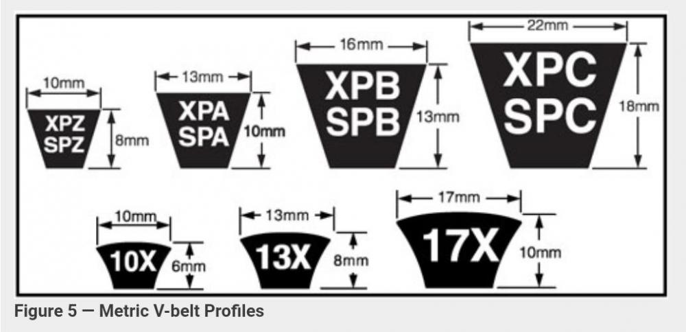
It is a challenge to design a good working adjustable compressor bracket. Most systems that use an idler pulley do it for two reasons. 1. Adjustment. The larger the V-Belt section the deeper the belt is and requiring more movement to replace the belt. The larger the adjusting pulley is the more movement required to release and replace the belt. For example: The fan belt is a A or SPA section belt with a length 900mm. The belt is 10mm deep and the alternator pulley has a small diameter. To remove the belt you will need approx 20mm to release to belt get it over the pulley groove and apply the correct tension. The alternator is easy to move and it has no big hoses sticking out to hit things. The compressor on the other side uses a B or SPB section belt (13mm deep) and has a large pulley requiring more adjustment to remove the belt. The compressor is bigger and takes up much more space. The hoses stick out and don't give much room for adjustment or they have to be long enough to allow adjustment and still have enough freedom to compansate for engine movement. The compressor adjustable bracket doesn't move the compressor directly away from the crankshaft, but in an arch requiring more movement. Its easier to move a small idler pulley 50mm than the compressor. 2. Tension. Applying the right tension to the fan belt is easier because it is a small section belt and the alternator is accessable. The compressor requires more power therefore uses a B or SPB section belt with a greater contact area. They also have a higher tension. The idler adjustment bolt is easier to set belt tension. Not trying to take anything away from the PO's initiative, but these will be some of the challenges he will face. All solvable with enough R&D. Choosing the right length belt will be important and routing the hoses to give yourself enough room to adjust the compressor.

-
They both look very salvagable. They look very rust freeish. I don't think a completly rust S30 still exists. The salt air during transport to the states was enough to start the process. Good luck with your offer. The carbs are round tops so the model is pre Aug 72 or around that month. There always seems to be exceptions to the rule. The white one has water piping to the intake manifold so it should be the 3 screw version. 4 screw round tops up to July August 71 3 scew round tops up to August 72 (water heated) Flat tops up to 280Z.
-
If you pull the plug on the origjnal TIU and the tacho still jumps around unchanged, my bet is a faulty (matchbox) TIU on the distributor. You could still check the resistor tobe sure. Like zed head said, it's under the passenger side dash section, taped into the harness.
-
It is doable. The cold start function only runs while engine is cranking. If you ground thenegitive bullet connector the csv will always activate while cranking. May I ask why you want to do this?
-
Yes you will get power out both bullet connectors. What's happening when you crank and test with the test light is the positive is also passing through the coil in the csv. If you disconnect the csv connector you should only get power from one bullet connector. The other bullet connector will be the ground circuit for the csv and the (-) signal to terminal 21 in the ecu which tells the ecu the csv is active.
-
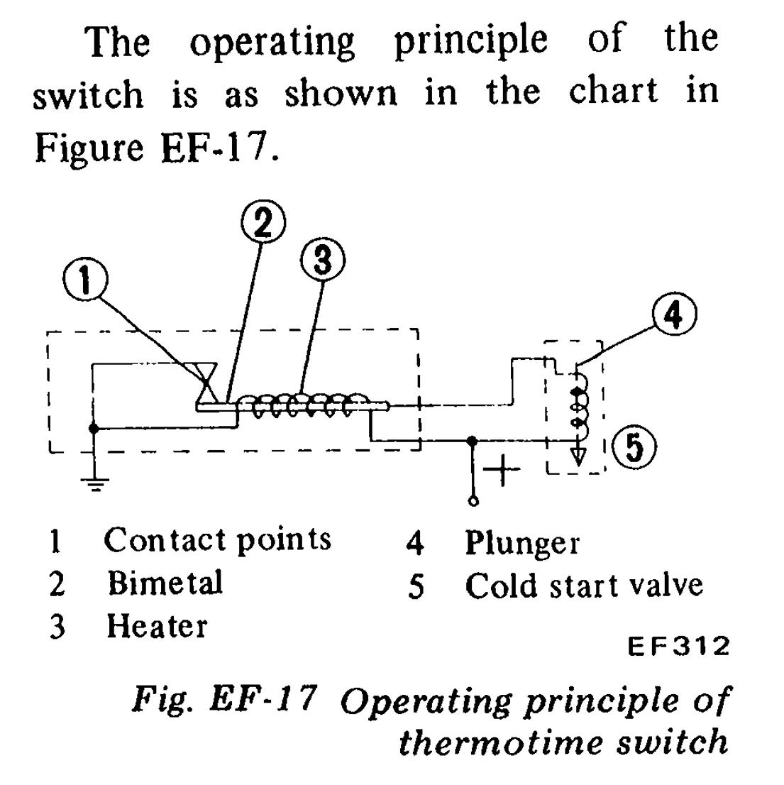
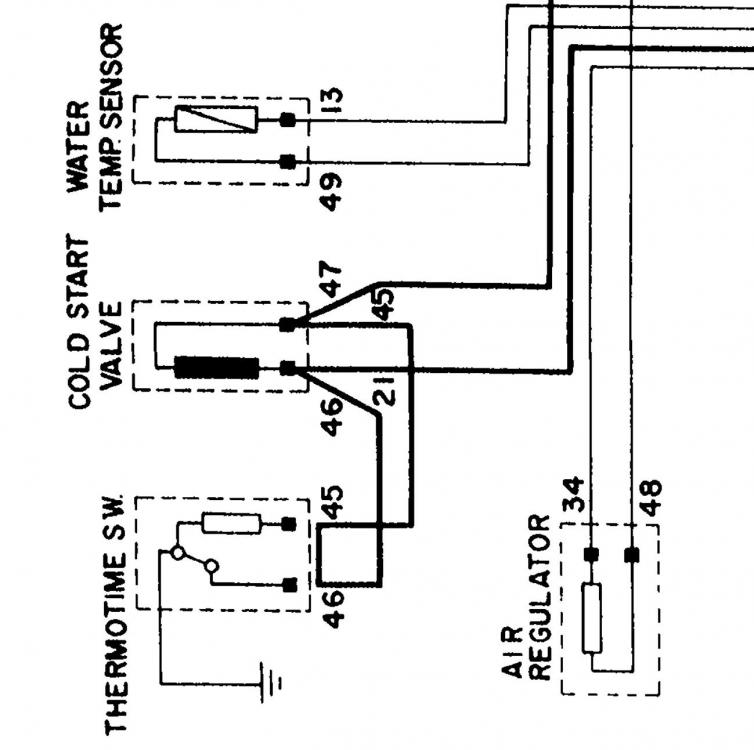
I don't think it will work that way. The therotime principle works so: Power comes from wire nr. 47 when engine is cranking. From 47 it goes to the thermotime via wire nr 45. The power to the thermotime powers a coil around a bi-metal strip. That in turn will heat up and open the ground circuit. The thermotime provides the ground via wire nr 46 for the csv through its internal contact switch. The contact switch is there to stop you flooding the engine while repeatably cranking for long periods. Bridging those two thermotime connector wires is a diagnostic test to see if you get battery voltage at terminal 21 on the ecu plug. To test the csv you need to identify the power pin for wire nr 45 in the thermotime connector. Disconnect the thermotime and make a connector wire to the other terminal wire nr 46 in the connector and run it to ground. This will bypass the thermotime and give you a ground for the csv. Then crank the engine. It should work, being all the other components are working. If it works your thermotime is defect. Hope that makes sense. The wiring diagram makes the thermotime function a little blury. I think I got it right.

-
The 280ZX dizzy has the TIU fitted on the side of the distributor which is btw not a good spot for it. All the 280Z models had an external TIU located in the passender sideof the cabin, near the fuse box. You have the 78 which has a simple 6-pin connector. When you install the 280ZX distributor you must disconect the old TIU. You need to disconnect the 6-pin plug. Is blue wire connected to the coil negative? The blue wire was the trigger from the TIU for the coil, but now it only communicates through a resistor to the tacho. If your engine is running properly and the tacho was working before the swap, then it is probably one of these two things. Not likely to be the resistor, but you should still check it if it is open circuited. A dodgy Matchbox TIU will work the tacho, but it will generally be erratic and bouncy. It oftens drops to zero and jumps back up again and all over the place, but it will generally do something.
-
The air gap is important on the 280Z pickup. If the voltage generated by the pickup can not reach 0.3volts the HEI module will not activate. A wider air gap will reduce voltage. These pickups at best will generate 0.5 to 0.8volts at cranking speed. The later 280ZX distributors have a better designed pickup which will produce much more voltage at cranking speed.
-
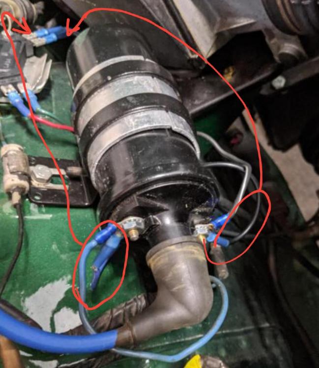
I can't follow the wiring in the photo, just going by the colours. Coil negative goes the HEI module terminal C and 12v goes to HEI terminal B. The green and red are correct. PS: Good to hear you found the problem.
-
That is a nifty 👍heat sink you fitted to the HEI module. One thing that can destroy a Hei module is poor grounding. It grounds through one of the mounting screws. Do you have good contact to the car body under the heat sink? When I started playing with this idea, I used an el cheapo test unit. I ordered two and they both lasted about a week each. The Pertronix HEI module has been in there since without any issues.
-
Well, lets see. Trying to look on the bright side of things. With the prospects of this 260Z not being salvageable, my zed just increased a little bit more in value😁
-
Zed head is right. It's a lot of trouble. Most people wanting a limited sip dif go for the Subaru R180. That might be an option for you to investigate. Subaru R180 basic requirements: 1.Subaru R180 liimt slip diff. 2. Wolf racing half shafts. 3. The pinion flange from your 240Z R180 fitted to the Subaru R180 4. I think you need to swap the diff covers as well. Long time ago and can't remember the details all too well. Here is a thread about the Subaru R180 conversion. http://www.wolfcreekracing.com/index.php?option=com_content&view=article&id=22&Itemid=31
-
Hey Zed head, It is a rare transmission these days. Knowing what I know now, I should have taken photos and made a lot more notes when we rebuilt it. I think the designers were constantly improving along the way. The reverse lock out could very well be an adition in the timeline of that early close ratio. I noticed in your link they quote 32180-E9803 as a replacement for the 32180-E9801. That means there are at least three versions of the lock out assembly. In the 71C (300ZX european parts cat.) they quote 32180-55S11 replaced by 32180V5000 and then 32180V5001. I have both the 71C and 71B. Next time I'm playing with the transmission, I will check to see what the difference could be.
-
I have only come across one of these early close ratio transmissions and it had the reverse lockout assembly. The 280ZX was an early european 280ZX and from what I can remember (back in 2013) it was a Feb 1980 model. It could be somewhere in that early version that they added the reverse lockout assembly.
-
I wouldn't be to concerned about the front bellhousing section. There are a lot of different "interchangable" castings. You can even use thd front section from the F4W71B with no modifications. Reserve lockout assembly: The early model close ratio also had the reverse checking assembly with p/n: 32180-E9801 and the later version of the close ratio used p/n: 32180-E9802. Both assemblies are interchangable, but the later version uses a stronger spring. Both parts are NLA through Nissan.
-
They will fit, but you may want to consider the pros and cons first. If you change to these PU bushing the diff noise will be more noticable in the car. It will also transfer the vibrations in the driveline tothe body a lot more. The originals are no longer available, so if they are worn and loose, you will need to replace them and these will fit fine. If you do. Remove the old rubber by heating around the outside of the mustache bar and use a pair of vice grip to twist the centre piece of the original rubber bush. When the heat works its way through, the bush will let go and twist out. You DO NOT need to heat the bar red hot. Don't heat the centre metal tube in the rubber bush. Just keep warming the outside while twisting until the bush lets go of the outer housing. If you do it this way you will have minimum toxic fumes.
-
Thatis because you have the later version. The version for the F4W71B and 280Z F5W71B is not what you see on most of the websites. I don't think it is still available. The later version 280ZX F5W71B and the F5W71C that had the non electronic speedo have the locating bolt under the speedo adatpor. You bought an adapter for those transmisions. All the seals and pinion will fit your adapter, but I don't like your chances of getting the inner seal out without damaging it. It is a simple fix. The groove for the locating tab and M6 bolt is on the wrong side so you can make a new groove or send it to a machine shop to make one. You can make a groove yourself by carefully cutting a groove with a hacksaw and fine tuning it will a small metal working file. Buy a file that fits easilly in the original groove. Remove the outer o-ring seal and tape over the ends to prevent shaving entering the adapter. Don't go too deep or it will allow the adaper to turn and the gears will loose contact. You can test if it is deep enough by fitting it to the transmission (without o-ring or pinion gear) then fit the tab and bolt. Take little steps at a time. Too far and it is ruined. Tip: To check that you are exactly opposite to the original groove. Use two too straight edges like a ruler or back of a hacksaw blade. Place one in each groove so they extend out the same direction. If they are parallel to each other, then your new groove is exactly opposite. I wouldn't use your original adapter without replacing the inner seal.
-
Another thing to look out for with the clutch master cylinder is the poor quality assemly work. The parts are good quality, but the pre-assembly cleaning is not. You often find metal shavings left over from machining the cylinders. This can destroy the rubber cups and cause early failure. It is recommended to dismantle the master and slave cylinder and clean them thoroughly before use. Do not use gasoline or aggresive degreasers, but use a simple brake cleaner spray can. Assemble with grease suitable for EPDM rubber. A lot of people don't realise the brake and clutch systems use EPDM rubber where the fuel and radiator systems use NBR or FKM fluoropolymer (viton). EPDM does not go well with gasoline. While you are at it, it would be a good idea to change the clutch hose. It generally doen't endure the forces and movement the brake hoses go through, but it can age over the years.
-
Did you pick up a slave cylinder for your clutch system? I can only see the master cylinder in the Z store link. You can use both types of slave cylinder and they will work perfectly. You have the early model clutch fork with the hole through it, so you will need to re-use you push rod in the later type slave cylinder. If you do use the later version slave cylinder, do not use the external spring. The slave cylinders function a little differently. Early type with manually adjustale push rod and return spring: The spring pulls the pushrod back until the slave cylinder piston bottoms in the slave cylinder. Setting frre travel is done by adjusting the push rod until there is no free travel and then turning the nut 1.5 turns back. The throw out bearing is free from the pressure plate. Later type with fixed length push rod: The slave cylinder has a small internal spring that applies a small amount of force on the push rod. The spring has a free length of about 25mm. Normally you can apply pressure on the clutch fork with your hand and the push rod will compress about 10 to 20mm depending on clutch plate wear. When you release your hand it will return to its rest position and take out all free play in the clutch fork. The throw out bearing is always in contact with the pressure plate. If you use the later version, adjust it by bottoming the push rod and adjust the nut until the distance between rest position and bottoming is about 10 to 15mm. You will never need to adjust it again, the clutch disc will be long worn out before the 10mm free travel is gone.
-
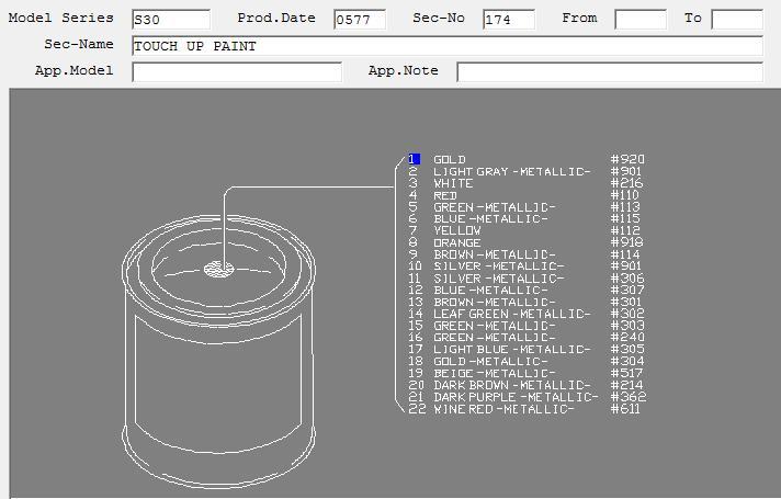
Someone probably replaced the decal and order the wrong code. 304 is a metalic gold colour. https://www.zzxdatsun.com/catDecals.php
-
Looking at the rag, the oil looks like it needs changing. The sludge on your drain plug is normal. No chunky pieces.