Wade Nelson
Member
-
Joined
-
Last visited
Everything posted by Wade Nelson
-
Help, webmasters! I was trying to log in as wadenelson instead of wade nelson and couldn't get in for weeks!! No contact address for webmaster here! No password recovery! Couldn't even estalish a new account and start over! Geez, why does it have to be so tough! What is this, the CIA or NSA? No, it's a Z website! You know, sometimes we travel, our REGULAR PC craps out, we have to use a friends computer, etc! I couldn't even get a reply from anyone! Haven't I earned that? Wade Nelson
-
Tip: Vise grips are available in two jaw styles. One for gripping flat things, the other for gripping round (or rounded off things). You'll have MORE success using a pair with the correct set of jaws.
-
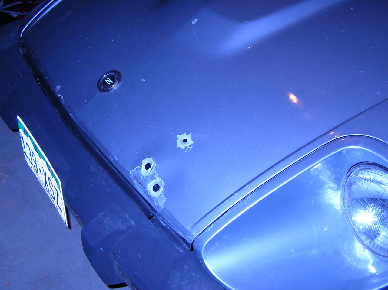
Can anyone CONFIRM the location of the fuel pump CONTROL relay on a 1980 ZX? Not the fuel pump RELAY, which is under the dash, passenger side, kick panel But the fuel pump CONTROL relay. (designated: Fuel Pump Relay-2) in the schematic. The EFI bible APPEARS to show it in the in-engine bay relay block. The diagrams are wrong for my 1980, for starters I don't have an automatic transmission but I have a relay in the socket labeled "Inhibitor Relay, A/T", I have three sockets in the rear row, not two, although only two are populated, etc. Here's what's interesting. With that relay PULLED, when I turn the ignition to the on position the fuel pump runs. With that relay INSERTED, the fuel pump doesn't run unless I turn to CRANK (I have the wire to the starter pulled so it doesn't actually crank, also allowing me to HEAR the fuel pump running) This is the same intermittent behavior I've had a few times --- hearing the fuel pump run simply when I went to ignition on --- suggesting this relay is failing According to the diagram, this behavior is IMPOSSIBLE with the relay removed. The fuel pump can ONLY receive power by way of that relay. Removed, there should be NO WAY the fuel pump relay can receive power, not in a million years. Ok, so here's my current GUESS: There IS no "Fuel pump relay -2" as drawn on the diagram. (It would be a very fancy, and expensive relay with two separate coils actuating two different sets of contacts... INSTEAD Nissan wired two "generic" relays to "build" a circuit which operates LIKE "fuel pump relay -2" would. That would explain why I have a second relay, despite NOT having an automatic transmission. Such an arrangement COULD explain the fuel pump relay getting power when only HALF of the circuit is plugged in. Now I've got to come up with a test to confirm my suspicion......tomorrow. It's late, I'm tired and hungry. Maybe now some of you can begin to understand why I put five bullet holes in this car!


-
http://www.classiczcars.com/forums/thread39295.html And if your prop starts wobbling up and down, I suggest you pull over and call a tow truck.
-
It's been a long time but I don't believe the two plates are separable. If I'm remembering right, they will rotate relative to each other a total of about 40 degrees. If I recall correctly they're peened together on a hollow shaft through which the disty shaft goes.
-
http://www.ebay.com/sch/sis.html?_nkw=CARDONE+31+607+Distributor+ http://www.autopartswarehouse.com/shop_parts/distributor/nissan/240z.html http://www.autopartswarehouse.com/sku/A1_Cardone/Distributor/A131607.html http://www.partsgeek.com/gbproducts/DC/16438-05082600.html?utm_source=google&utm_medium=ff&utm_content=DN&utm_campaign=PartsGeek+Google+Base&utm_term=1970-1973+Nissan+240Z+Ignition+Distributor+A1+Cardone+31-607+70-73+Nissan+Ignition+Distributor+1971+1972&fp=pp&gbm=a&gclid=CJy-lOXiorMCFQtxQgodFk8AYw
-
It's a nice IDEA to have calibrated gauges, but clearly, some of you guys have far too much time on your hands. About the ONLY thing a water temp gauge can tell you is, if it's running 20-30 degrees hot, you've got a pressure leak in the system. Other than that it's either A) the engine's cold, or the engine has warmed up and the T-stat is open. Oil pressure? Perhaps you can tell when you're a quart low if the pressure drops off a little, but other than that, the reading is mostly based on oil temperature and the age/condition of the motor. The only thing you care about is if you have low or NO oil pressurr, right? So how is "calibrating" your gauge going to tell you a single thing more than what you already know with an uncalibrated gauge? Like I said, SOME of you guys have too much time on your hands. IMHO, of course.
-
I've rebuilt distributors. Several of them. I've chased those tiny ball bearings across the garage floor. I've had brass bushings machined to take up the slop in Subaru distributors. I've taken them apart, put them back together, and tried to make one working one out of several junkyard ones. I've tried to 'adjust' those tiny springs. And it's a waste of time. The worn parts, the balls that are already missing, the tired springs. The rubber diaphragm in the vacuum advance that's either stiff or holy. After 150K miles or 15 years it's time for a NEW or a re-man distributor. Get on RockAuto.com or whatever and orderer a remanufactured distributor. Don't waste your time trying to rebuild one only to end up with something that's not nearly as smooth, and correct as a re-man. Your goal here is to drive a fun car, right?
-
Nice!
-
Autozone sells a 7/64" tubing, black, that works well as wiper fluid line. You're never going to look at it if its working so there's no real advantage to using clear, which turns yellow over time anyway.
-
Part IV There's one OTHER way to determine which circuit in a vehicle is the source of a parasitic draw. Remember the equation, V = IR? Voltage = current times resistance. Well, fuses have SOME resistance. It might only be 1/10 or 1/100th of an ohm, but there's always SOME. So if you have a 100mA (100 milliamps, .1 amp, 1/10th of an amp) parasitic draw across a fuse with .001 ohms of resistance I * R = V .1 amp * .01 ohms = .001 volts. One millivolt. One thousandth of a volt. If you put your meter, set on millivolts, ACROSS a fuse, you can easily measure a one millivolt difference. Meters are actually real good at measuring low amounts of voltage. All the OTHER fuses should show zero volts. Why zero? V = IR. If the current flowing through a fuse is ZERO, then there will be no voltage "drop" across it. Zero times anything is zero. This provides a meter-safe, FASTER way to determine which circuit has the draw than putting your meter inline and pulling fuses one at a time, the old standby method. And I have to be honest, I've never actually done it this way. I've only read about it, and been told (by auto repair professionals) it works just great.
-
Part III --- Actually measuring the draw. The way you MEASURE your parasitic draw is to disconnect one battery cable, set your meter on AMPS, 10A or maximum setting, and hook one test lead to the battery post, the other to the battery terminal. It helps to have some alligator clips to do this. I have a special test lead, with an inline fuse holder, with one battery jumper cable clamp on one end, and an alligator clip on the other. It's about eight feet long, and in a moment you'll understand WHY. I put a 5A fuse in the inline fuse holder. That will blow BEFORE my meter fuse, should something go wrong --- like forgetting, and turning the ignition on while I have the meter inline. Ok, so let's say you've done this, and your meter is showing 75mA. You've got a parasitic draw. Excessive. Now be sure you have all the doors shut, courtesy lights off, etc. when you make your measurement. So now, with your eight foot lead, get yourself and your meter INSIDE the car, passenger side, and start pulling fuses. When the parasitic draw goes to zero, or near zero, you've found the circuit with the draw. On the Z-car, you could also BEGIN by pulling fusible links to narrow down the scope of circuits. Let's say you've pulled all your fuses and fusible links and STILL have a parasitic draw of 75 mA. What is the one thing that is DIRECTLY connected to the battery without a fuse or fusible link. That's right. The alternator. (I'm not sure, the Z may actually have a fusible link here....you can research this instead of me.) What else is DIRECTLY connected to the battery. Usually someone has tagged in fog lamps, power for stereo amplifiers, etc. directly to the battery post. These can also be the source of your problems. Now here's a finer point. DEPENDING on your meter, whether it's autoranging or not, you may have to change ranges from 10A, the maximum, down to a LOWER range to see 50mA or less. So you've got your meter down on the 100mA range, and open the car door, and POOF! there goes your meter's fuse because the 200mA draw of the courtesy lamps exceeds that range. So either disconnect your meter, or move it back up to the 10A range before you open the car door, turn on accessories, etc. Unless you like running down to Radio Shack trying to find some obscure fuse for the INSIDE of your voltmeter. When you do, tape a spare to the bACK of your meter for the NEXT TIME!
-
You have what is known as a "parasitic draw." The easiest way to fix it is to take it to a qualified auto electrician and say "My car has a parasitic draw." Two hours, $160 bucks or so, and you're done. Being as this is an internet forum, I know you will choose to diagnose it yourself. First thing you have to do is to learn to use your voltmeter to measure amps. Correctly. Most meters have a 10A limit, and if you exceed this, a little 10A fuse inside the meter itself will blow. All you have to do ONE SINGLE TIME is have the meter set on Amps, and touch the leads to 12V and ground, AS IF you were intending to measure voltage, not amperage, and you've blown the little fuse, because the meter "looks" like a dead short when in amp measuring mode. So the first thing you must do is TEST your meter, and the fuse within it. Take a tail lamp bulb, hook one end to ground, and put your meter between B+ (battery positive) and the other contact on the bulb. You meter should show somewhere between 100 milliamps (.1 amp) and 500 milliamps, depending on the bulb you chose. Ok, so now you've confirmed you've got a working meter. You measure AMPERAGE by putting your meter IN SERIES with the circuit being measured. think Xmas tree lights. One goes out, they all go out. If the little fuse in your meter is blown, they ALL GO OUT. You measure VOLTAGE by putting your meter in PARALLEL with a circuit. Xmas tree lights, but the style where one goes out, the REST stay lit. Part II Parasitic draws drain a battery down over time. The "rule of thumb" is that 50 milliamps (.05 amps) is an ACCEPTABLE DRAW for most vehicles. A 50mA draw will drain your battery in 3-4 months of sitting. A 100mA draw ill drain your battery in 1-2 months. 200mA or more, about the same as a glovebox light, will drain your battery in a week or less. So based on how fast your battery drains, you have SOME IDEA how big the drain is. 50mA or thereabouts is generally required to keep the radio from forgetting its station programming, memory in the ECM, etc. Newer cars generally are 25mA or less, the early '90's cars were the worst with 50-75mA draws considered "normal" A Z car should be faily low as it has very little "keep alive memory" in its ECM, etc.
-
Antenna control is VERY rare on a '77 stereo. And yo'ure not going to BLOW anything by hooking a cheap 8 ohm speaker across any two leads, not even 12V and ground. So you can use a cheap speaker to TEST and see which leads provide your right and left outputs, and return. As for the BLUE wire, it's more likely power for station memory than antenna control. Check the black wire for continuity with the CASE of the radio and you've determined which is your ground lead. Use a test light (which limits current) and touch the red wire, see if the unit comes alive. So now you know power and ground, which are, in 99^ of cases, red and black. Now you can tune the thing If the blue is NOT a speaker wire, see if the unit remembers stations or forgets them when you turn them off. Next, check it for voltage, then continuity to ground. If neither, then try the test light trick to see if applying 12V causes the thing to remember programmed channels.
-
A) Are you losing coolant? Warm the engine up with the radiator cap off. If you've got major bubbles, you've got a leaking head gasket. C) Romp on the gas with the cap off. If fluid comes spurting out of the radiator, you've got a leaking head gasket. Just a gentle rise / overflow is just the water pump pumping harder at higher rpm. D) pull all six plugs. If one is immaculate, you've got a leaking head gasket. E) Go to a COMPETENT shop and have them test your radiator fluid for combustion gasses. Note--- the reagent used to do this goes stale sittign on the shelf. An incompetent shop will give you a bad reading. A competent shop will first TEST the fluid, using the mechanic's breath (which contains C02) which should trigger fresh reagent into changing colors. Which is, all in all, why I don't recommend this test. F) put a pressure tester on it. If needle bounces with engine running, you've got a head gasket leak. G) Let someone else drive your car. Follow them. If you see white smoke every time they get on it, and it's not coming from the tires, youv'e got a head gasket leak. H) Smell your exhaust. Ethylene glycol, especially hot / vapors, has a very distinctive smell. I) Just give up and accept the fact you ahve a head gasket failure.
-
I'm not convinced the hazard switch powers the brake lights. It may be illuminating the parking lamps. Start by checking or replacing one of the brake light bulbs. Simple and cheapest, FASTEST fix there is. If that does nothing for you, grab an assistant, and determine if you're getting POWER to the brake light socket. If so, then you're missing your GROUND connection --- usually a wire screwed to the body somewhere back there, often rusts off or gets loose. Needs a star washer. If you've got GROUND (continuity) at the socket, but not power, and you have power at the brake light switch, try running a jumper from the brake light switch all the way back to the brake light. If it works, you've determined your problem --- a broken wire somewhere BETWEEN the brake light switch and the rear of the car. GL.
-
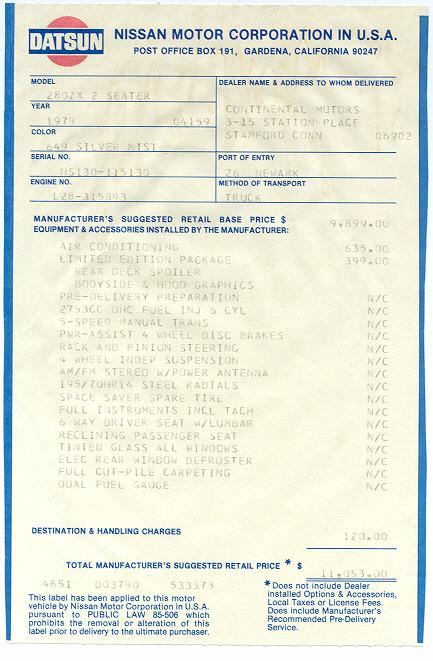
Here's a sticker someone posted in another thread for a 1979
-
Haven't ya got any real problems to solve on your Z? If curiosity is gonna kill your pu***, err, cat, then I'd get out the Factory Service Manual (FSM), see which pins those wires lead to, and trace it back. Here's a manual (pdf) for a '78, better than nothing as a starting point. http://www.xenons30.com/files/FSM/1978%20280z%20FSM.zip
-
He's lucky if he only has one. Mine has several. People always ask me, "Why didn't you shoot back!"

-
Here's the last 250 I read about.... http://sfluxe.com/2012/10/07/rare-ferrari-250-gto-catches-fire-on-street-in-puerto-banus/
-
But with no diagnostic codes (OBD) or check engine light, where's the BENEFIT to the ECU being able to monitor the CSV? In contrast, at WOT, above XXXX rpm's, snapping on the CSV for additional enrichment might produce performance gains! It's hard to get injectors with enough RANGE --- small enough pulses @ idle, enough flow @ WOT --- one solution is higher PSI, another might be cheating --- adding CSV flow for full throttle operations! I can't wait to rig up a dash light to show me if this is what the ECM is doing!
-
Here's a thread I started with a link to a website http://www.lucubration.com/pdf-tile-printer http://www.classiczcars.com/forums/thread47345.html THAT WILL PRINT LARGE PDF FILES "TILED" ACROSS MULTIPLE PIECES OF PAPER It watermarks every page, but, hey, the price is right. Free.
-
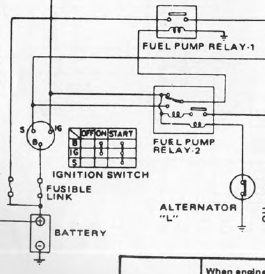
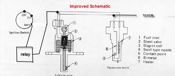
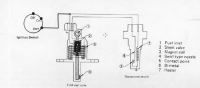
Went out first thing this morning meter and test leads in hand, to see if I could understand why my 1980 ZX is hard to start on cold mornings. Gonna start with the Cold Start valve and Thermotime switch. First thing I did was pull the connector off and zap the Cold Start Valve (hereafter: CSV) with 12V. Nice healthy click. No dropping resistor needed, you won't fry your CSV by applying B+ (battery positive) Next was to put a meter on the Thermotime (Tt) leads. Since they're in parallel with the CSV leads, should be simple, right. Just use the contacts in the CSV connector instead of wrestling the Tt connector off. (that's a trick question....don't fall for it!) Well sure enough, one of the leads shows 60 ohms, CLOSE ENOUGH to the spec for the little heater inside the Tt switch. Hurrah! The heating element isn't burned out! The other shows continuity to ground. (1-2 ohms or less). As expected, COLD. So next I apply 12V to the lead showing 60 ohms, same as it sees when you crank the car. The other lead should go from continuity to ground to open circuit (OC) once it warms up, right? Ten second, thirty seconds, it never opens up. Remains grounded. So the little relay contacts are welded shut, right? Wrong. Who's got a guess as to what's going on? Anyone??? going on.... When I unplug the Tt leads (bullet connectors) on top of the motor and test the Tt ALONE, in ISOLATION, it operates exactly as expected. After 5-10 seconds continuity goes away, which would turn OFF the cold start valve, exactly like you'd want it to. Let it cool down a minute and continuity returns. Conclusion: Tt switch is working. So what's going on? Bad wiring shorted to ground, so the CSV is ALWAYS seeing a ground, even after the Tt has warmed up? Well, that might explain why my OLD CSV failed. (I'll bet it ran very rich and got truly horrible mpg's before it did.....but let's not jump to conclusions!) So I start cutting into the wiring harness, which is baked and brittle, to see if there's a short or melted wires or anything between the Tt connector and the CSV connector. And lo and behold, it's not all as simple as you would think. Not only do the green/black leads (starter signal) from both Tt and CSV connectors meet in a splice, with a third going back to the switch or fuel pump relay or whatever.... So does the Yellow /white wire. (Wire which warmed-up Tt ungrounds to stop CSV operation) In the simplified diagram in the EFI bible, the Tt provides the CSV with ground, and that's IT! The two should meet and be done. But not on the larger, EFI harness schematic. The side of the thermotime switch that gets grounded ALSO meets in a 3-way splice with one wire going back to the ECM. But why? The ECM could PERHAPS use this to ground the CSV whenever it chose to, for enrichment, say under heavy load.... or perhaps for monitoring purposes.... diagnostics... Are you with me on this? If the Tt valve heats up, and ungrounds the CSV so it can't spray anymore, the ECM could, at it's choosing, CONTINUE to ground it / command the CSV to spray. Apparently with Key off, Engine off, (KOEO) the ECM provides a ground to this signal, which is what I was seeing on the meter. Turning key on, same thing. (At least, since I'm not cranking, the CSV isn't spraying). Apparently the ECM could use the CSV to enrichen the mixture under heavy load or acceleration if it so chose / if the programmers designed it to. I may add a light on the dash to TELL me when the CSV is being commanded, to figure out if the ECM is, in fact, commanding additional spray at times other than cold start. As usual, what I thought would be ten minutes of diagnostics turns into an hour, plus another .5 writing it up for other Z-owners. If anyone has any insight into the CSV signal going back to the ECM, now's the time to share! Otherwise, I hope this keeps YOU from misdiagnosing your Tt switch as bad. Here's a "more correct" diagram.....Not gonna post the full EFI schematic...

-
FWIW, despite numerous attempts at adjustment, I could get my AAV to close all the way, but NEVER to open all the way. It provides a maximum of 150 rpm difference open vs shut, cold vs hot. Which is perhaps part of my cold starting problem now that cold weather has arrived.
-
Oh yeah, but I assume others doing research (like I was) will benefit from corrections to the archive. And the 60-100 ohms is just the resistance of the heater coil, so it looks like the CSV operates on full B+, a question I asked in my private message to you. Lastly, for anyone actually DOING research and encountering this thread, the CSV should, per the EFI "bible" spray for a maximum of 9-12 second.