djwarner
-
Posts
718 -
Joined
-
Last visited
-
Days Won
8
Content Type
Profiles
Knowledge Base
Zcar Wiki
Forums
Gallery
Events
Downloads
Store
Blogs
Collections
Classifieds
Everything posted by djwarner
-
Are you talking about the distributor points? Are you working on a dual points distributor used on automatic transmission equipped cars? Are you working on a genuine Nissan Distributor, many have been replaced with electronic distributor/ignition units over the years? Could you site the page number or artical you are trying to follow?
-
I had a go at calibrating the water temperature gauge this evening. Requisitioned my wife's range and set up shop with a 12Volt power supply digital multimeter with thermistor probe as well a contactless thermometer and jumpers. Before begininng I measured the sensor at 200 ohms at room temperature and dropping as the temperature rose. Recorded 150 ohms at 150 degrees. While I was getting the sensor out, I replaced the 160 degree thermostat I recently bought with the 180 degree unit the PO had installed. I had previously confirmed that it did open exactly at 180 degrees confirming the 30 degree error to be in the sensor gauge circuit. When calibrating the gauge, I at first had a difficult time trying to get much of any adjustment with the two slots in the back of the gauge. After no small amount of frustration, I discovered that the two levered adjustment joints were frozen after 41 years. The only movement was slippage around the mounting rivets! I hit the slip joints with a very small hit of WD40 and finally got the joints loose. The adjustments worked this way: The adjustment slot closer to the gauge center adjusted the the needle left and right - this is equivalent to setting the zero offset. The adjustment closer to the outer edge of the gauge adjusted the distance between the needle pivot point and the pin coming from the bimetallic strip. This adjusted the meter's sensitivity. When the pin was moved farther from the pivot point, the meter's sensitivity was decreased. When the pin was moved closer to the pivot point, sensitivity increased. There is some interaction between the two adjustments. For anyone trying to do a calibration, I would suggest first moving the pin to the middle of the adjustment slot in the needle. You will need to take the lens cover off to observe this. Supply a temperature/pressure that would be easily recognized. I assumed the center tick mark on the temperature gauge to be 180 degrees, because it is slightly offset from the center. My oil pressure gauge ranges from 0 to 140 PSIG with a tick mark in the center that I assume is 70 PSIG. With the test temperature/pressure set to the tick mark value as measured by another meter, use the adjustment closer to the center move the needle to match the tick mark. Then reset the test temperature/pressure to that indicated be the leftmost tick mark (120 degrees or 0 PSIG on my gauge). Note the error and adjust out half of the error using the adjustment closer to the center. Return the test temperature/pressure to the middle tick mark value. Use the adjustment closer to the edge to again match the needle with the center tick mark. Again take out half the error as before. Repeat these last two until the gauge hits both tick marks with the need for adjustments. Normally, calibrating a gauge would be done using the far left and far right tick marks but above procedure will verify the accuracy at the normal operating conditions which should be near the center tick marks. Some others have indicated their oil pressure gauges only go up to 90 PSIG, since this should be attainable with compressed air, using the right most tick mark would be desirable.
-
There are three vent lines coming from the tank to the vapor recovery tank. Two in the rear and one in the front of the tank. If you remove the rear trim panel and right rear trim panel in the hatch area, you can trace them to the recovery tank as well as get a good view of the filler tube. Sorry, can't help you on removing the filler tube.i
-
Looking at the inside of the gauge, there is a voltage regulator made out of a coil wrapped around a bimetal strip with the other end of the strip providing a contact point for power to the gauges themselves. According to the Haynes repair manual: "In the event of the oil pressure gauge and water temperature gauge becoming inoperative at the same time, then the instrument voltage regulator should be suspected."
-
 The dash is out of my Series I to repair cracks and to install a VintageAir AC. Pulling out the old gauges, I noticed there are adjustment screws opennings on the back of the gauge. My water temp is off by about 30 degrees high and I suspect the oil gauge is reading low. Considering the gauge is 42 years old, I can understand a need to re-calibrate. Does anyone have a procedure that can be done while I got the dash apart? Which adjustment screws do what? I have a 12 volt power supply, regulated air pressure to exercise the pressure sender and hot water to perform the calibration. BTW I've found a way to maintain the fresh air/recirculation control by modifying the blower fan in the VintageAir unit.
 -
The white with black stripe is positive.
-
Black Dragon lists a 260Z heater core on page 28 of their online catalog for $100.
-
The unit you selected does not have a compressor, condensor, drier, safety switch, hoses or fitting. If all you want is to replace your evaporator, VintageAir can sell you one for a comparable price. I just bought a VintageAir system and will be installing it next week. The VintageAir systems are designed to recirculate air from the interior only - no fresh air input. I'm going to try to save the fresh air vent by replacing the evaporator lefthand fan with a righthand fan so the opening will face the vent box.
-
I don't know if there are any significant differences with the 260z, but the 1971 Supplemental Manual has a nice section on how to remove and replace the heater and core that would probably be worth a look. At least for the 240z, dash removal was not required. You can get a copy of the manual at http://www.xenons30.com/reference.html
-
I saw Carl Beck at a Cars and Coffee meet this morning. I mentioned that I thought my Z was running around 220 if the gauge is correct. He said the preferred temperature is in the 180-190 range. I knew the current unit was replaced by the previous owner and thought he could has slipped in the wrong unit. So after reading this thread and listening to Carl, I found a 160 degree thermostat at the local NAPA and dropped it in. I based my estimate on the 120-250 range on the dial and estimated the centered tick mark was at 180, leaving 70 degrees to the right of the tick. Well, the new thermostat allowed it to climb about 2 needle widths past the tick mark, estimating 190 degrees on the same basis. I thought I had resolved the issue until I went home and heated the old thermostat on the stove. With my non-contacting thermometer, it cracked open at exactly 180 degrees. I repeated the test just to make sure. Like you, I'm going to leave the 160 degree unit installed. It was the standard for many older engines. Just goes to show you that modern manufacturing tolerances beat 41 year old temperature probes and gauges. One point though, you can run an engine too cool for reasons other than viscosity. Any non-operating car exposed to temperatures near the dew point will actually cause condensation to form in and on the engine. This is because the metal is subject to radiational cooling as well as conduction cooling through the air. Water will desolve into oil up to about 1% by volume and it will affect the lubricity of the oil. The oil has to be heated up to about 180-185 degrees to drive off the dissolved water. But this is oil temperature - not coolant temperature. So even at 160 degrees coolant, the oil temperature should still reach the 180 degree level. What amazes me is that the thermostat actually throttles the coolant temperature. This explains why I've never heard the fan kick in even in the 90 degree plus temperatures here in Florida.
-
I have a Pioneer KP-8005 Circa 1977 that came with the car when I bought it. Fewer wires than any modern receiver. Red, Black, Blue, Green and Gray. It does says Stereo on the face plate. From what I know, I would assume Red = power, Black = ground, Blue = Antenna, and Green and Gray are the Left & Right Outputs with Black as the common return. Unfortunately, the PO cut off and threw away the old harness and diked off all but 2" of the leads. I wasn't planning on re-installing it, but, like Carl, any info on the unit would be appreciated.
-
You're correct, good catch. The center console screw are M6x1.0, the heater bezel screw are M4x0.7. The complete description of the screws I removed from my Series I is Crosspoint Ovalhead countersunk M4 x 0.7 by 20mm. I lost one during a repair of my fuse panel, so I replaced them with flat countersunk socket head cap screws from the local hardware store. Mechanically, they worked fine but if you are not using the OEM radio finisher, the screws may put the panel under tension. A previous owner removed the finisher when he changed out the radio and it ended up splitting the panel in two near the fresh air vent. If you can't find the exact screws in black, you might consider using button head cap screws that come blackened and won't put tension on the panel as the countersunk screws do. Regular steel screws can be blackened with Birchwood Casey Super Blue found in any sporting goods store that handles gun supplies
-
This just showed up on Ebay. I think this is what you are looking for. http://www.ebay.com/itm/Datsun-240z-Interior-Center-Console-Screws-Set-NEW-OEM-Nissan-Hardware-/271079147874?pt=Motors_Car_Truck_Parts_Accessories&fits=Year%3A1971%7CMake%3ANissan%7CModel%3A240Z%7CSubmodel%3ABase%7CEngine+-+Liter_Display%3A2.4L&hash=item3f1d938962&vxp=mtr
-
Somebody should make this thread a sticky. I don't know a Z owner that won't face this sooner or later.
-
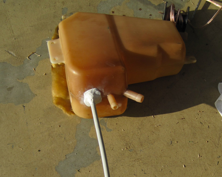
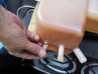
Looking at the high rez picture of the middle nipple, I have to agree there appears to be another crack in the making. Considering the yanking and pushing I did on it when re-installing the hoses, it is still strong enough to last a while. I'm pretty sure that hose was pushed up past the crack during re-installation. With the hassle of removing the quarter panel trim, I think I'll wait to repair it until the next time I'm in there or until fumes return.
-
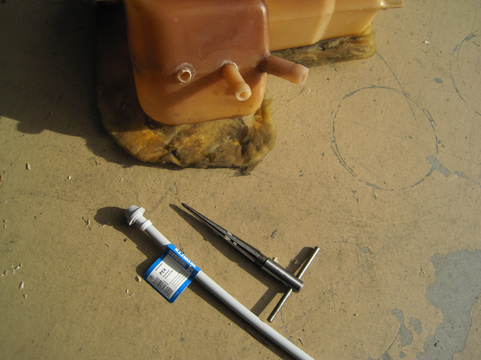
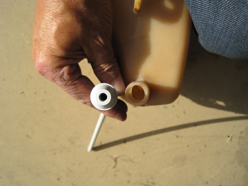
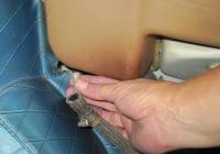
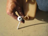
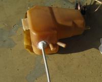
Since acquiring my series I, I have been sorting out various issues including gas fumes in the interior. After reconnecting the vapor control valve to the intake manifold, I noticed I still had the smell of fumes when I parked the car overnight with the windows closed. Yesterday I opened up the right rear interior panel to examine the vapor recovery system expecting to find rotten rubber hoses. The hoses were in surprisingly good shape, so I started examining the fitting when I found the forward tank vent hose nipple was broken off the recovery tank. Aparently someone had shortened the hose at sometime and left the nipple under tension. The through hole in the nipple was drilled off center leaving a weaken side near the tank itself. I came up with a fix since getting another recovery tank could be difficult. Went to the local home supply store and bought a PEX toilet water feed line since it had a molded head on it to secure the end inside the tank. It also was the right diameter for the particular hose. Once I got it home, I found the diameter of the head was too large to put into the largest opening in the tank, so I reduced the diameter on a bench belt sander. I opened the original hole with a taper reamer and used some speaker wire fed from the small hole to the large hole as a fish. Once the new line was inplace, I secured it with JB Weld Expoxy Putty. Doesn't look like new but it works.

-
Ok, just got back from the muffler shop. The cars a purchased had a single, glass pack muffler 3" diameter by 18" length mounted in the rear position. The drone at 40-50 mph was driving me crazy. So I had the shop install a front resonator 3" diameter by 11" length, glass packed, and a rear muffler 6" diameter by 16" in length. Exhaust was finished off with a chrome tip from the old system. I also had them install a clamped joint between the two so I could remove the exhaust to work on the rear suspension. I have no reference to judge by but the result is satisfactory to me. As was the bill at $175. Sorry, don't know what brand was used.
-
Thanks Carl, I tried to estimate the dimensions from a few pictures on this forum and from the service manual and kept coming up with a variety of different numbers. Your numbers appear to be for Z's manufactured before Aug 73 which is exactly what I needed.
-
No right turn signal did some searching and replaced both flashers.
djwarner replied to ihiryu's topic in Help Me !!
When I bought my 71 series I, the PO said the left turn signal was inop. During the test drive, all turn signals were inop but the hazard flasher and lights were working. Troubleshooting isolated down to the turn signal switch. I very carefully opened up the switch by bending back the tangs, and burnished the contacts with a woman's finger nail buffing board. All has worked properly since then. Opening the switch is not for the faint hearted, though. Very easy to screw up. There are switches available from the vendors posted on this sight, but it would be nice to troubleshoot down to the switch first. If the hazard flasher and lights are working properly, it would prove out the lamps and associated wiring. On another level, verify you actually have 12 volts going to the switch. I recently had a problem with the running lights that traced to corrosion on the back side of the fuse block that reduced voltage coming out of the fuse block. -
Ok as a new Z owner, I'm still learning things most of you learned long ago. I had tried to order OEM mufflers through a website that listed listed them as available. This morning I received a cancelation notice as the parts are NO LONGER AVAILABLE through Nissan. I had hopes since Nissan still listed the part numbers in their dealer network. That said, my 71 series I has a single rear mounted glass pack on a 2" pipe. The exhaust note is bad enough on acceleration but is also objectionable at steady speeds. A local muffler shop is willing to work with me, installing a front resonator first and then replacing the muffler if required. He asked if I had any specs/dimensions on the first muffler. So this time I'm coming to the old hands first. Does anyone have any specs on the OEM system? Diameters? Length? etc Thanks in advance.
-
Might very well be. I found the part numbers on a website and checked an online parts dealer who said the parts were available. Before ordering, I visited my local Nissan dealer who also had the part numbers with prices in his system. I am waiting for the online dealer to confirm the order and I may very well find them NLA. Here's hoping.
-
Have you thought about replacing them with OEM parts? You can get them through any Nissan Dealer.
-
Newbie needs help with 12/70 Series I 240z
djwarner replied to djwarner's topic in Suspension & Steering
Just an update. Replaced the rear shocks with KYB's and the ride height is now correct. Apparently the high pressure section of the monotube design does contribute to the spring rate. -
Newbie needs help with 12/70 Series I 240z
djwarner replied to djwarner's topic in Suspension & Steering
Went over to see Carl Beck yesterday. He was as gracious as he was knowledgable. Learned my front bumper height was good but my read suspension is 3/4" low. From our conversation, I was able to lay out a strategy for the next year or two. Thanks Carl -
Newbie needs help with 12/70 Series I 240z
djwarner replied to djwarner's topic in Suspension & Steering
Don't know the correct measurement procedure, but from the center bottom edge of the bumpers, the front is 17.625" and the rear is 16.5". BTW I'm here in New Port Richey.