inline6
 Subscriber
Everything posted by inline6
-
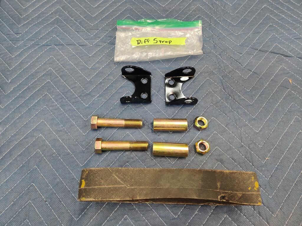
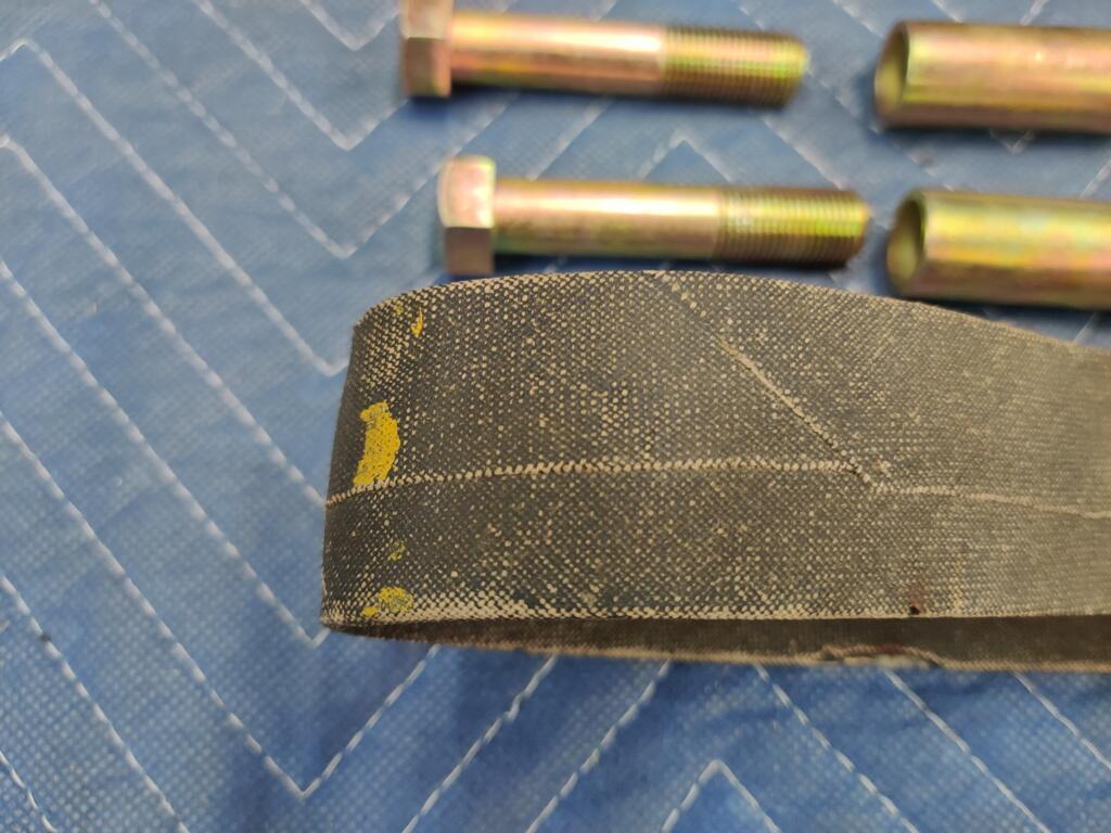
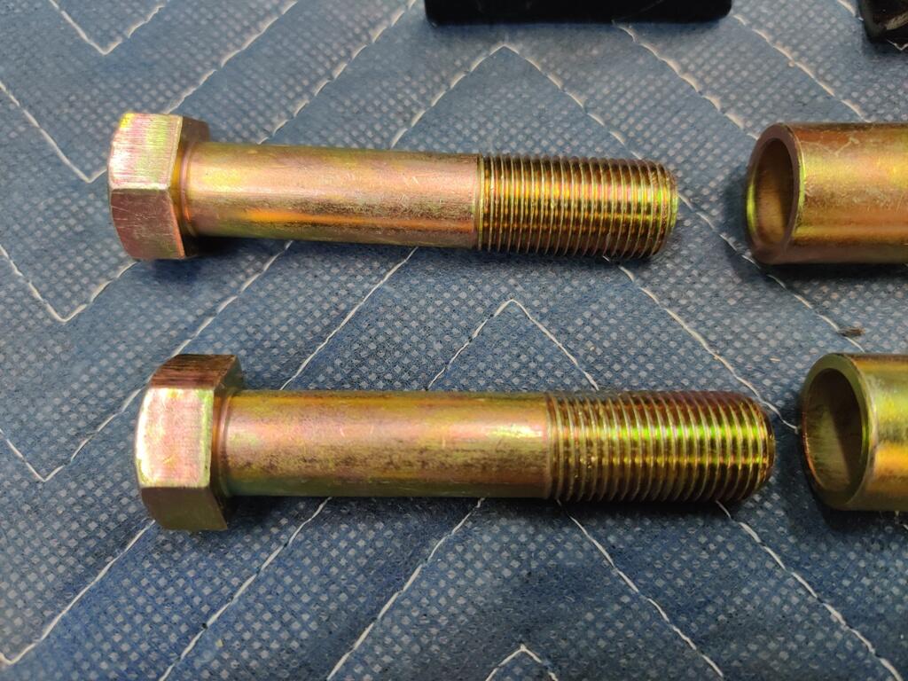
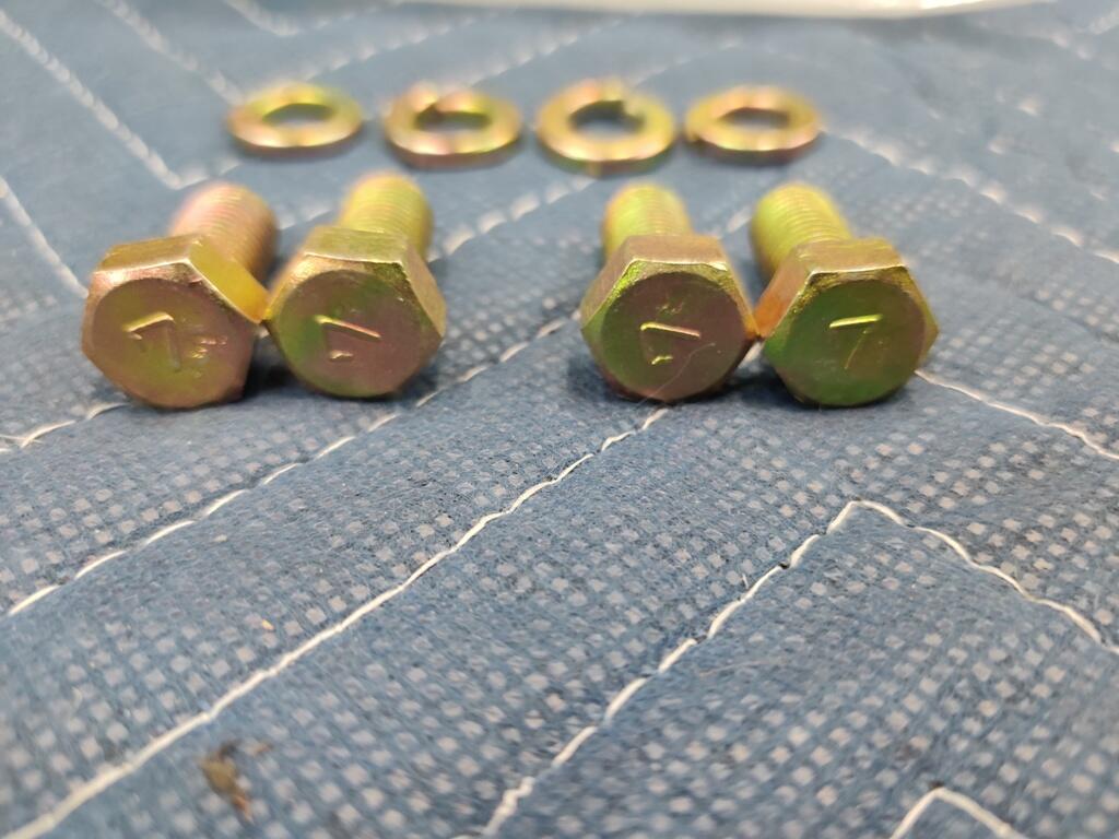
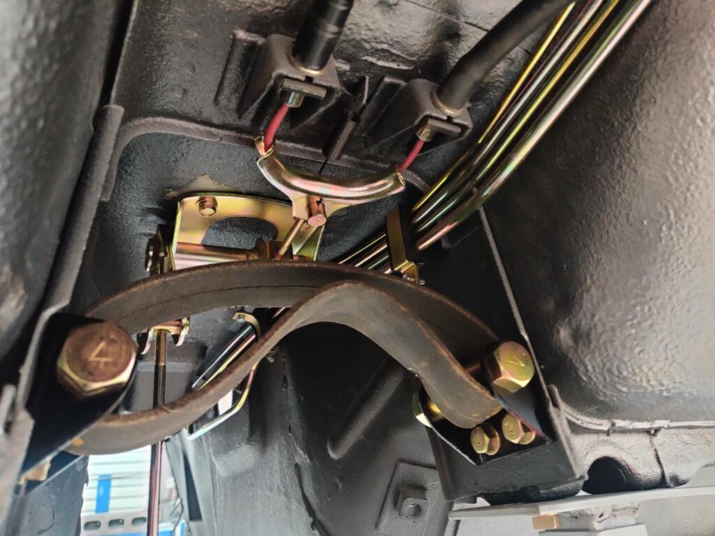
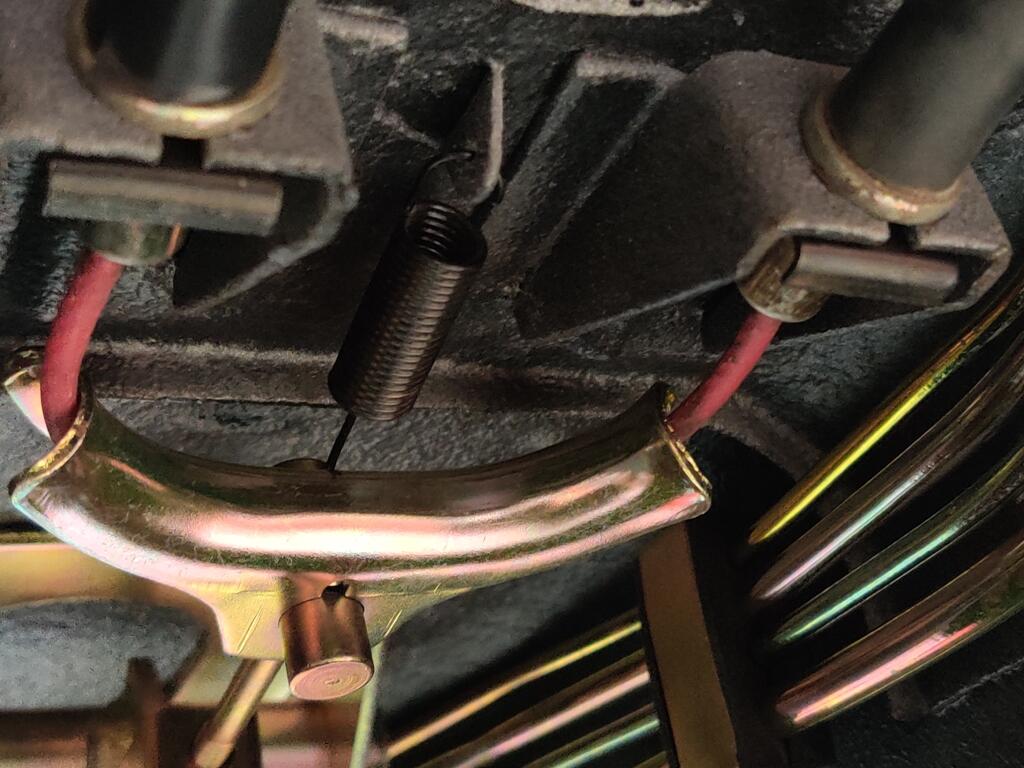
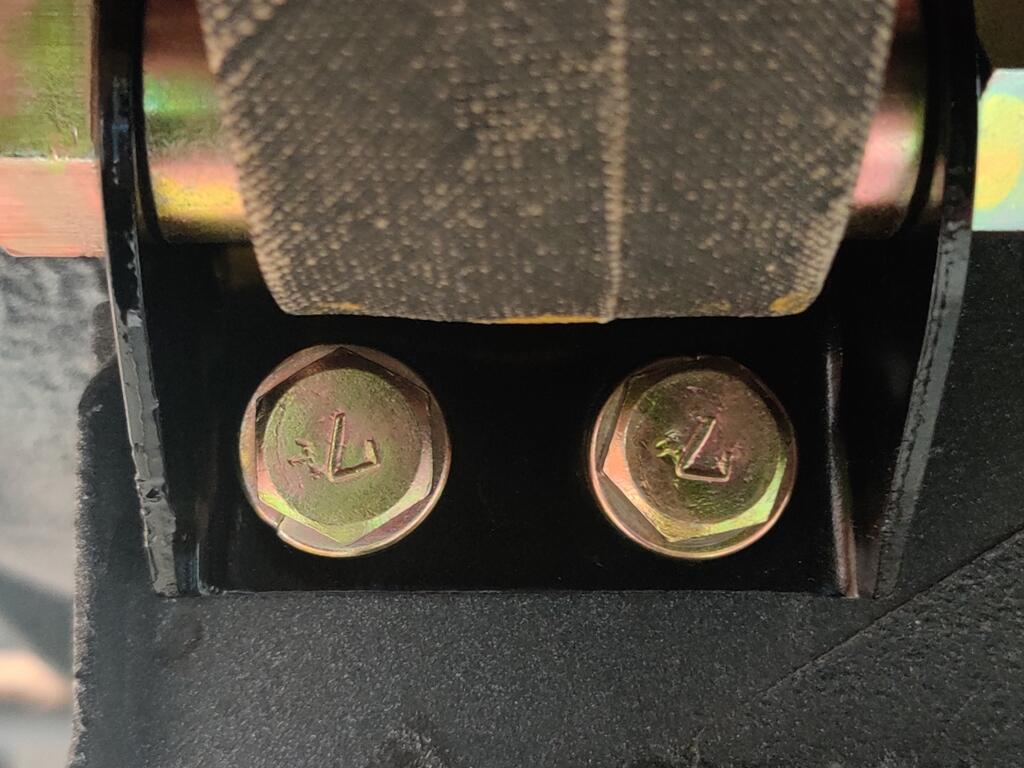
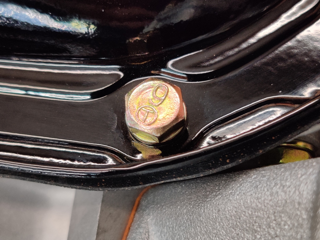
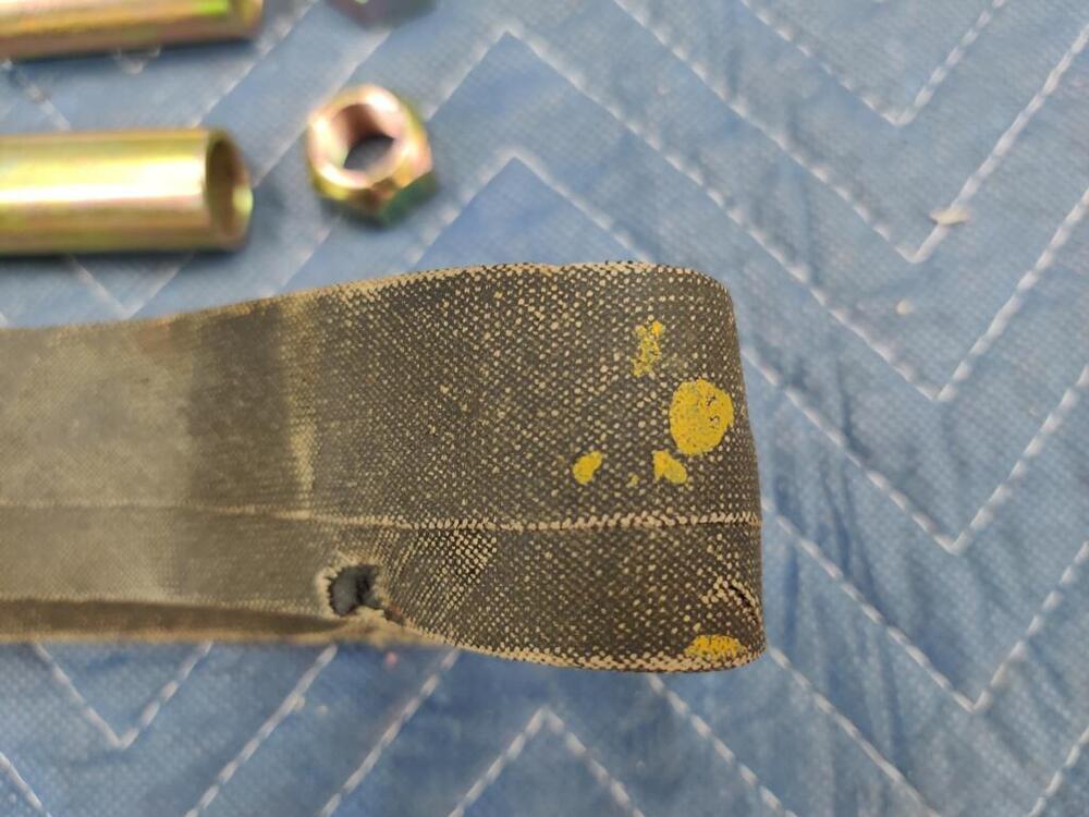
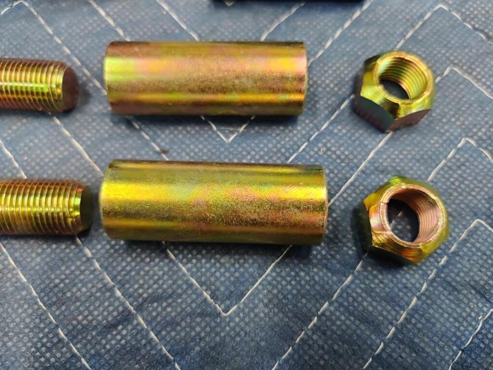
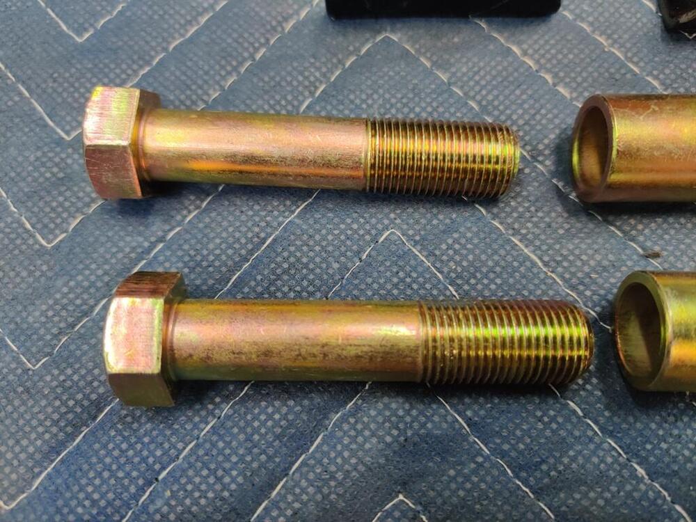
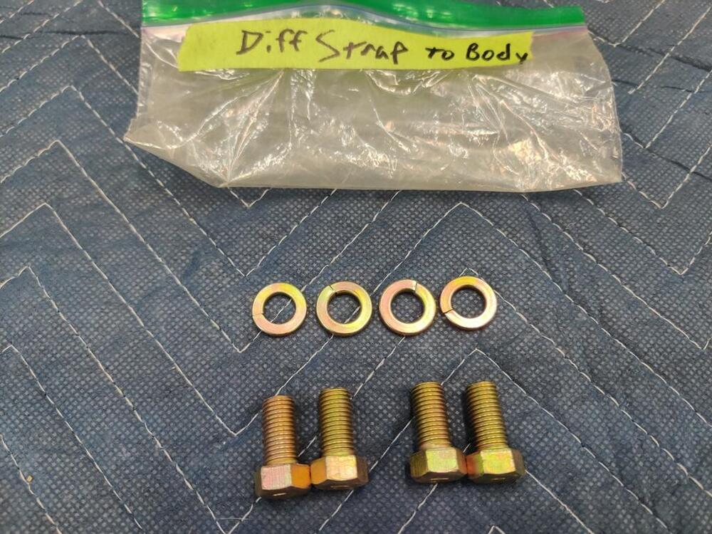
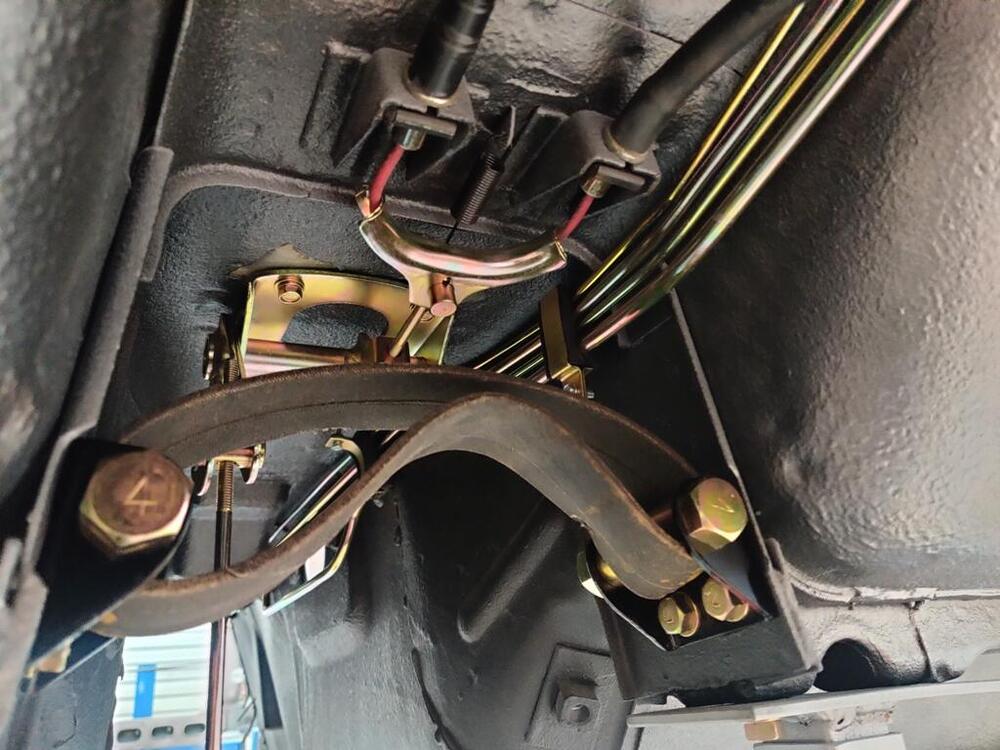
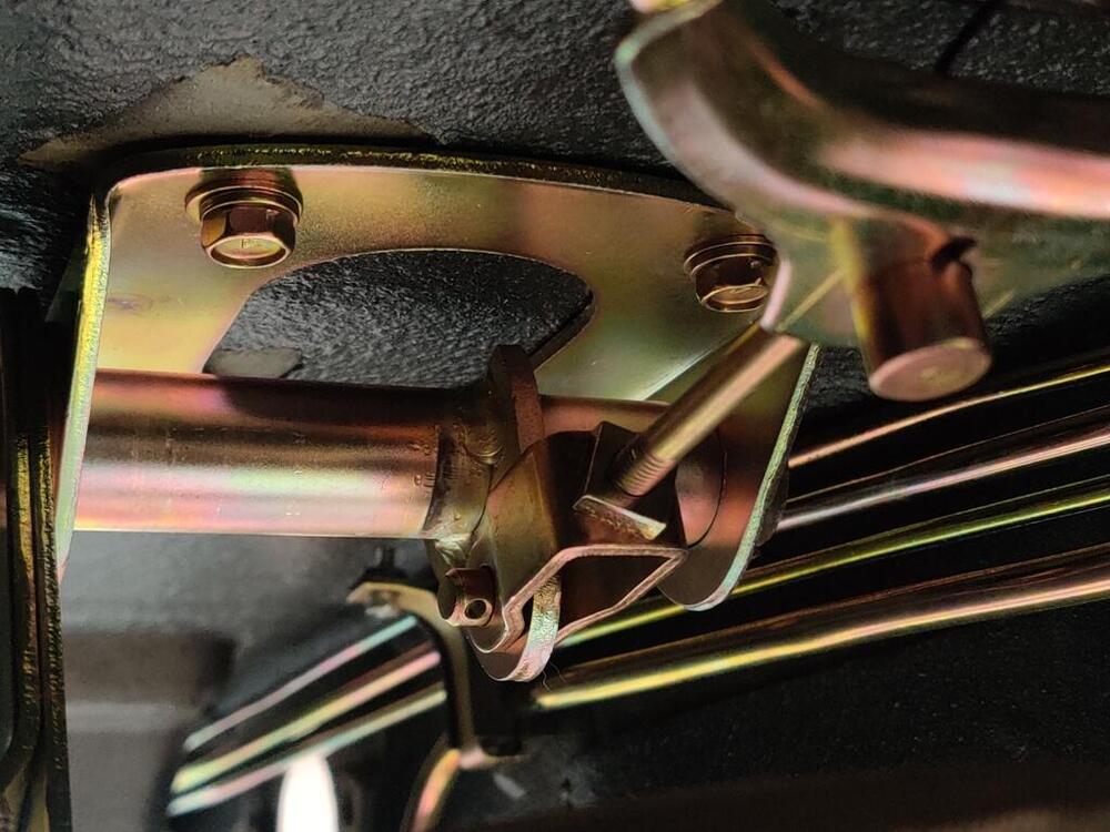
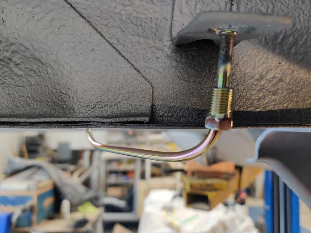
 Thanks Steve. I will check those out. Tonight, I put the differential strap in. I reused the original differential arrestor strap. It is in decent shape - it even has original yellow paint dabs on it. One of the things that really excited me about this car was that it spent all of its time prior to my ownership in AZ/CO. The restored hardware is so nice - not pitted from rusting. As these parts go back on the car, some pictures capture the resulting "art":


-
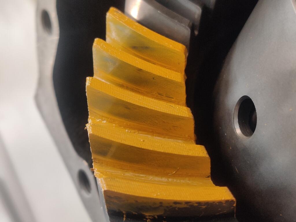
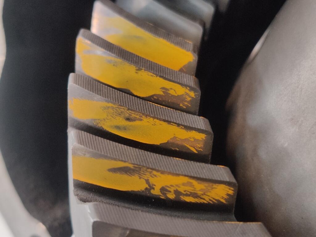
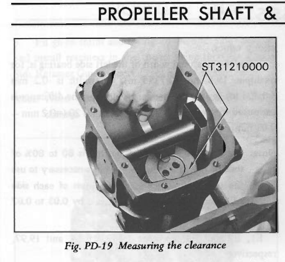
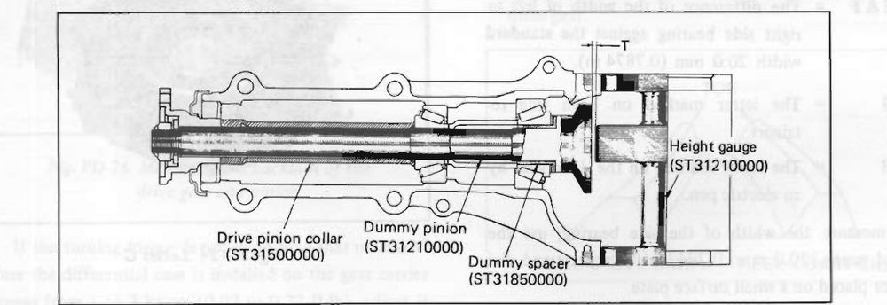
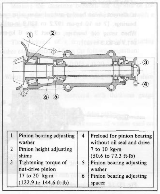
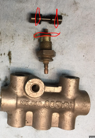
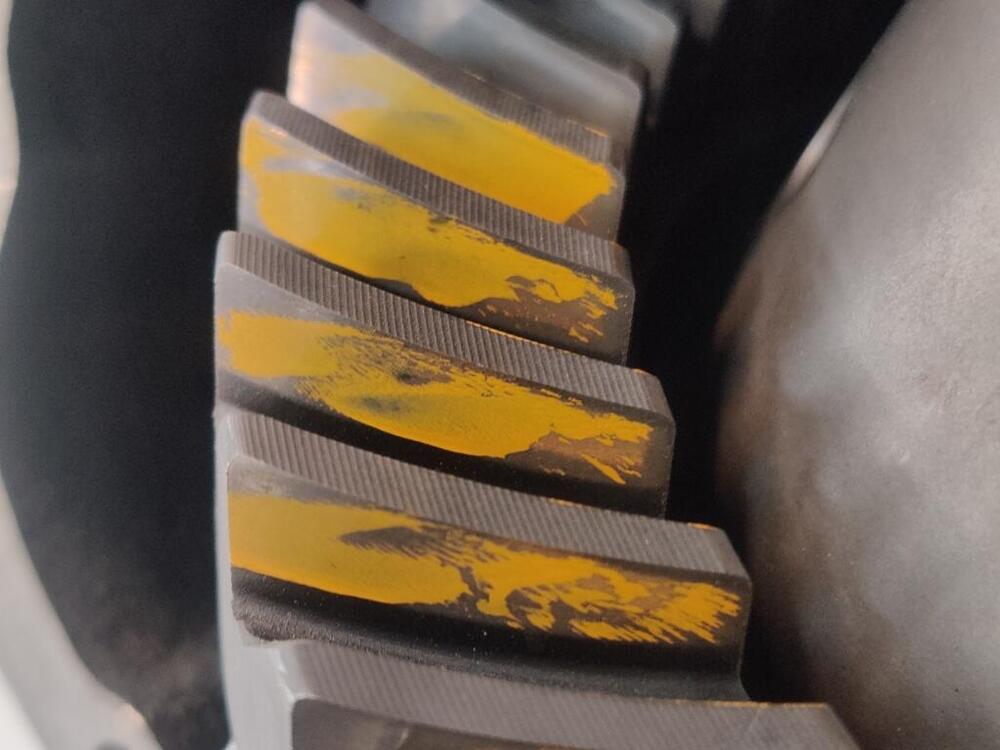
Picture 1 and 2 is using the standard method. Pictures 3 and 4 is just my idea to see if it is any more clear to see the contact areas. The pattern can be hard to see clearly. For what it is worth... here are pictures of the tools for setting pinion gear (height): There is a fake pinion shaft and a bar with square ends. The plan at this point includes removing pretty much everything and pulling the bearings off of the pinion to get to the washer that is #1 in this picture: There were no shims (#2 in the above picture) on this differential. There was only a washer. I need to measure the thickness of this and then either, add a shim (#2) of the correct thickness, or replace the washer (#1) with a thicker one. On Subaru websites, I see only spacers (#1) available: https://www.subarupartwholesale.com/a/Subaru__STI/49247923__6023356/DIFFERENTIAL-INDIVIDUAL/G11-195-03.html Nissan websites show both the spacers and shims as discontinued.
-
Nice collection. Those are the crush washers of course. The o-rings I am wondering about are inside the switch.
-
Ha! Good to know... as I reused the original aluminum crush washers too. I am less worried about those leaking now, given your experience with that. Thanks for sharing. Wonder if there is a way to determine suitable replacements for the o-rings...
-
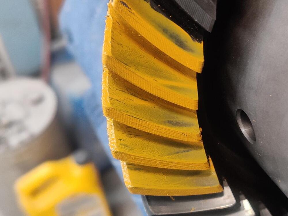
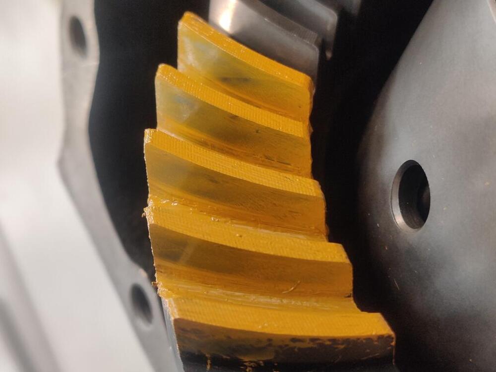
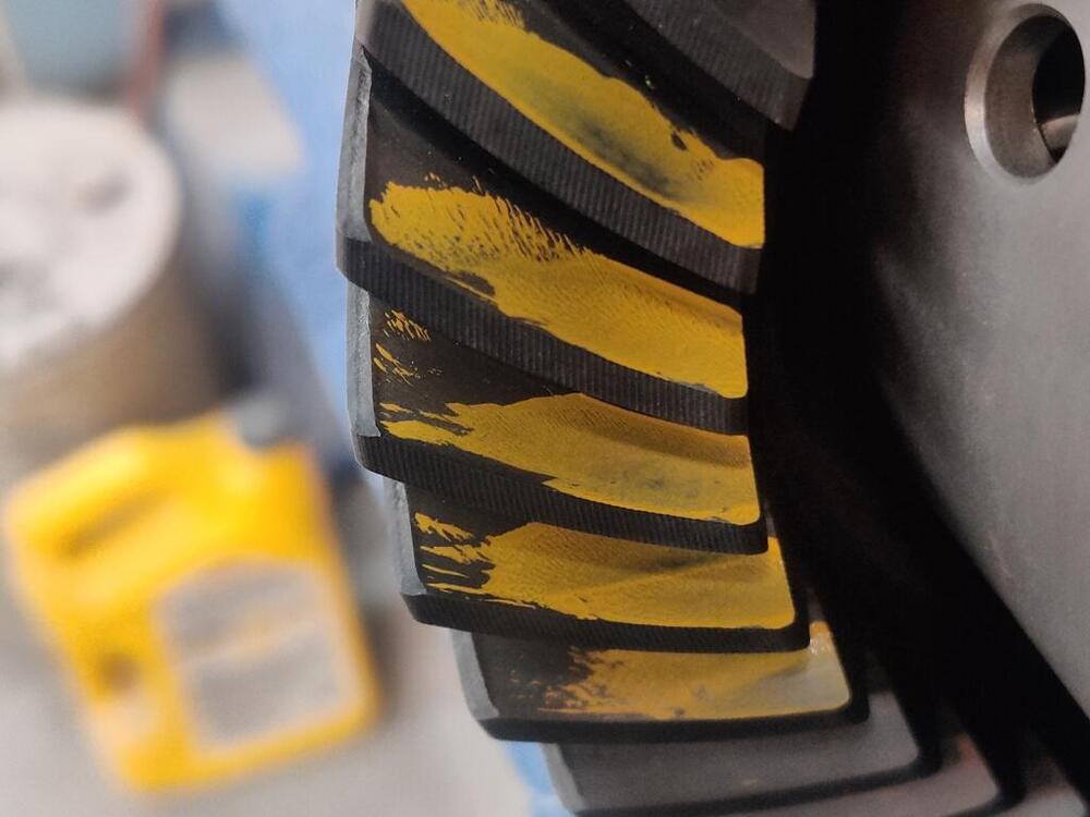
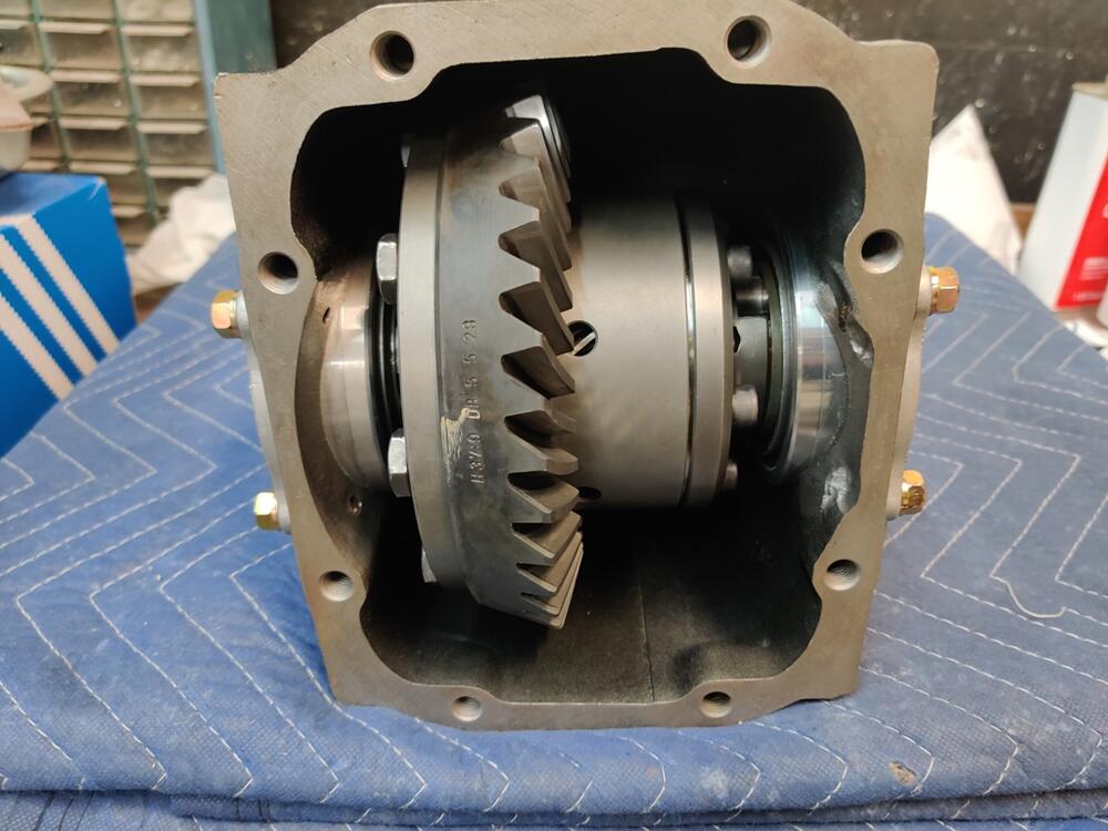
Tonight I backed the pinion nut off and reset torque to the low end of the specification. While I had done 135 ft lbs before, I did 124 point something this time, just a couple of ft-lbs above the 122.9 minimum spec. Interestingly, the inch-lbs of turning torque dropped from 14 to 10, which is much closer to the upper end of the turning torque specification. Keep in mind that I measured this with the pinion seal in place, which is not how the factory manual calls for that to be done. You are supposed to check the turning torque without the pinion seal installed in place, and then remove the nut, install the seal and torque the nut again. I think that is kind of ridiculous. So, I am willing to gamble that the 10 inch-lbs I am seeing with the seal installed is just fine. After doing that, I reinstalled the carrier and side retainers, and check the gear wipe pattern: front side of ring gear (first pic), back side of ring gear (second pic): The first pair of pics shows where I applied the yellow paint directly to the ring gear. I went back and forth through that with the pinion gear to get the first set of impressions. After that, I kept rotating the pinion gear around until the paint that transferred from the ring gear to the pinion gear made another set of marks on "clean" teeth on the ring gear. The transfer of paint from the pinion to the clean teeth on the ring gear is captured in the second pair of pics. What I see is "toe" contact on the coast side of the ring gear (first pic). And I see heel contact on the drive side of the ring gear (second pic). According to the shop manual, I will need to "increase the thickness of the drive pinion adjusting shim and washer so that the drive pinion is moved to the drive gear". As I see it currently, I'm going to have to remove the carrier from the case (which requires removing one of the ring gear bolts in order for it to clear the case), and to remove the pinion gear, and bearings so that I can add a shim of unknown thickness to shift the pinion gear towards the ring gear. If I guess wrong on the shim I install, then I won't know until I assemble everything again. If wrong, it all has to come apart again. I guess again... rinse repeat... I think I see hours of time and frustration for this little project in my future. Anyone have factory tools for me to use to get this thing set up properly without a bunch of hassle? Or ideas for how to save that time and hassle?
-
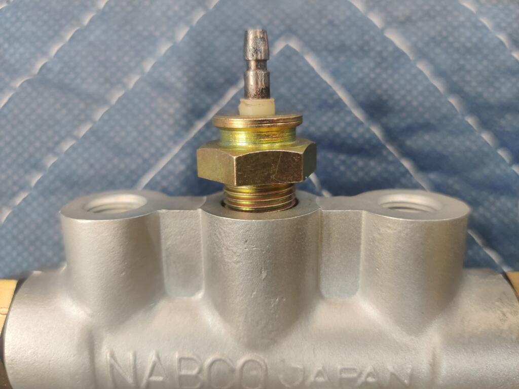
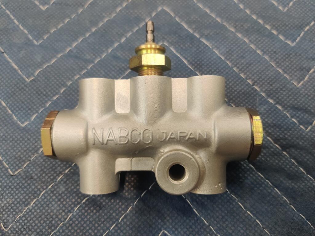
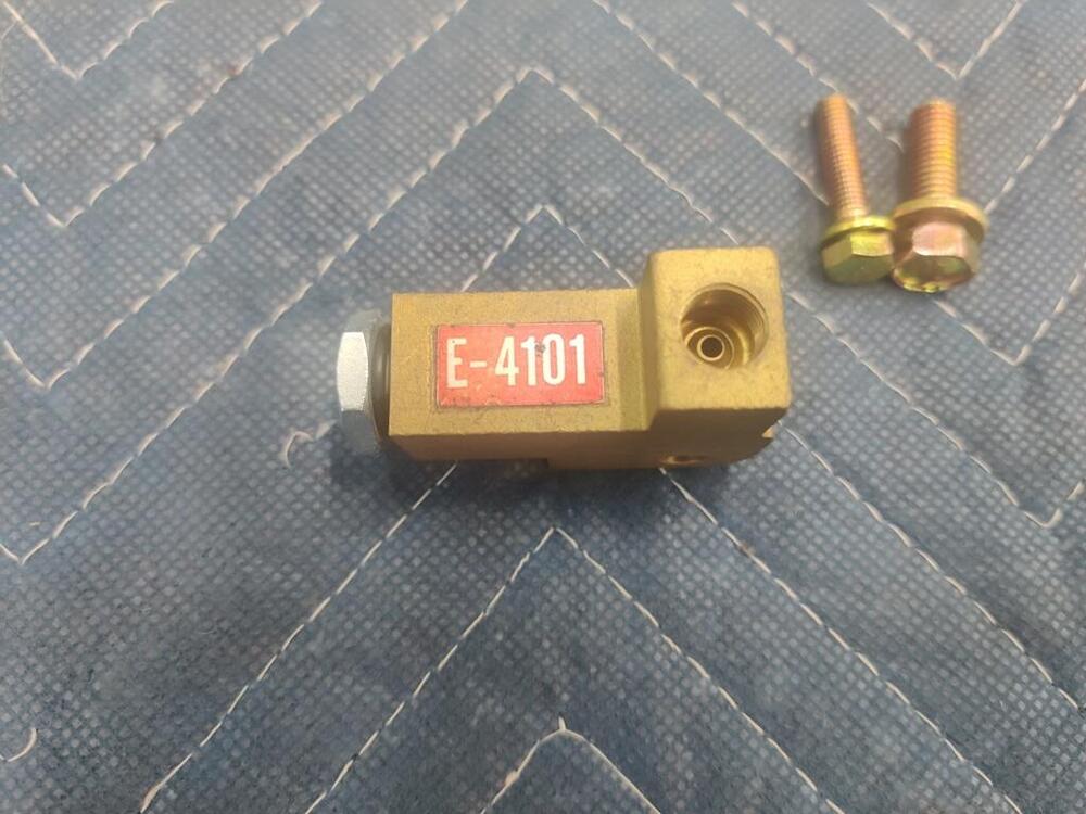
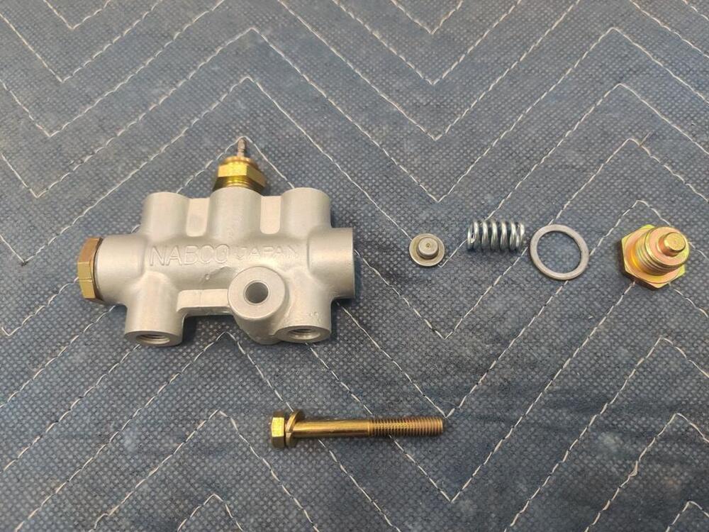
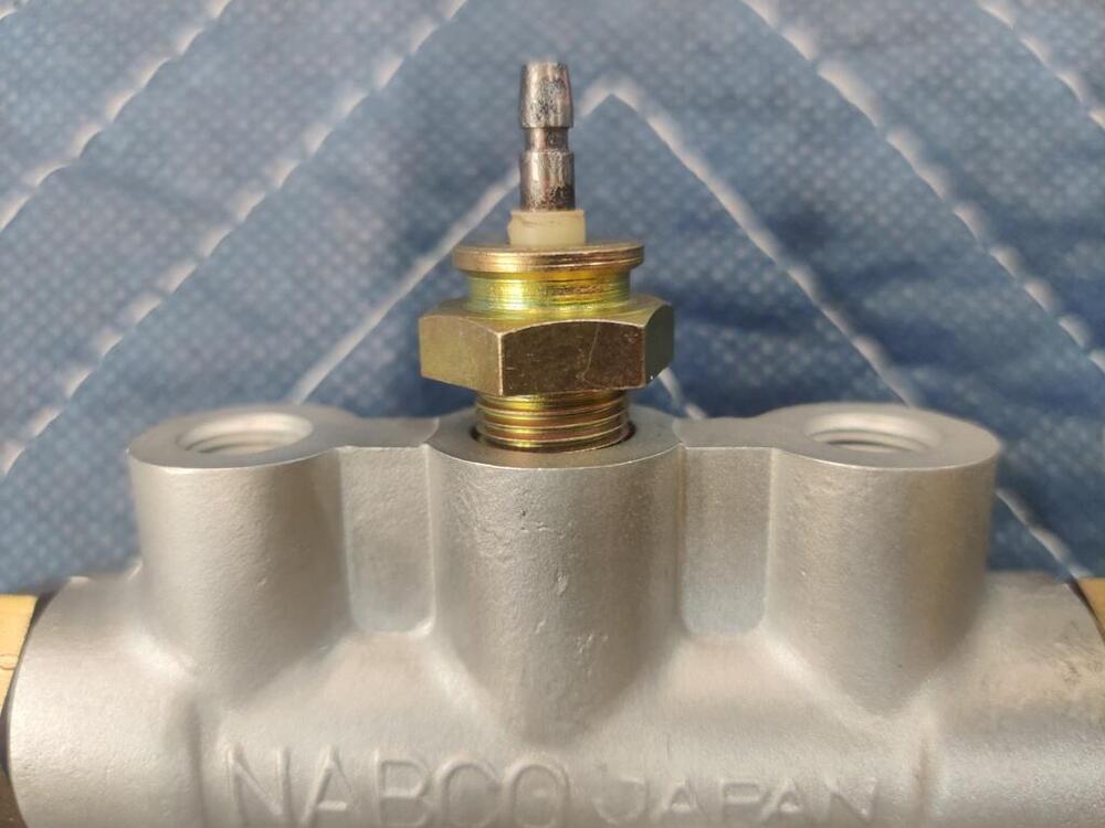
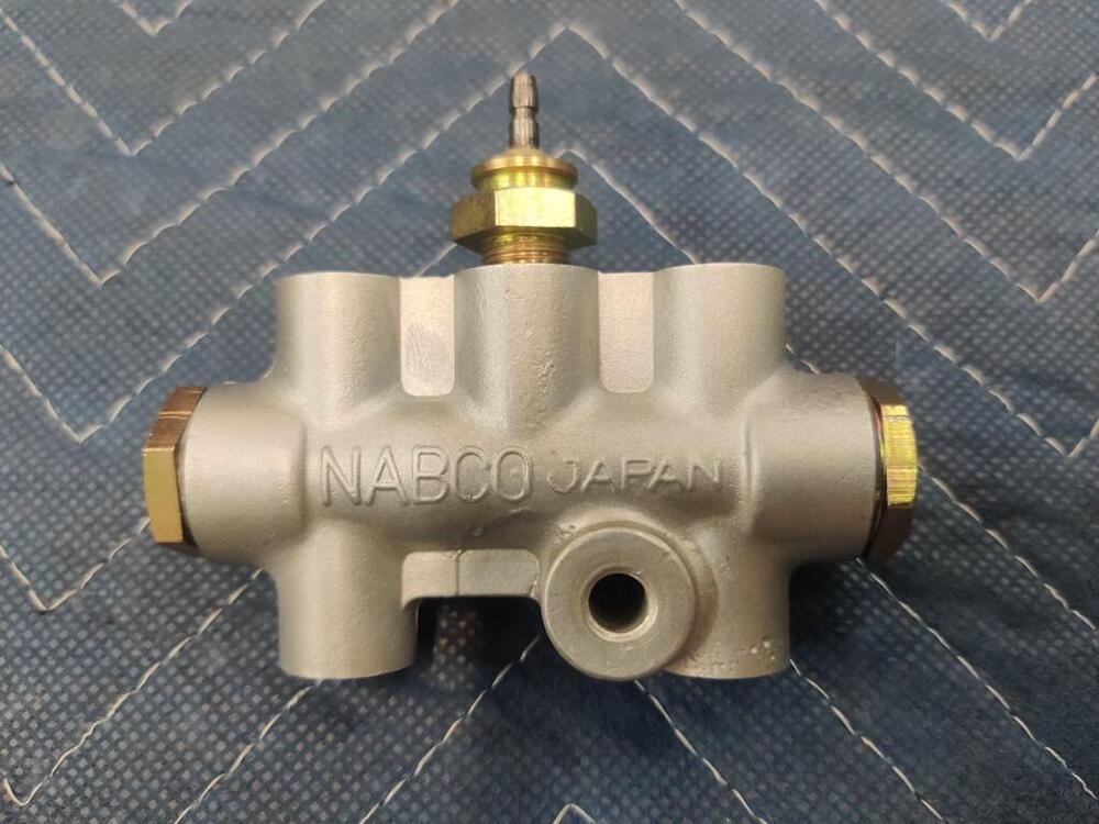
I think you are right - it is a brake light switch (not proportioning valve). That is the one that came with my car. I disassembled it, sent off a few internal and external parts to get them plated, and glass bead blasted the body. I glass beaded it at 90 psi to clean... and then another pass at about 50 psi to give it a smoother finish. Interesting. Maybe I will do the same for a measure of safety. Having brake fluid squirt all over the engine compartment and the damage that would cause... 🥶 I feel a little uneasy about reusing the original o-rings, but that is what I did. I don't know how to source suitable replacements that would meet the performance criteria?
-
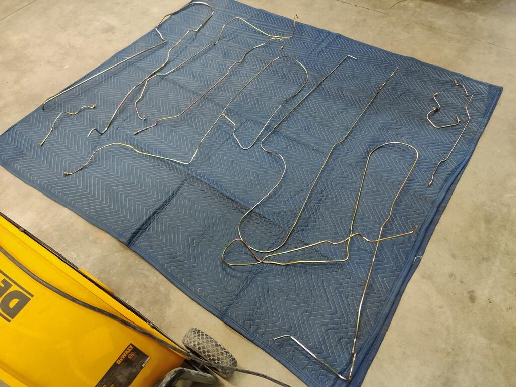
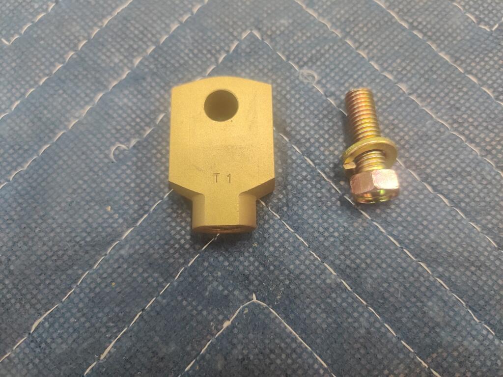
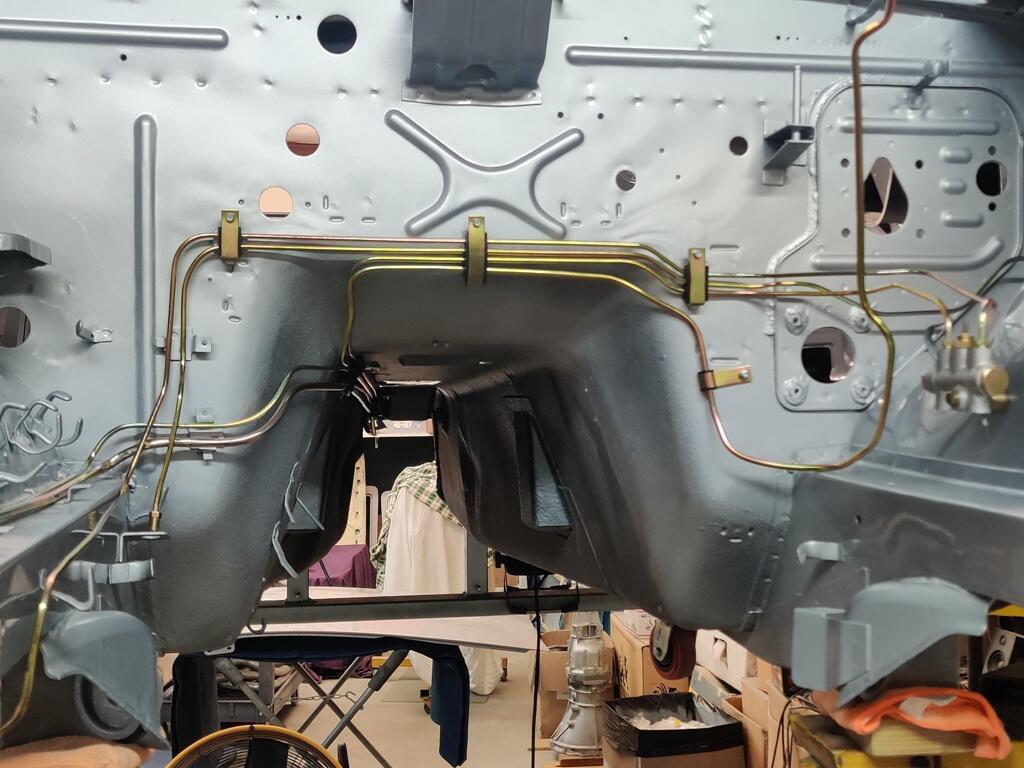
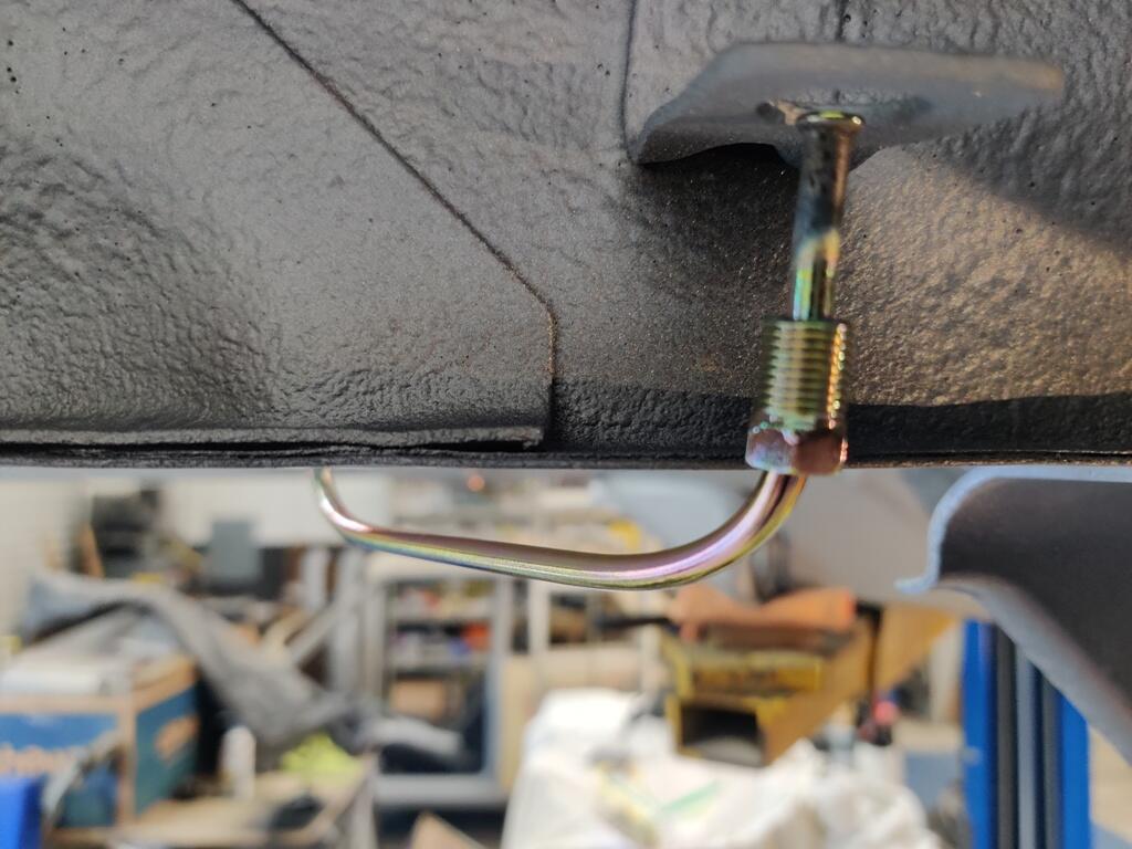
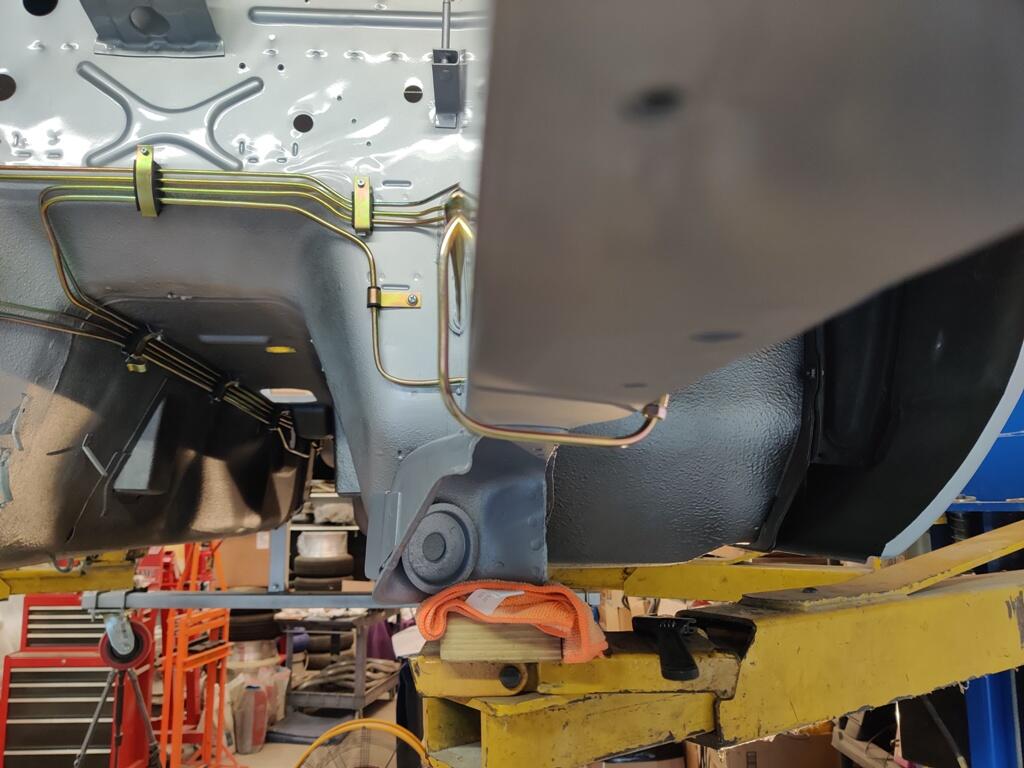
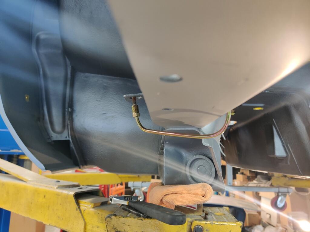
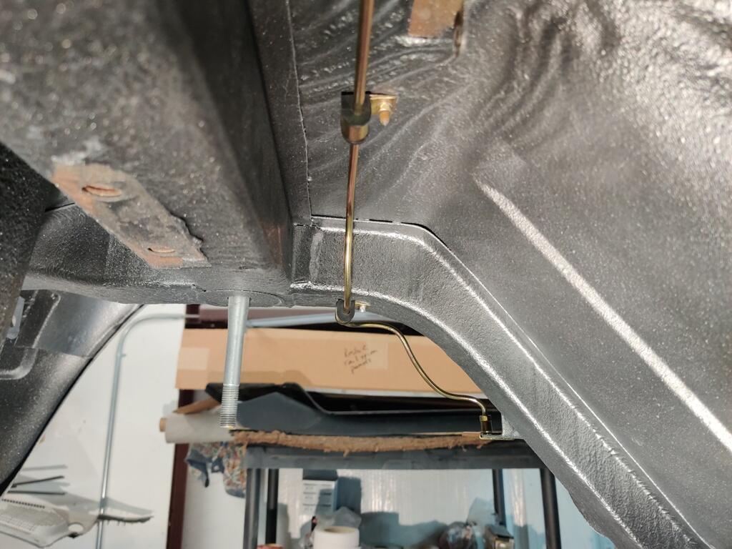
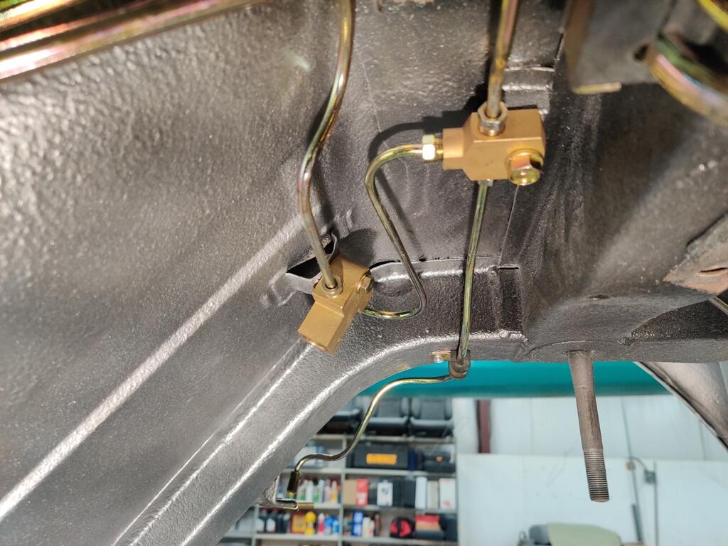
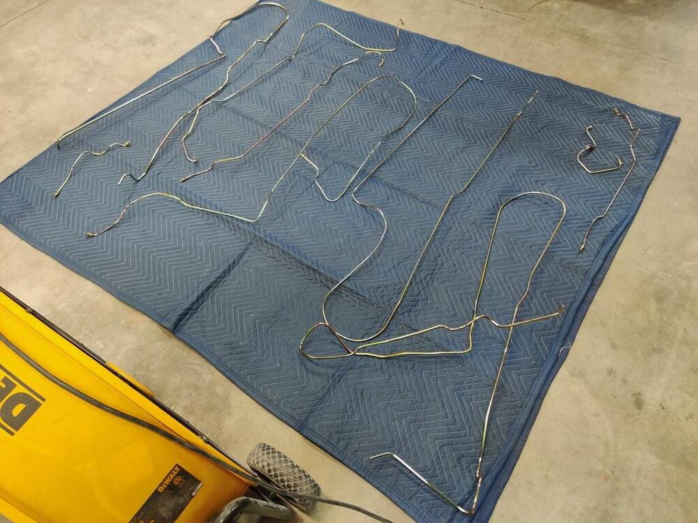
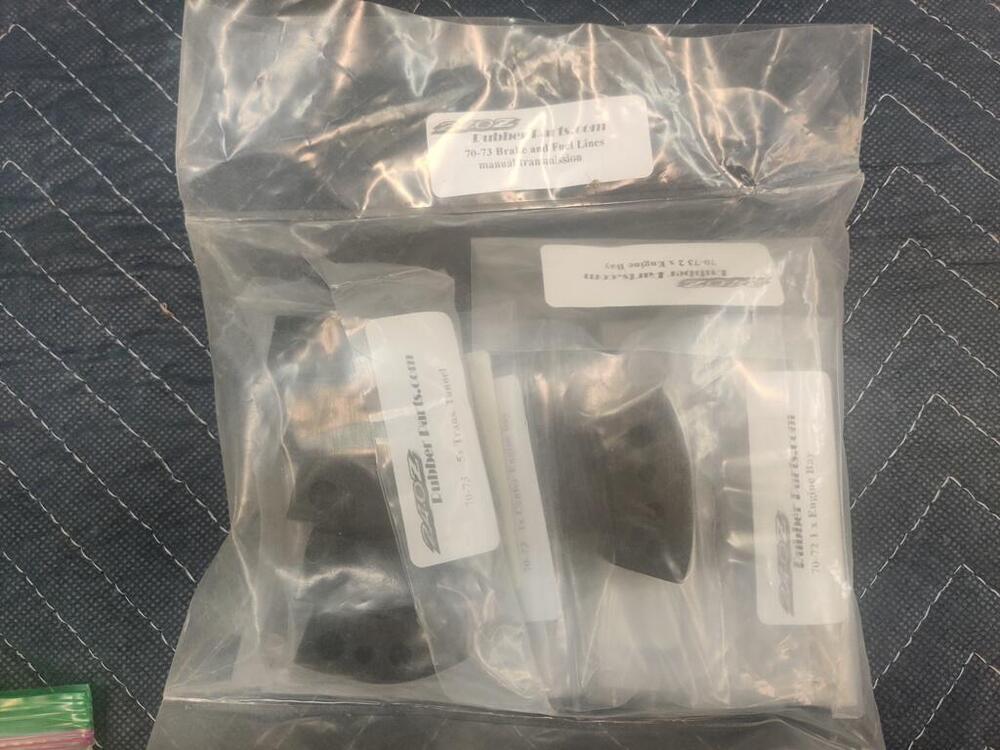
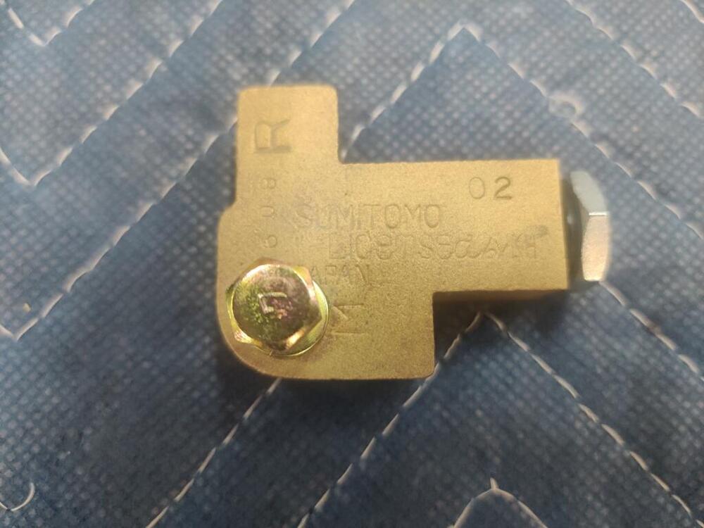
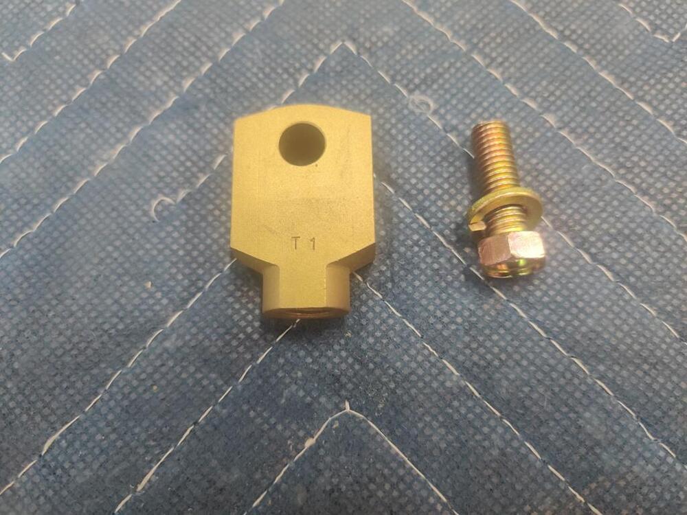
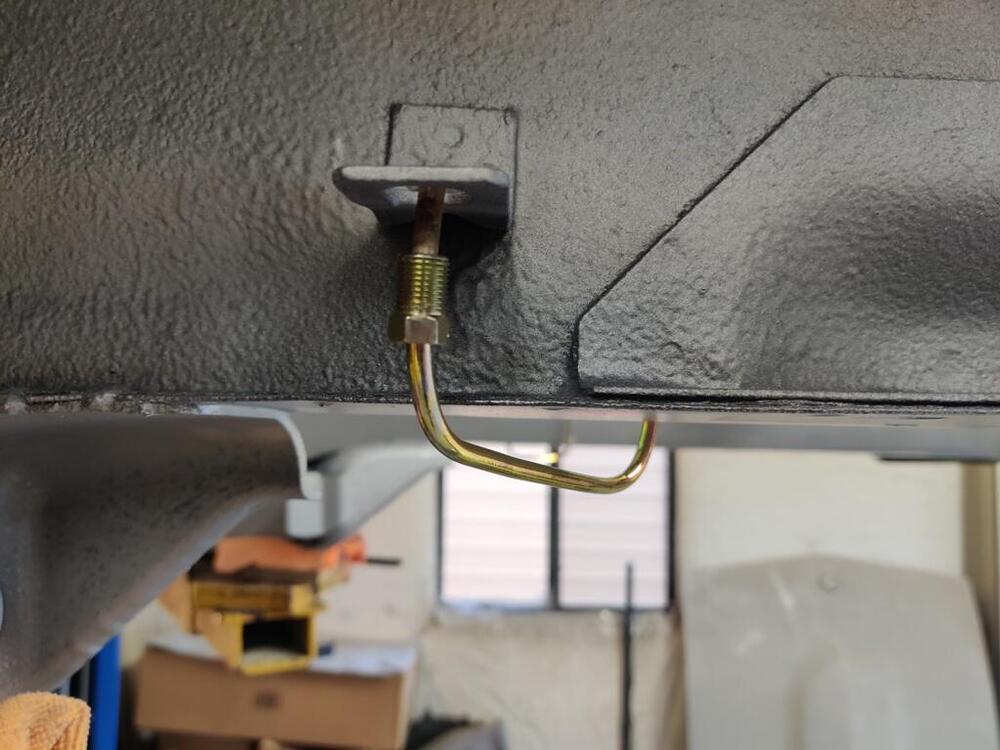
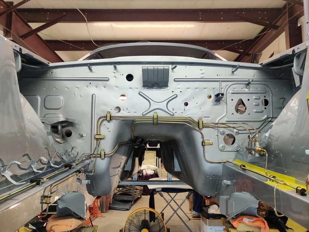
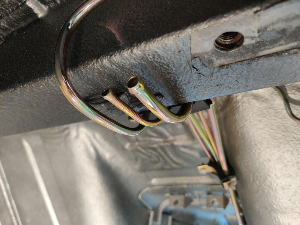
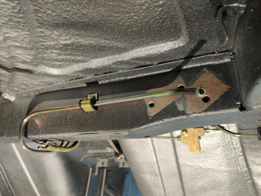
Thanks for the comments everyone. I have decided to use the new ones. I will think about how to check driveshaft alignment, and maybe I can report back what I find when I get to that part of assembly. Over the past two weekends, and for a few hours during the last week, I put my attention to the hard lines. I think it was @motorman7 that I got the tip from for bending the lines for shipping and plating. I used a welding gas cylinder as a "form" and bent the longest lines around it. The 180 degree (or so) bends in these are the result. Unfortunately, either during shipping back to me, or during the plating process, several of the lines got rather "jacked". The vapor tank vent line was especially messed up. I think I have about 10 hours in just straightening and getting the lines refitted, assembly of the brake proportioning valve, etc. I sourced all new rubber insulators for the hard lines from www.240zrubberparts.com. proportioning valve was disassembled, glass bead blasted, internal and external parts plated, etc. I am unsure if there is supposed to be a crush washer under the fitting with the electrical post. There is a rubber o-ring on the shaft of the plastic around the post, so I think that is the only thing that seals this "port". Crush washers are used with the front and rear yellow chromated fittings. As you can see, the vapor line is reaching for the sky at this point (above right). Left front brake line (first two pics) and right front brake line (third pic): Right front brake line from another angle, vapor line orientation corrected, and rear inlets of fuel lines (third pic): Beginning of vapor vent line, rear brake line, and "y block" and rear brake "delay" valve: I have several different things holding up parts of the assembly. I still have to resolve the differential carrier backlash issue. The flywheel needs to be resurfaced. I need to paint the steering rack case before I can assemble the steering rack. I have assembled a long list of reassembly items, specifically in the order I think is best. It is quite long. To share, I will put it into a Google sheet.


-
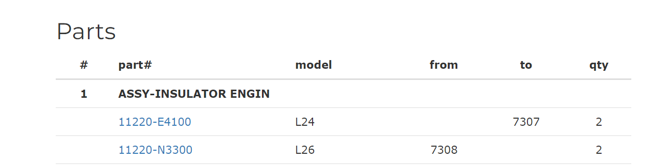
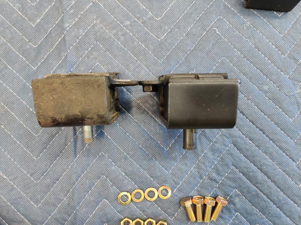
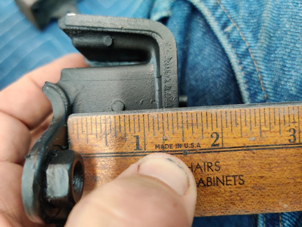
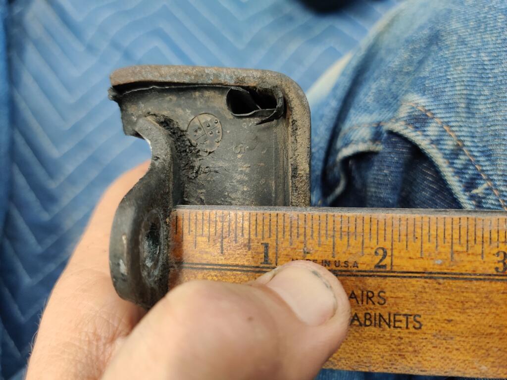
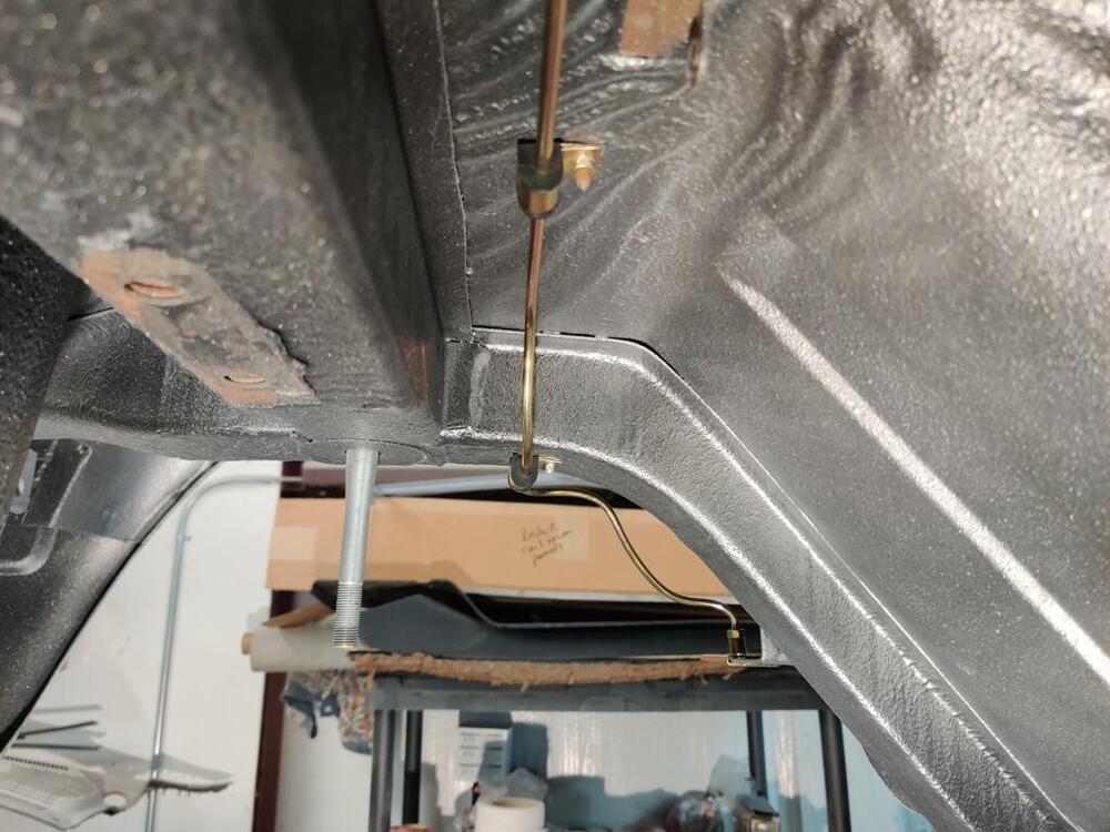
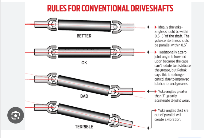
I did some searching for differences in the two OEM motor mounts: I found some discussions about aftermarket motor mounts and problems with them, but I couldn't find information from anyone who compared the two OEM variants. I have a hard time believing that the original rubber mounts have shrunk as much as the difference I measure here. It is certainly easier for me to use the new ones, as I don't have to prep the old ones. I do have one question though. When you raise or lower the engine, that in turn will change the angle of the transmission output shaft. How much will that matter? In theory, it would only change the angle of the splined front section of the driveshaft. I have seen pics where the angle of the front and rear sections of the driveshaft have to be like in the top of this picture: Worth considering?
-
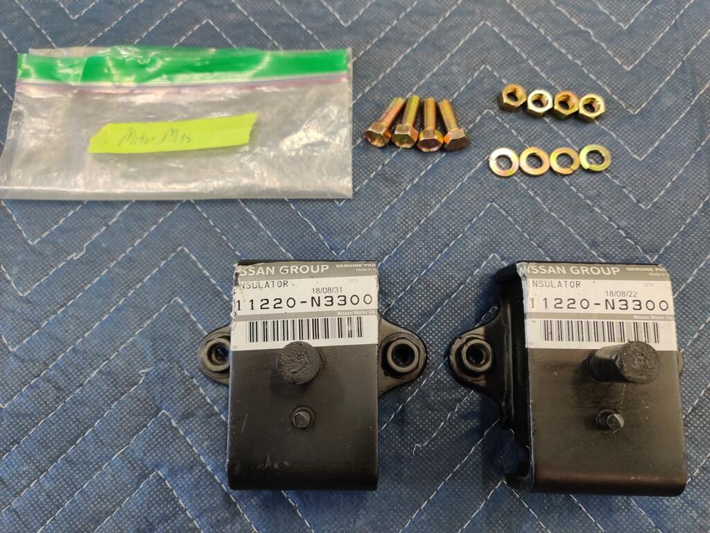
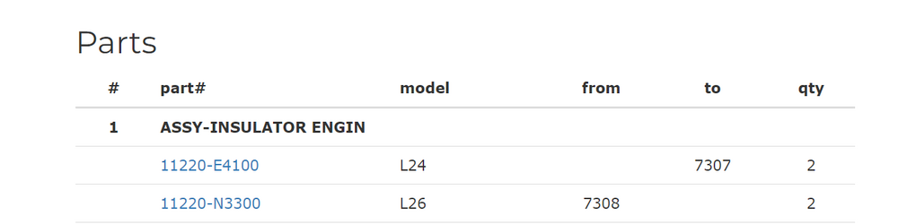
In looking at the new motor mounts I bought and comparing them to the originals, I see some differences. While I would have liked to use brand new parts here, unfortunately, they are about 1/4" taller than the original mounts. My originals appear to be in very good condition, so I will probably glass bead blast and paint them, and re-use them. New: Original:


-
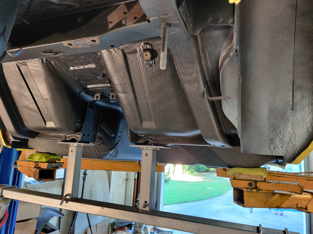
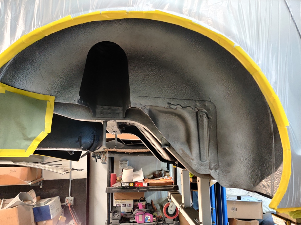
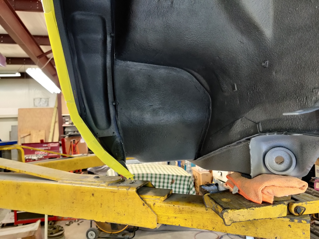
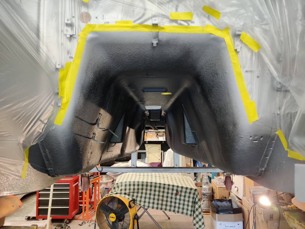
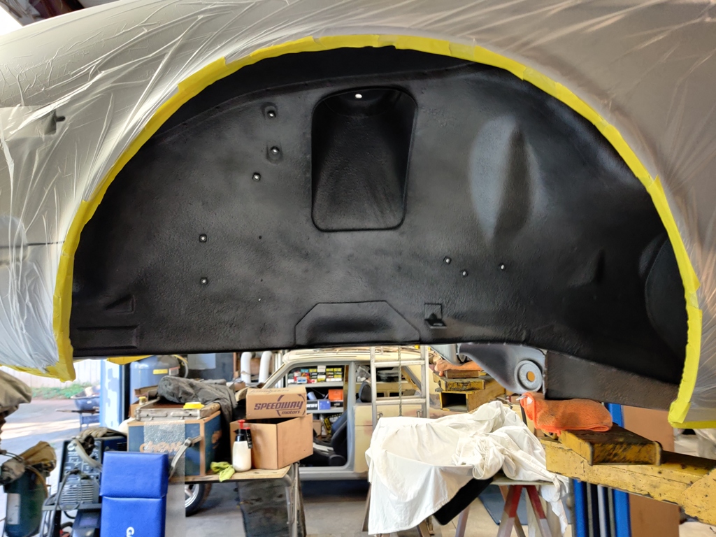
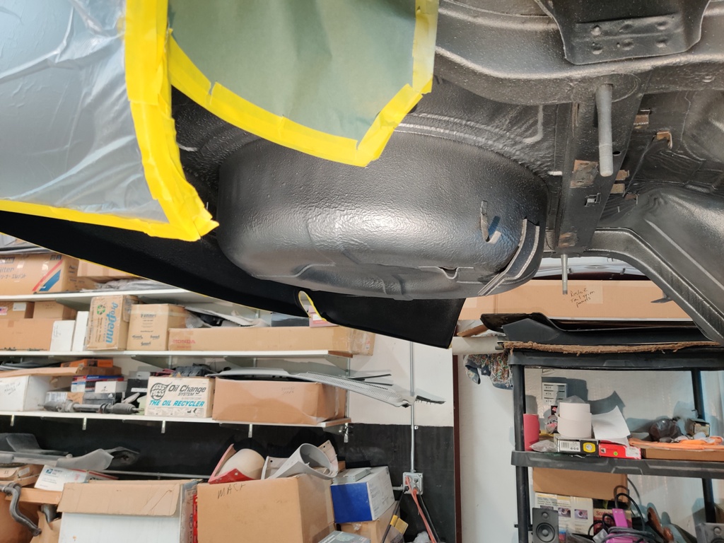
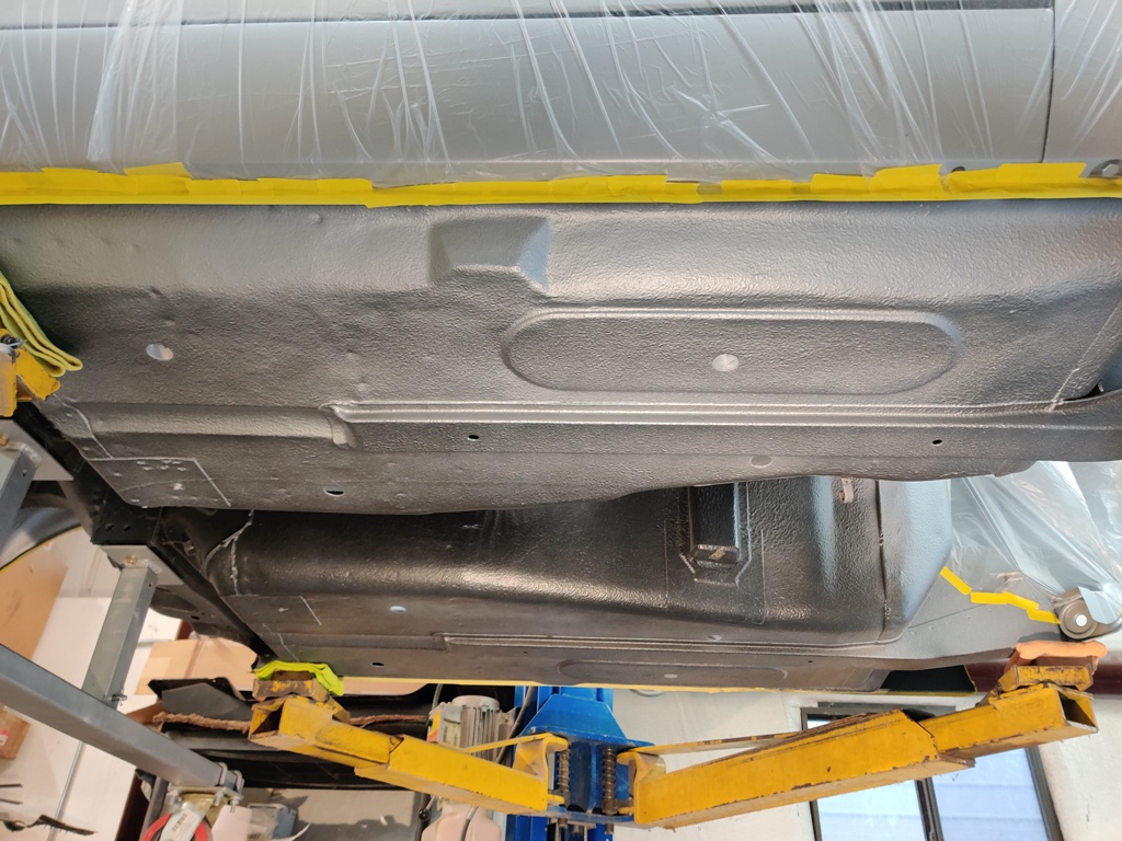
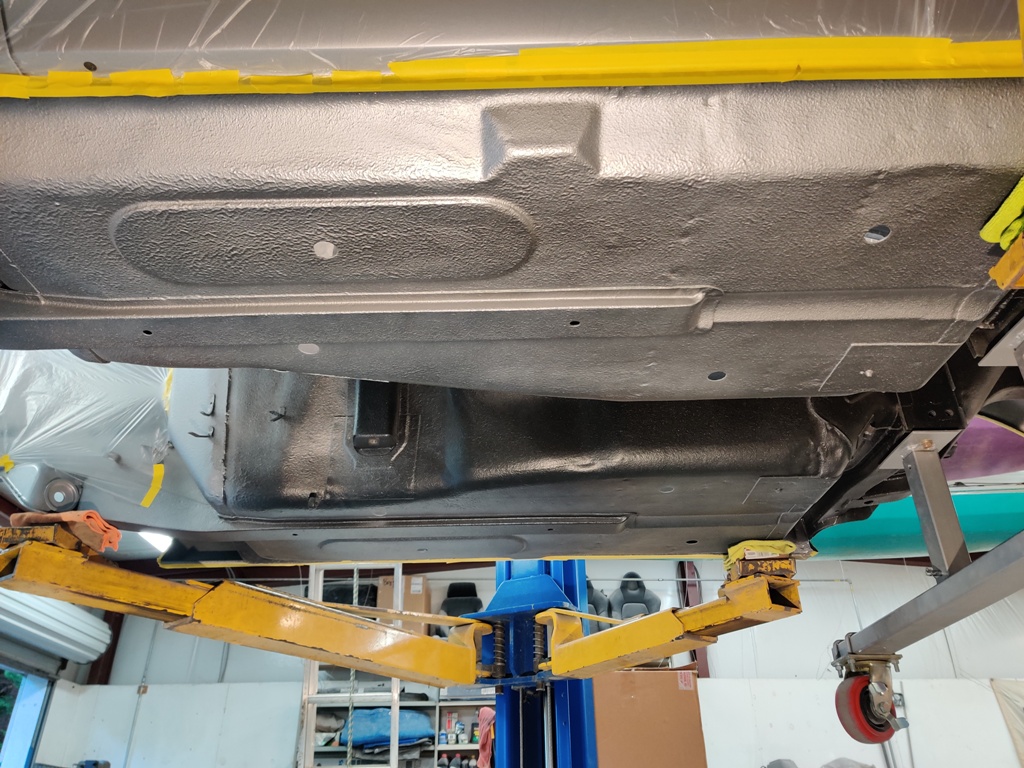
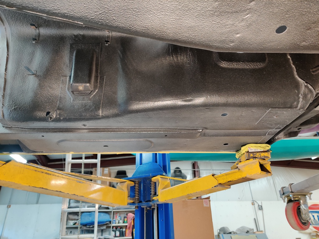
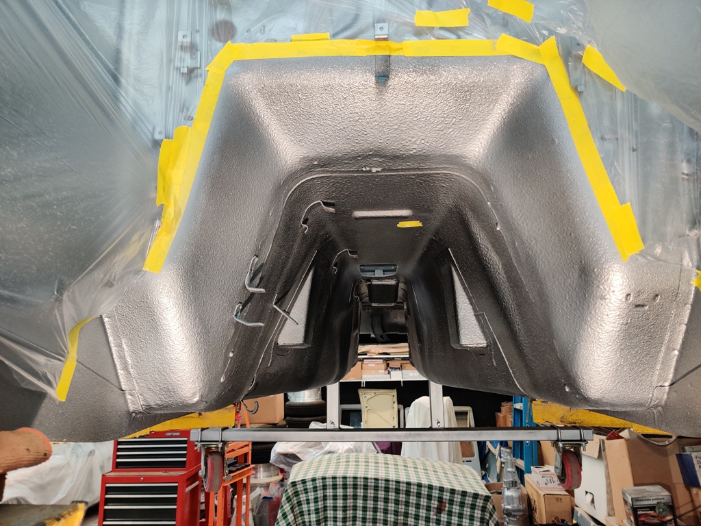
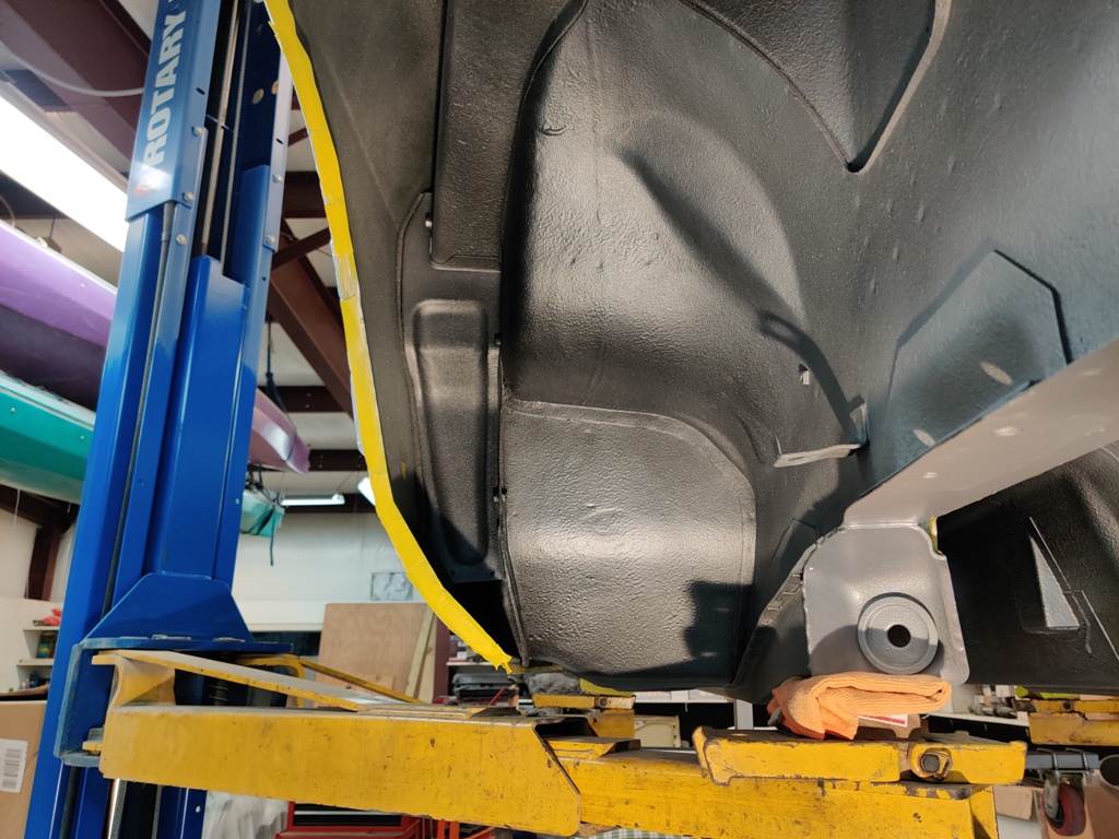
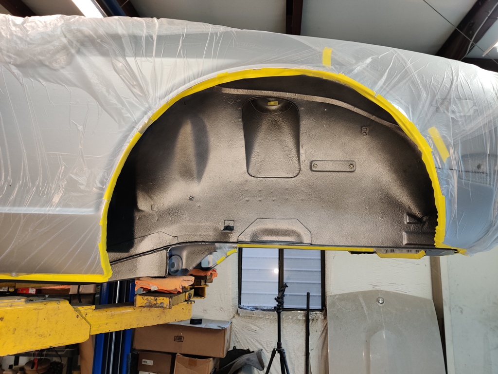
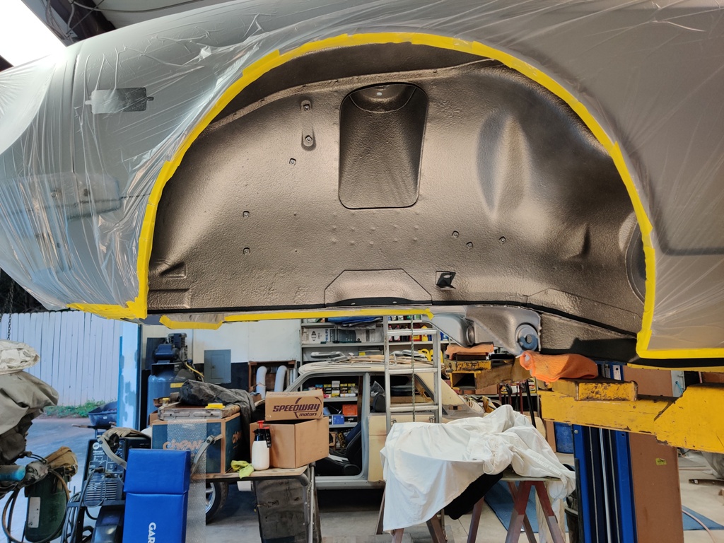
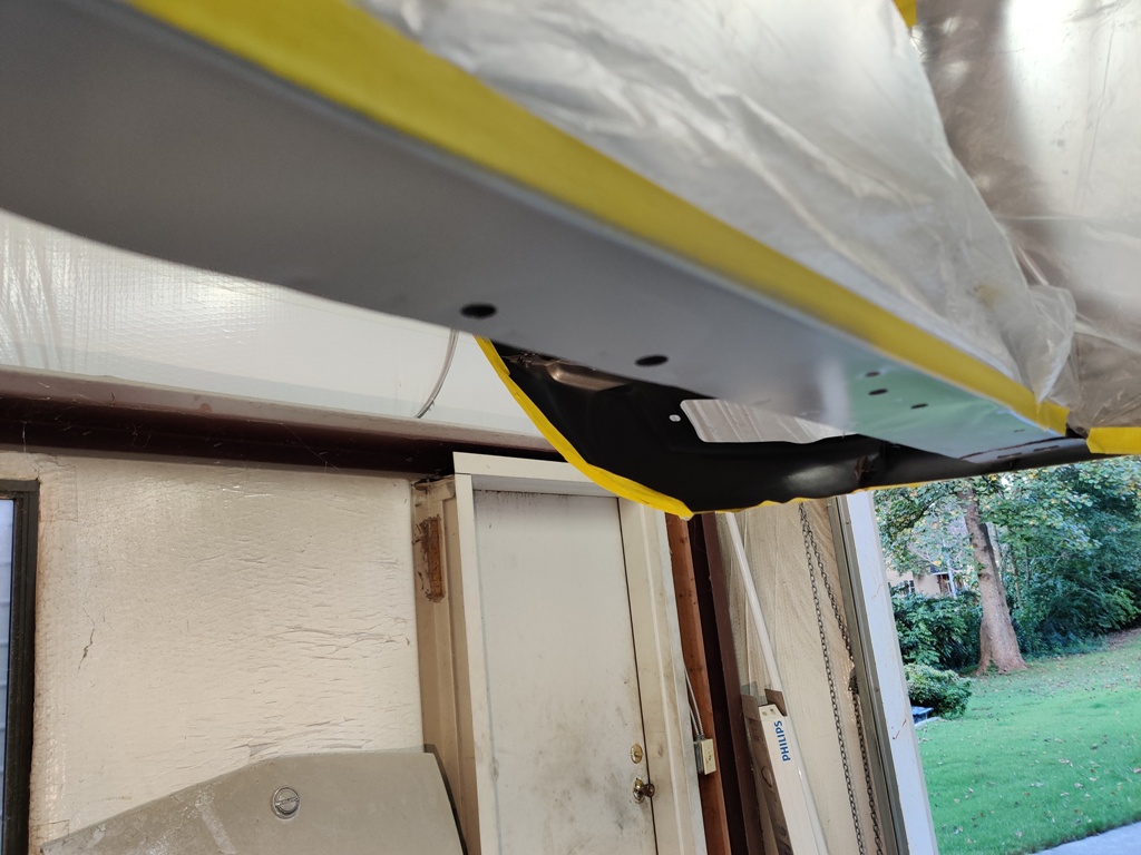
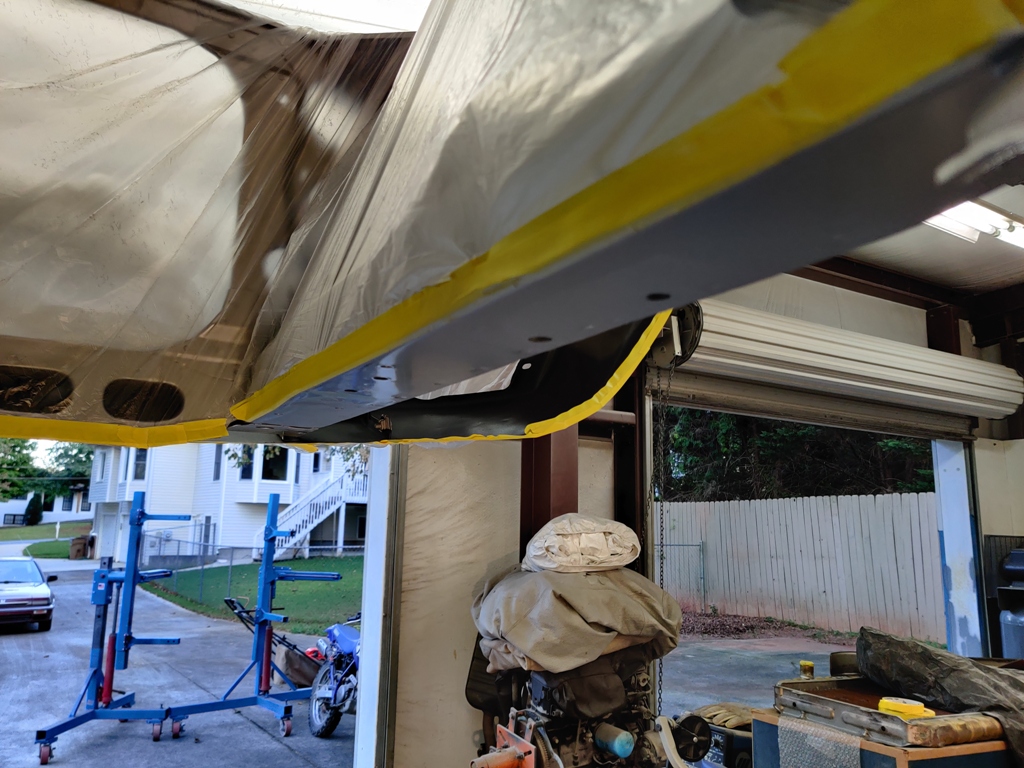
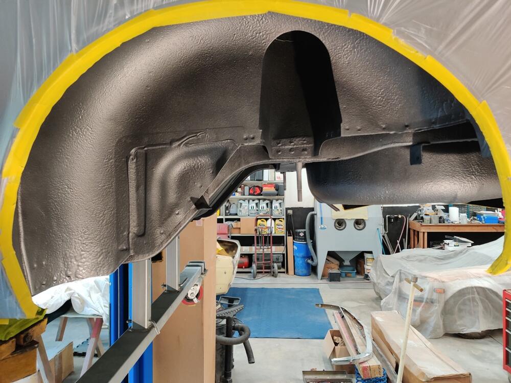
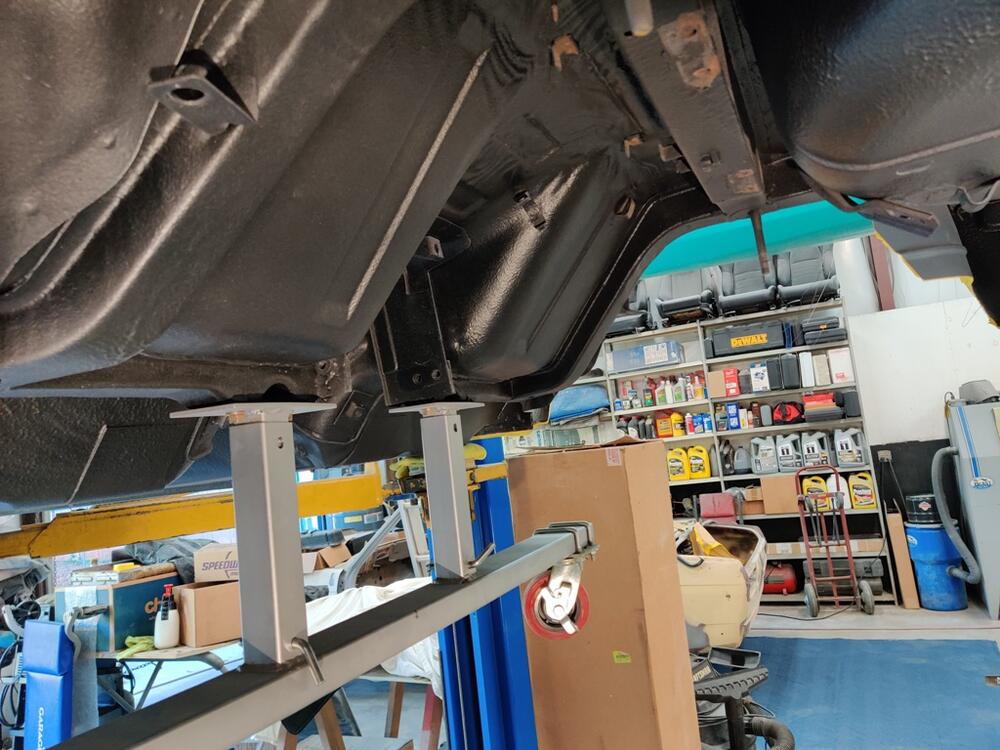
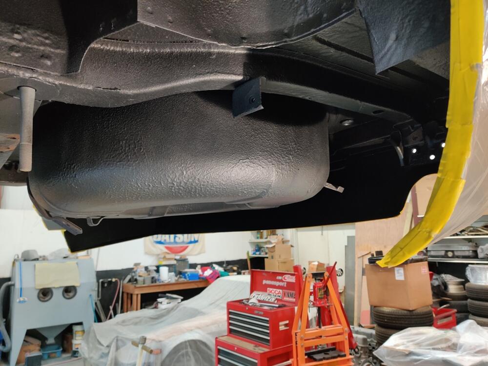
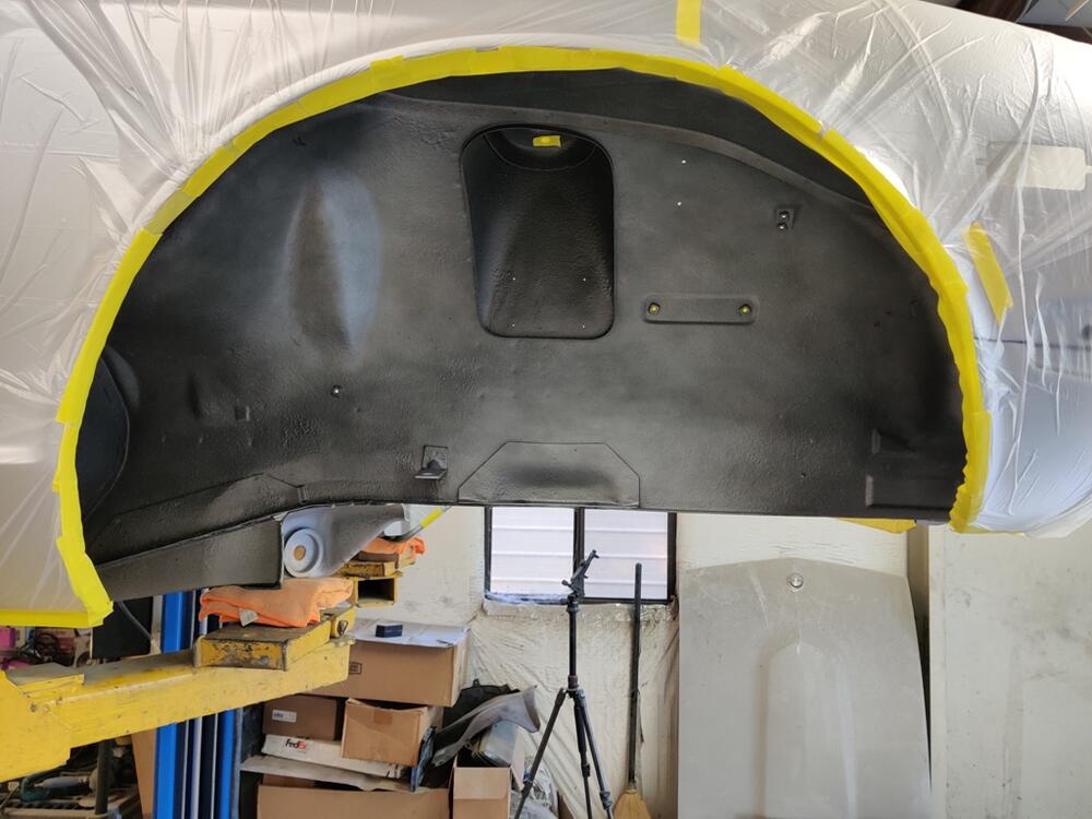
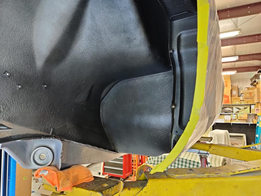
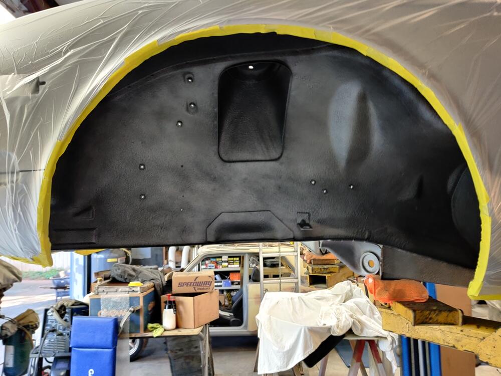
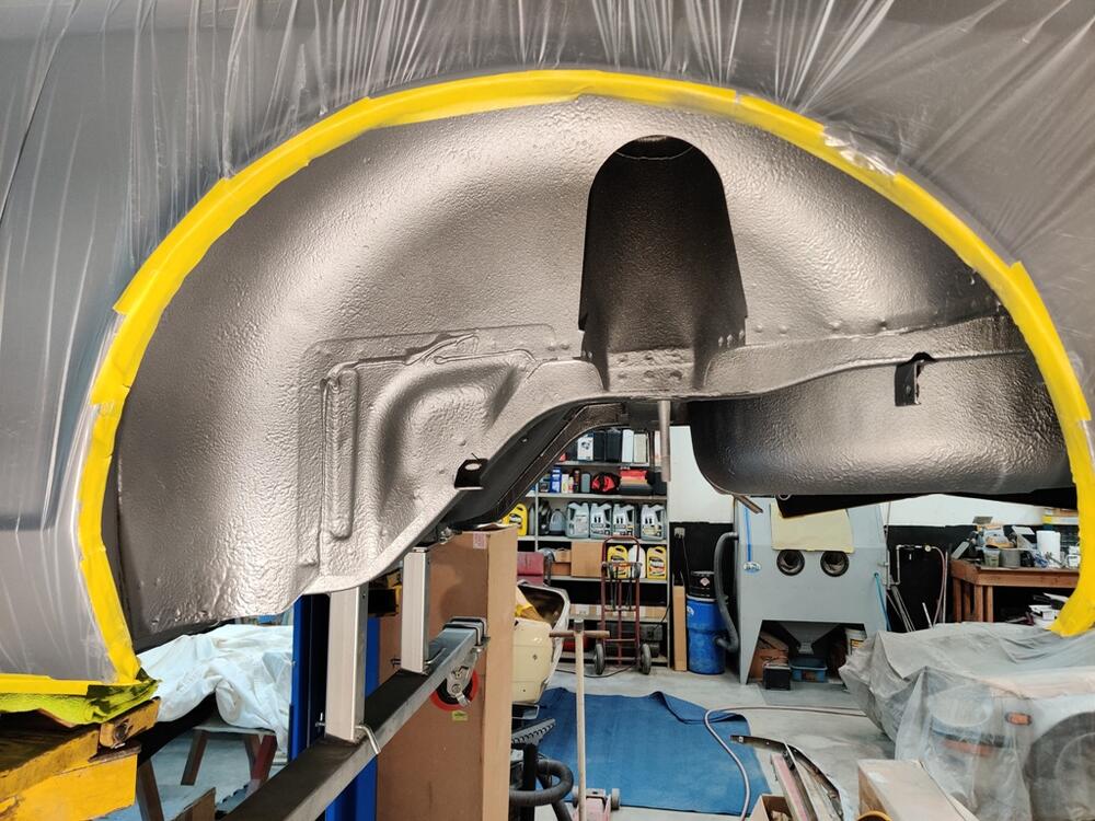
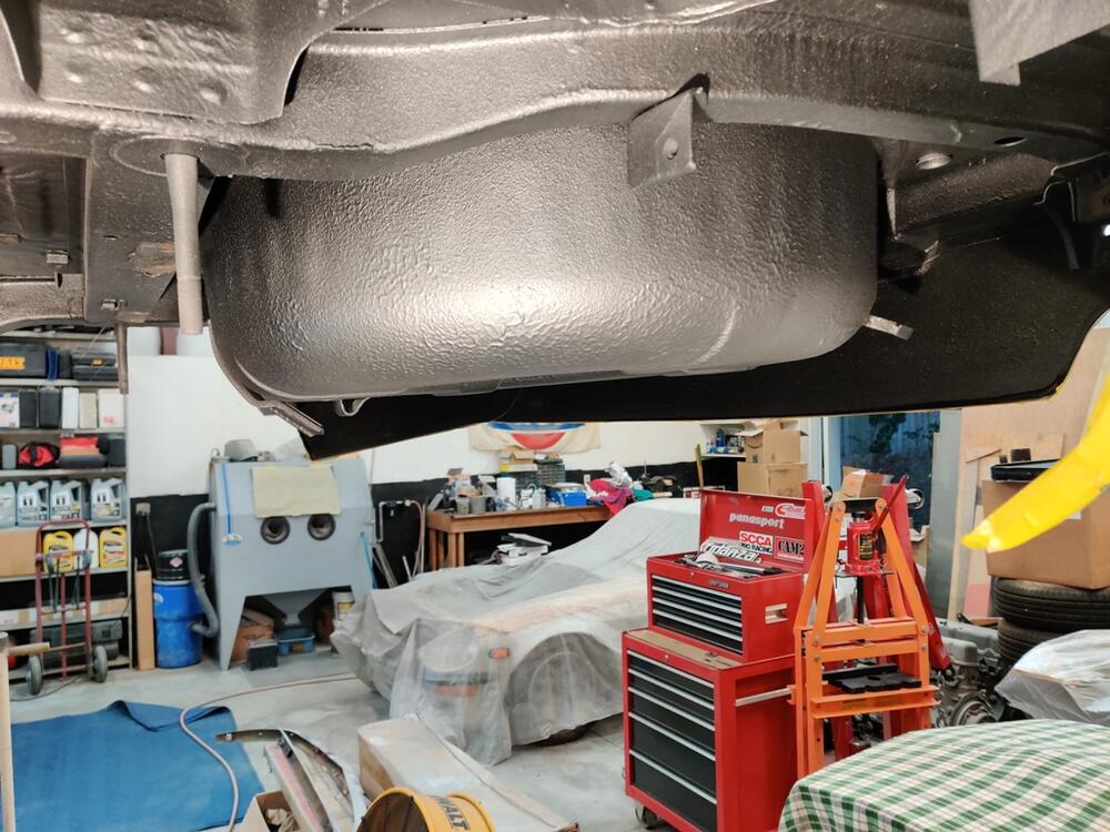
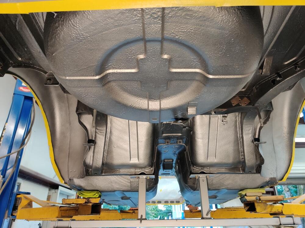
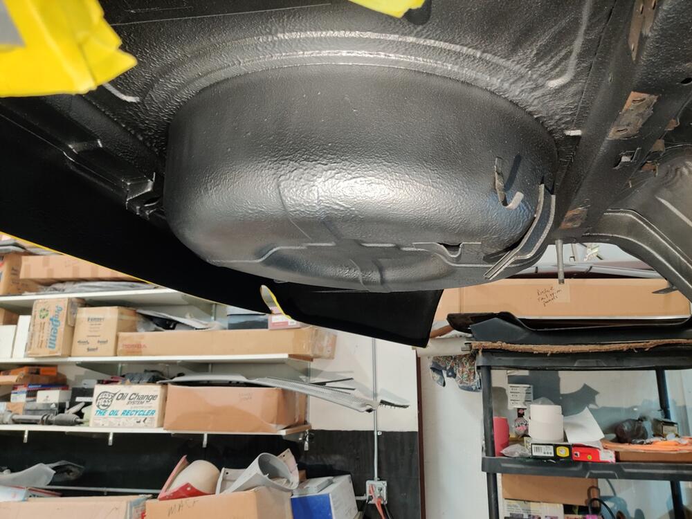
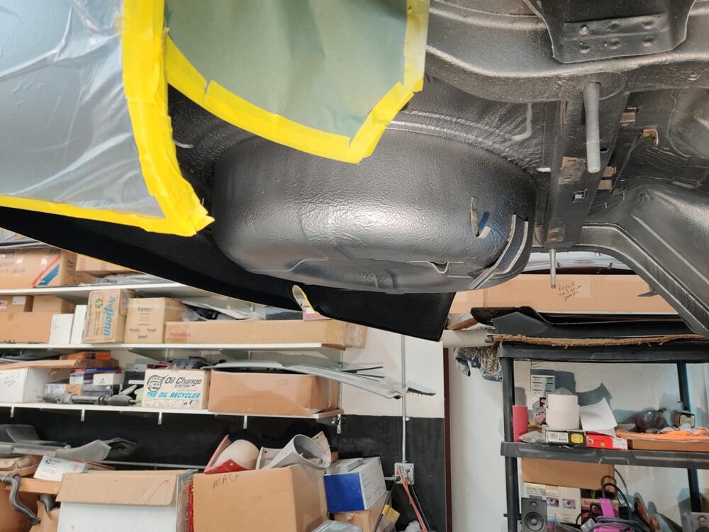
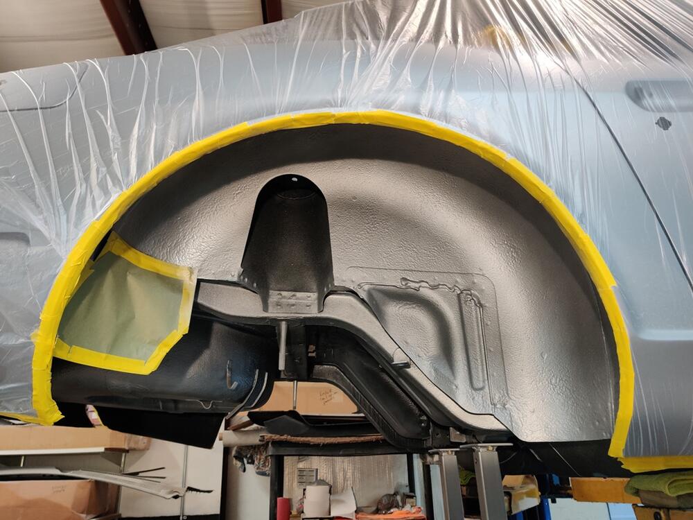
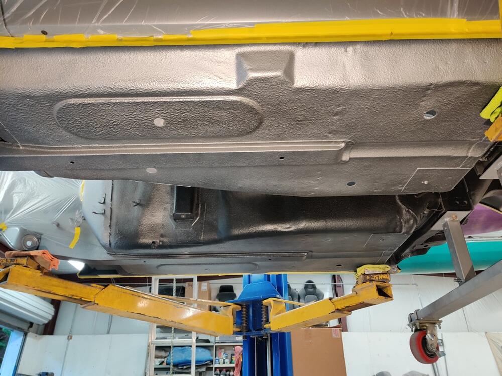
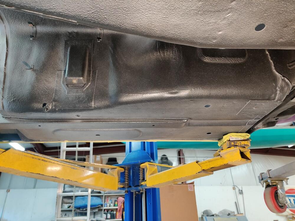
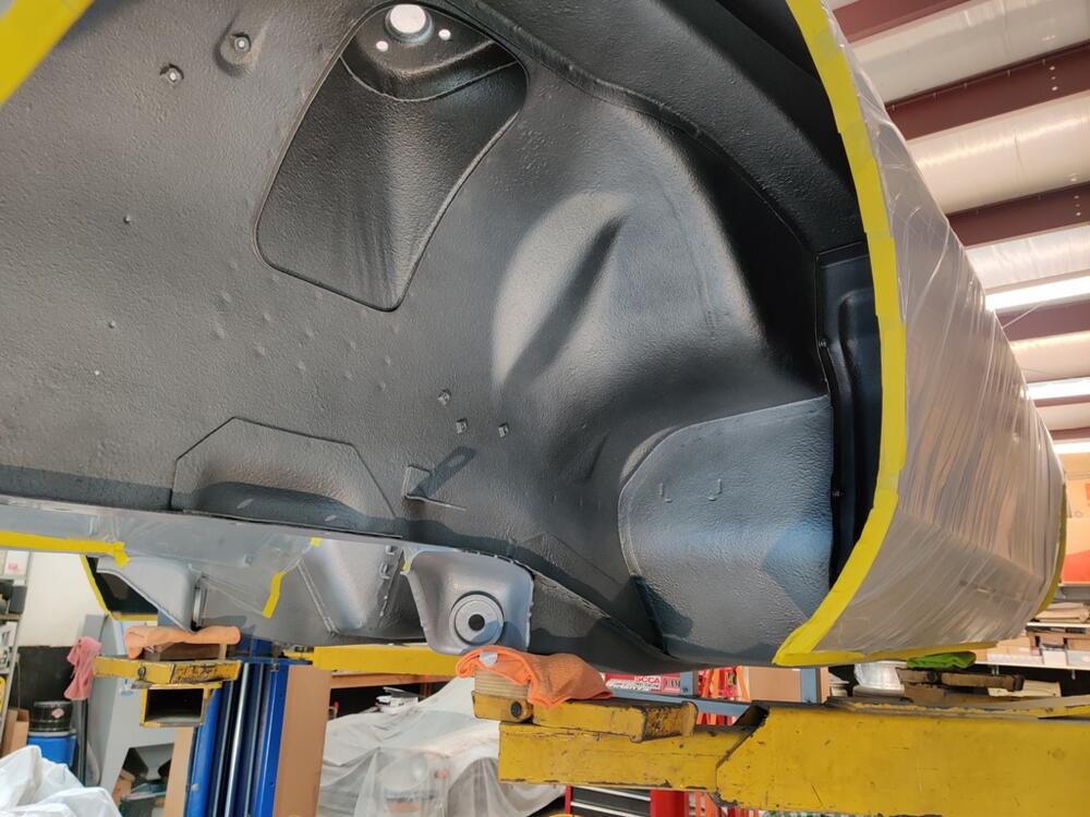
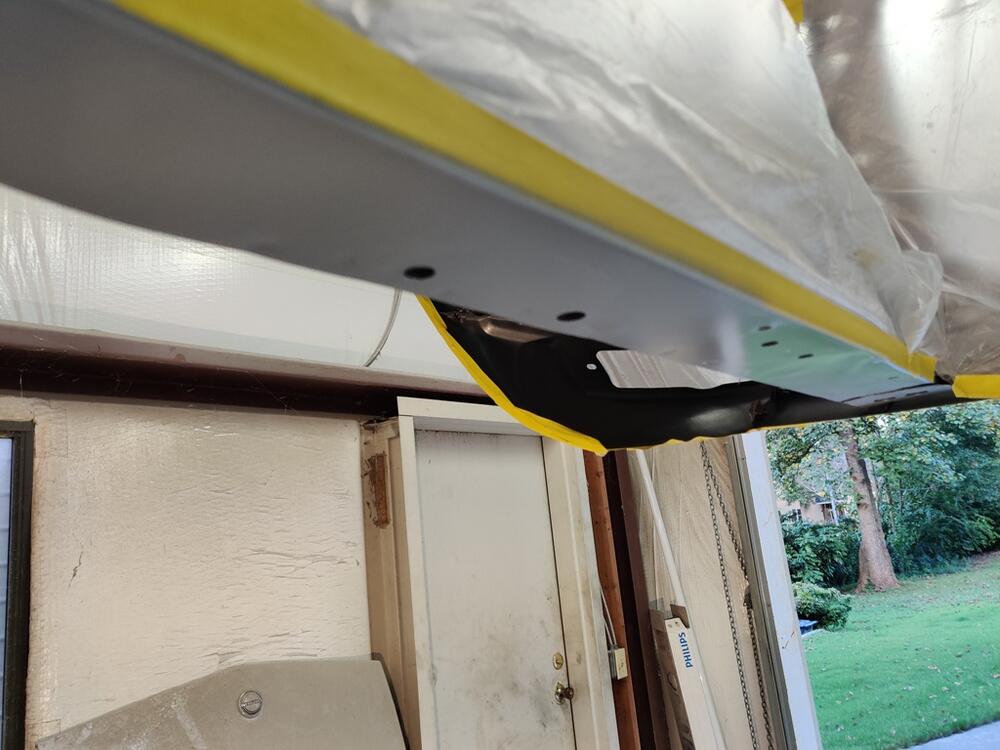
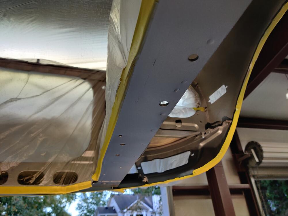
In my 21 pages of instructions to the painter (yeah, I know... it is silly - that's why I keep referencing it!), I provided a bunch of pictures of the original paint on the undersides and in the wheel wells. My thought was that while they were spraying the car, they could attempt to replicate the factory overspray. They did not, but provided me with a pint of mixed and pre-reduced paint so I could do so. Here is the before with pics taken a few hours ago. Note that most of the underside of the car is black. Along with one more pic of before, here are all of the after pictures. I replicated what I found on my car with regard to silver color - wheel wells and spare tire well mostly painted, inner part of the floors and transmission tunnel - not so much. Car dolly wasn't removed for color and clear application by the painter. So, I did remove the front dolly and touched up the bottom of the frame rail where that was bolted to the chassis.


-
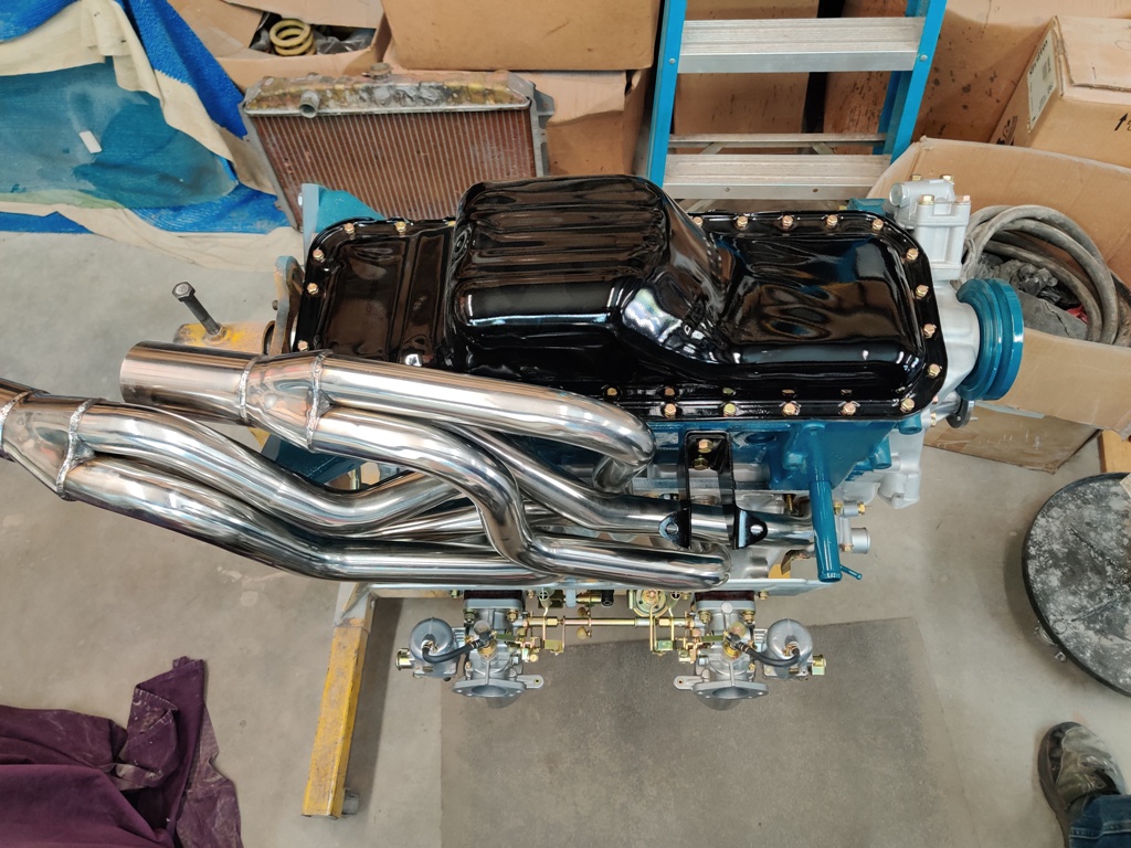
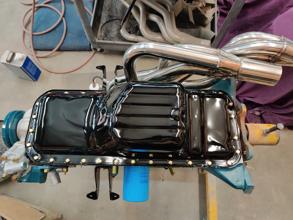
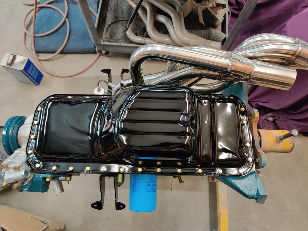
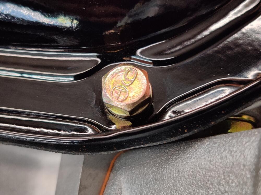
Over the weekend, I worked on the engine a bit more. The oil pickup tube gasket was missing, so I wasn't able to put on the oil pan until that arrived Saturday. All of the oil pan bolts are original. I torqued them to 42 inch lbs - a little under 4 ft-lbs. I used a Nissan competition rubber oil pan gasket. These are better than the cork ones that are typically available. The header is some kind of sexy with the engine flipped over:

-
I posted in a separate thread, but will include this in the build thread here also, along with a couple of nice pics:

-
I have the same question.
-
Three on the exterior and two on the jambs and back sides.
-
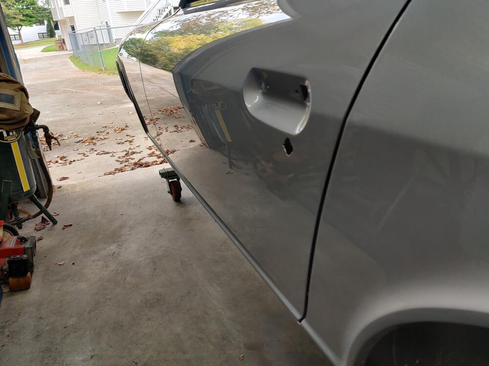
There has been a crazy amount of hours and money to get the body to this point: Color code is 901 silver. Paint is Glasurit.
-
I created a separate thread with details about the LSD installation in the R180 case. I'll be picking back up on that project soon. However, I go to retrieve the painted car body on Thursday! Here's hoping that the outcome is as good as I have wished for.
-
I measured the turning torque on the pinion nut tonight. Factory spec without the oil seal is 7-10 kg-cm without the oil seal in place, or 6.1 to 8.7 in-lbs. I measured 15 in-lbs. I think that is a bit much based on a Youtube video I watched, where before installation and after installation of the pinion oil seal, the turning torque was measured at about 14 on an R200. I will back the nut off some, torque the nut to the low end of the factory range instead of 135 ft-lbs, and re-measure. Will try to get it to be around 10 in-lbs.
-
My headlight housings (sugar scoops) had never been off of my car before I took them off. There was no sign at all of a gasket there. In fact, I could tell from the original factory paint that the scoops were on the car (and bolted tightly in place to the front of the fenders) when it was painted at the factory. I don't think any rubber gasket was used between the sugar scoops and the fenders. Never seen one in all the years I have been internet surfing Datsun Z's either.
-
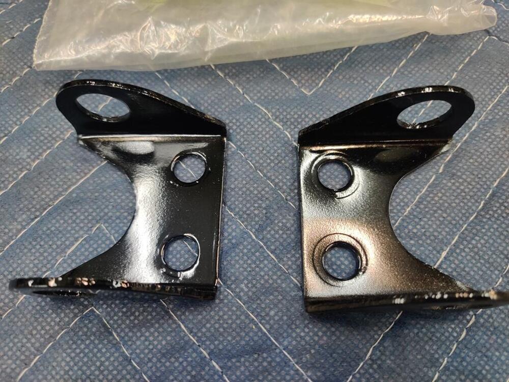
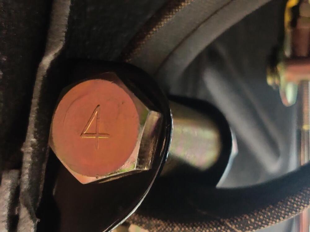
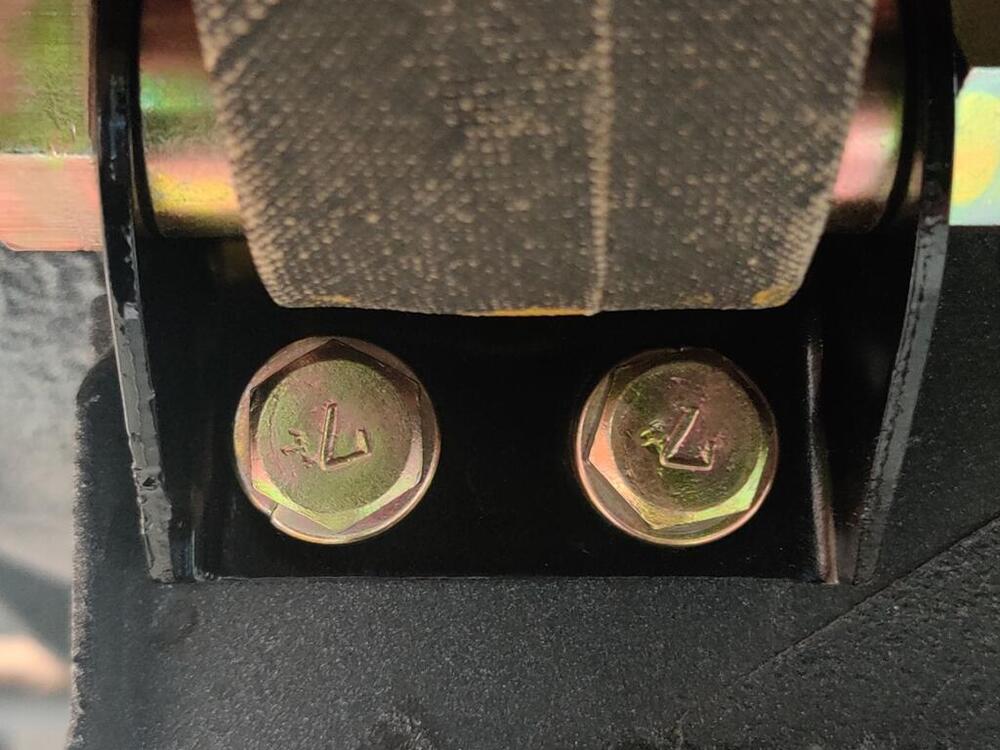
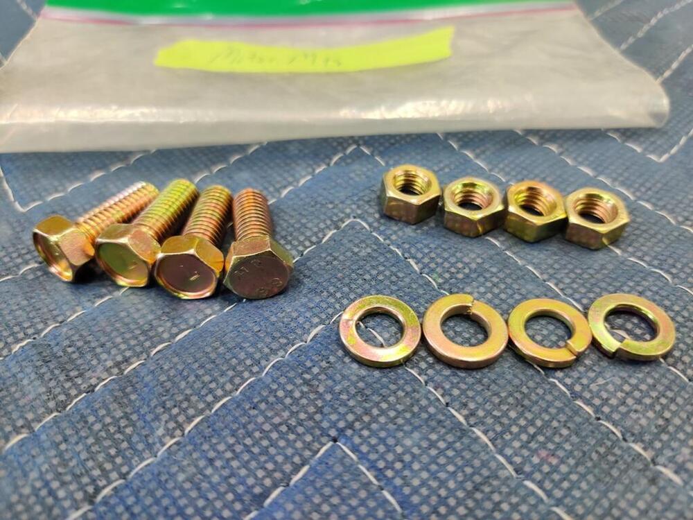
Really great work you are doing! I like your part number on the moustache bar - came out nice.
-
I have some gear marking compound coming also. I plan to check rotation torque and adjust if necessary by backing off the pinion nut a bit and retorquing. Then, I will assemble the carrier in place again with no shims on the left and all on the right. I'll check back lash for kicks (because I am sure it won't change). And then, I will put the gear marking compound on and see what's what. My guess is that the pinion height has changed, probably due to differences in the pinion bearings. I don't know how (at the moment) to figure out what to change with the pinion shims. I will research.
-
Thanks, I found some relevant posts. One of the frequenters of that site said, "It's been my experience that the backlash doesn't change notably. It changed .0005" on my own diff, and I've never come across any posts from someone whose backlash needed to be readjusted after installing the LSD." Before disassembling to remove the paint from under the side retainers, I measured the back lash, and it was about .014". The factory spec is roughly .004" - .008" (the factory service manual is not near me right now). I then removed the side retainers and scraped off the paint with a razor blade, and reassembled. After doing so, I put the side retainers back on, snugged the 5 retaining bolts, and measured back lash at .020". That was surprising to me, but I figured maybe I didn't measure it properly the first time. The factory workshop manual says that if there is too much back lash, to move shims from the left retainer to the right retainer. As assembled from the factory, the left retainer has one shim that I measured at .011" thick. The right retainer has two shims, one is .016" and one is .020". So, I took the side retainers off again and moved the shim from the left, and stacked all three on the right. I reassembled and measured back lash at .012-.013". Darn it. I found several pages back in this build thread, where I measured backlash before disassembling this diff, and it was .005". So, referencing the info from the Hybrid Z post, I appear to be in an unusual situation where swapping out the open carrier for an LSD has perhaps changed things substantially. Of course, in this instance I changed pinion bearings, so perhaps the pinion height has been altered now. As a next step, I will measure the turning resistance on the pinion shaft to rule out that I over torqued the pinion nut and have too much pinion bearing preload. I ordered a torque wrench which should allow me to check that properly - it will be here Monday. However, I don't have much hope that the amount of preload on the pinion bearings is my problem. Doing something other than using the shims that came with the differential is a departure into the wilderness - this is not something I have ever done before. So, I really am feeling lost about how to get this diff set up properly at this point.
-
Can anyone else corroborate? I have never seen this before.
-
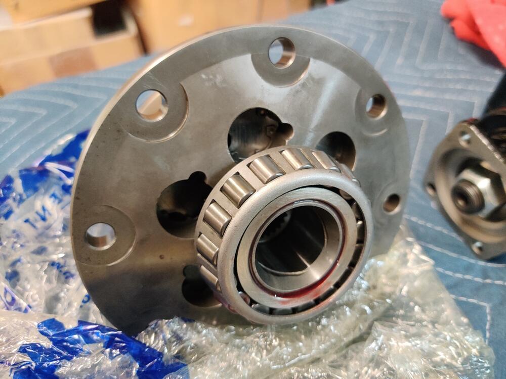
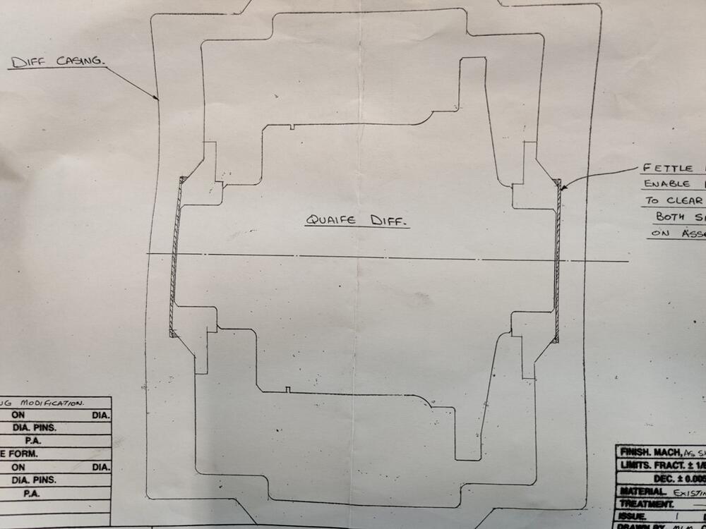
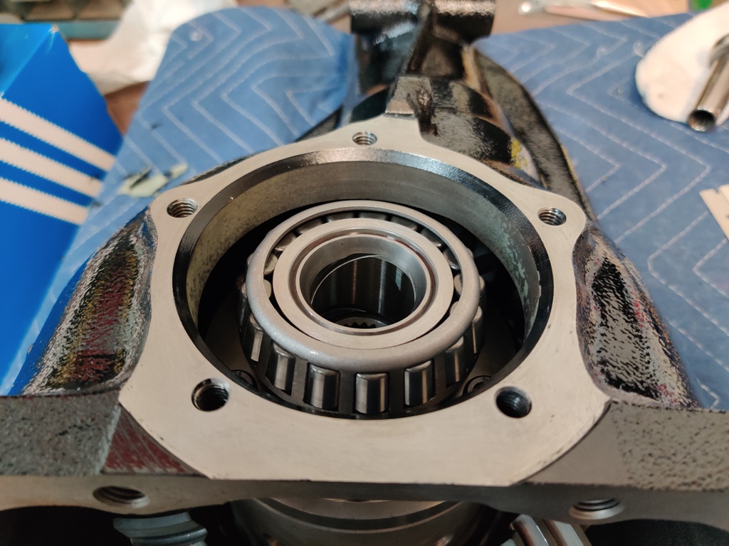
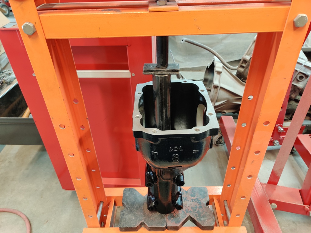
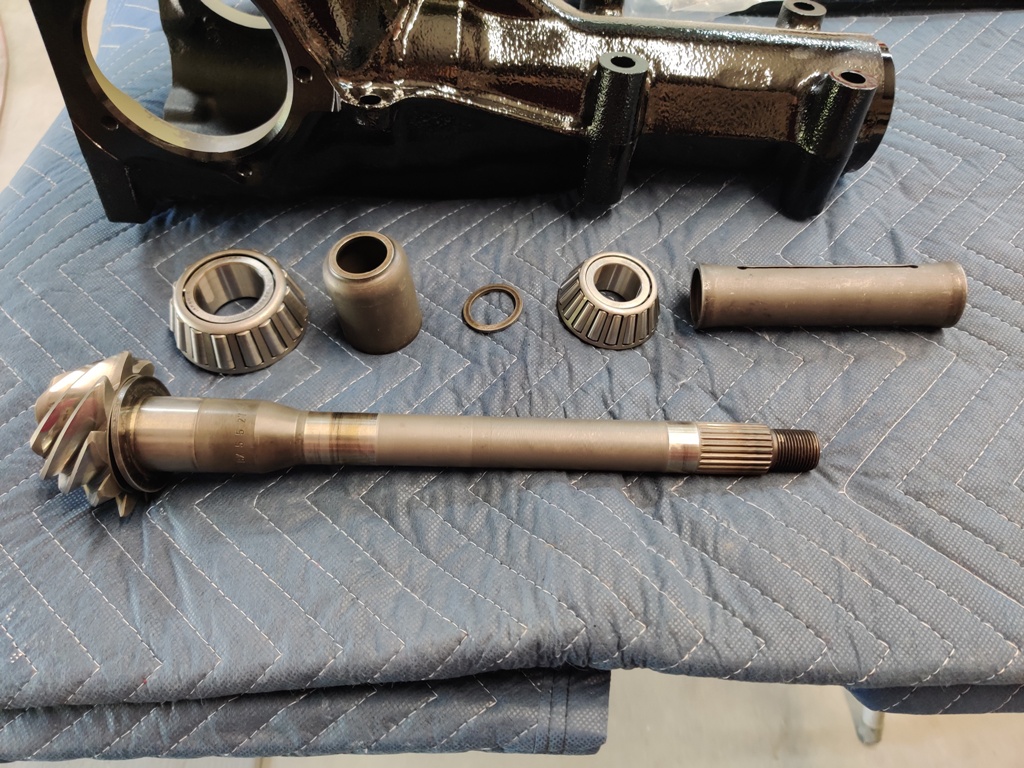
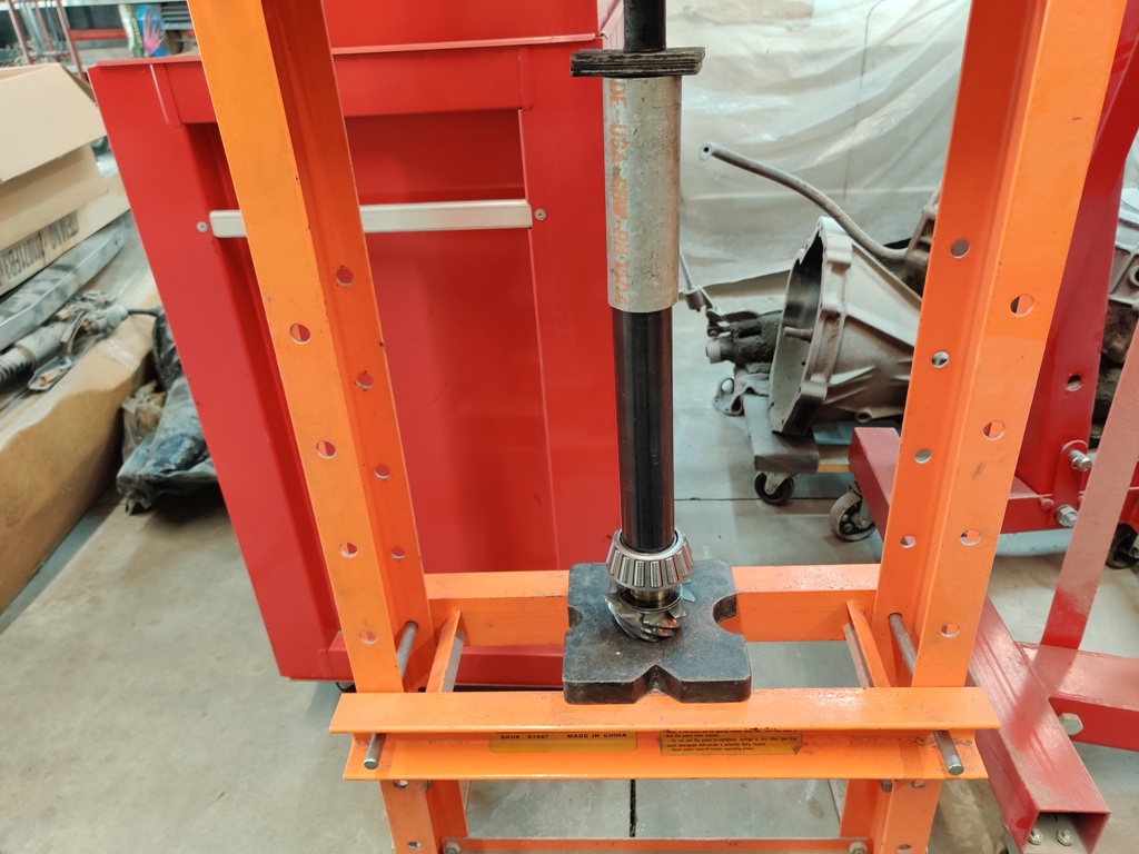
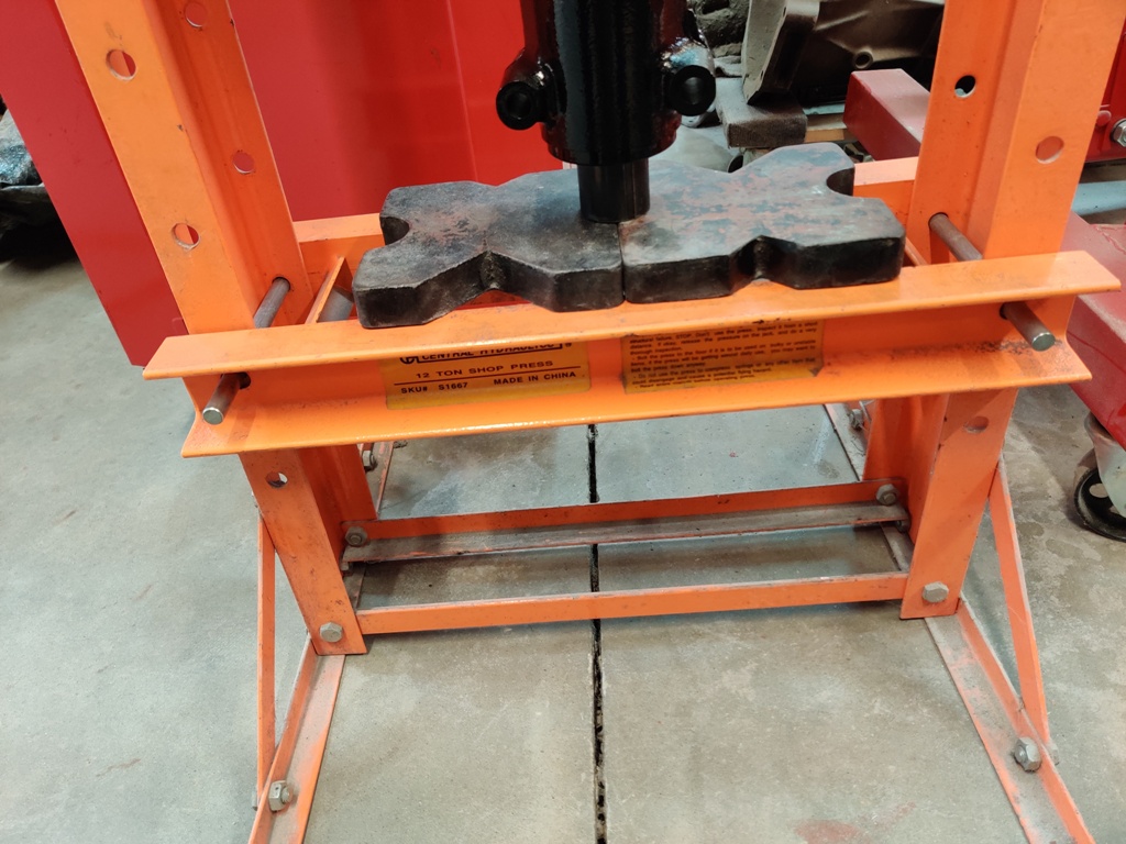
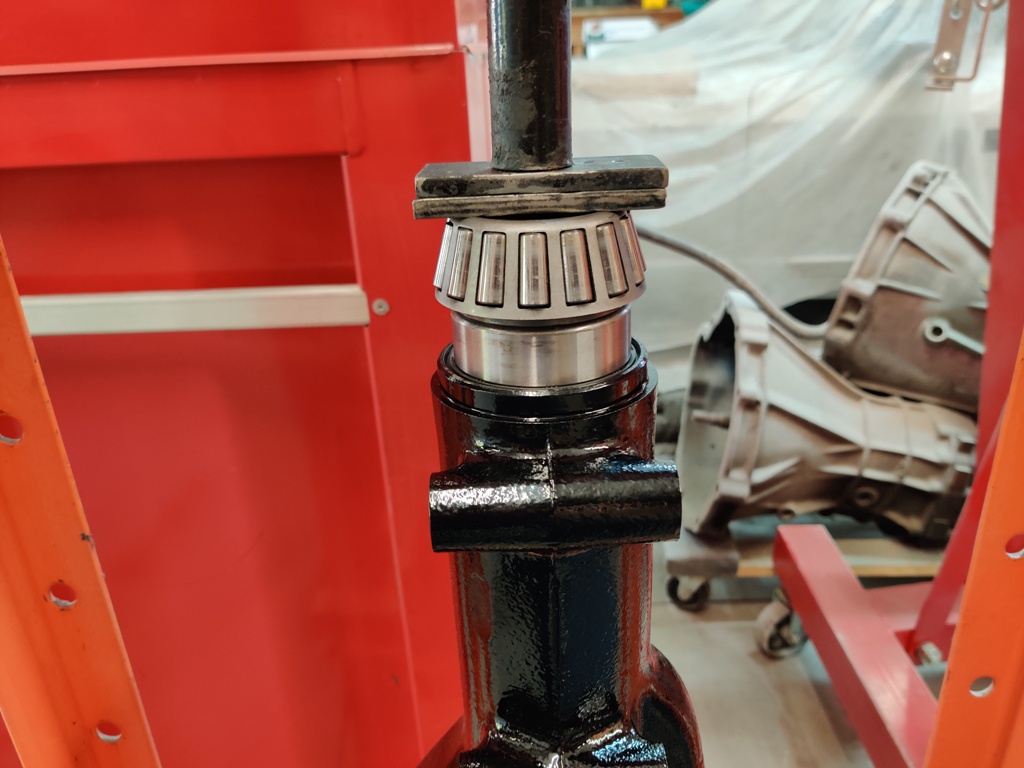
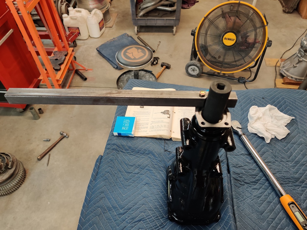
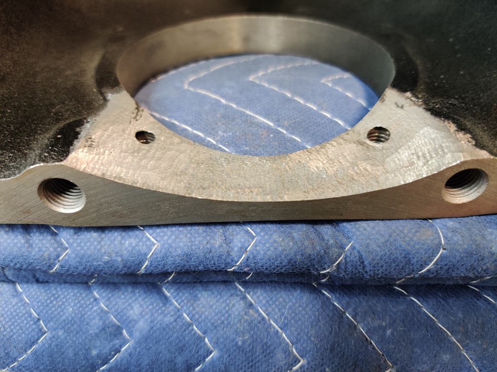
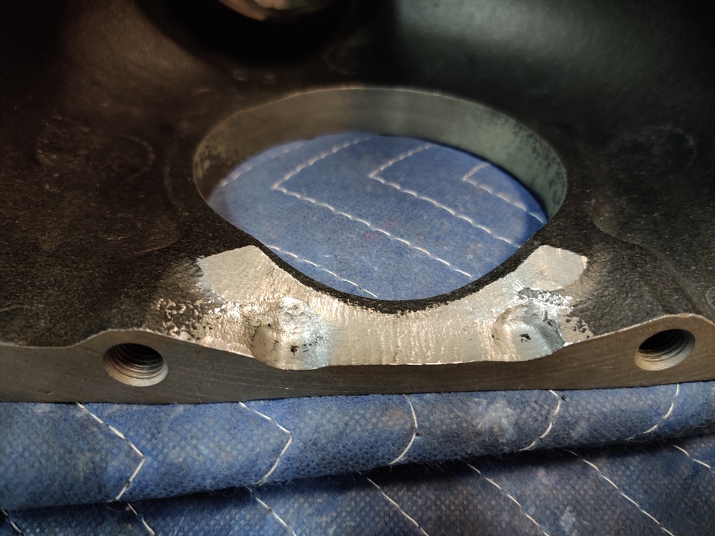
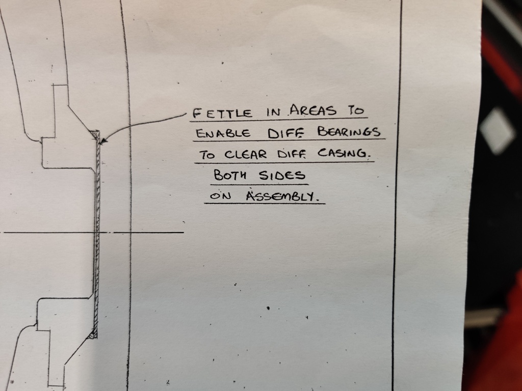
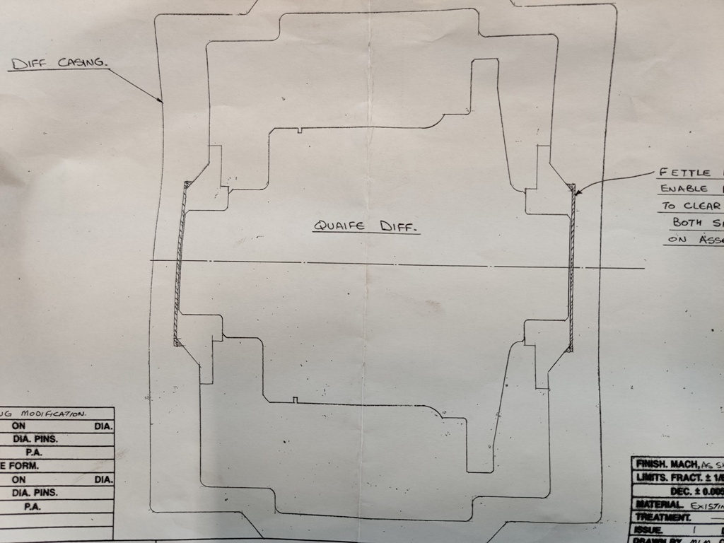
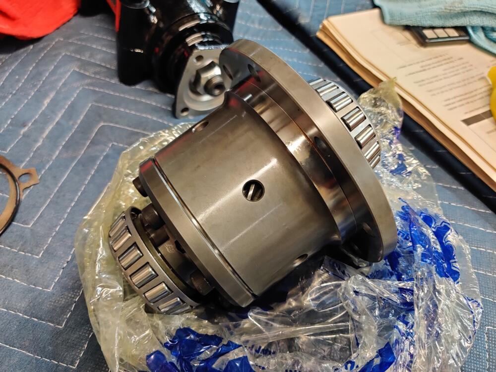
I have been rebuilding my differential for the last couple of evenings. It is a "K" R180 from the front of a Nissan 4X4 truck. From running it in my 240z, I know it was in good condition before disassembly. And, when I took it apart, I checked backlash and it was within spec. So, I don't believe it ever had been apart before. I purchased a Quaife LSD for it. I also purchased all new bearings and seals. For the differential case and the drive pinion shaft, I was very careful to install races and the tapered bearings, fully seating them in their correct positions. I also was sure to use the spacers and shims that were removed back in their original locations. Using old bearing as an installation tool for the front pinion bearing. Using a homemade tool to hold the pinion from turning while setting the torque to 135 ft-lbs (factory manual specifies 122.9 -144.6 ft-lbs_ To get the Quaife in the case, it was required to "Fettle": It took a lot of fettling, but I very carefully ground only where needed until the carrier just fit. In fact, I had to leave one of the main gear bolts off until the carrier was partly in the case, and then torque that last bolt through the side axle opening. This fettling was an unpleasant surprise that added 4 hours of time to grind on the case. I had to be extremely careful with packing the case cavity and other preparation to keep the metal shavings from the carrier and from installed pinion shaft (and bearings). At this point, and here is where I stopped, I have installed the side retainers, left and right, with their respective shims in their original positions, with the 5 bolts on each just snugged down, not torqued. Now, I could use some guidance. What I have not done that I may need to: I didn't measure the amount of turning force on the pinion shaft. I don't have a suitable tool to measure that. I see that this is supposed to be done without the pinion seal installed. I have already installed that. There is preload on the pinion bearings - I can tell by rotating the shaft by hand. I just don't know how much. I did not remove the fresh paint (and primer) from the sides of the case where the side retainers seat. I am wondering if those thousandths of an inch matter. Given the side retainer shims originally used are quite thin, paint in this location may be an issue? I didn't measure the amount of main gear backlash with a dial gauge yet. I just moved the main gear by hand back and forth. Doing so, the amount of movement is noticeable. I'd guess .015" to .020". I do have a dial gauge and magnetic base and plan to measure the back lash when I pick back up on this. I was hoping, perhaps naively, that I would be able to use the existing pinion and side retainer shims even with replacing the stock carrier with the Quaife LSD unit, but it looks like I have more work ahead of me. The factory shop manual is difficult to understand, and I don't have the factory tools being referenced. Anyone have any guidance on how to proceed? I am thinking about buying the tool to check pinion turning force. I am thinking to not removing the pinion seal, because I would likely destroy it in the process, but instead just factor in 1-2 additional inch-lbs into the reading I measure from having that in place. So, if I measure 2 inch-lbs more than the factory upper limit, I'd call that good, for example. I am also thinking about removing the paint from under the side retainers and reinstalling them with fasteners torqued to spec to check the main gear lash measurement. From there, I may need to order various side shims and attempt to get back lash correct? Then check the gear mesh pattern to see if everything is set up the way it should be?


-
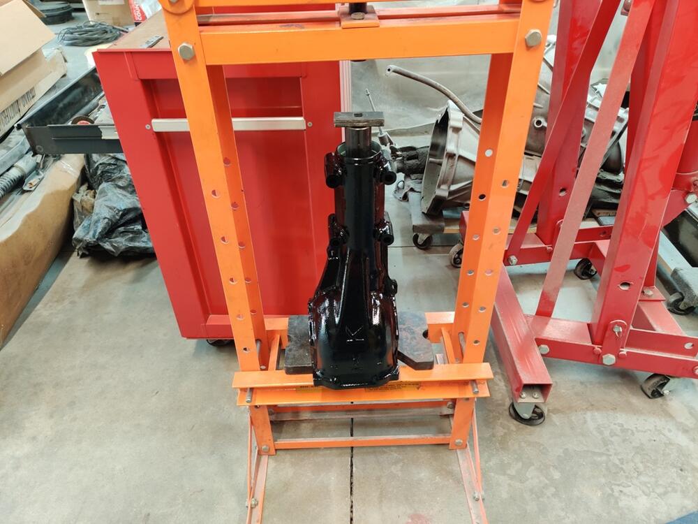
Well, I tried fitting the carrier inside the differential case, and it doesn't fit, but not by much. I think more than roughness of the casting will have to be removed, like with a high speed die grinder. I have already installed the pinion and related bearings. So now, if I have to grind away material, I will have to seal the pinion and all cavities within the differential case to keep bits of sharp metal from finding there way in there. I haven't found any info online about this "mod" to make this unit fit.
-
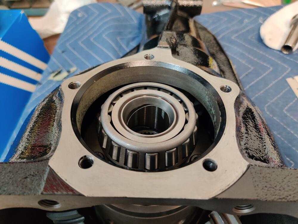
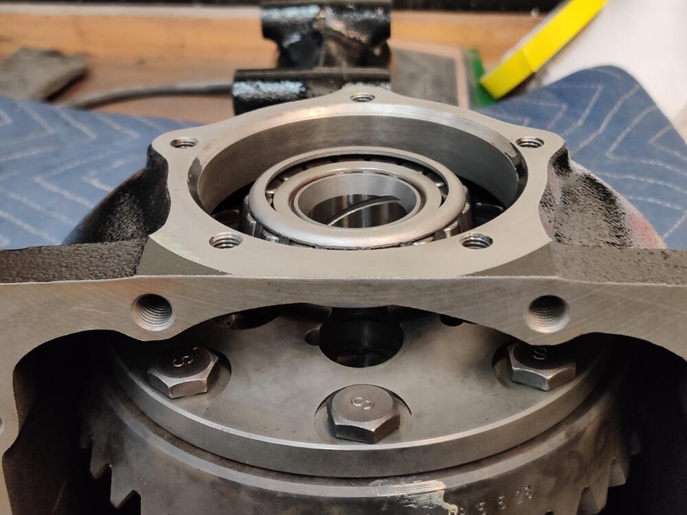
I am progressing with the differential assembly. What the heck is this??? uh oh.