inline6
 Subscriber
-
Joined
-
Last visited
Everything posted by inline6
-
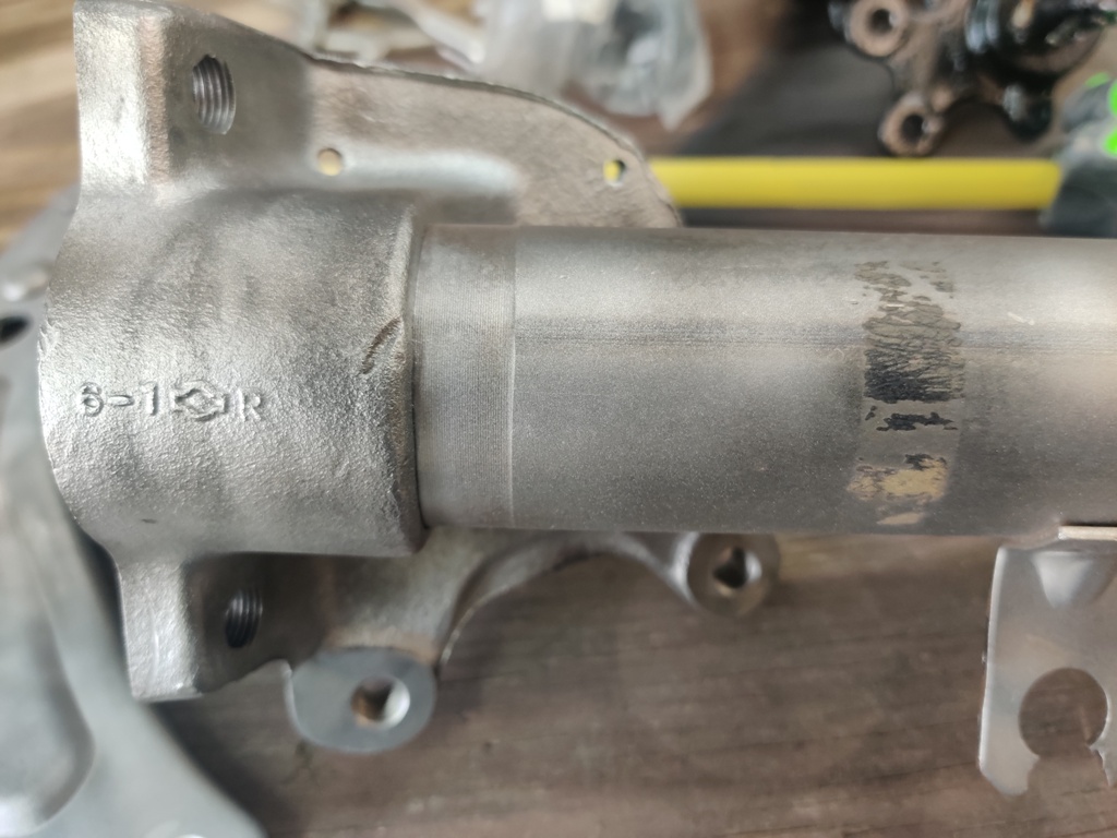
 My trusty compressor developed a problem with its pressure switch. The contact started sticking and the compressor kept running even when the tank pressure exceeded the cut off pressure. I've had it for about 27 years, and used it a fair amount given I am just a hobbyist. I am too lazy to get a picture of it, but it is this same model - though I think it was branded under Campbell Hausfeld: So the switch - I went online looking for replacements. The original switch had the model "DAC-278-1" with number 140 and 175 which apparently indicate the turn off psi and turn off psi. Since I bought it new... for 27 years, it turned on around 120 psi and turned off at 155 psi. Tonight, the $18.95 replacement arrived and I installed it. Here is the one I bought: https://www.amazon.com/dp/B00273R6KU?psc=1&ref=ppx_pop_dt_b_product_details Interestingly, this switch kicks the compressor motor on at about 145 psi and turns it off at about 175 psi. And this one, has screws to allow adjustment to the turn on and turn off points. My question is this, is it harder on the compressor to utilize 145/175 instead of 120/155? It seems logical that to get to 175, it has to run longer than to get to 155. But, if it kicks in at a higher pressure also, maybe it ends up running the same amount of time when air is not being used? And then, there is reality - I consume air while it is running quite often, like for sand blasting or glass bead blasting. And pretty much all of my tools are limited to 90 psi... So, is it wasteful or unnecessary to run 145/175? For what its worth, my lines are cast iron pipe and the water separator and regulator are rated for 200 psi max, the hose is rated sufficiently high enough, etc.
 -
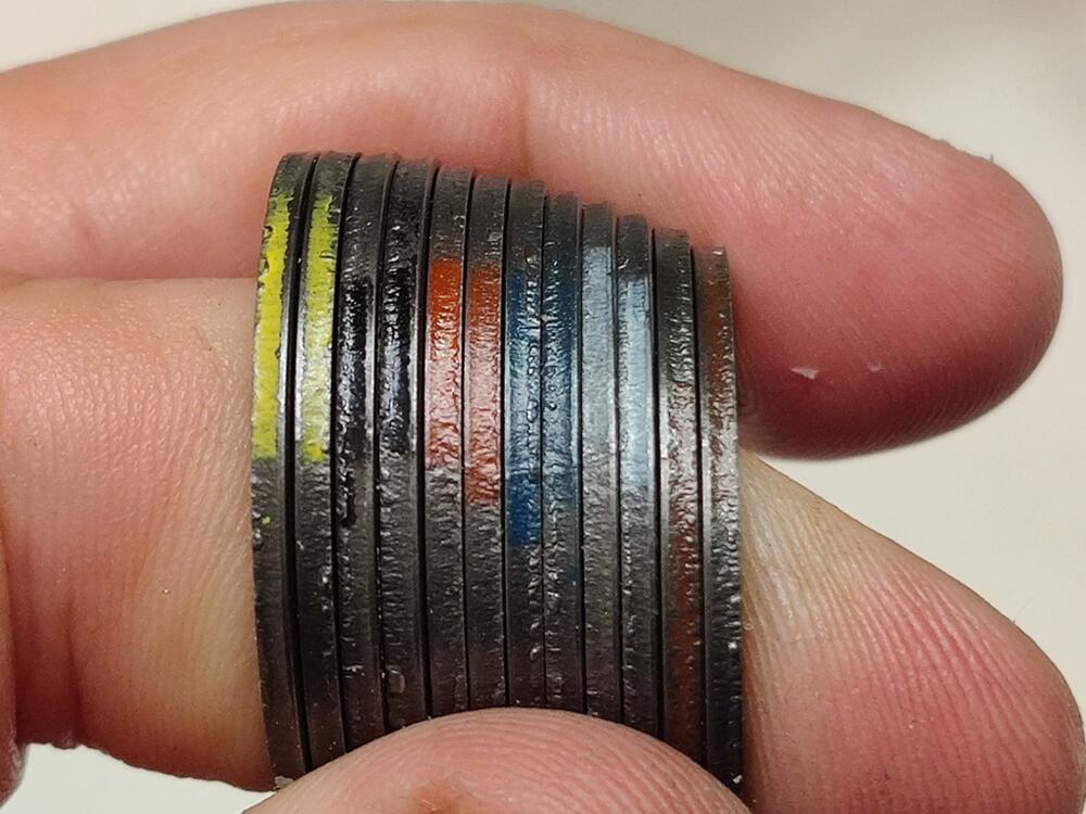
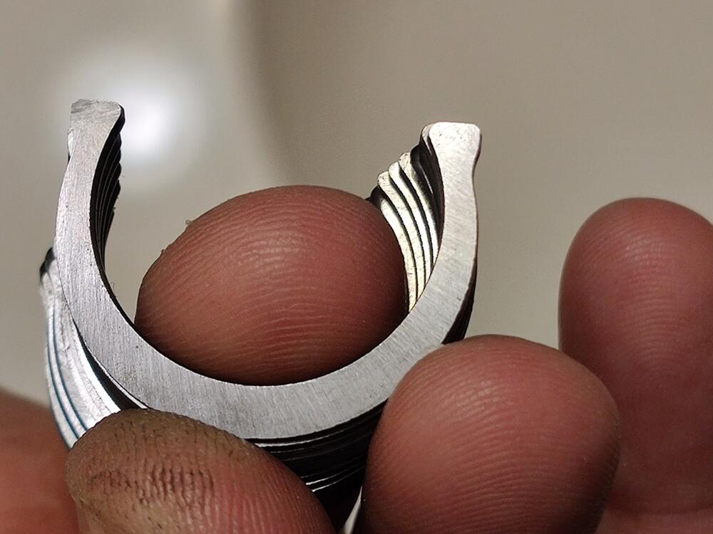
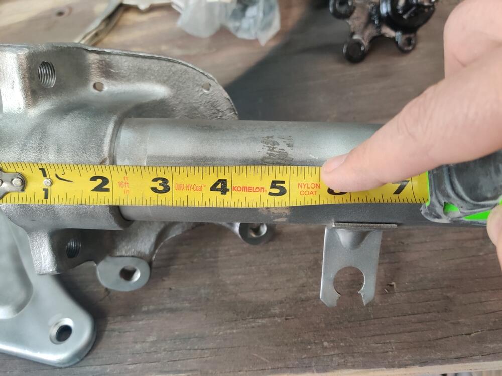
I find it curious that the snap rings supplied with the new u-joint are in thicknesses which are paired in twos and thicker and thinner than what I took out. Possibly they were trying to supply a broader range on purpose. Consider, why not provide 3 groups of 4 of the same size, for example? I am going to take some measurements of the distance between the yoke ears or whatever you call them. Perhaps the distances vary a bit and will give me guidance on what thickness snap rings need to be used. It will be interesting to see variances.
-
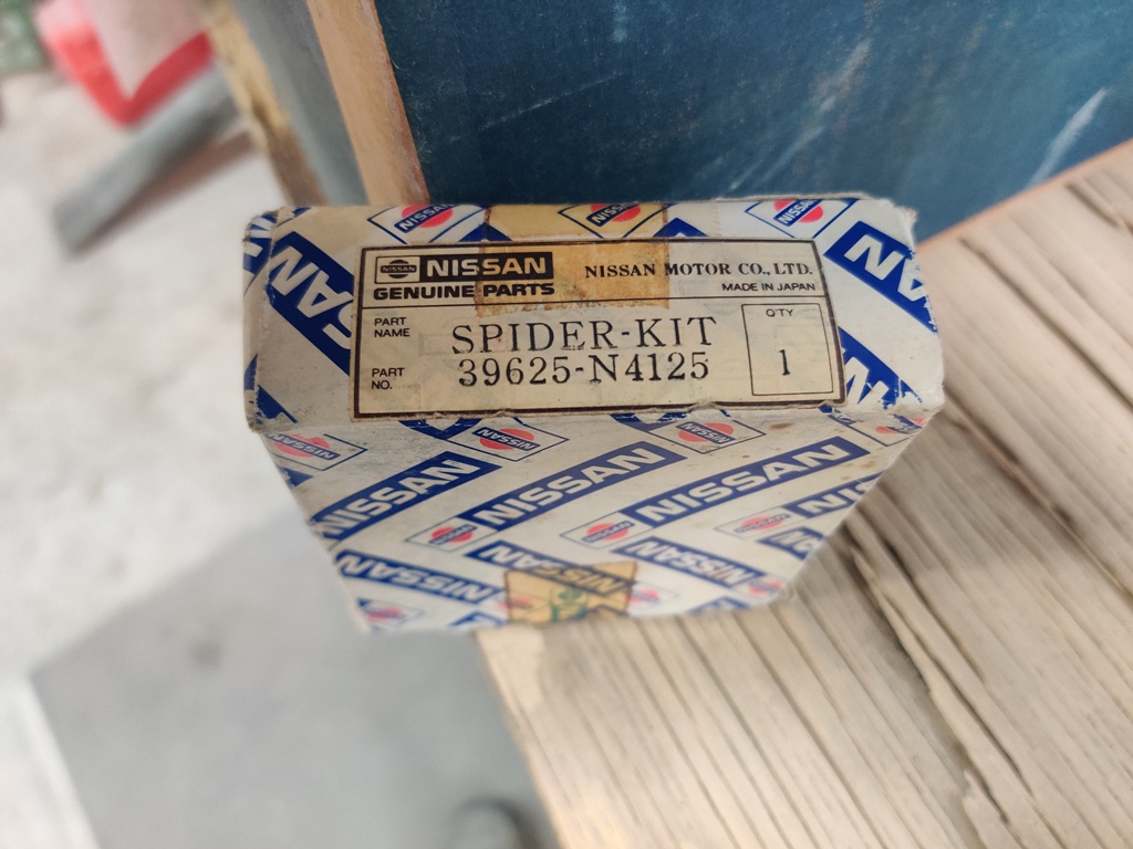
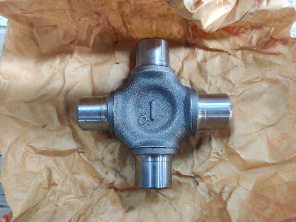
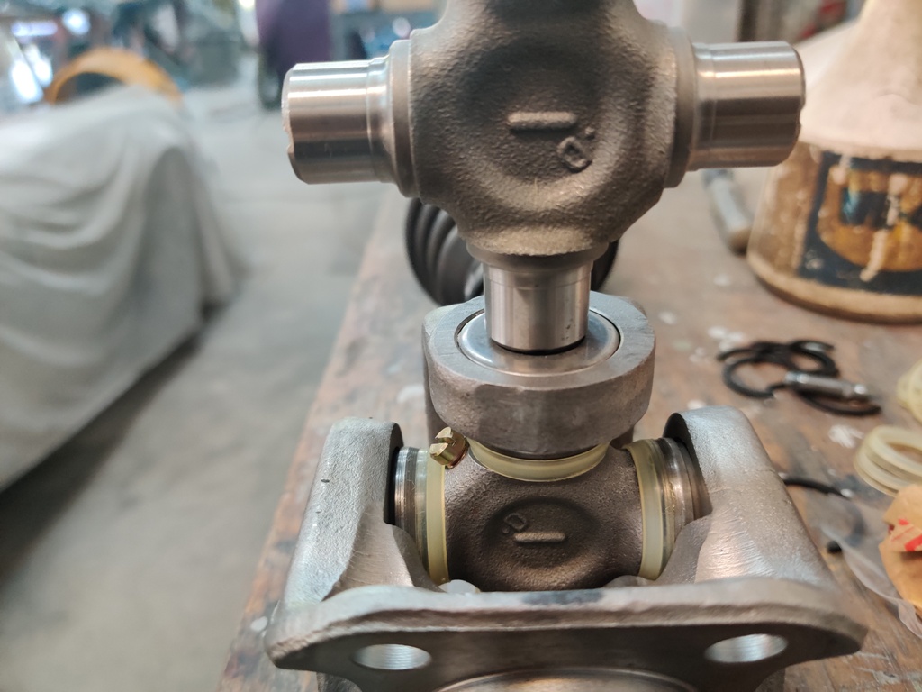
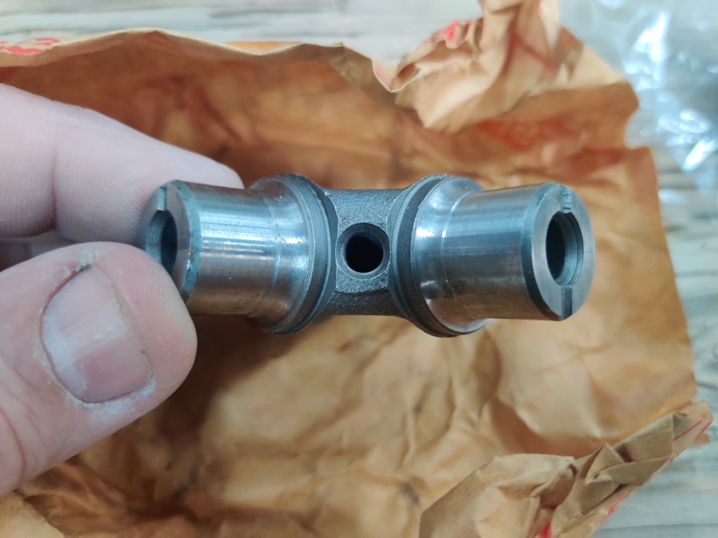
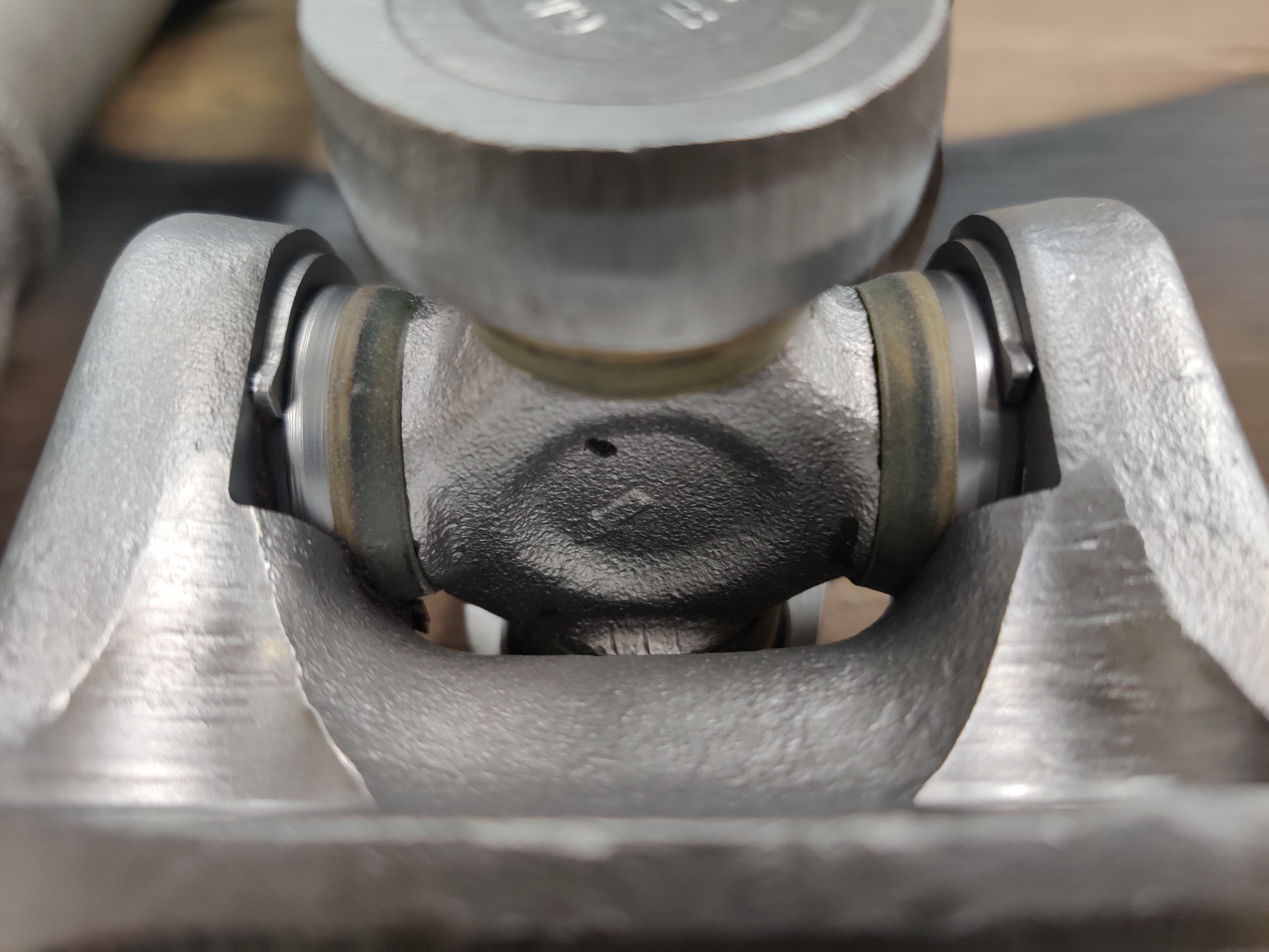
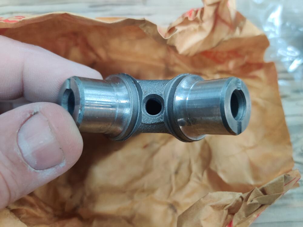
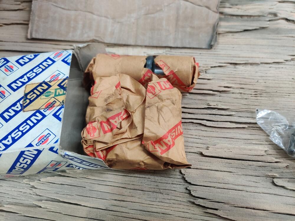
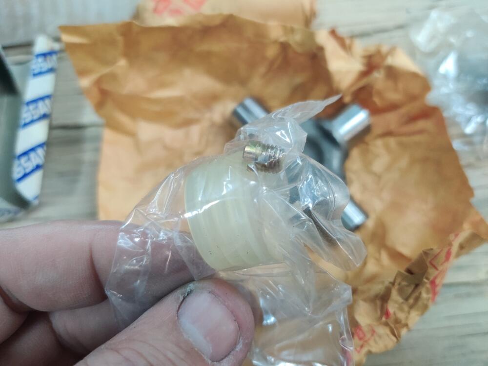
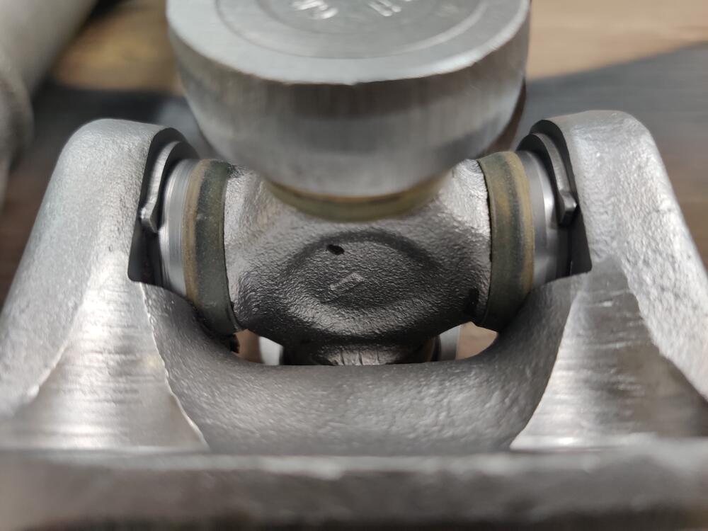
I have started replacing the u-joints the 240Z I am restoring. I think the u-joints I removed are original to car. Can anyone confirm? What tells me they are factory? Well, there is a fair amount of evidence from looking at the history of the car, the receipts, and the amount of crusted dirt that was on the u-joints. Basically, the car appears to have about 120k miles on it - a notable amount of crust that I had to remove from the u-joint spider, and the snap rings I removed look just like the ones that came with the NOS u-joints (different from all the aftermarket u-joint snap rings I have ever seen). Anyway, on to some selected text from the factory shop manual and some questions. When looking at the RA chapter from the workshop manual (Rear Axle & Rear Suspension)... First, a little bit of levity - per the manual, did you know that "The drive shaft should be disassembled only when lubricating the ball spline" and further "The lubrication is required every 50,0000 km (30,000 miles)"? Bet you didn't, and you'd better get on that. 😛 Setting that aside, oddly, when addressing replacing the universal joints from the axles, the factory workshop manual refers the reader to the "instructions described in the paragraph covering the propeller shaft if faulty condition is detected". So, I turned to that section of the manual. Unfortunately, the propeller shaft (drive shaft) is a bit different than the axles. So, I am left with some ambiguity and therefore, some questions. Let's start with "Before disassembling the journal, verify the component alignment and relationship so that the yoke direction and snap ring thickness are not changed (when the yoke direction and/or snap ring thickness is changed, the tube and journal center alignment is deviated and the propeller shaft is unbalanced) because the journal is balanced as an assembly. It is desired not to disassemble the propeller shaft so that the alignment is not unbalanced." So, translation? Don't take it apart if it can be avoided. Of course, I have already taken the u joints out and found them to be in need of replacement. I have only disassembled one axle - just the u-joints removed so far. And before I did so, I marked everything so as to keep all parts in their factory assembled orientation. Axle yokes, axle, u joints, u joint snap rings... all laid out per their assembled orientation. Now, a few words about the new oem u-joints. These are new old stock. Note that the D and "dot" seem to be indicating where the u-joint is drilled and tapped for a grease fitting (the package includes a screw plug): These original equipment u-joints come with an assortment of snap rings: Note the colors painted on the edges. There appear to be 6 sets of two. The factory workshop manual only provides info for 4 colors, and those are for the driveshaft u-joints, which are different than the axle u-joint snap rings. Those for the driveshaft are measurably thicker, varying from 2.00 to 2.06 mm (.0787 to .0811 inches). I measured the snap rings that came with the axle u-joints. Generally speaking, they range from .059" to .066". So.... One of my more important questions is, what snap rings should I use? Turning again to what is written in the workshop manual: "Reassembly" "The component parts are reassembled in reverse sequence of disassembly. When reassembling, select and use a proper snap ring out of the following types (four types) so that the journal moves under the following conditions: 1. Bending resistance of the journal unit is less than 1- kg-cm (9 in-lb). 2. When a yoke in one side is set stationary and a load of 10 kg (22 lbs) is applied to the other yoke alternately, the relative displacement of the yoke toward the axial direction is less than 0.02 mm (0.0008 in)." The four types, by the way, appear to be the four colors for the driveshaft u-joint. For the axle u-joint, it looks like we have 6 types (colors). My measurements of the supplied 6, again ranging from .059" to .066" roughly corresponded to two of each of the following: .059", .060", .061", .063", .065", and .066". Separately, the snap rings I removed from the old u-joint are mostly, to my measurement, .062". Interesting. Looking again at number 2 above, I think what I am supposed to do is use two snap rings of the same size at opposing journal locations. For example, I could install the old ones - .062" at each of the four journal locations, or perhaps two .062" opposite each other, along with two .061" opposite each other. Next, I should attempt to use a pressure of 22 lbs against the "other yoke" and check for axial movement (which would occur if the spider of the u-joint were to sink further into the u-joint cap. Success in determining the correct snap ring is achieved when "the relative displacement of the yoke toward the axial direction is less than 0.02 mm (0.0008 in). Right? Thoughts? I've been looking through all of this this evening trying to figure it out. I wonder... how many people install new u-joints and don't get the movement in the axial direction sufficiently tight? If axial movement is "too much", it could cause wild vibration. Lastly, I wonder if the grease fitting location on the u-joint matters in any way? So far, I have one new u-joint installed. Should I install the second one on the axle as pictured - with its grease fitting location 180 degrees opposite, in this orientation?


-
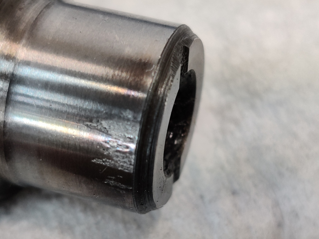
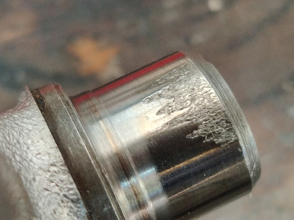
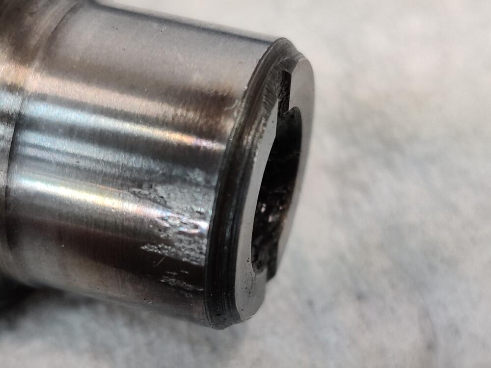
Well, I won't be attempting to drill them because I found a small amount of pitting on the surface of the journals when I took the u-joints out to inspect them. Time to replace them. Inner u-joint... and outer u-joint for one axle:
-
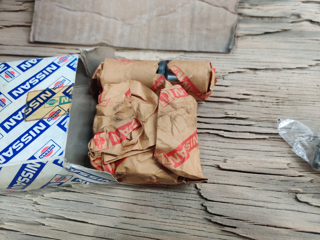
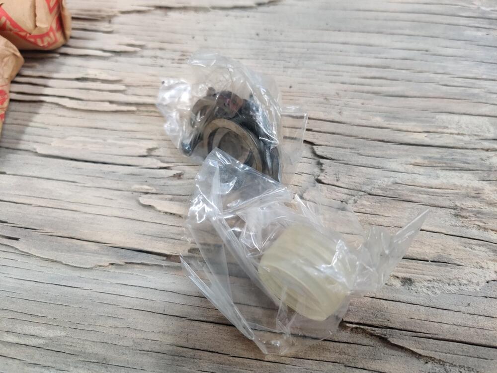
I removed and examined the u-joints from one axle. Even though they felt very nice, when I took them apart, I found some damage. First pic - outer joint, second pic, inner joint, and third pic - oem new in box joint: The new, oem joint is pre-drilled for a grease fitting but comes with a screw/cap, and retaining clips with different colors painted on their sides. They differ in thickness, with 3 or 4 groups of four clips. I think 12 total are included. I wonder if this casting mark (the I) is important (first pic)? The "D" location corresponds to the drilled hole for the grease fitting. I had two oem nos joints in my stash. Since both of the joints in the one axle I took apart had damage, I went ahead with ordering two more. I found some nos oem of the same part number on eBay for about $50 each. I need to review the what the factory shop manual says about replacing these u-joints to make sure I am not missing something important about the replacement process.


-
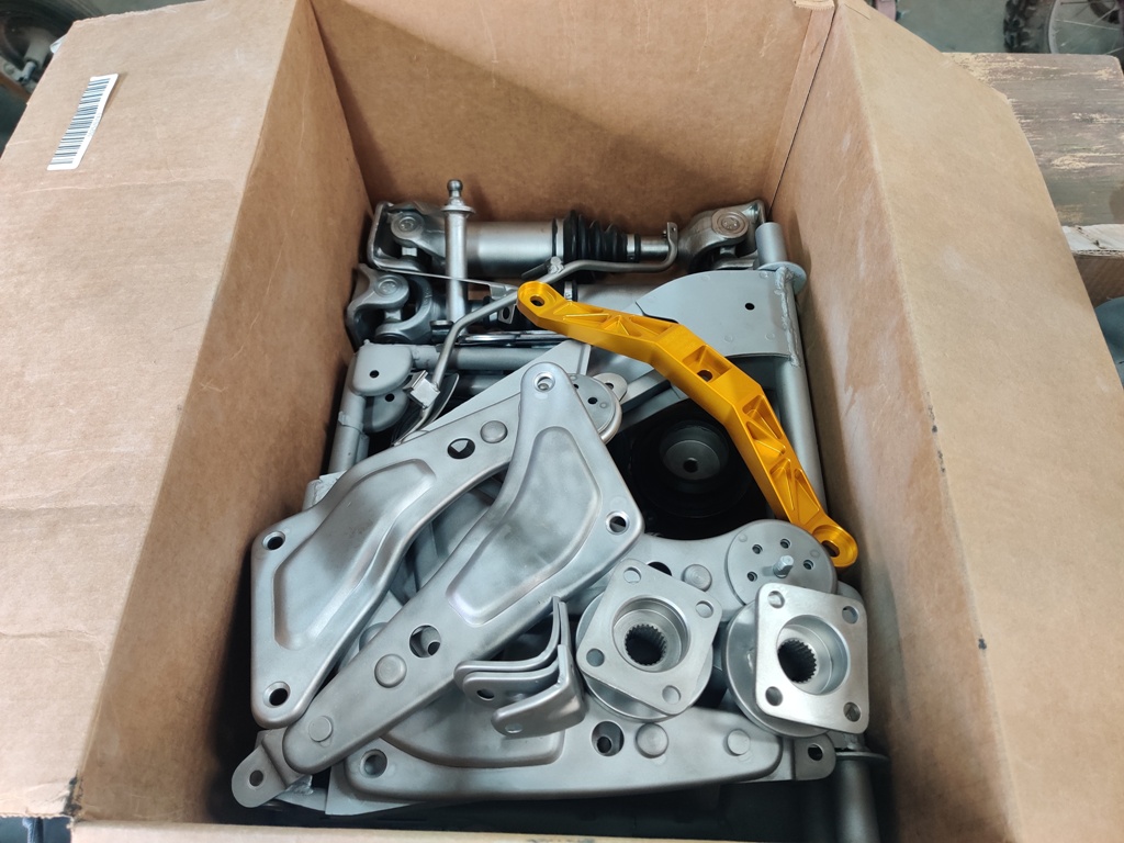
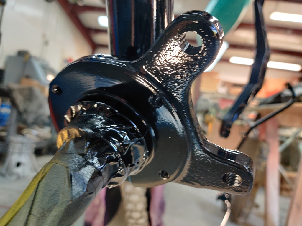
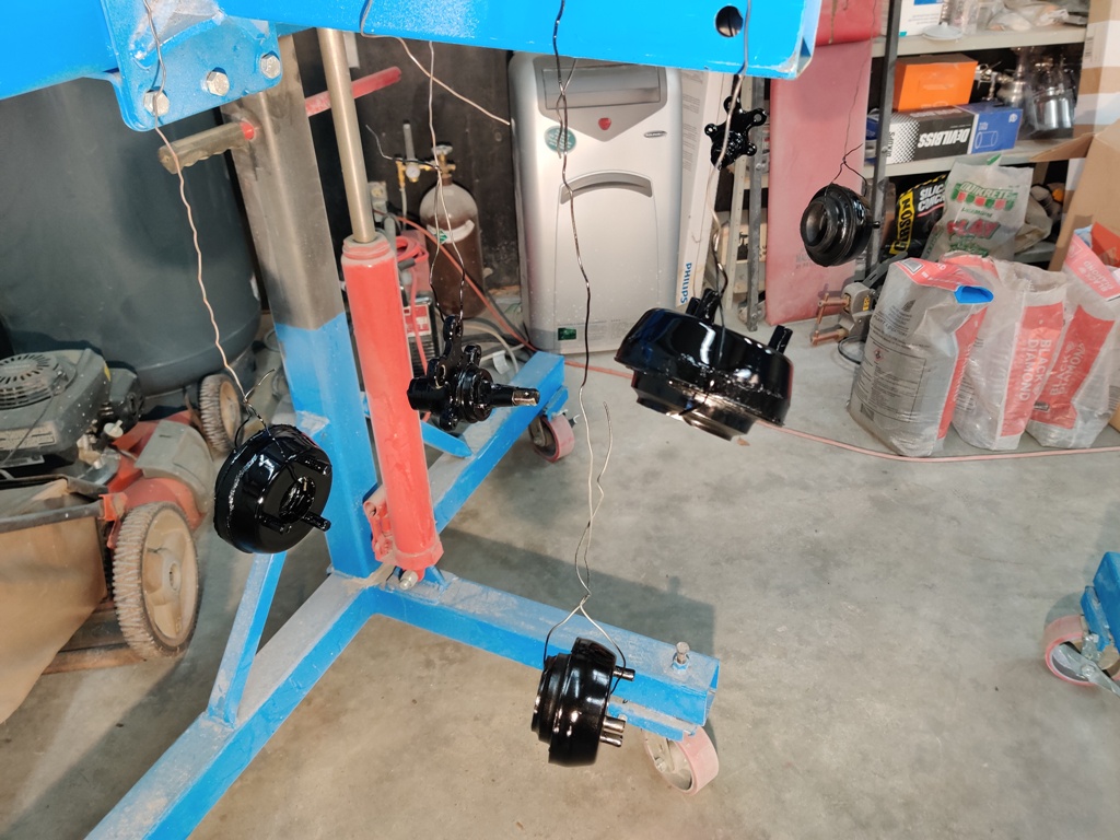
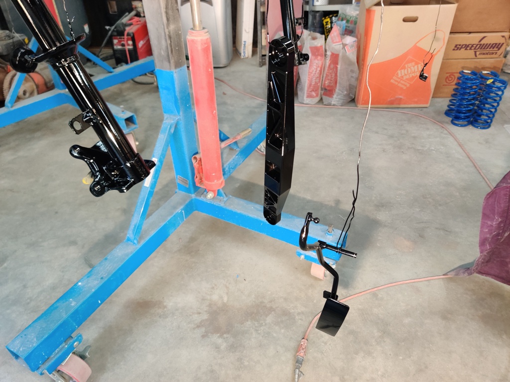
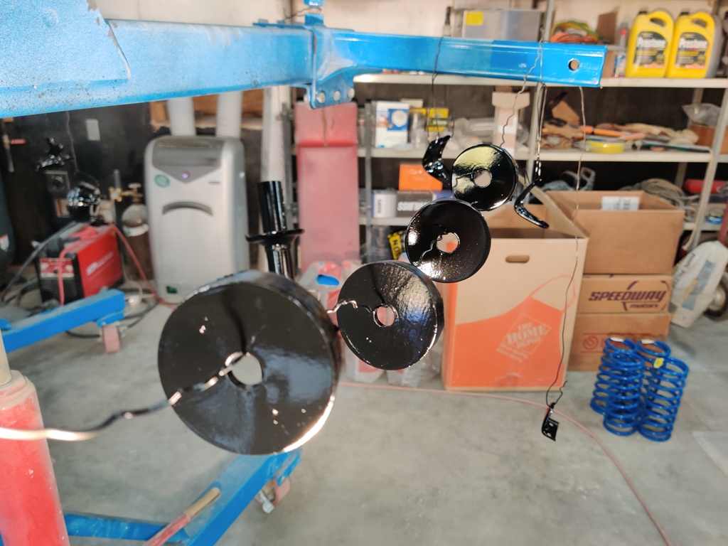
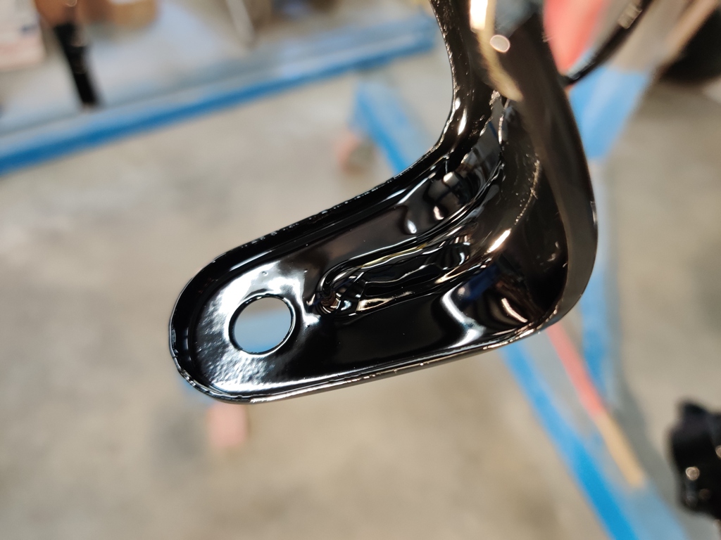
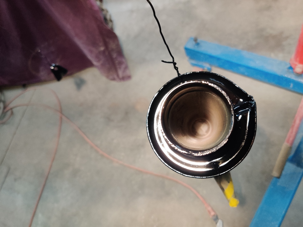
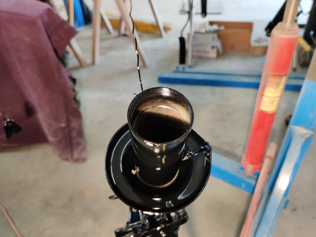
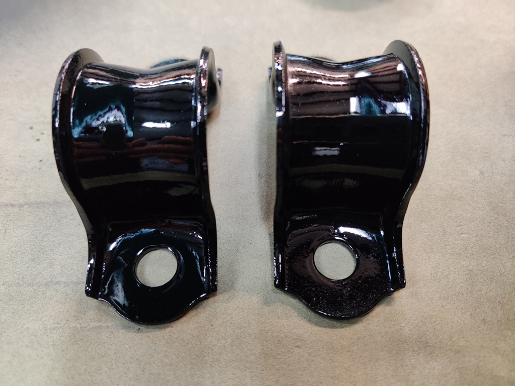
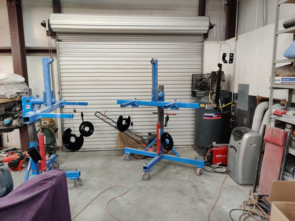
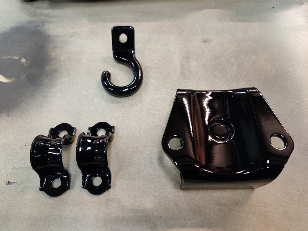
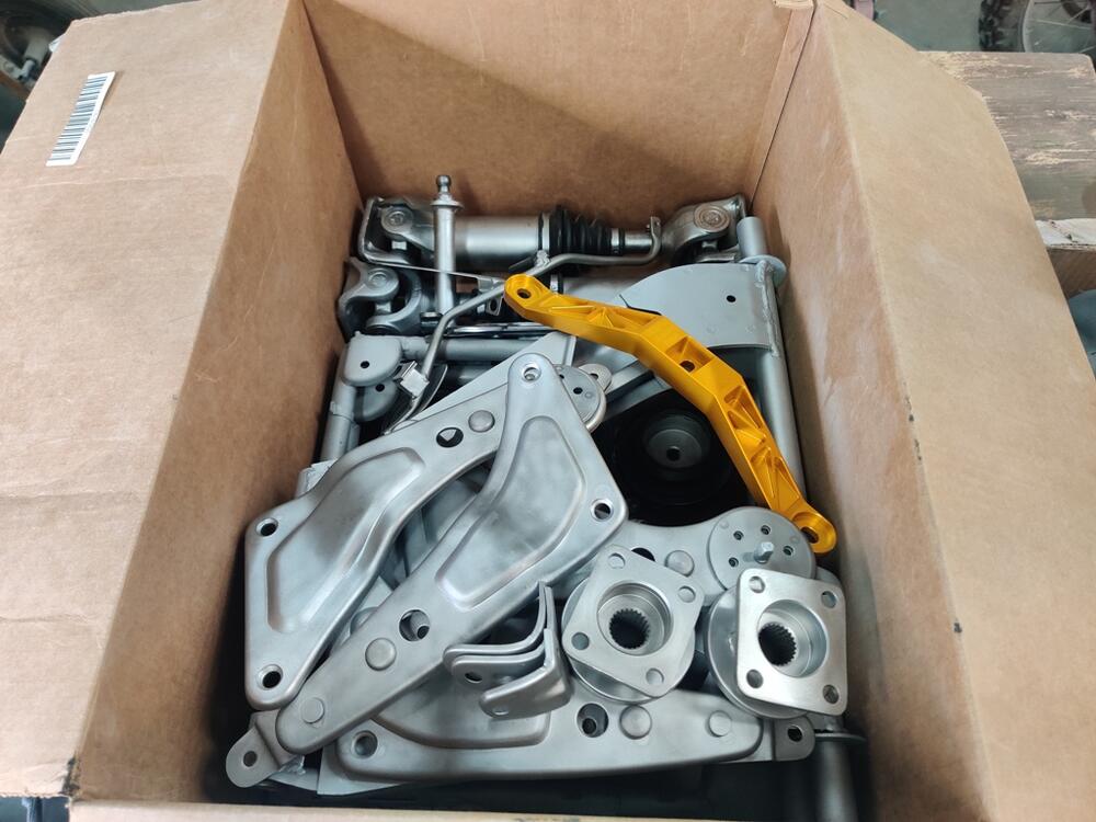
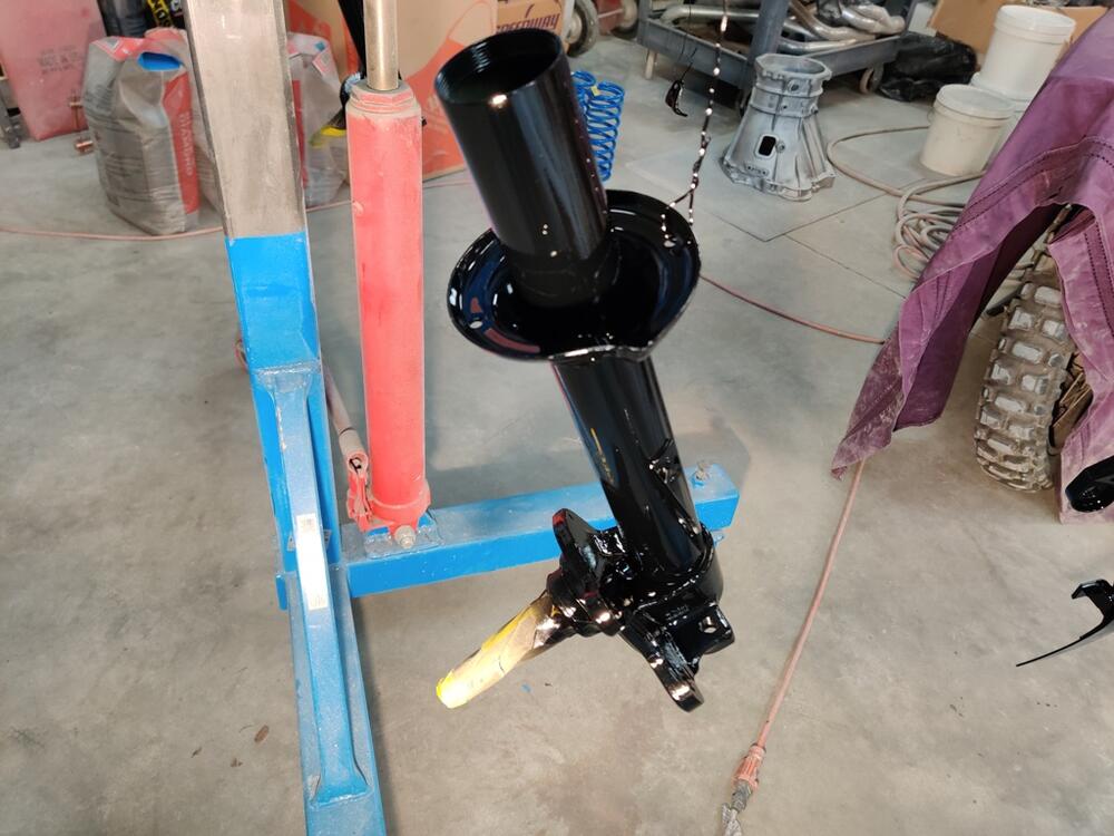
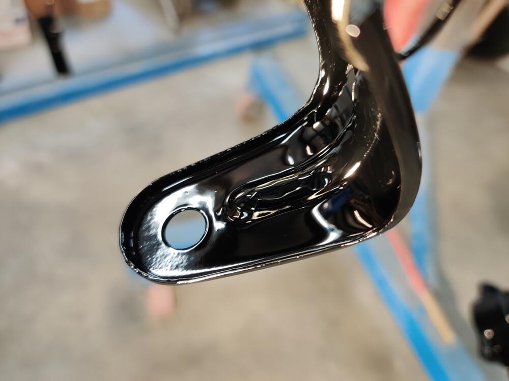
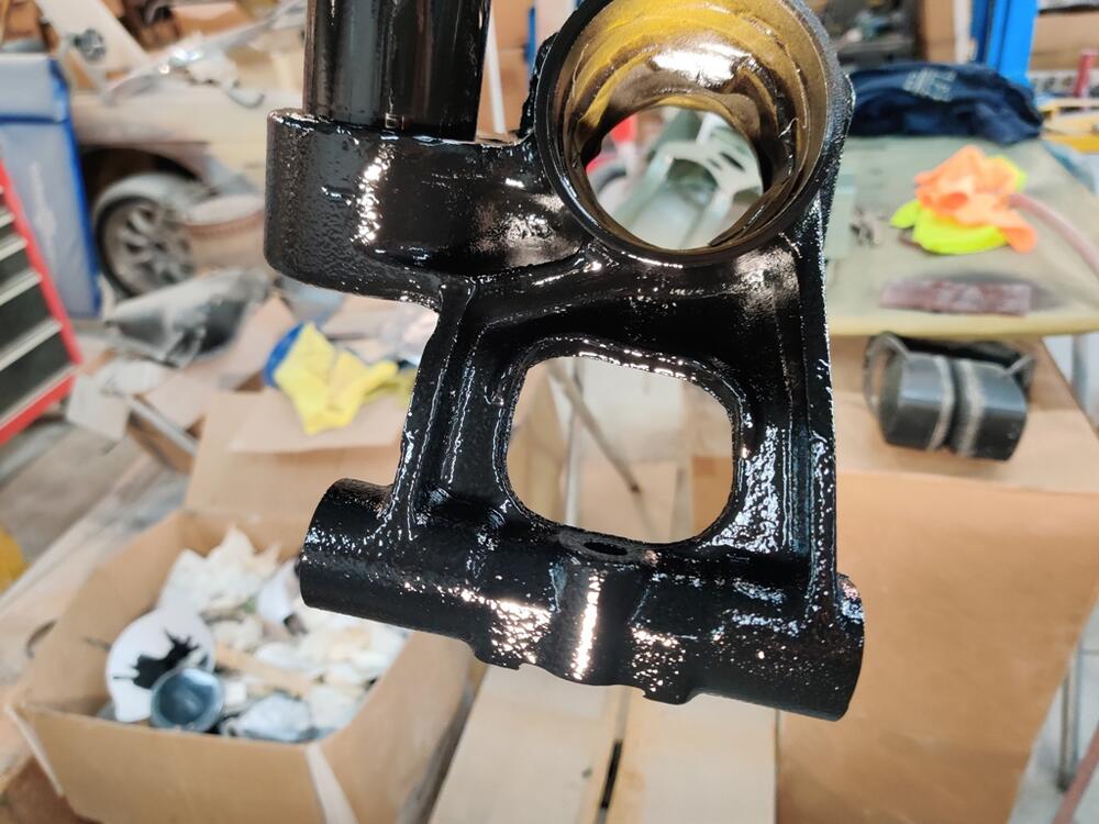
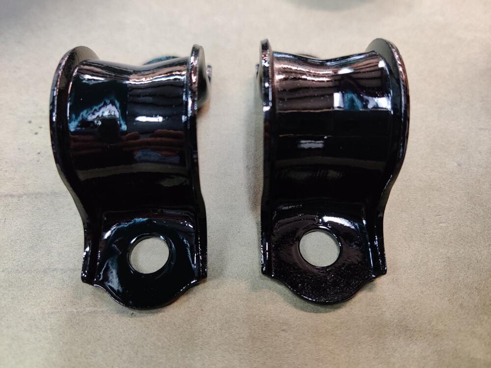
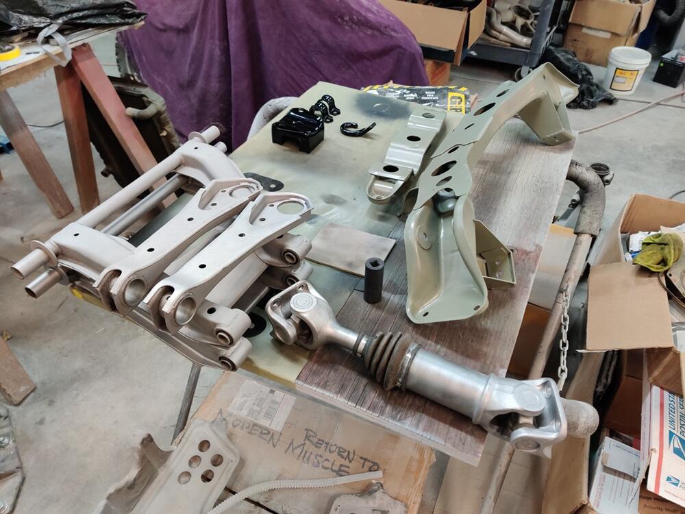
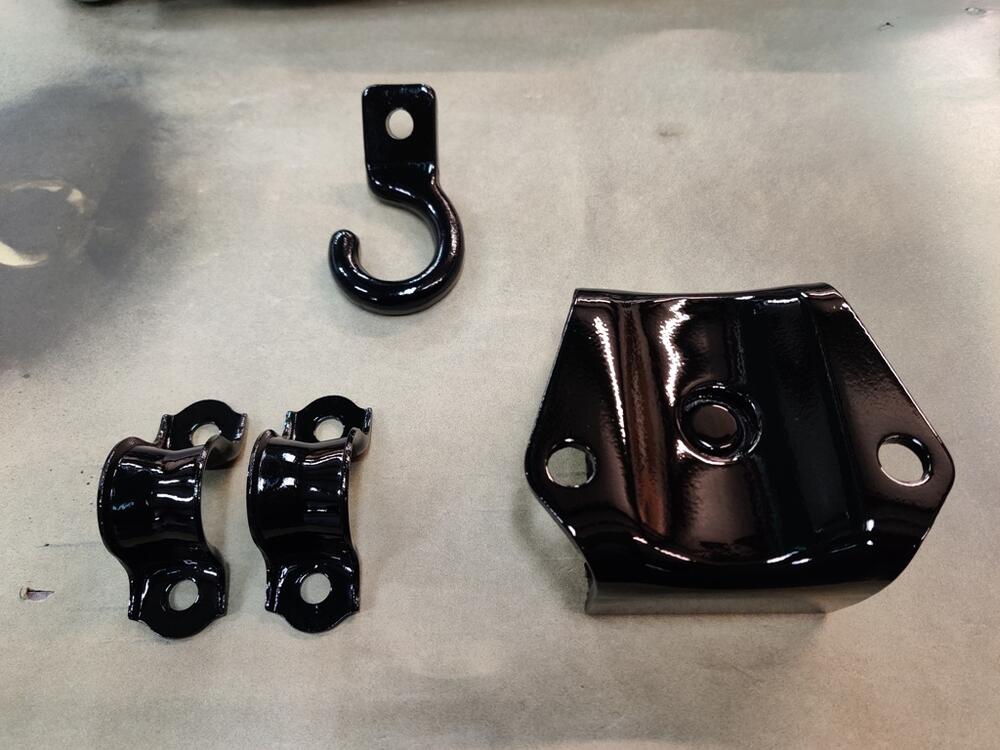
I have made some more progress with bead blasting (after coal slag blasting), and priming and then painting of black parts. I am really pleased with how these are turning out. First pic: Gold in a sea of silver - that is the T3 transmission crossmember for installing the 240SX transmission. Second pic shows brake hose bracket repaired on one of the front struts. Third pic - the rotisserie makes for a nice place to hang parts for painting. Front strut: T3 crossmember, gas pedal, rear mustache mount washers, dash vent bracket: Other front strut: Rear strut: Other rear strut: I am about 2/3rds of the way through the black parts. The nice thing about getting these done is that I can move on to some more of the assembly part of this process. No word from the painter about work begun on the car. Still waiting for paint sample cards.


-
Where is your neck of the woods out of curiosity? I use my press quite a bit, so getting a 20T to replace my 12T seems like a good idea at this point.
-
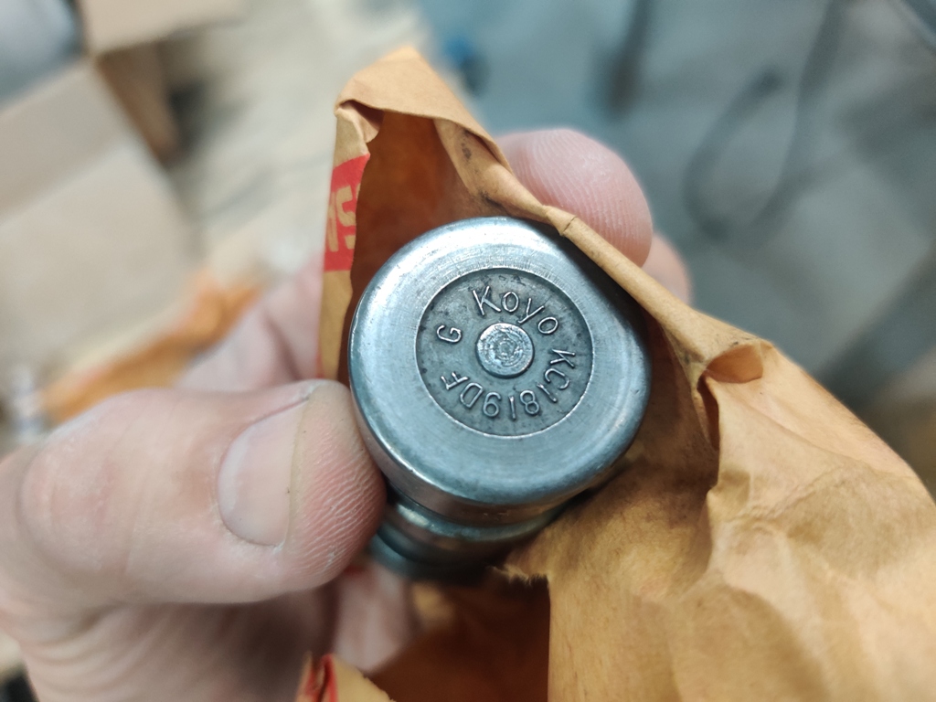
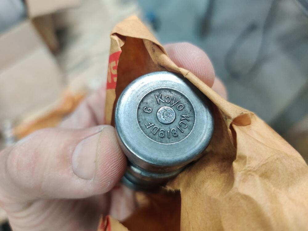
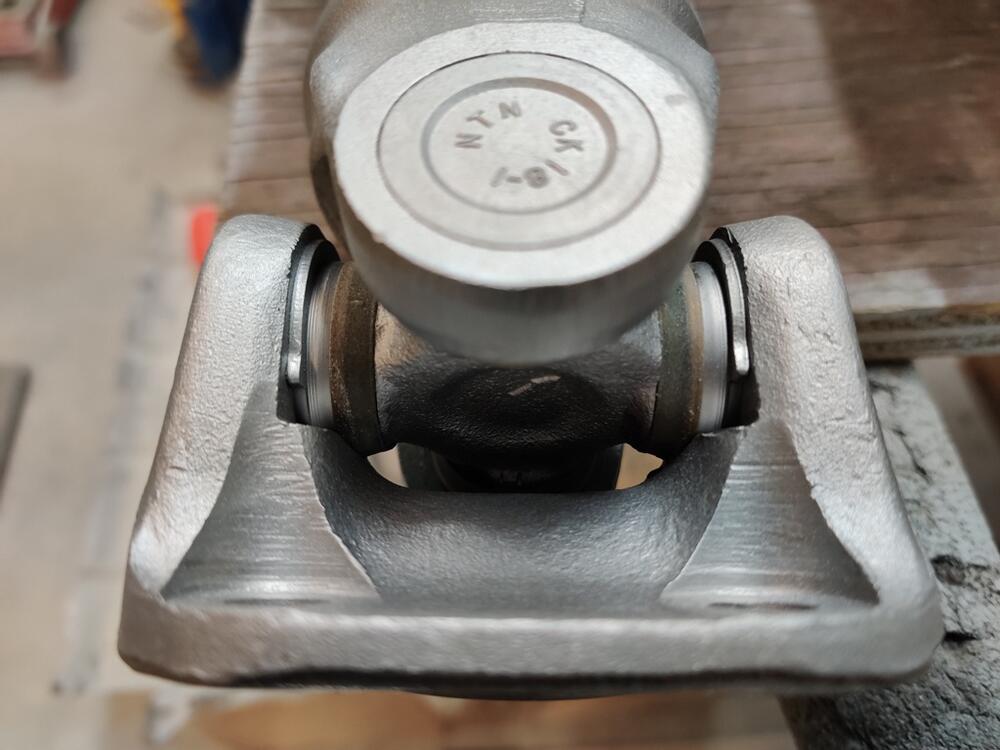
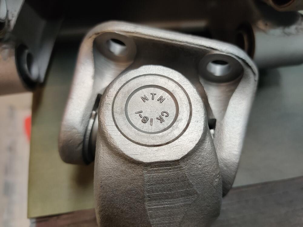
I removed the u-joints from one of my axles tonight. I can't see any beads that got past the seals, but I will be cleaning them regardless. Took a look at that with the axle I worked on tonight and the arrows are at 90 degrees - not 180. I'd like to know if these are replacements or original. I have since a two different brands that are original so far: "Torrington" and Koyo". No idea if these N T N are also OEM.
-
I located a couple of NOS driveshaft u-joints in my "boxes of stuff" tonight. I was curious if they were drilled for grease fittings. I found out that they are. Interestingly, if you look at the corners and markings, you see they are similar to the ones on my shafts. However, instead of an arrow, there is a D on the corner that has a flatter surface than the other corners: Additionally, the brand is Koyo for the two I have in boxes, and not grease fitting was included, but instead a plug was. I still suspect that I could drill and then tap the existing u joints for a grease fitting. I will need to decide how to proceed before I prime and paint the axles. They were painted after assembly at the factory (paint over rubber boots and bands as well), and I am thinking about replicating that. I am leaning toward taking the u-joints out and apart and cleaning them and repacking them with grease. I may attempt to drill and tap and install grease fittings into them.


-
I am back from a week of vacation which consisted mainly of relaxation and recuperation. I located the manual and receipt for my press. It is a 12 ton capacity press. I purchased it in 1999 for $127 including shipping. The bottle jack stopped working a year or so ago, and with a new bottle jack (12 ton) only $30 something with shipping, it wasn't worth my time to tear it apart. Hate that. One of the few times I convinced myself to just chuck it. I did open it and look for anything obvious first. 😉 Anyway, I was reaching the limit of the bottle jack with these rear control arm bushings. The handle went kind of "soft". And I was using a propane torch simultaneously to add a bit of heat to the portion of the control arm that the bushing presses into, admittedly I did not add a lot of heat though. The 12 ton press served most of my needs... but these bushings surprised me. I didn't expect them to be this tight. But, it looks like 20T has worked, so I am thinking I will go that way.
-
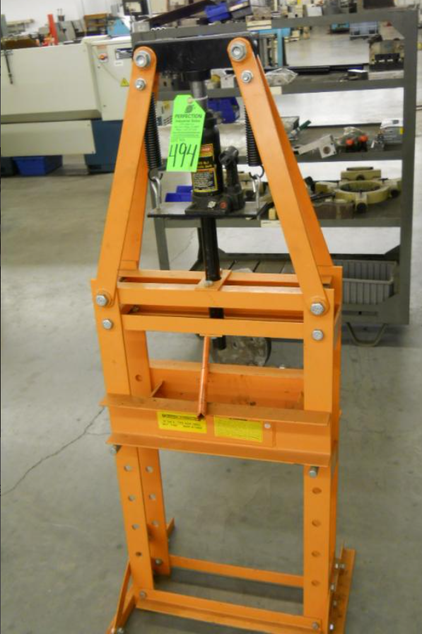
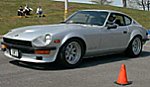
My press is only 12T, I think, from harbor freight. Looks just like this: Based on everyone's input, it sounds like I would have success with a 20 ton press. I found this for $68.50 and free shipping. https://strictlymot.com/products/20-ton-hydraulic-shop-press?currency=USD&variant_sku_code=2777136-0-0-0-0-0-0&gclid=CjwKCAjwiOCgBhAgEiwAjv5whLBTtoAkp7L5HAnW0p-SVQ3SGIv9FU6RxWIz6PNaUjKpF8_iqv3SLRoCxPsQAvD_BwE Sounds like too good of a deal to be true - and I'd be risking personal info if I tried buying it!

-
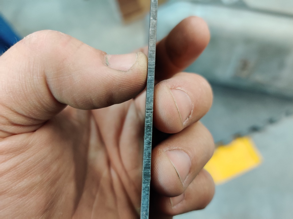
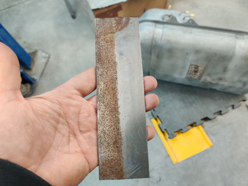
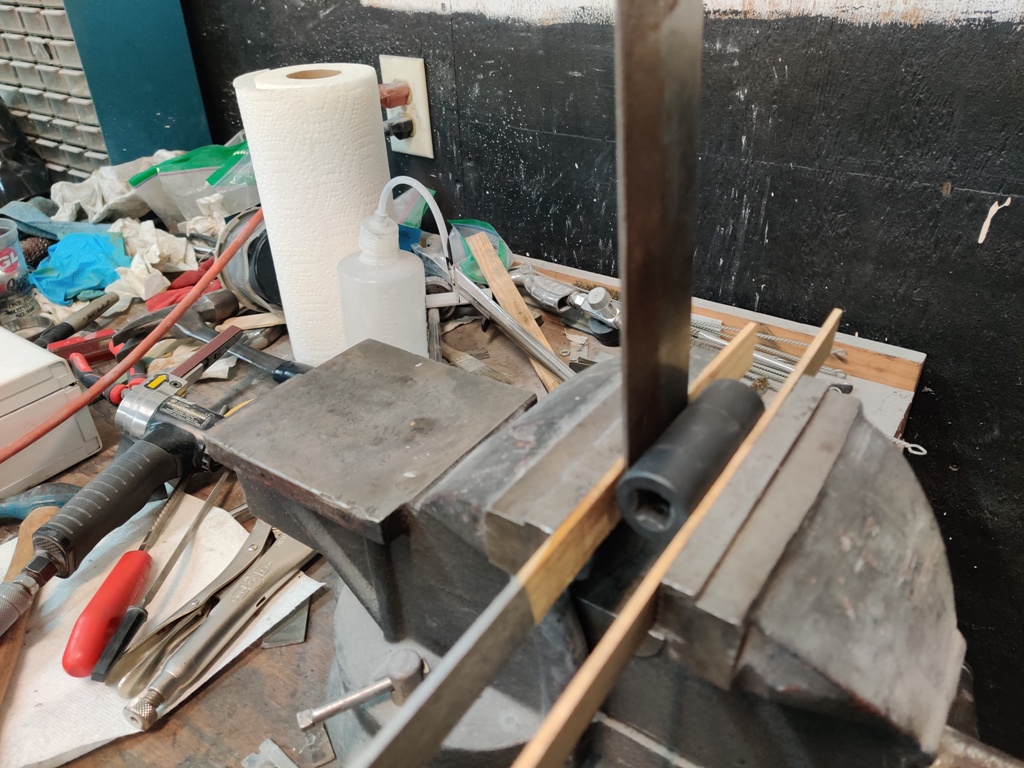
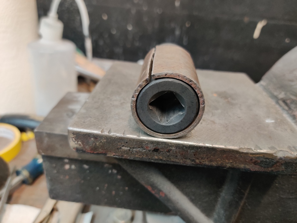
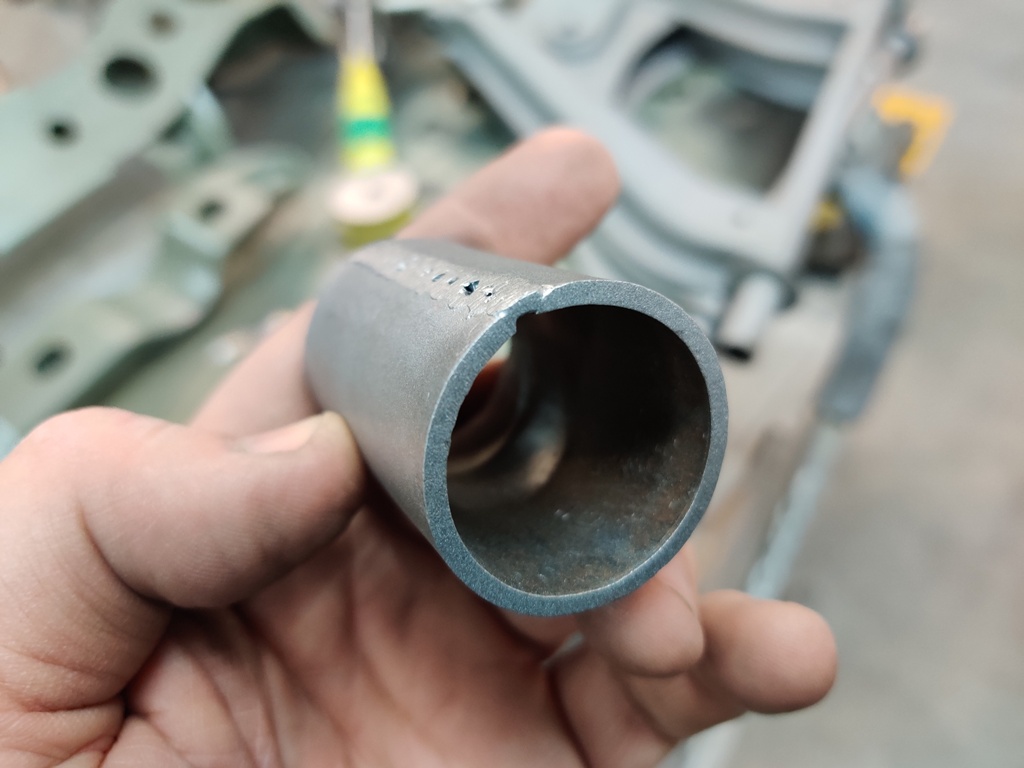
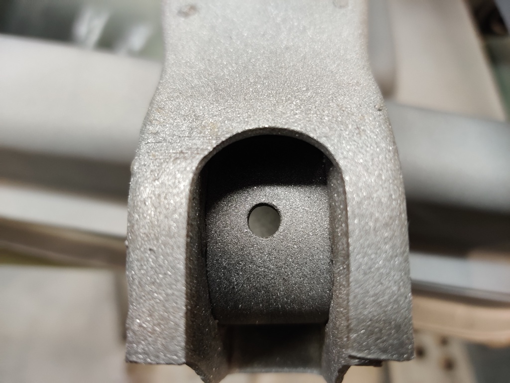
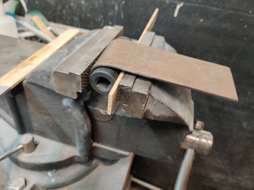
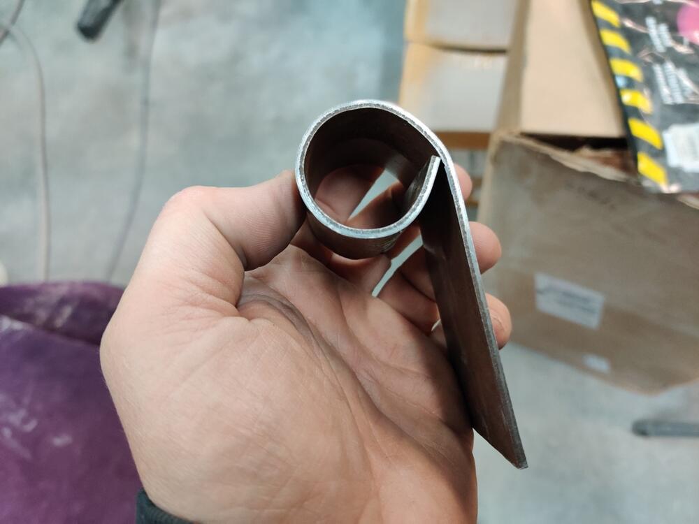
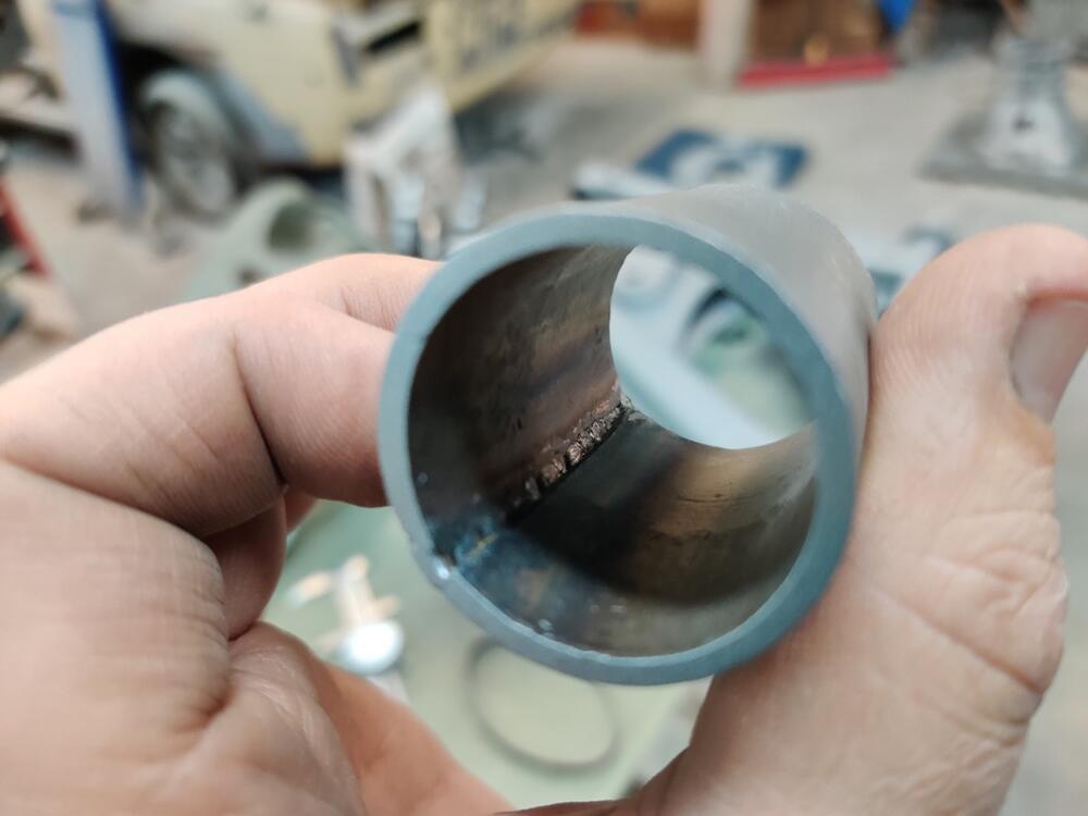
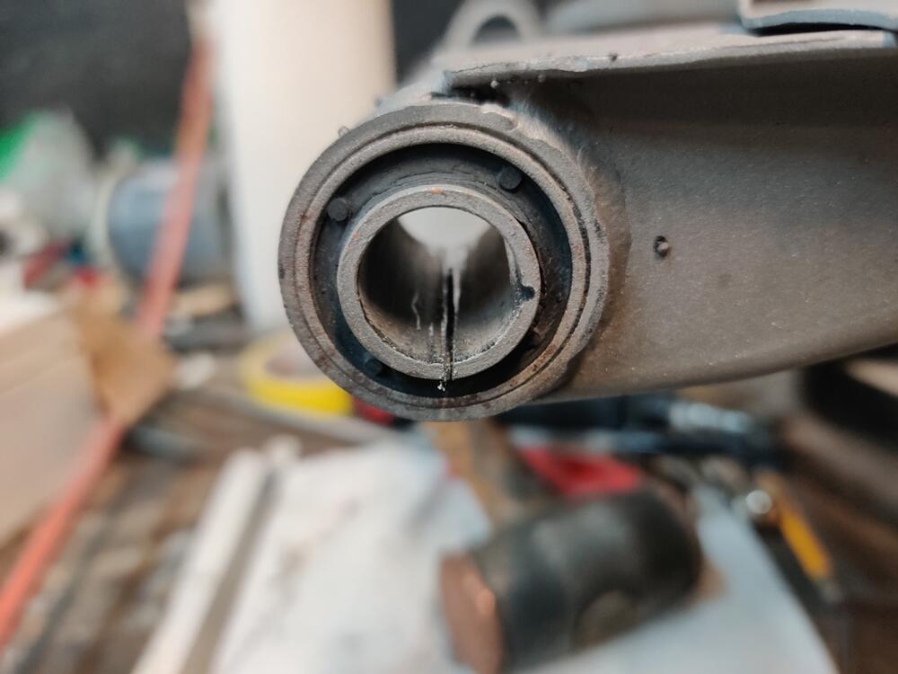
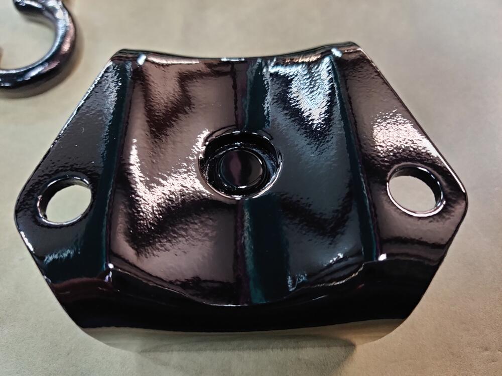
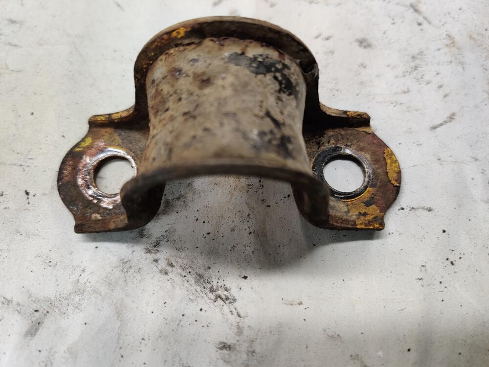
I decided in the few hours I had to work on the car today, I would make a pipe section for pressing the rear control arm bushings out and remove those. I cut a piece off of my .125 sheet that was suitably wide enough to accommodate the full depth of the bushing when pressed out of the arm, and began bending it. Using the vise, and an impact socket, I continued bending until it wrapped around the socket. Then I cut it to length and hammer formed it around the socket: I then welded the seam, dressed the weld with my hand held belt sander, and the ends with my bench grinder. Then, I bead blasted it to make it look nice. Under an hour and I was at my press with this, the control arms, and various bits to use in pressing the bushings out. Two hours later, I still hadn't gotten even one bushing to budge a millimeter. OD on a new bushing is about 1.185" if I recall correctly. And the impact socket I was using to press the bushing out is 1.182. It's a bit to big, but I should have been able to get a few thousands of an inch, but I got no movement... at... all! I tried going down in size to the next thing I had, another socket that was 1.165". But it wasn't catching enough of the bushing outer sleeve. These bushings have a very thin outer wall sleeve. In frustration, I took a hack saw to one of the bushings and cut through the inner sleeve. But, as soon as I got through it, it collapsed a bit and kept the hack saw blade from moving in and out anymore. What a royal pain in the arse. First time I have been stuck on something in a long time. I am thinking about burning them out. 😠 I will see what others have done first.


-
Spindles are out - I am talking about removing the control arm bushings from the rear suspension arms - what the spindles go through. Thanks anyway though!
-
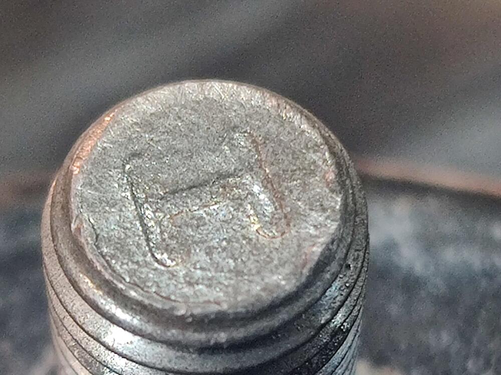
About the rates, Katz posted info that decodes which spring goes on the front left and front right, one page back in this same restoration thread: These after market springs from Suspension Techniques are the same free length and rate for the front, and the same for the rear. Interestingly, the rate for the rear is higher. In my heavily modified Z, I run 250 pounds per inch rate in the front and 375 pounds/in rate in the rear. I had already taped up studs for two out of four of the isolators before I noticed the marks. I'm curious if there are others besides the "I" and "J" on the other two. Playing two soccer games (in the freezing cold) will prevent me from making much more progress on these parts today. I had a thought about removing the bushings from the rear control arms, however. I have flat sheet in .062". I think I will make a round pipe of the right inner diameter. Should take less than 30 min.
-
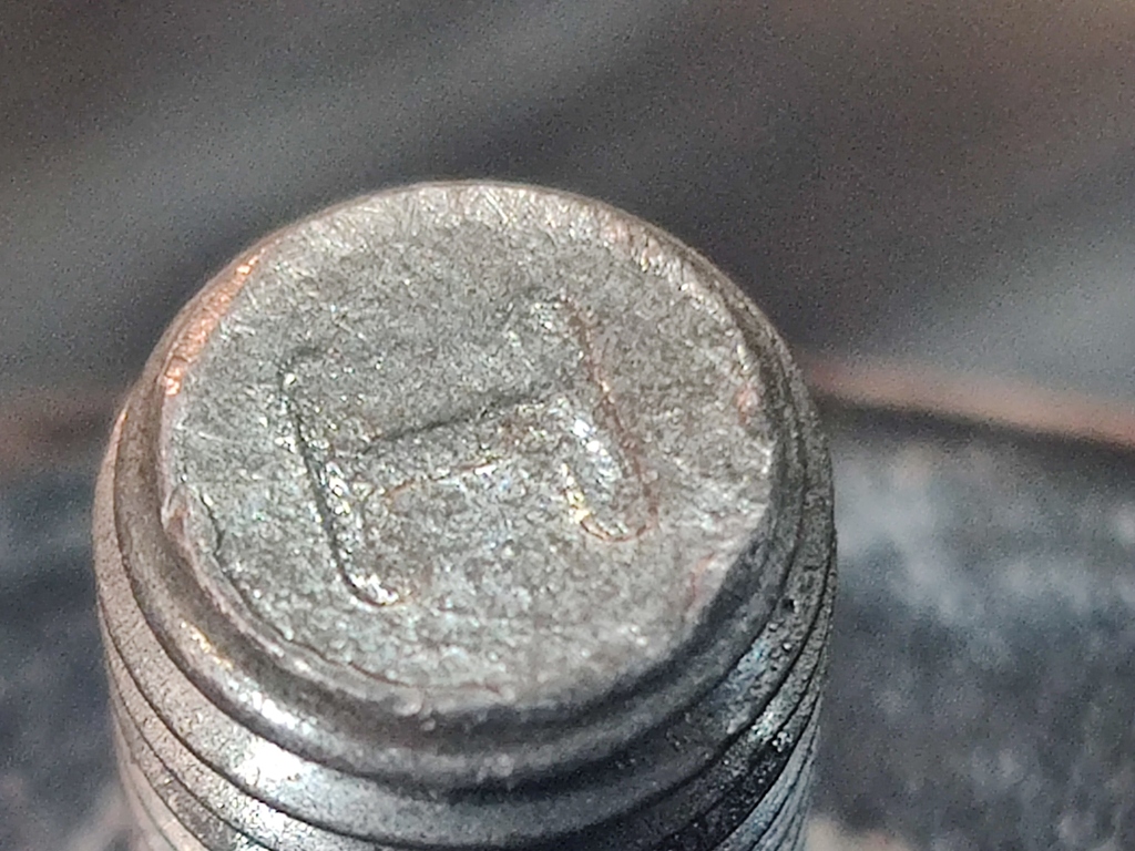
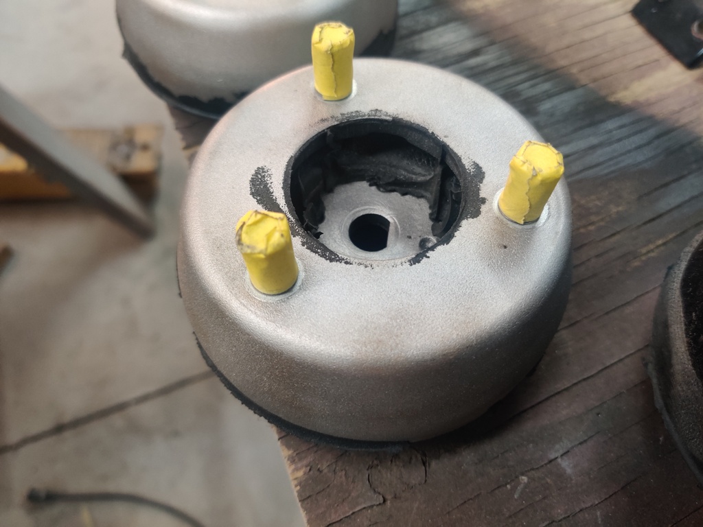
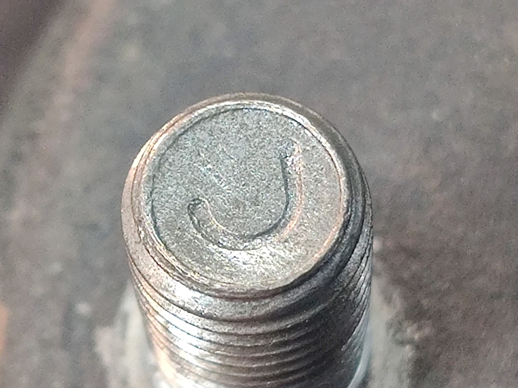
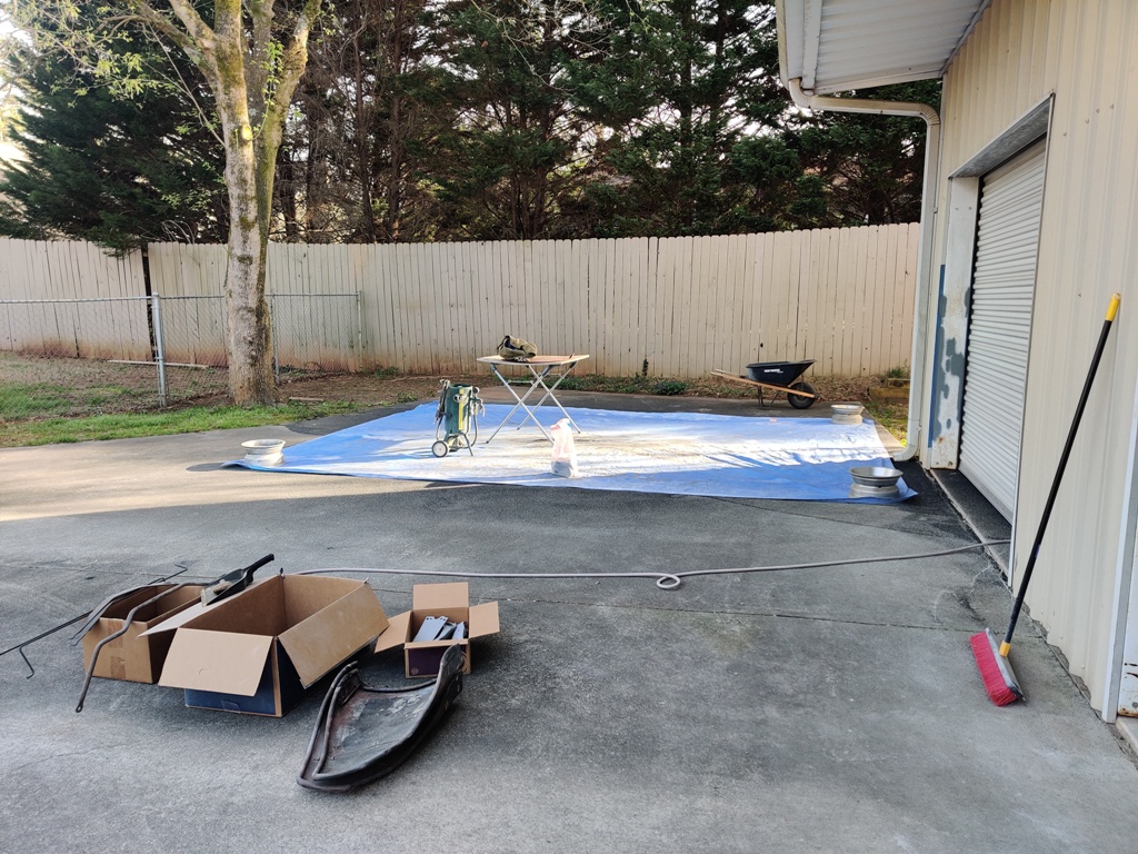
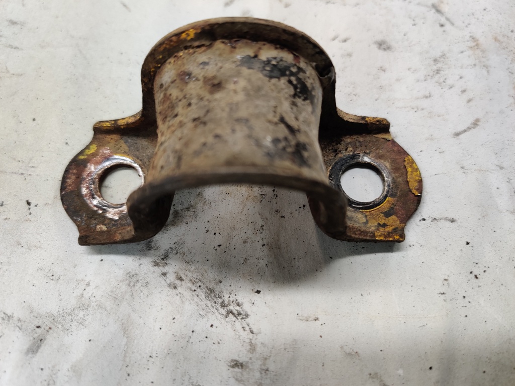
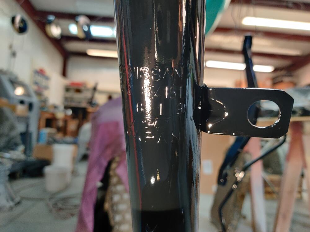
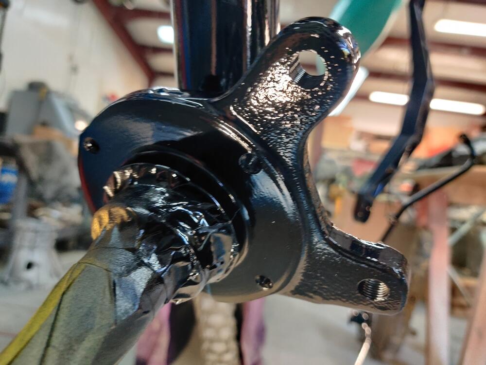
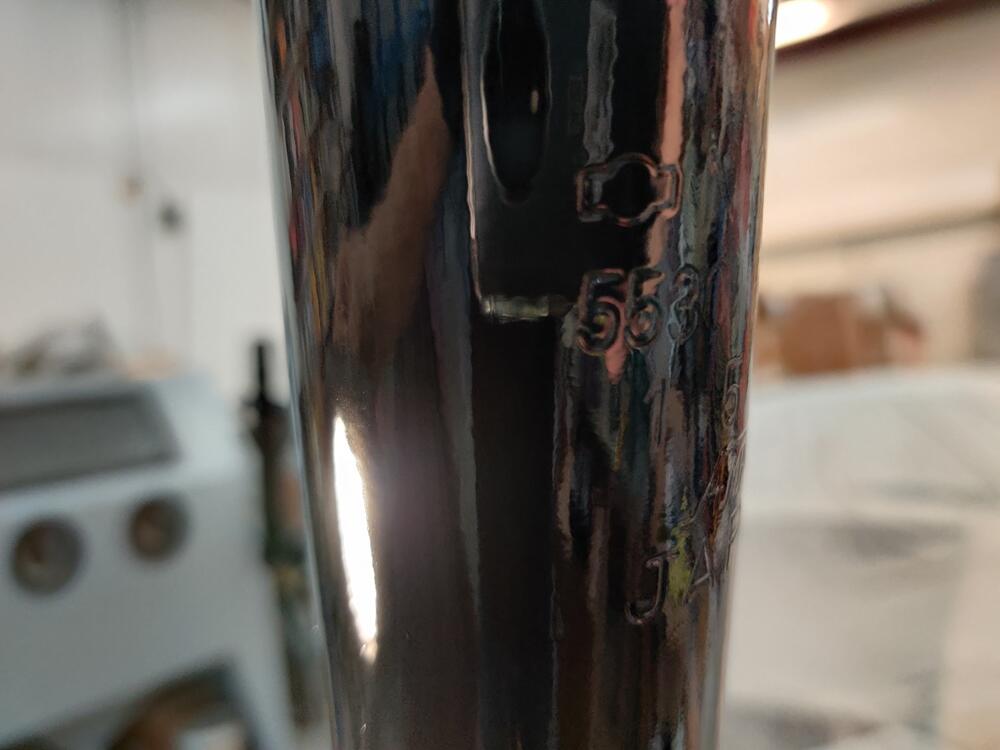
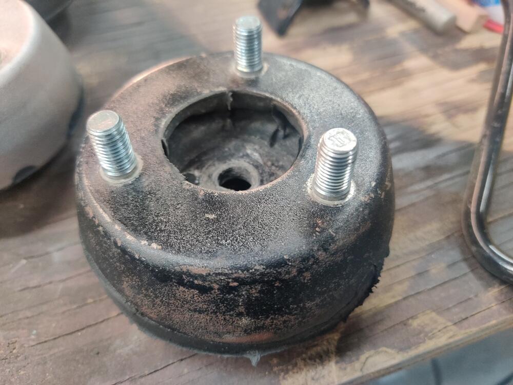
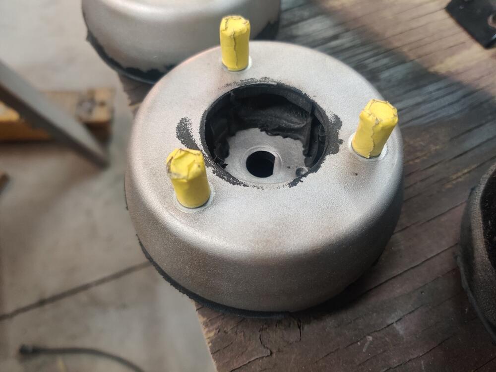
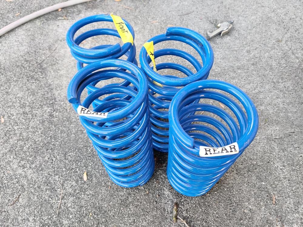
I believe I finished blasting the remainder of my parts today. It was cold... with wind gusts at times, which tried to lift the tarp up. I pushed through though. Next, I'll need to run many of the parts stripped today through the glass bead cabinet to finish them off. I welded metal in to repair the brake hose brackets on the front struts, and finished them with a 13" hand held belt sander. Didn't get pics, but I will and will show later. I forgot to get scrap tube of the right diameter this week to use to press the old bushings out of the rear control arms. I'll have to hold off on priming them until I remove those. Looking at the strut upper mounts, I observe that from the factory, the studs were not painted black: Another thing, which I never noticed before, the studs have letters... or marks pressed into the ends. Does anyone know what these mean? I decided to lightly brush the studs with a brass brush and then tape them off before putting them in the glass bead cabinet. I will leave them taped for priming and painting. I was going to strip the powder coated paint off of the Suspension Techniques springs, but I think I have decided against it. I don't like the blue color. But instead of stripping, I think I will scuff them with green Scotch-Brite and paint them black. Wish I could have sprayed primer on all these tonight, but I ran out of time, and the temp is supposed to hit 24 degrees over night. Not ideal. The epoxy primer needs 60 minimum for 8 hours to dry. Hopefully, no surface rust will start forming before I have the time and the right conditions to prime and paint.

-
Found this post about strut stickers: Wonder if there are any reproductions other than these: https://www.zeddsaver.com/products/datsun-240z-strut-decals
-
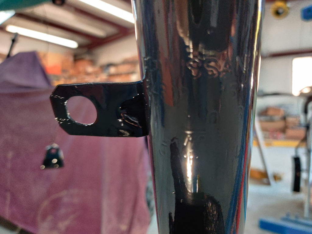
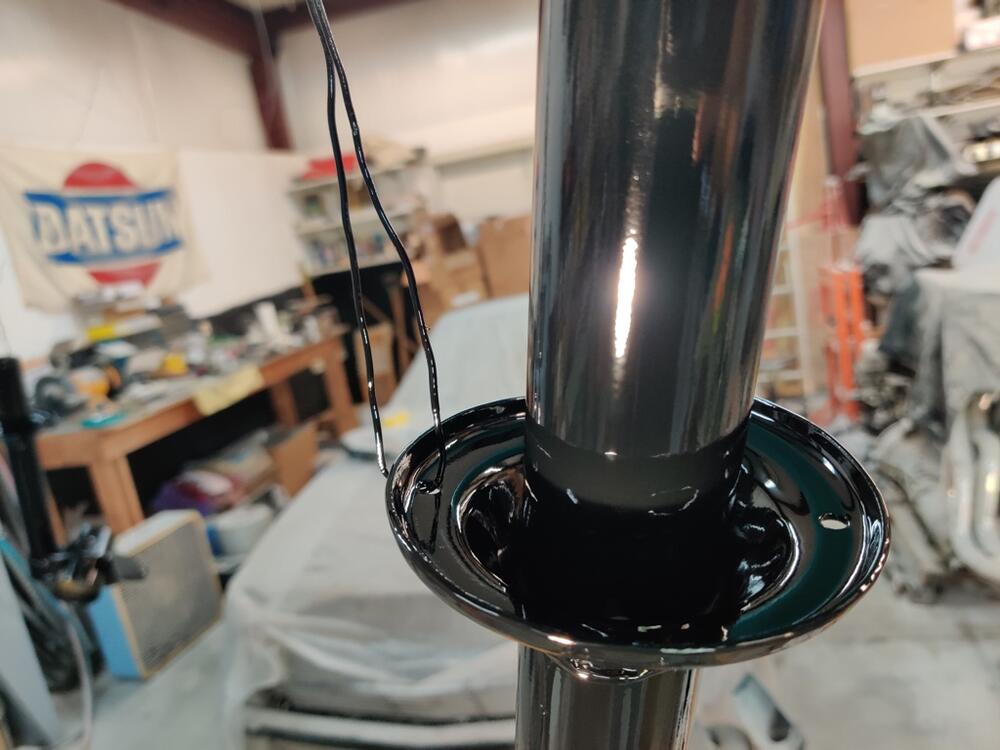
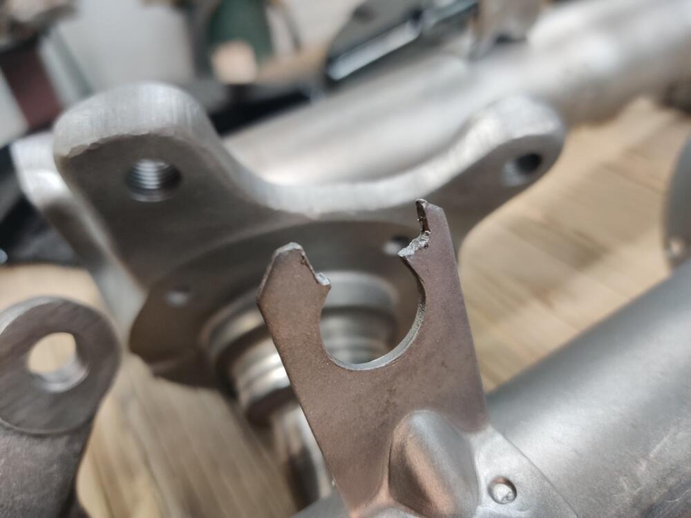
Thanks Charles! I have been re-collecting and straining the used material. I like the idea of using a storage tub. That would keep the media from traveling as far. The weather looks sunny and cold today, good for finishing the stripping of paint and rust from parts. I will attempt to finish blasting of all remaining parts today. The struts have the remnants of what I believe to be a factory sticker: Each of my struts have this same left over sticker residue. It is narrower and longer than these: https://www.zeddsaver.com/products/datsun-240z-strut-decals Anyone know what they are/said originally? The previous owner hacked the brake line support bracket. I'll repair these before painting.

-
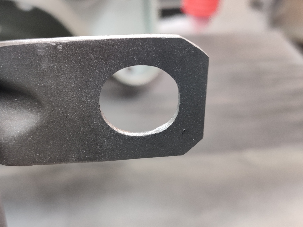
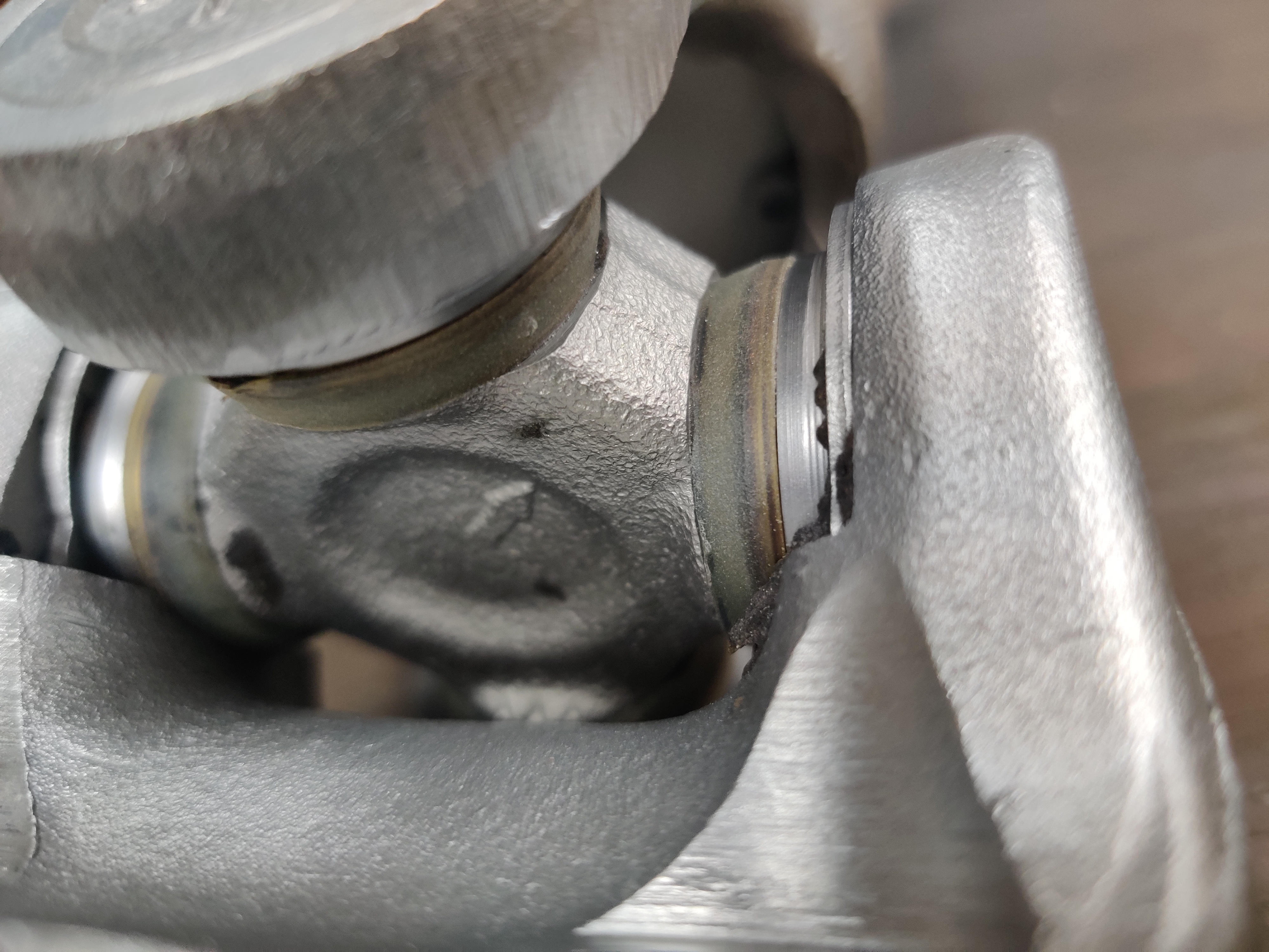
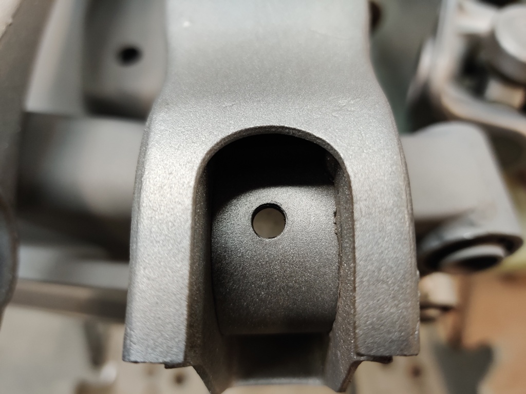
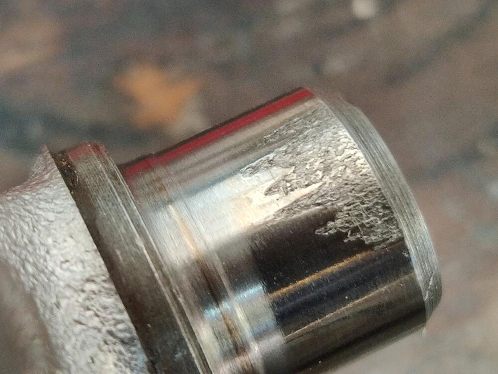
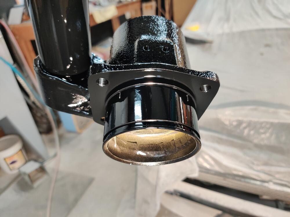
As far as I know, the u-joint is symmetrical. So, I don't think its installation in the axle has to be "clocked" a certain way. But, I don't know for sure. I don't recall seeing grease fittings on any of the factory u-joints on my Datsuns over the years. However, I believe all of the aftermarket ones I have bought in the past did have them. So, the arrow is still a mystery. Regarding getting sand/coal dust under the seals, I don't think it can happen. The seals on the original u-joints are made out of plastic and fit tightly, with no gap for the particles to wedge into. I may still take them apart however, as installation of grease fittings seems worthwhile. I mean, while I have them off the car and stripped of paint, it is only a small (relative) amount of work to disassemble them and put fresh grease. I may drill and tap the u-joints for grease fittings as well.
-
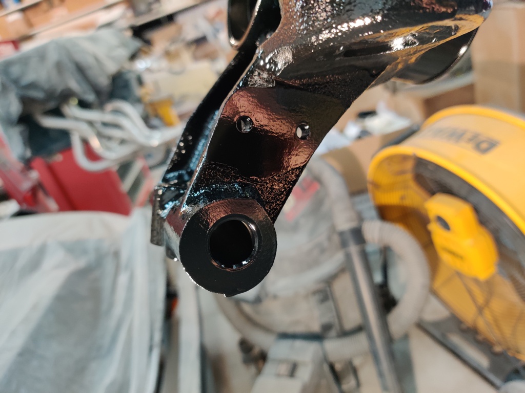
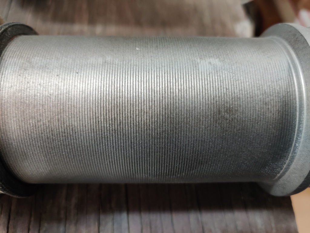
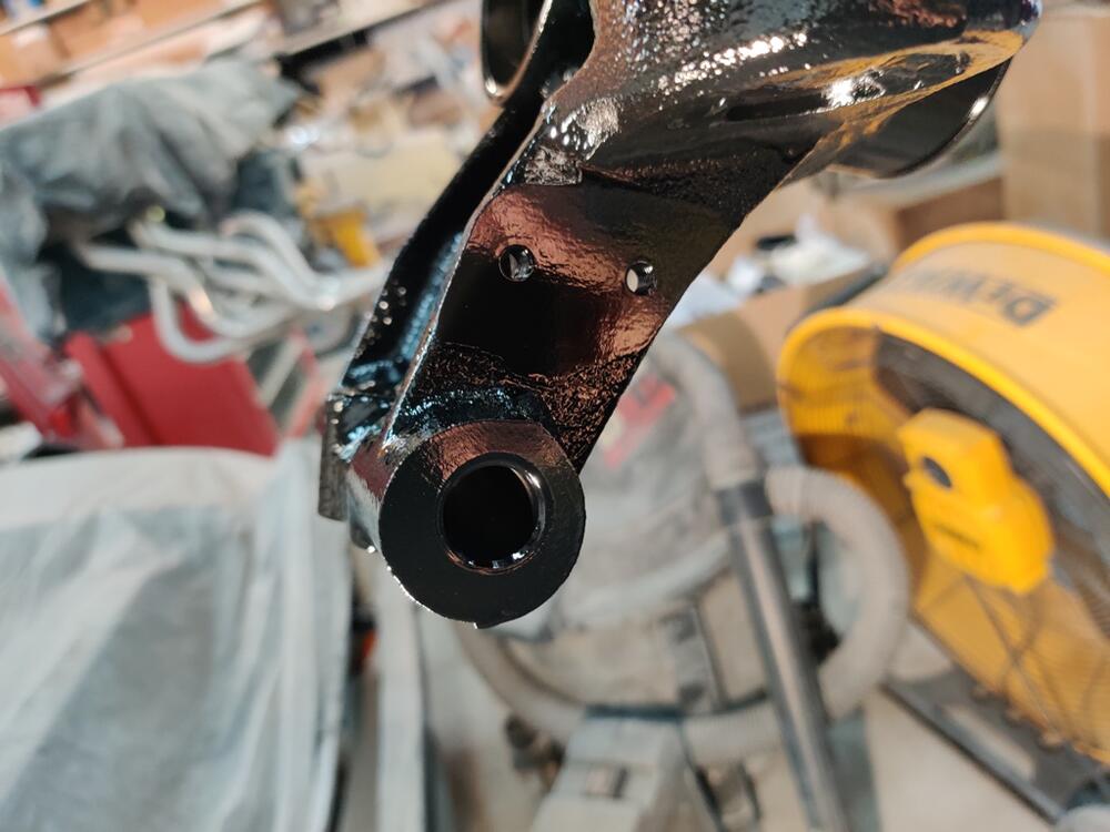
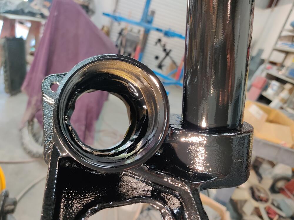
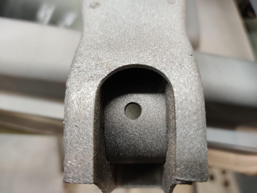
As I was glass bead blasting the axles from the car I am restoring, I noticed something I have never seen before, an arrow on the casting of the factory (I think) u-joint: I note in the direction it is pointing, it seems to me that the area of the casting between the journals is flatter than the other, similar areas. Is the arrow indicating that a grease fitting should be installed on that "corner"? Also, can you drill and install grease fittings on installed u-joints?

-
What was the cost? How do they charge for their service?
-
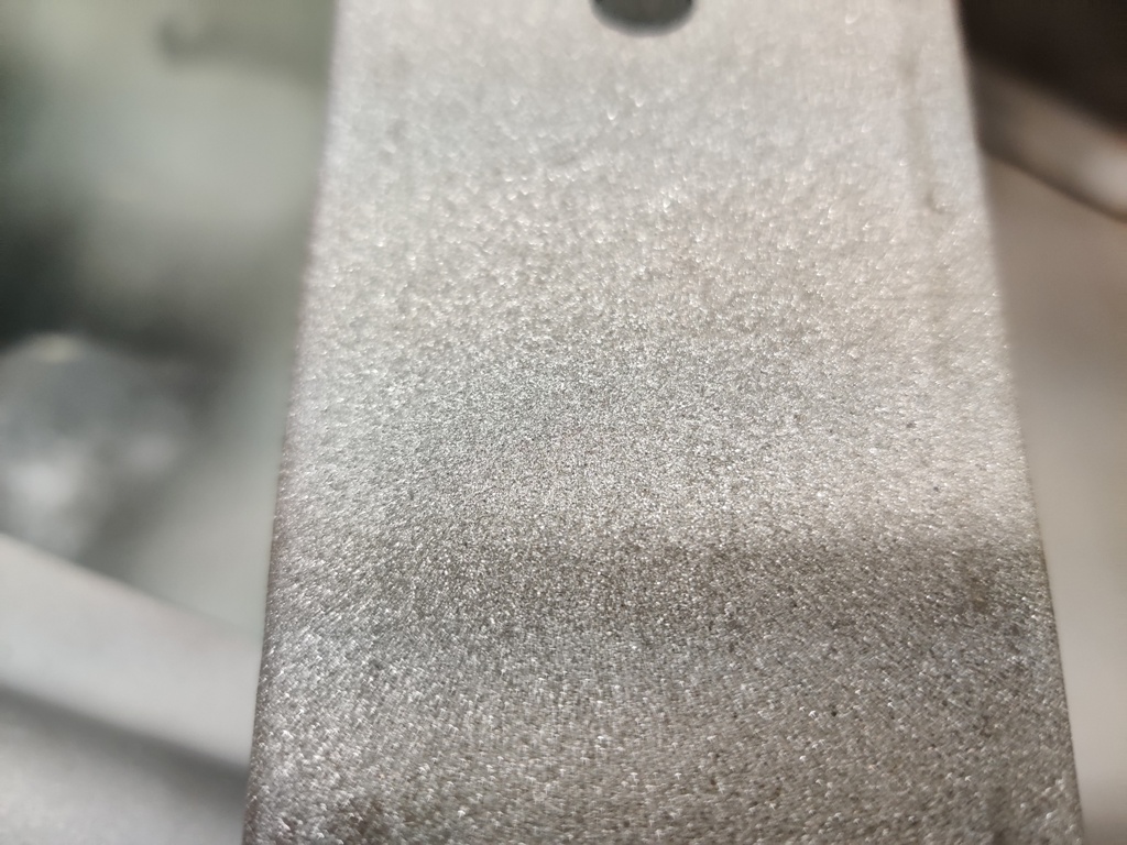
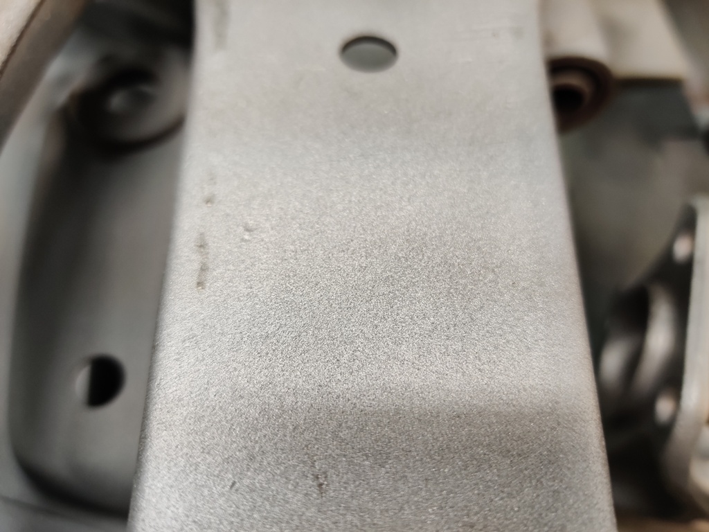
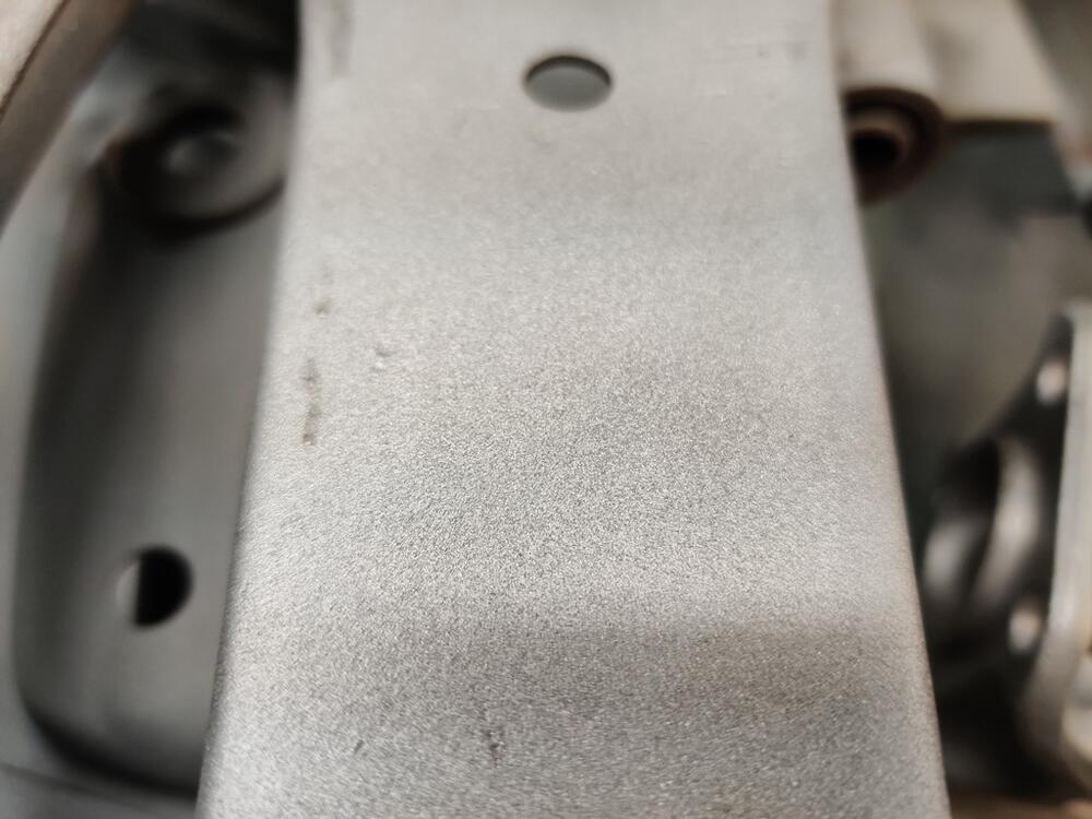
I set up for blasting parts on Saturday. It was sunny and cool, great weather for blasting. When I was using play sand, my blue tarp caught like 90% of it. Switching over and using Black Diamond (coal slag product) for the first time, I noticed two things. It is much more aggressive than play sand - Haha! And, it travels a greater distance, so my tarp wasn't catching it all. As I said previously, the plan was to blast and prime and paint all the parts from that long list at once. Right... good one. The best laid plans... I made good progress though, running through and refilling the pressure blaster 5 times over the span of about 5 hours. So, now I have switched to doing blasting on weekend days as weather permits, and priming and painting in the evenings. The black diamond leaves quite a texture on the parts: Stripping of paint and surface rust is quicker, but I didn't want to leave the texture this rough. So, I am taking each piece and running it through my glass bead cabinet to smooth out the roughness: Driveshaft u-joints appear to be original and feel like they are in great condition: So, instead of all at once, I have a few phases of "production" - some parts still to strip, some stripped bare, some epoxy primed and waiting for minor filling of scrapes and nicks, and some painted black: We'll see what the weather and this weekend allows.


-
Thanks for the info Charles. The parts I sprayed just a week or so ago all turned out with a bit more gloss than I anticipated given the 10% of flattening agent I added. Seems likely that what you indicated was in play. I got lucky with these parts in this case. I think the level of gloss is just a touch less than without the flattening agent. And, I think that matches the original parts well. The steering shaft and driveshaft, sprayed more than a year ago, are definitely duller, and the mustache bar is duller still. I think I will go with 10% again, let the solution sit for 10 minutes, and attempt to spray everything as I did last time. I weighed the individual parts of the paint solution (paint, hardener, reducer, and flattening agent) using a digital scale. So I should be able to reproduce my last effort (duly noting your info about not spraying too heavy). If I can replicate those results from a couple of weeks ago, I will be happy. I just don't want to end up with artificially glossy parts - in my opinion, that would be the result without any flattening agent. Also, the next time I spray paint on these parts, it will include all of the rest of them. So, I won't be doing several batches. The only reason I did this batch separately is that I had already blasted and primed them ages ago. For the rest, all the blasting, priming, and painting is ahead of me.
-
I bench tested the rebuilt starter tonight, and unfortunately, it didn't go as planned. The motor started spinning at a nice speed but then slowed. I thought, "that is odd... and not right". So I tested it again - brief amounts of juice and it would repeat the same behavior. So, about on the fourth test, I kept current applied for a bit longer, and I saw a bit of grease or oil bubble up off of the back bushing. I stopped immediately. I wiped the drop of oil that formed off with my finger and detected that the backend of the armature and the bushing were quite hot. Yeah... So, I took the starter back apart and long story short, made another round of using the 320 grit lapping paste on the front and rear bushings. When I reassembled, I checked that the pinion gear rotated nicely by hand. Then I torqued the fasteners, checked pinion gear rotation by hand one last time, and bench checked again. This time the motor spun very nicely and didn't slow down at all. I checked for heat at the front and the back and only detected a small amount of warmth, not hot at all. Would have been a problem had I mounted it on the car without checking!
-
Both of my Z's had the bolts oriented with nuts on the lower side (12/70 and 6/71 production dates)
-
Thank you for the tip!