inline6
 Subscriber
-
Joined
-
Last visited
Everything posted by inline6
-
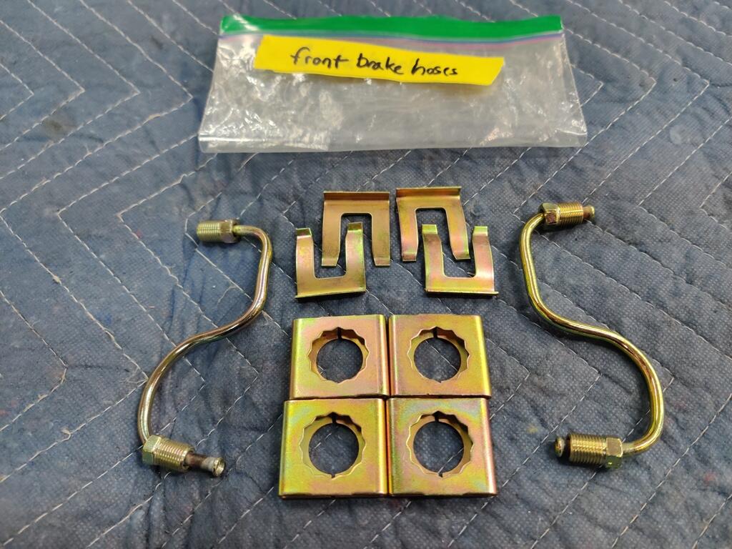
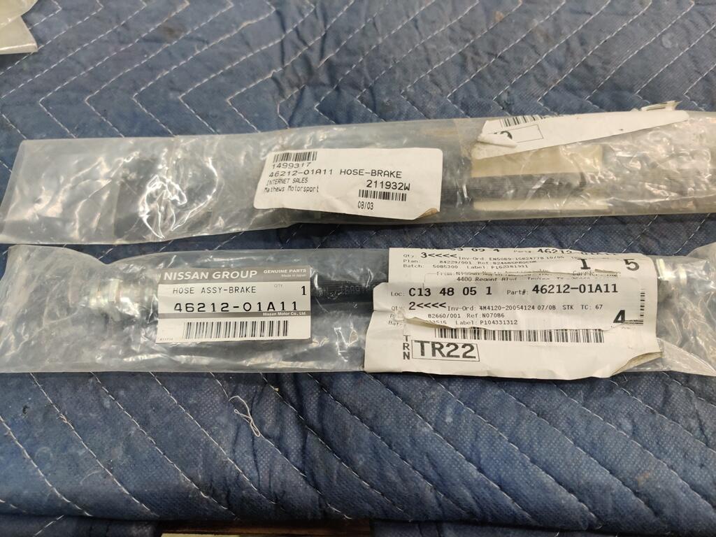
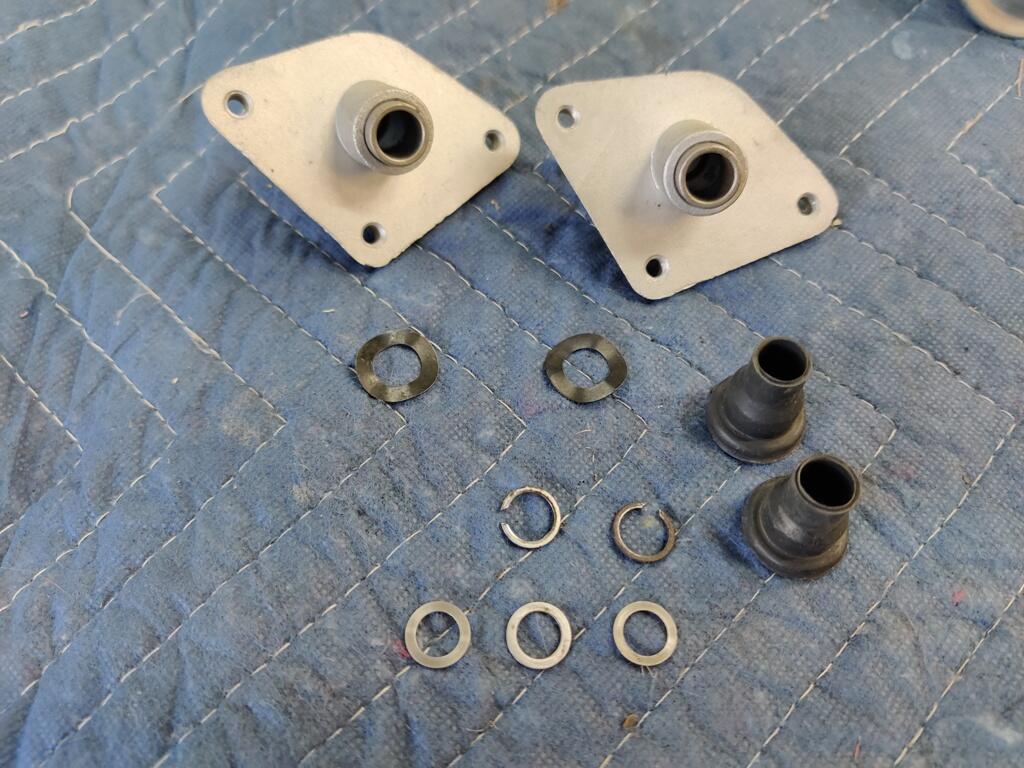
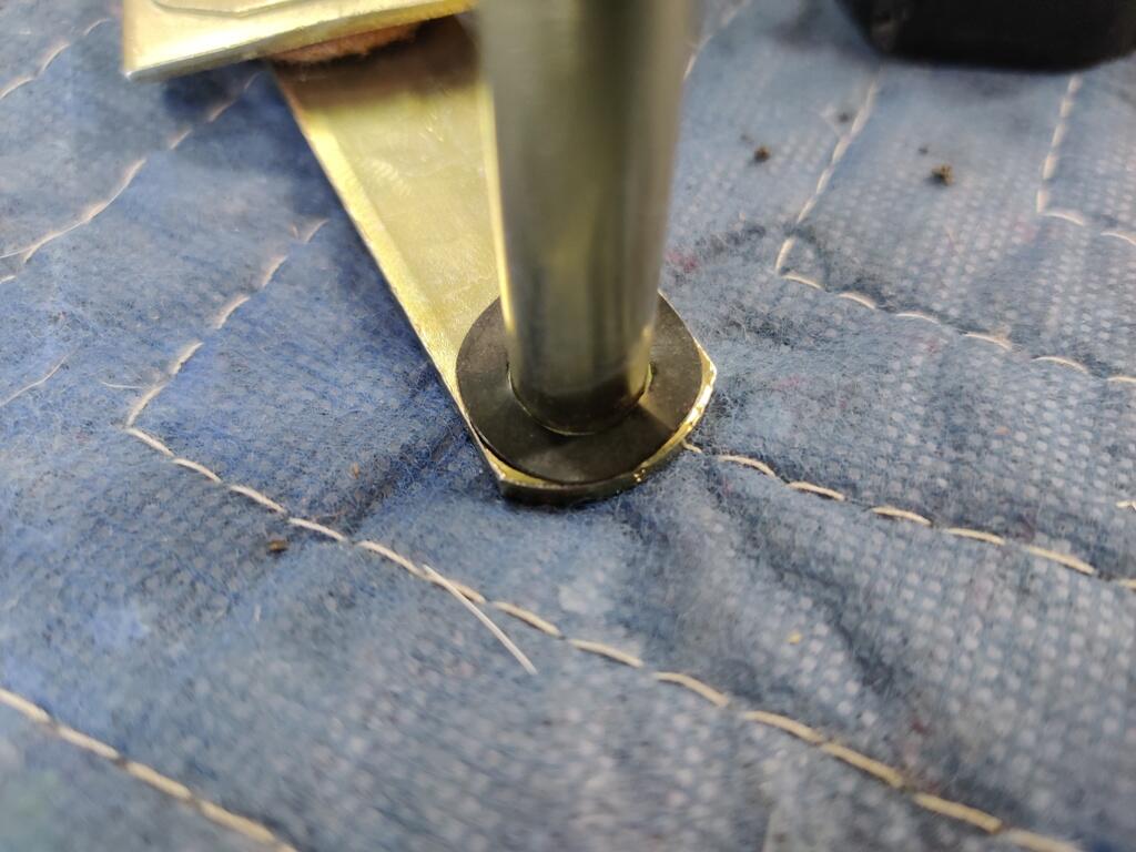
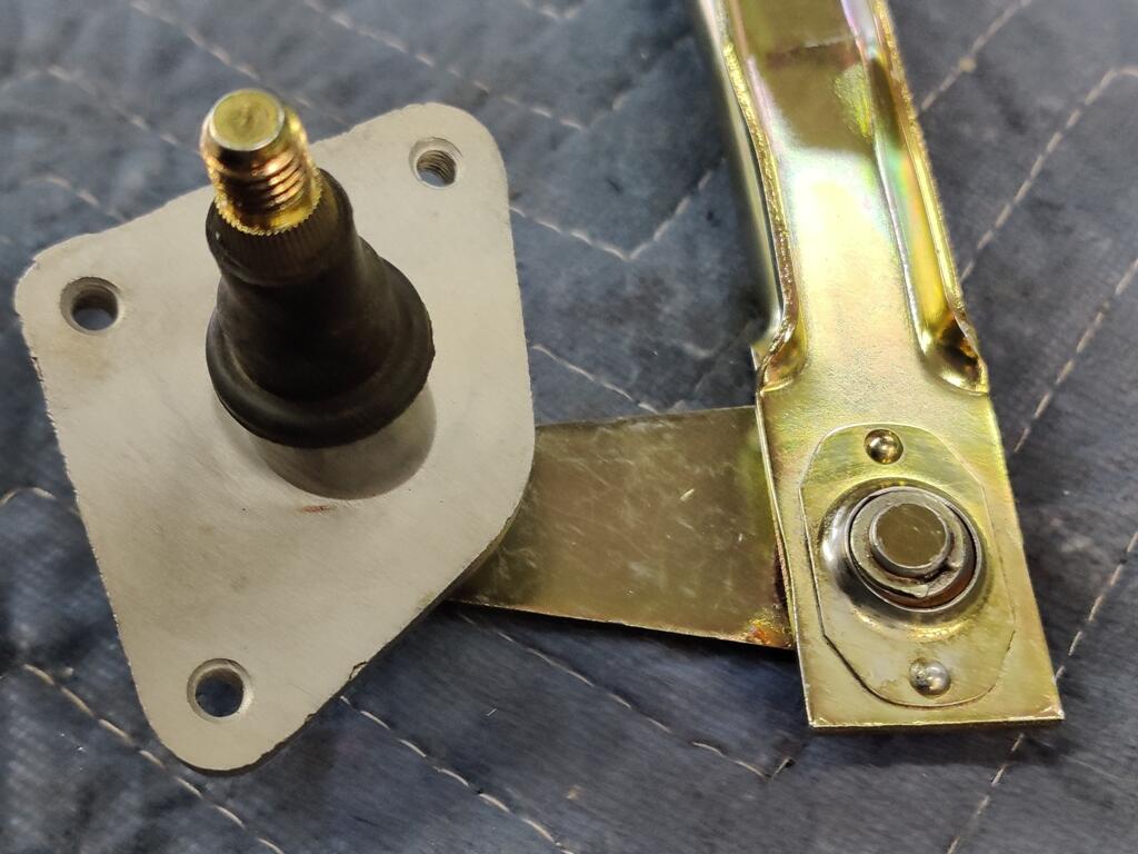
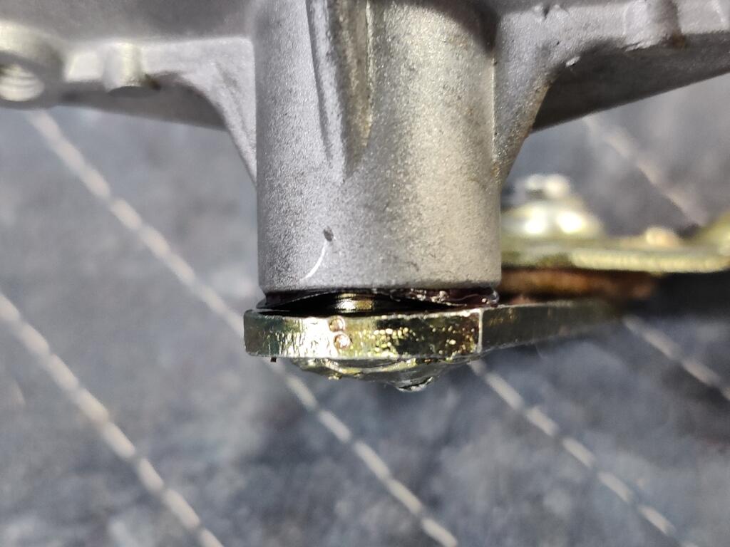
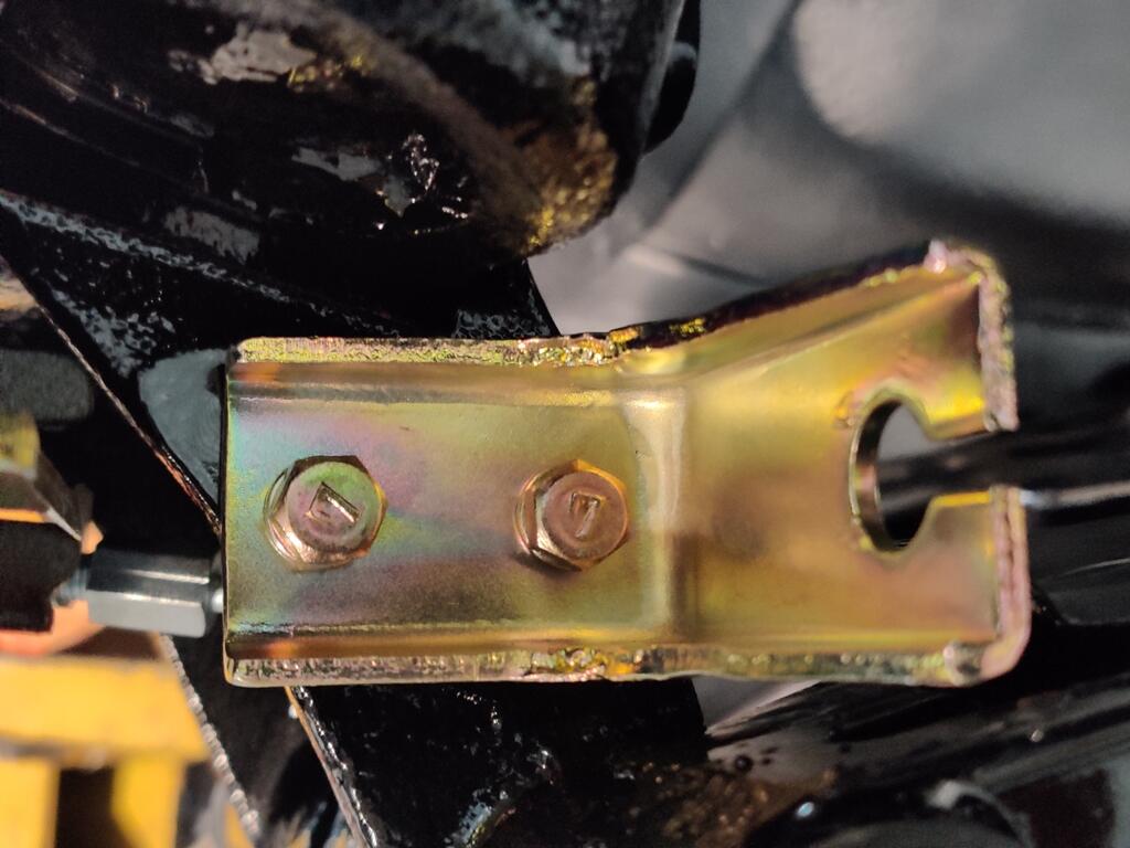
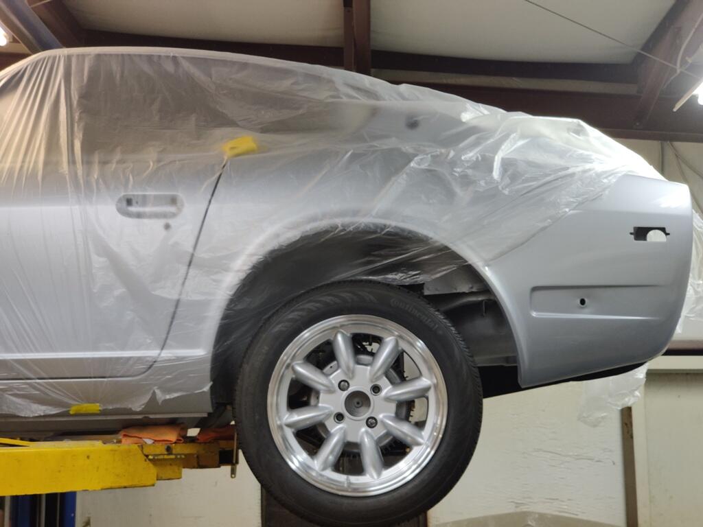
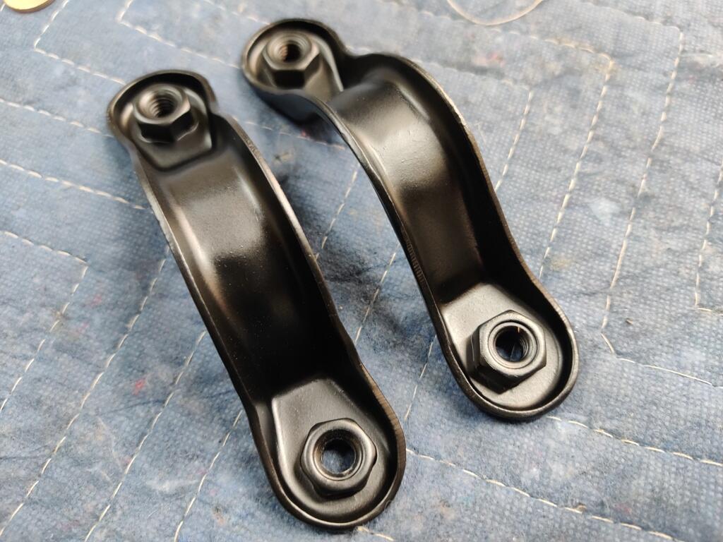
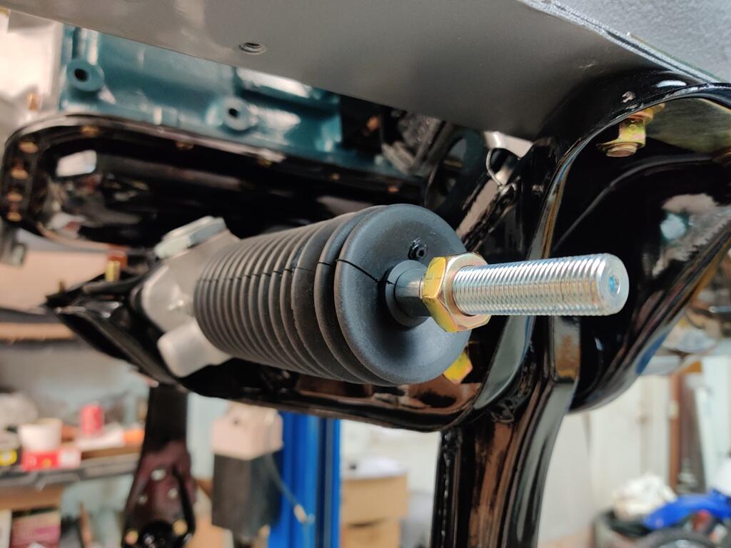
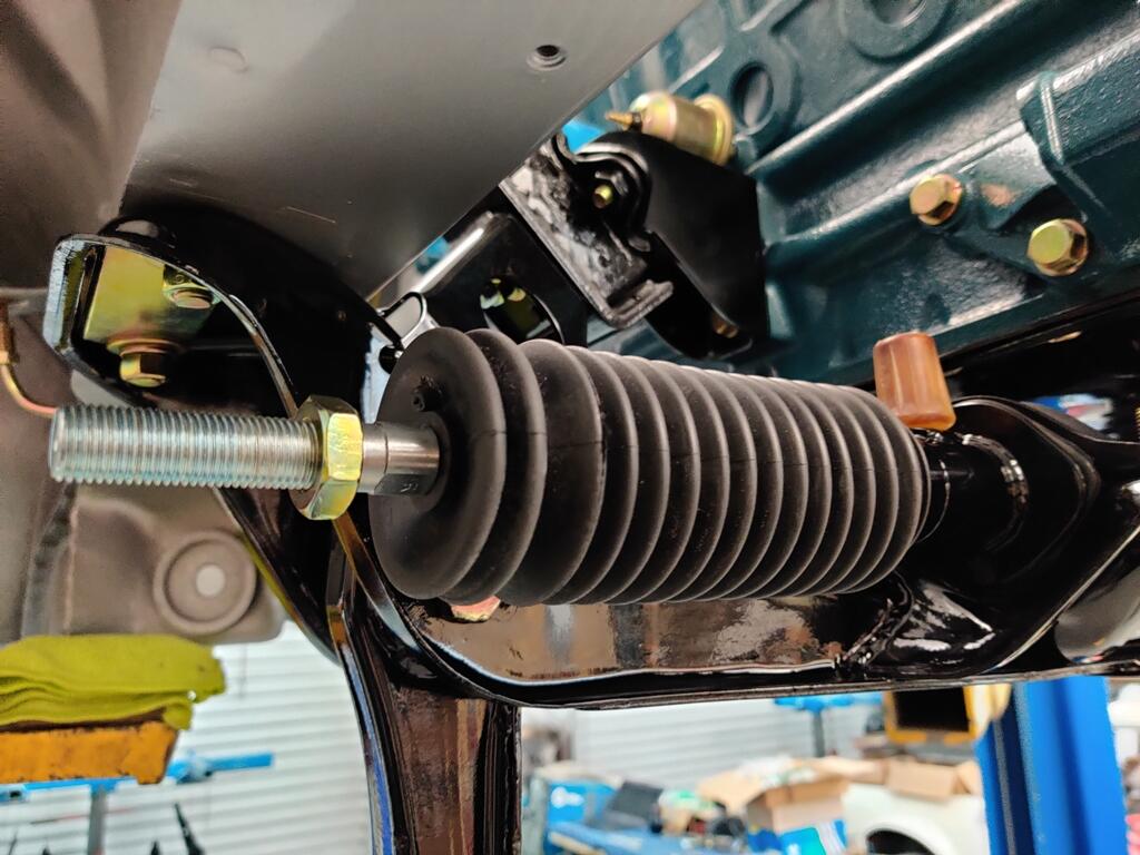
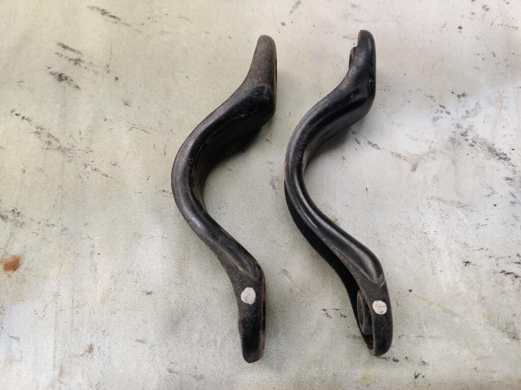
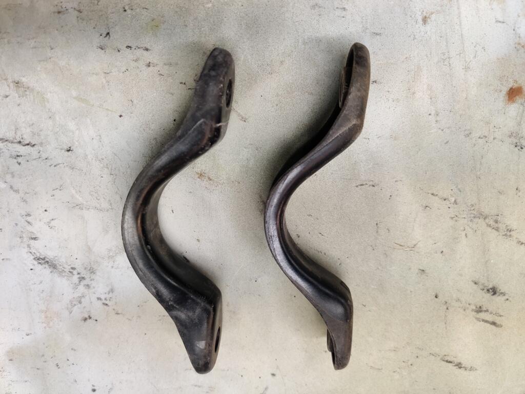
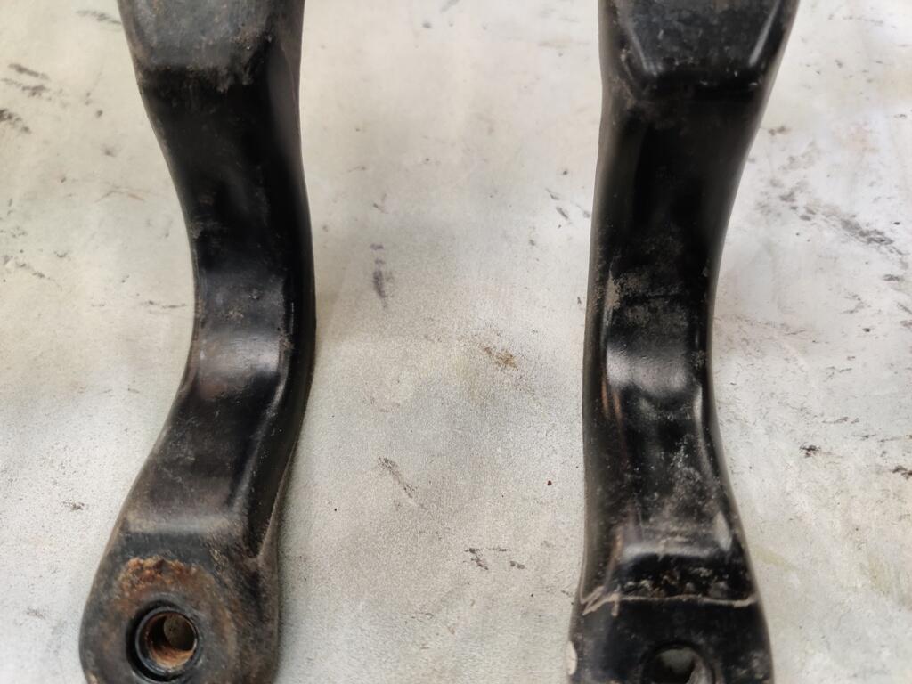
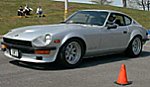
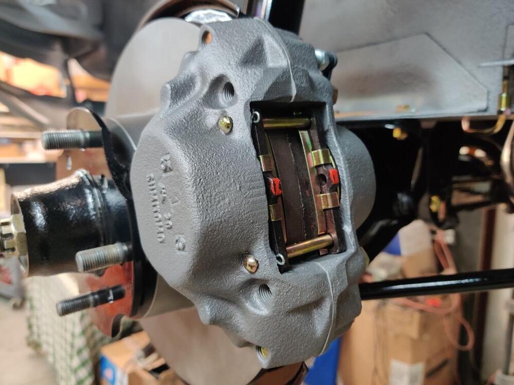
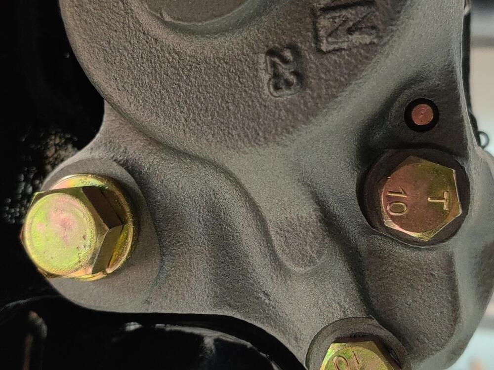
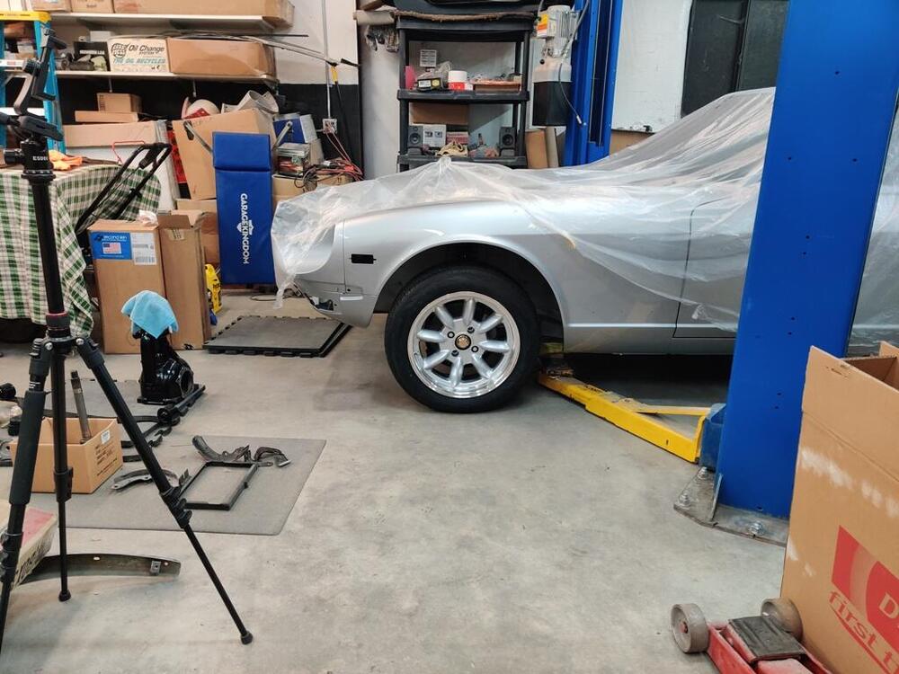
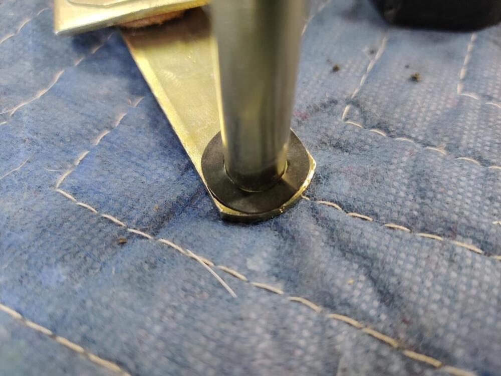
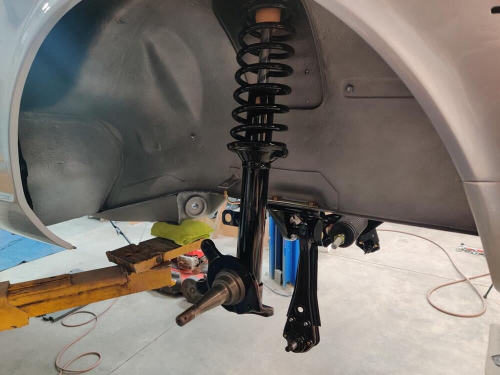
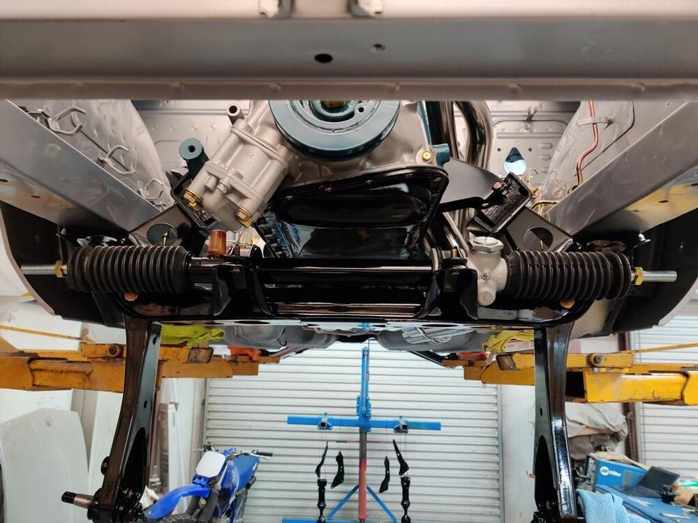
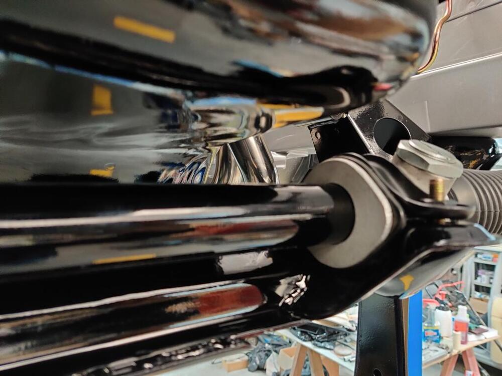
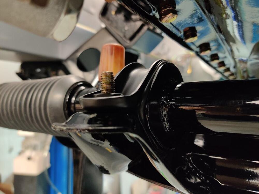
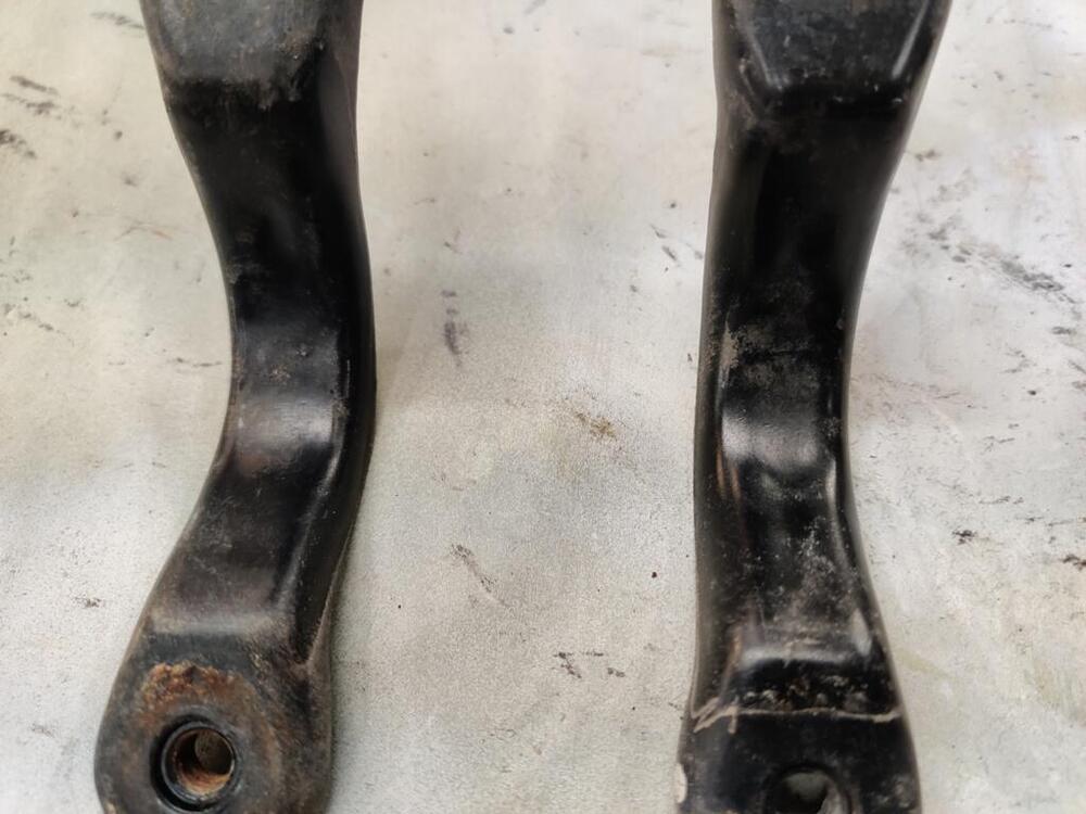
 With the left front strut on the car finally, I was able to move forward with getting the front suspension assembled. I also put the outer tie rods on, and the front brake calipers, little "s" hard lines and brake hoses. I also removed the steering rack clamps and took a couple of pictures of them, trying to capture the differences from front and rear that I saw. I hadn't torqued the brake caliper "bridge" bolts (the ones with T 10 on them), so I did that (~39 ft-lbs.) before installing the calipers. The "s" hard lines required a lot of fiddling. Literally every hard line I sent to get plated got "jacked up" - I don't know why. For the steering rack "clamps", I didn't see a difference in the "arch" portion. Instead, I noted that the angle of the "feet" is different. In these first two pictures, you can see that one "foot" sits flat, whereas the other, does not. I also think I see that one "foot" is slightly longer than the other - in the third pic here, the "foot" on the right has a bit more length from the hole to where it starts sloping upwards. I found it difficult to install them incorrectly. The back bolt won't thread easily into the bracket if you have it reversed (front to back). I found the best fit by placing the longer "foot" it in the back location. After completing these things, I was able to set the car down on all four wheels for the first time in 5 years! Even with the Suspension Techniques springs, the car looks like it's four wheel drive. Bummer. Part of the issue is there is still a fair amount of weight that is not yet on the car. It has none of the interior, none of the glass, none of the door hardware, no hood, no bumpers, etc. I hope that additional weight will make a big difference. However, I think the tires I bought are part of the issue. They are 195/55-16, which have a 24.4 inch diameter, whereas the stock tire diameter was 25.3 inches. So, not quite 1/2 of an inch of tire is "missing" from the wheel well. I'll see how it looks when it is fully assembled and has been driven for a few hundred miles. If it still looks awkward, I will swap the tires out for something a bit bigger. Starting to come together though!
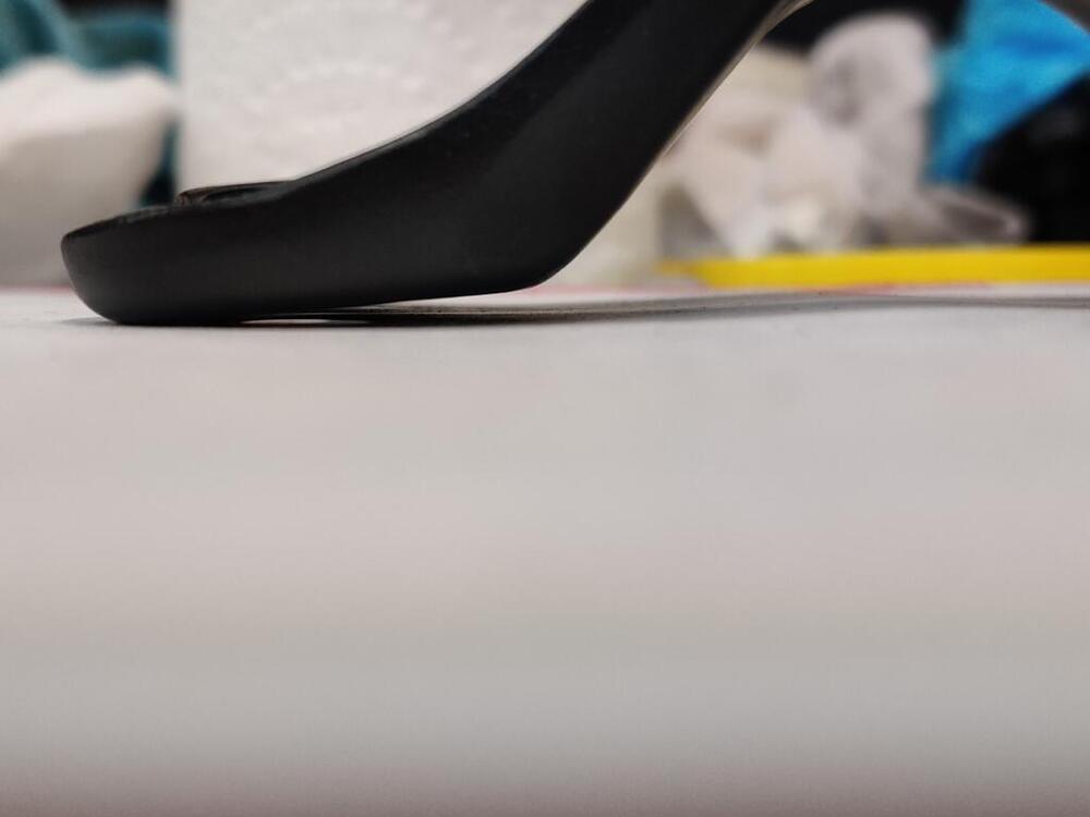


-
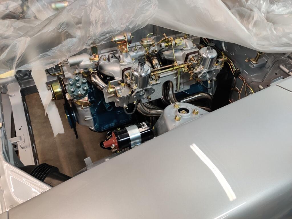
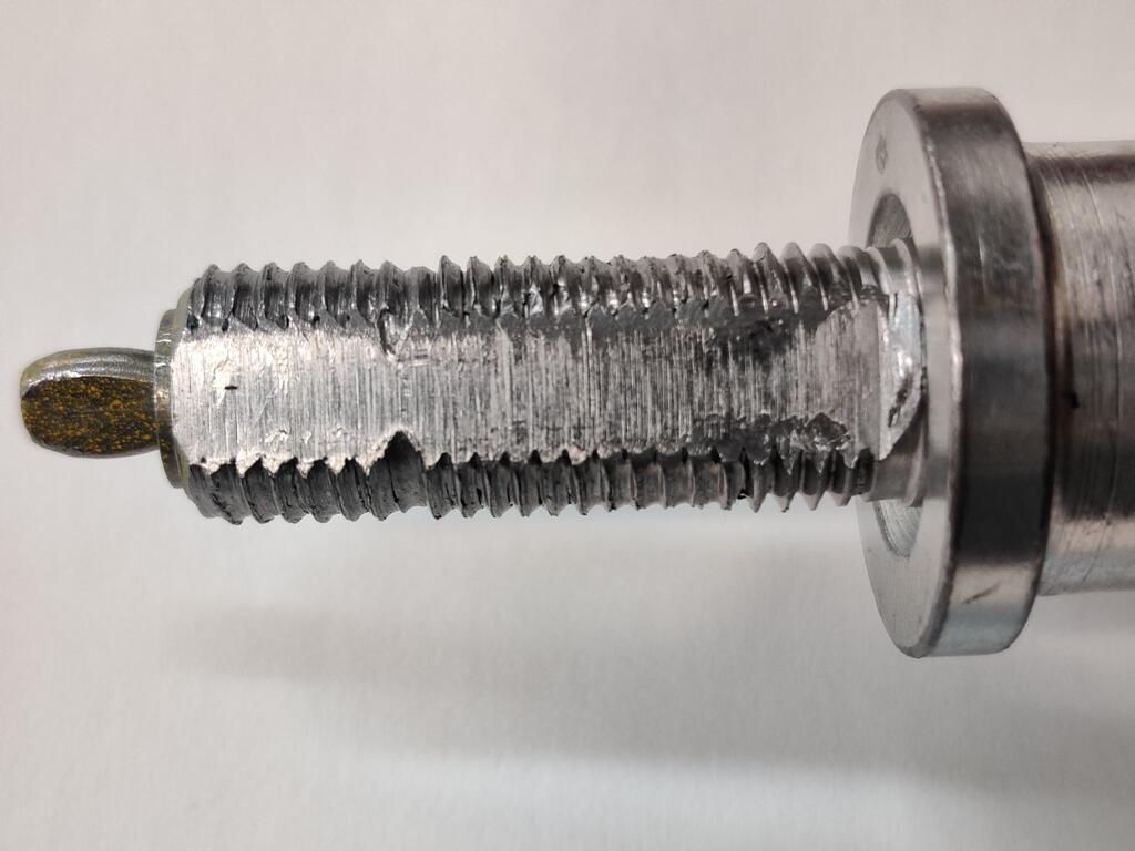
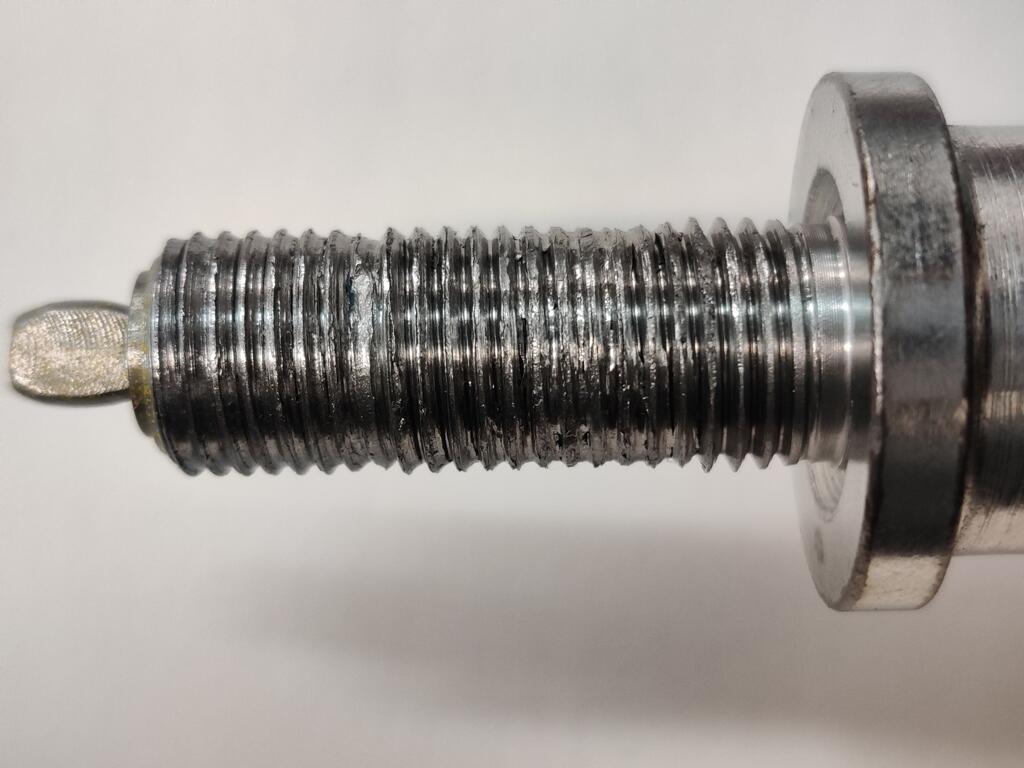
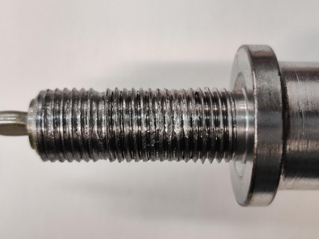
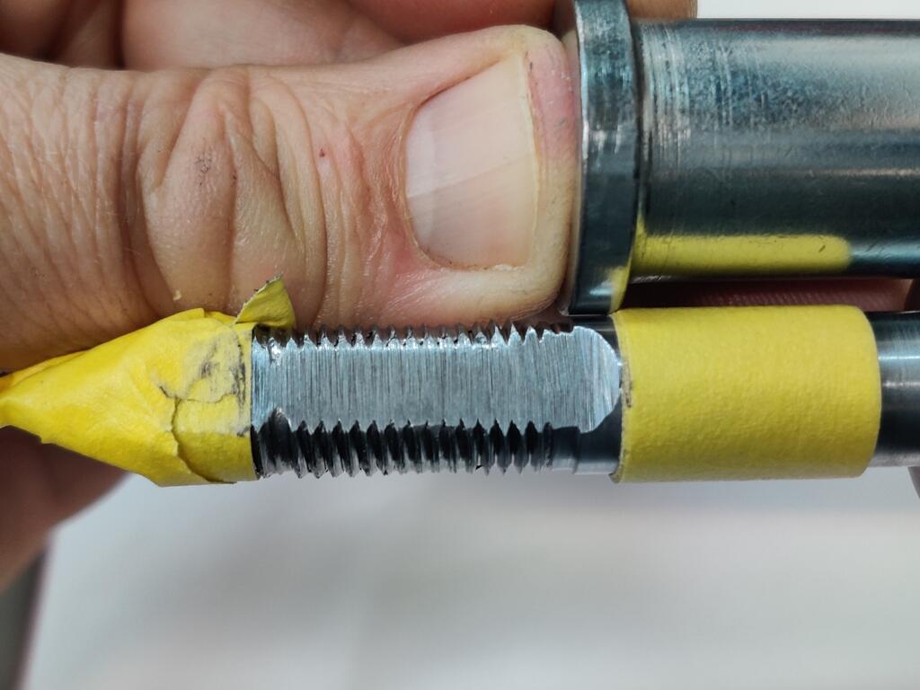
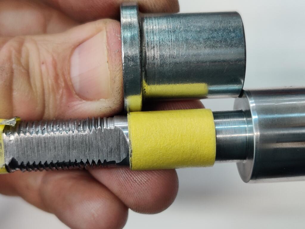
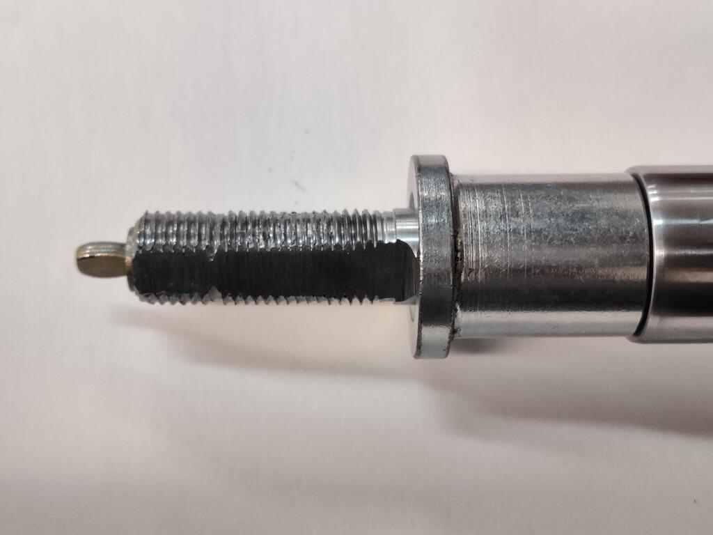
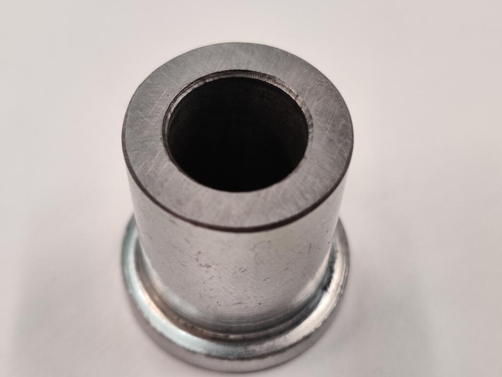
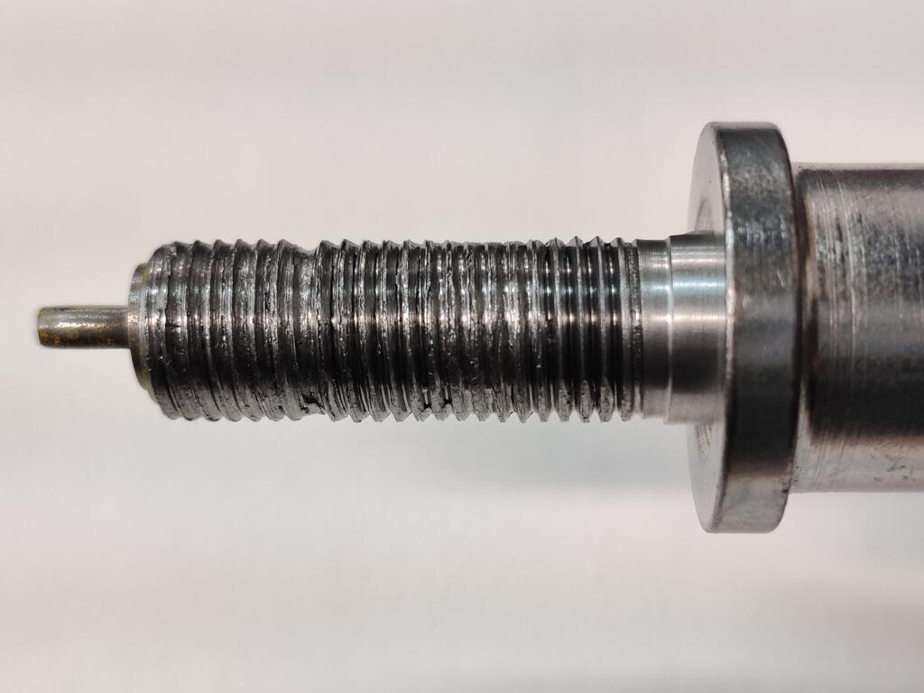
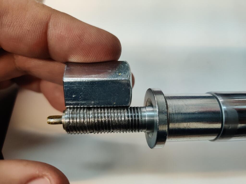
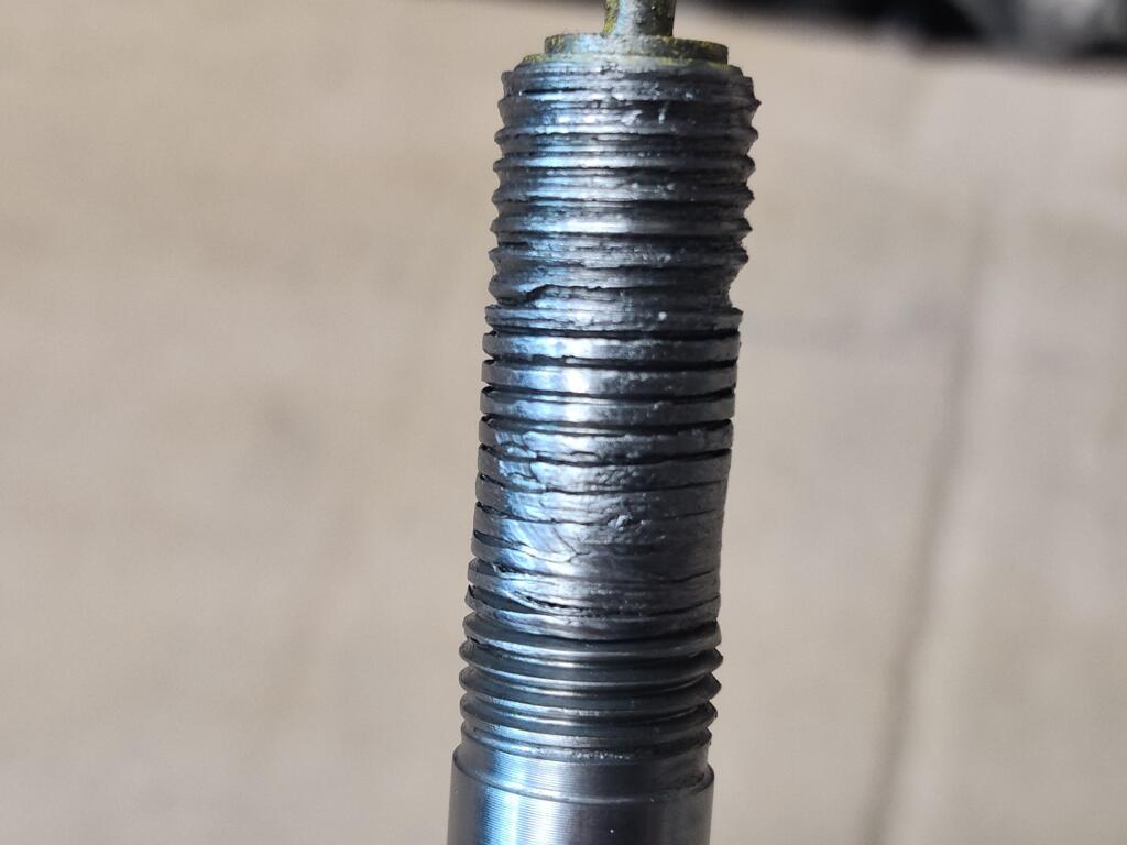
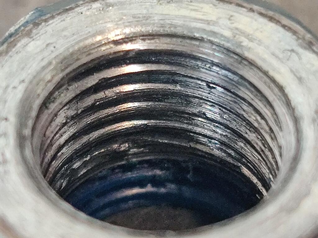
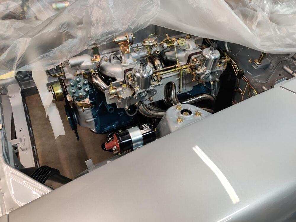
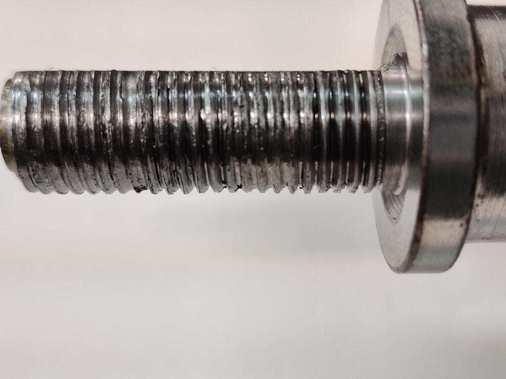
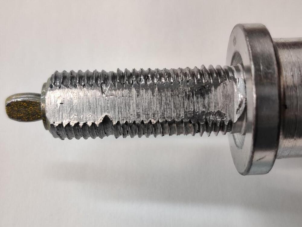
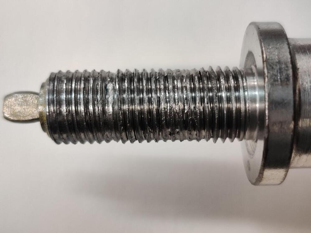
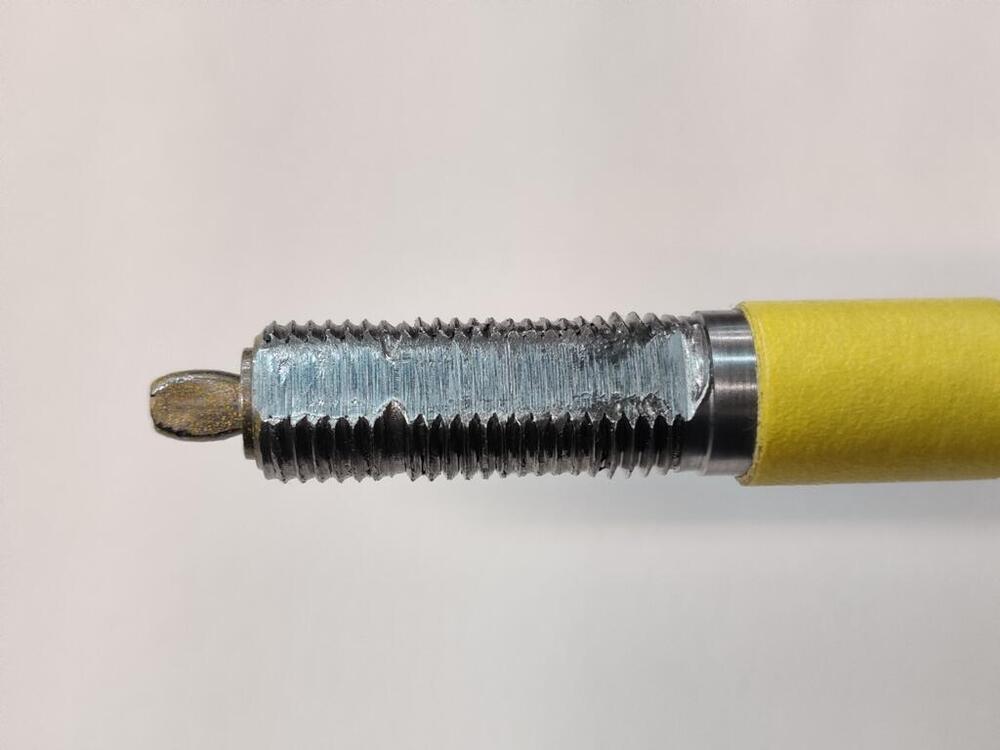
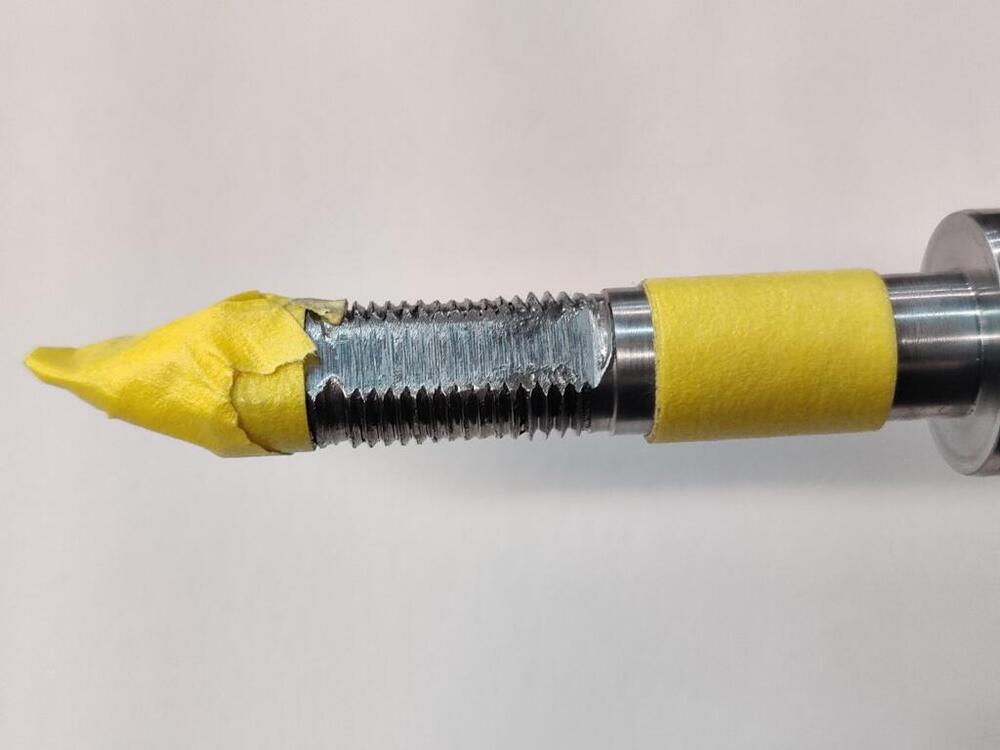
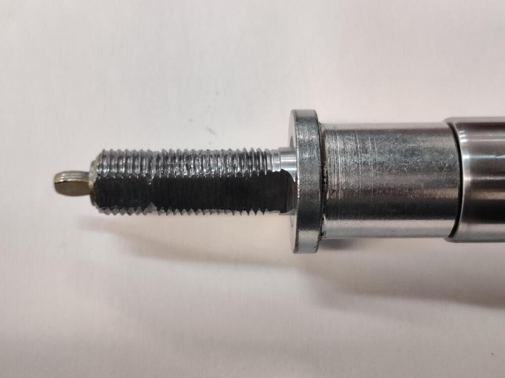
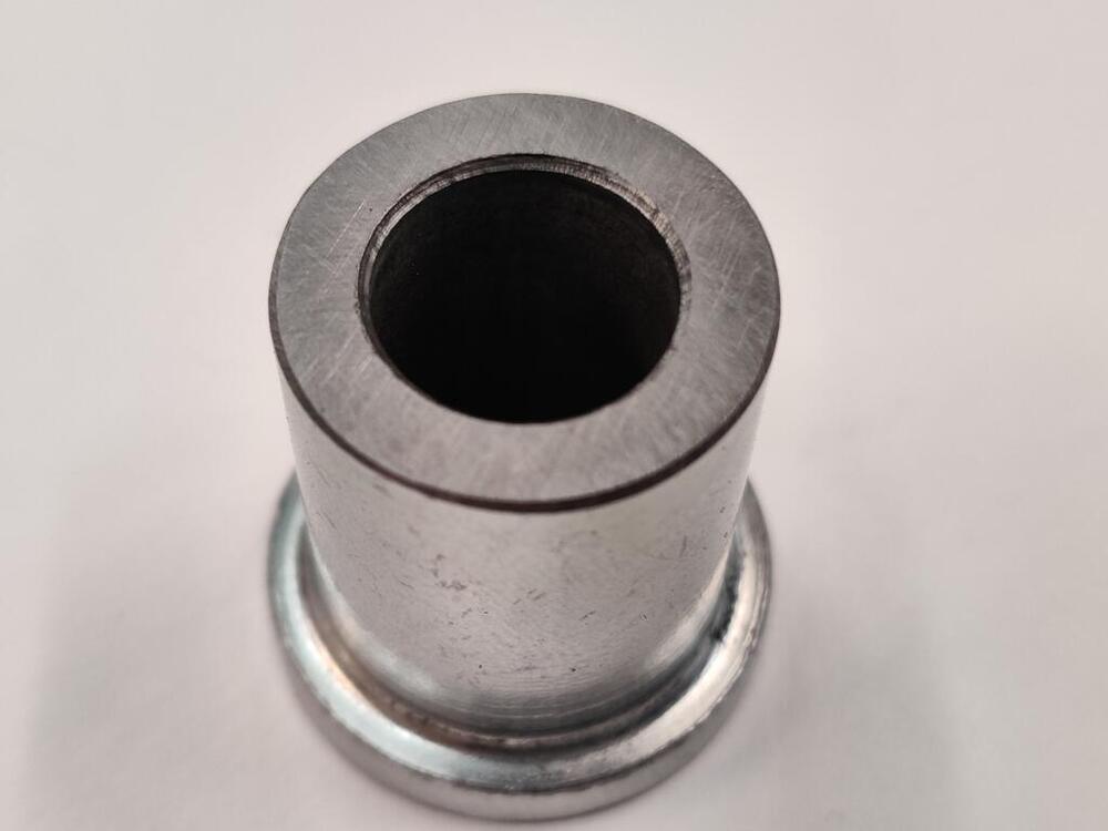
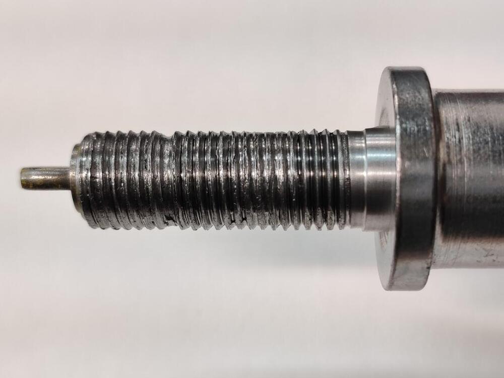
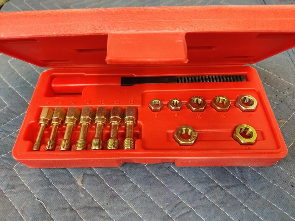
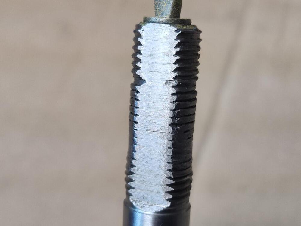
Yeah, it is not obvious which is the right torque value. I decided to try to save the strut insert and spent a couple of hours giving careful attention to the threads. I used this tool which is for repairing threads: Using a lot of patience, I kept at it until the new coupler nut would thread on without difficulty. Here's how it looked after all that effort - these pictures capture how it looks all the way around the circumference. While not "great", the threads look better than before. Also, note that the 4 to 5 threads just above the spacer (a bit more than a 1/4") were not mangled because the thickness of the isolator stacked on the spacer protected them. As I examined the situation, I determined that I could "alter" things a little bit, so I could utilize those threads. Basically, by shortening the spacer, the isolator can slide down further on the shaft and expose those threads to the fastener. I started by putting tape on the shaft to mark the area that I needed to grind to fit the "D" in the upper strut mount isolator. And, I taped off the adjustment mechanism to keep metal dust from getting into it. After using a belt sander to grind the "flat" in the shaft a little lower, I had to remove the same length of material from the bottom of the spacer. I don't have a lathe, so I had to be very careful with grinding. After removing some length, I very, very carefully used the side (which I have never used) of my 8" bench grinder wheel and kept measuring with vernier calipers until the cut side was square with the non-cut side. Then, I chamfered edges (middle pic). The shortened spacer length matches the shaft again (third pic here): Final pics, with the third pic here showing the coupler nut after shortening it also. I could have shortened the spacer and the nut a bit more to pick up another couple of good threads. However, given that the original nut only engaged about 7 threads, and this one engages more than double that (though some are in very bad shape), I felt grabbing those last two was not necessary. Today, I assembled the strut, put it on the car, and used that same torque wrench to set the nut to 37 ft lbs without any issue whatsoever. I used a good bit of blue Locktight, which will keep the nut from backing off. I plan to check the torque on that nut repeatedly as I put the first 500 to 1000 miles on the car. If it turns when retorqueing or feels odd at all, I will swap the insert for a new one.


-
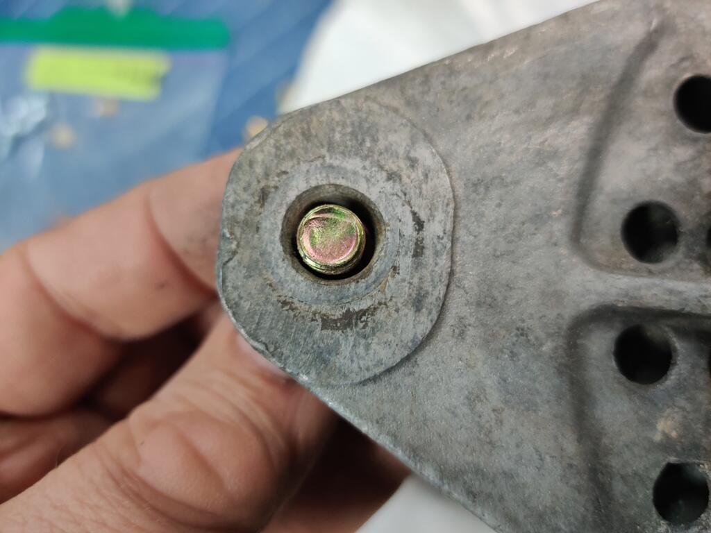
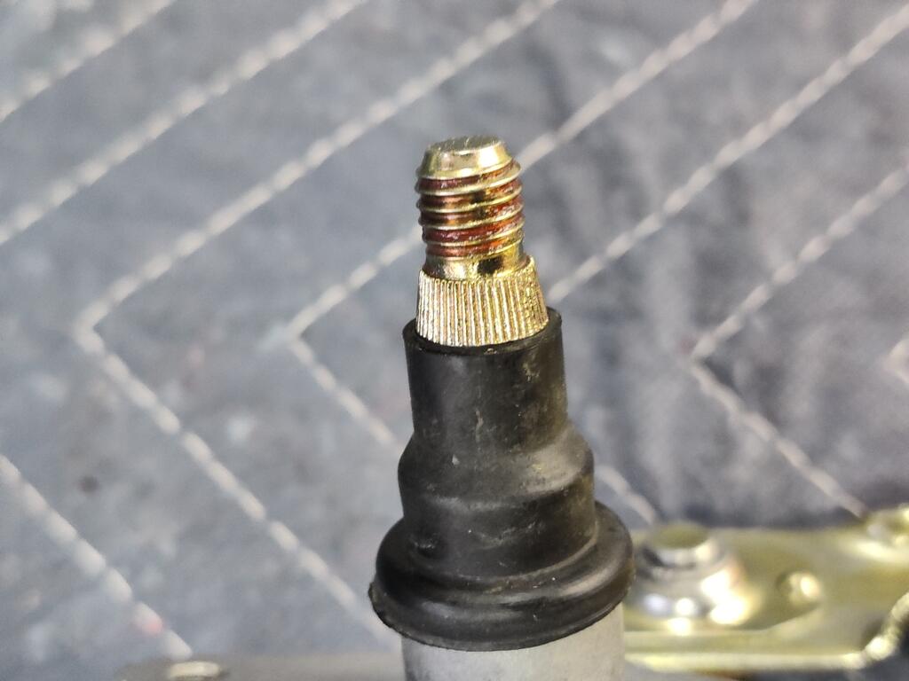
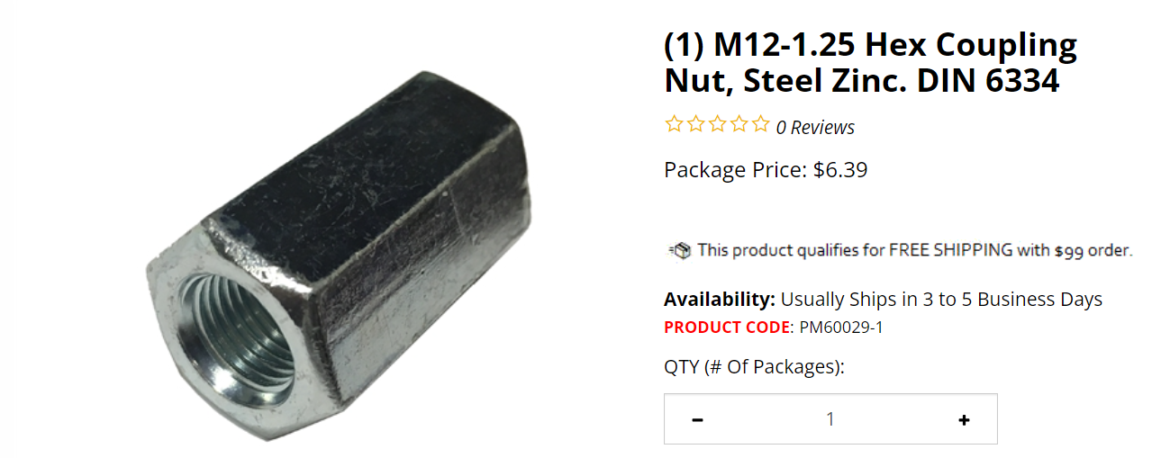
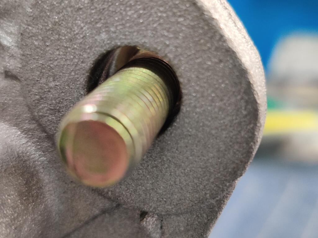
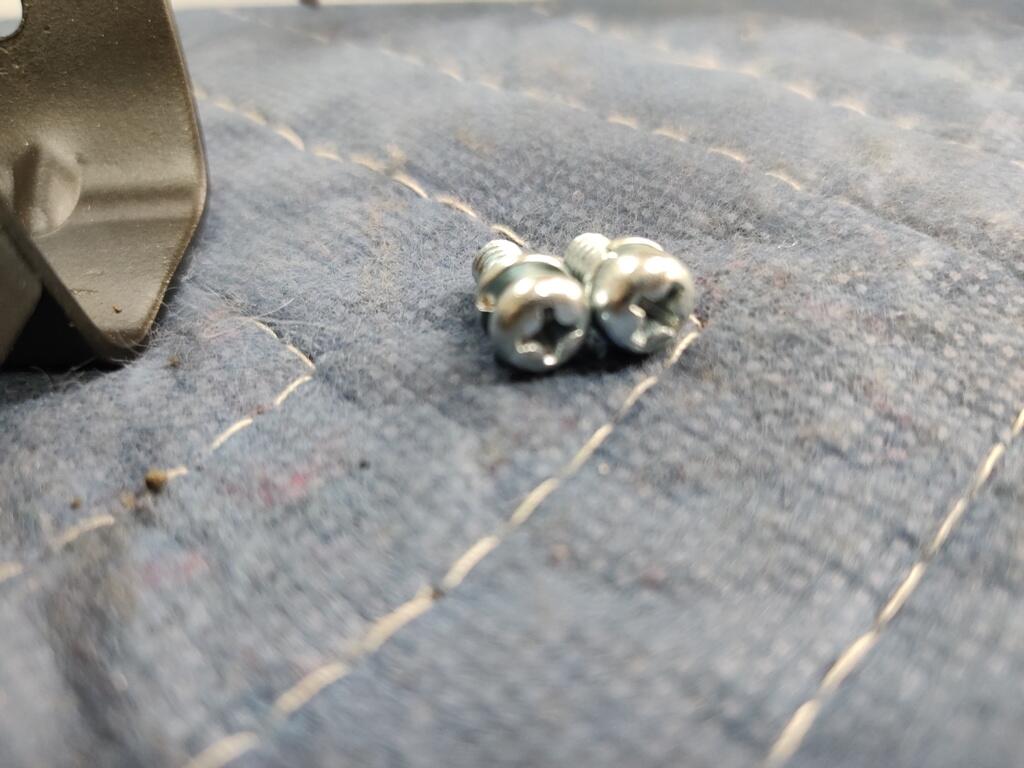
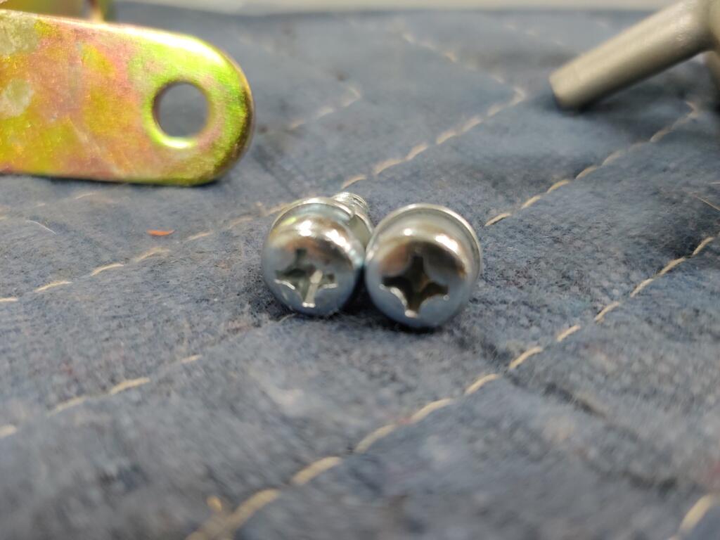
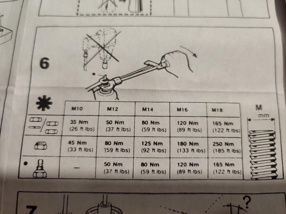
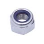
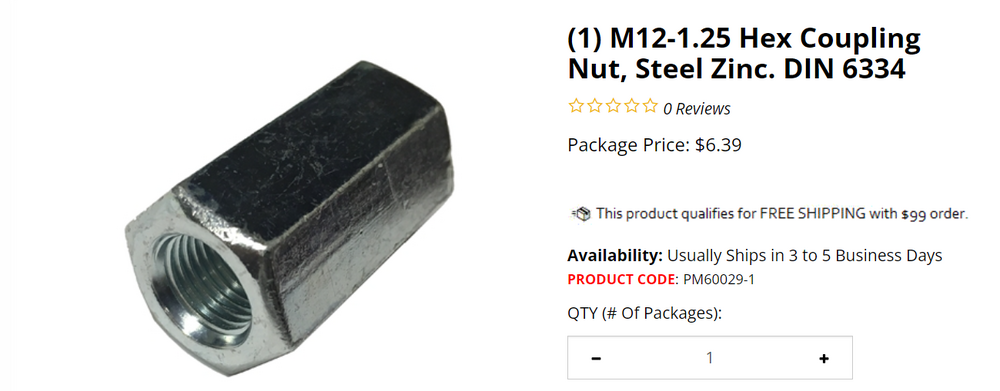
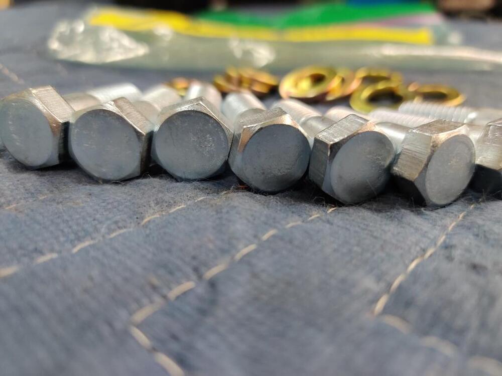
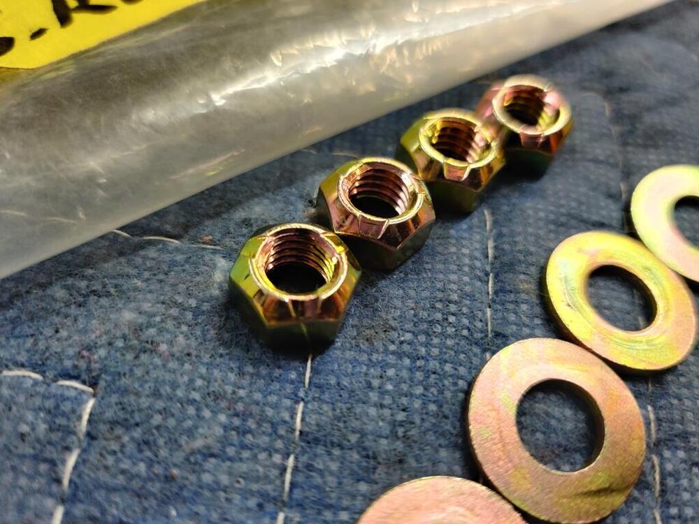
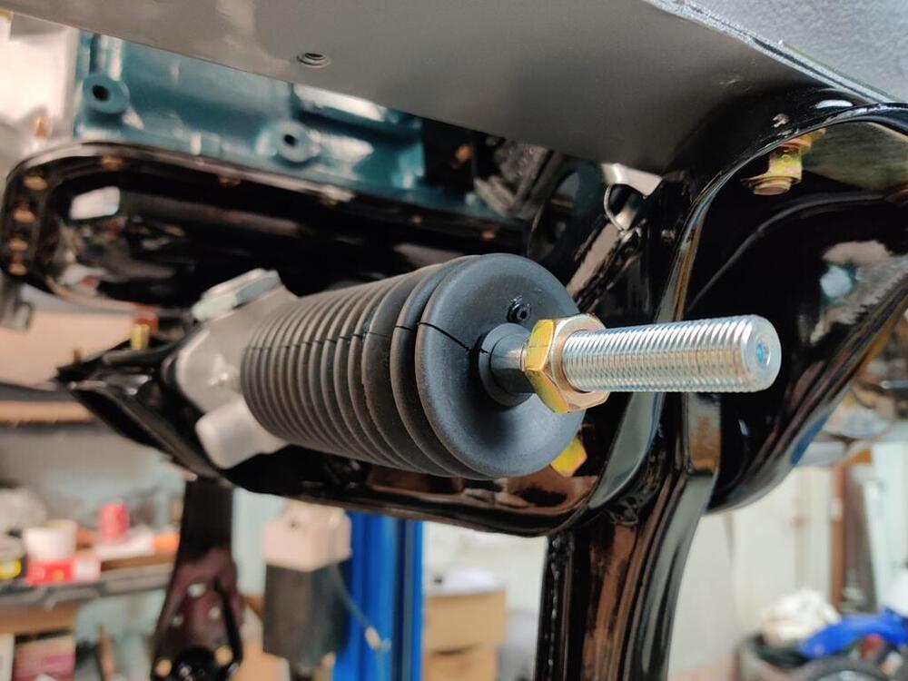
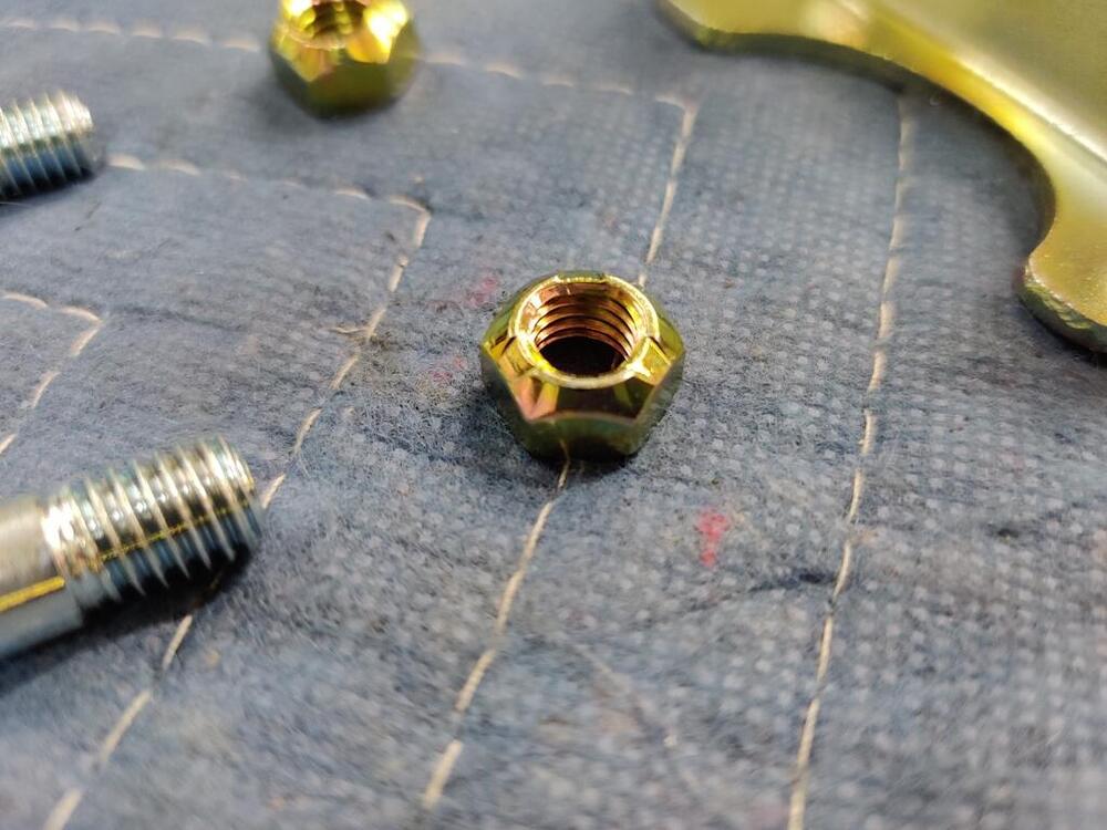
Appreciate the info and thanks for the support. I don't want to say, but it is accurate to say... that for that one nut, I know I tightened it more than the 37 ft-lbs. It just became obvious from my experience of torqueing fasteners, even though the digital torque wrench failed to indicate when I hit 37 ft-lbs. It has an "auto off" feature after about a minute of time to save battery life, so maybe it turned itself off before I used it on that nut. However, I still believe I was being exceedingly careful and believe I checked the display to confirm the correct setting just before attempting to torque that nut. As far as the directions go, I definitely did not like them. There were hardly any words... an over reliance on pictures. Saves on translation, but doesn't convey info precisely either. I already mentioned that I used coolant in the strut tubes originally because of the snowflake symbol. So, now take a look at this and tell me what you would torque the nut that is supplied with the struts to. I will give you a start with the threads being 12M X 1.25 and a picture of the supplied nut: Think everyone gets it?
-
Heard. Die was supposed to be delivered yesterday. Tracking from USPS still just shows "in transit". Lame. Trying to accept my fate. With all the money I am spending on this car, another $190 isn't the end of the world, but the dollars aren't fully my issue either. I hate the waste of an otherwise new and perfect strut insert. 😞
-
I read about the galling issue in that first link. I also read Koni's response and decided that they wouldn't have supplied nuts that were not correct for the application. FWIW, they say they are chrome plated steel and not stainless. And, I was determined to be careful to go slowly and to not over torque them to avoid problems. I blame the digital torque wrench for having an intermittent failure. But, that doesn't help me now. With about a 1/4 of the threads on the shaft machined off, one would think that a taller nut engaging more of the threads might be a good idea to help prevent damaging the threads when some amount of over torque occurs? But yeah, once the threads get wrecked, there is a bunch of metal floating around between the nut and the shaft threads. And evidently, it is certain that a stainless nut (if it is) exacerbates the problem of getting the nut off because of heat. Is the shaft stainless? If so, why would Koni supply these nuts? It is a mistake?
-
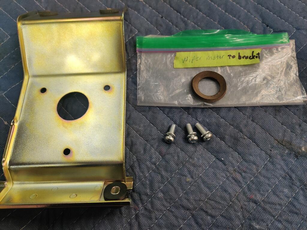
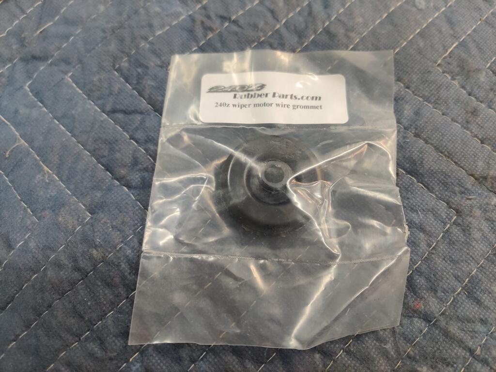
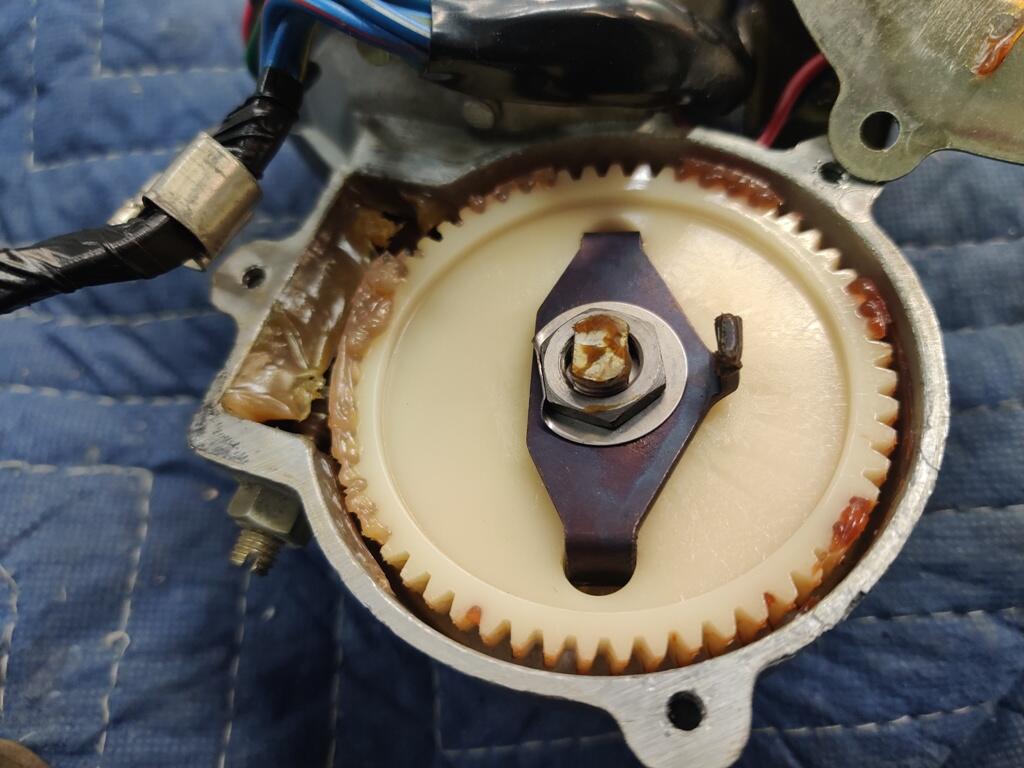
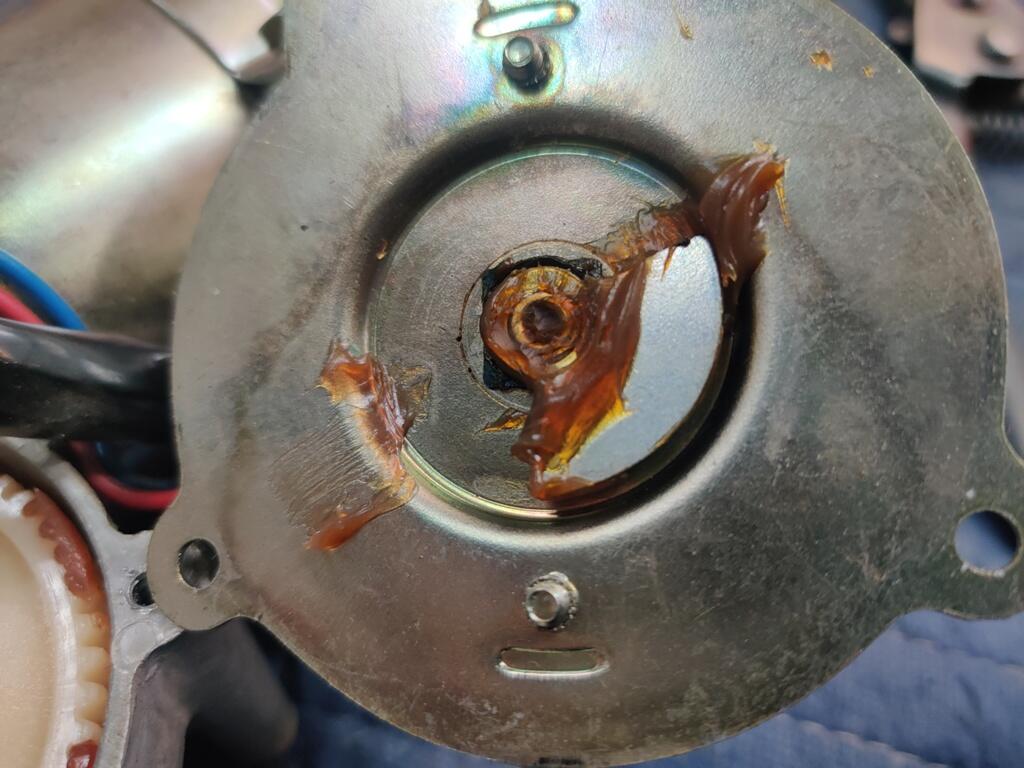
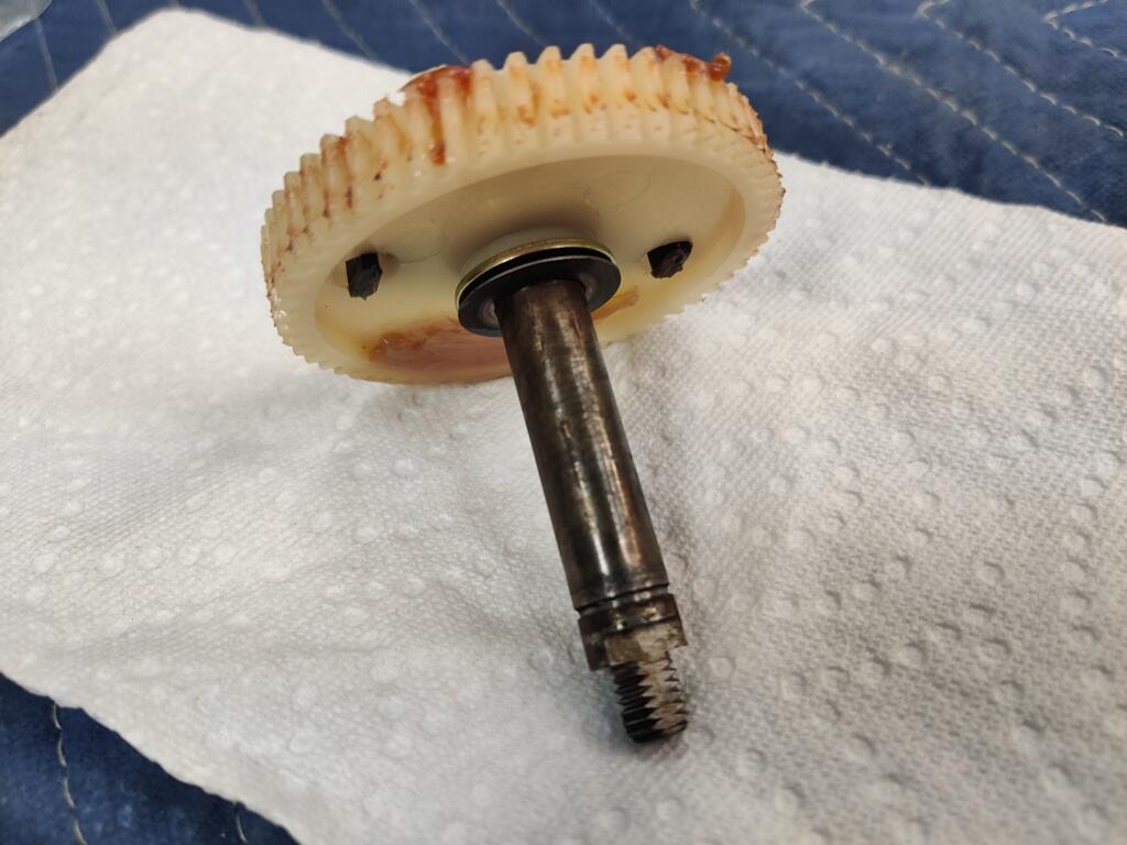
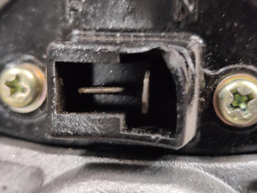
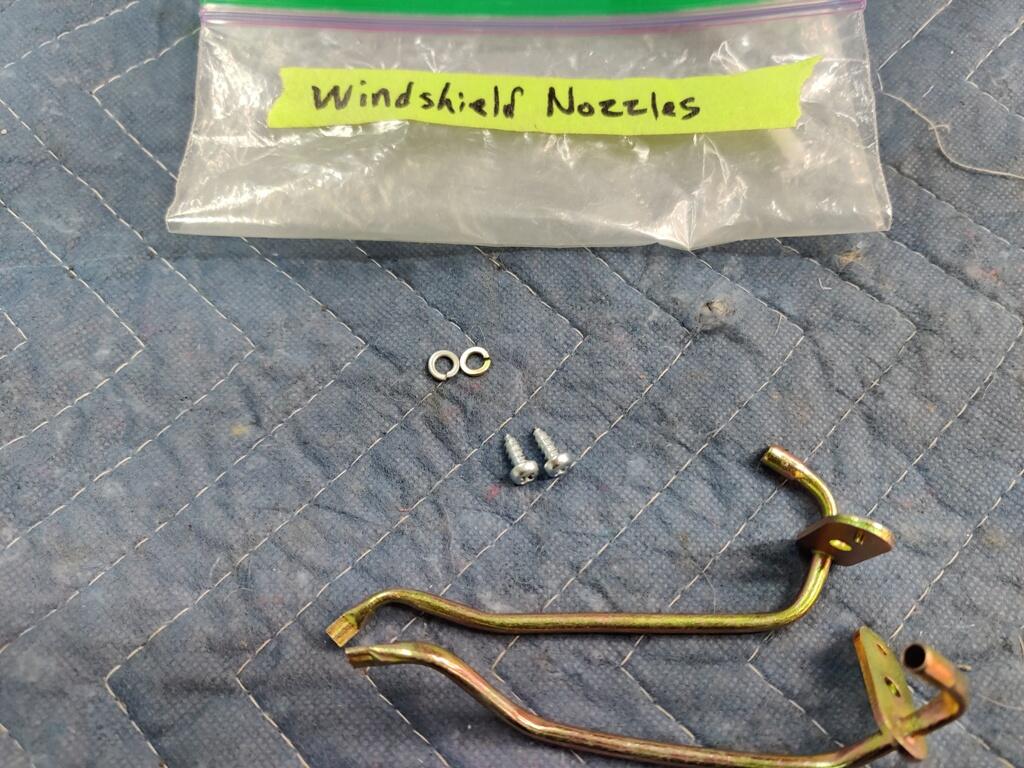
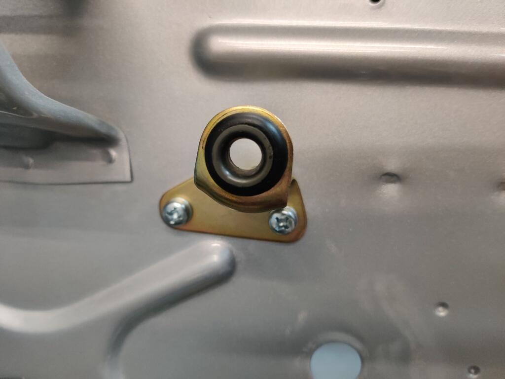
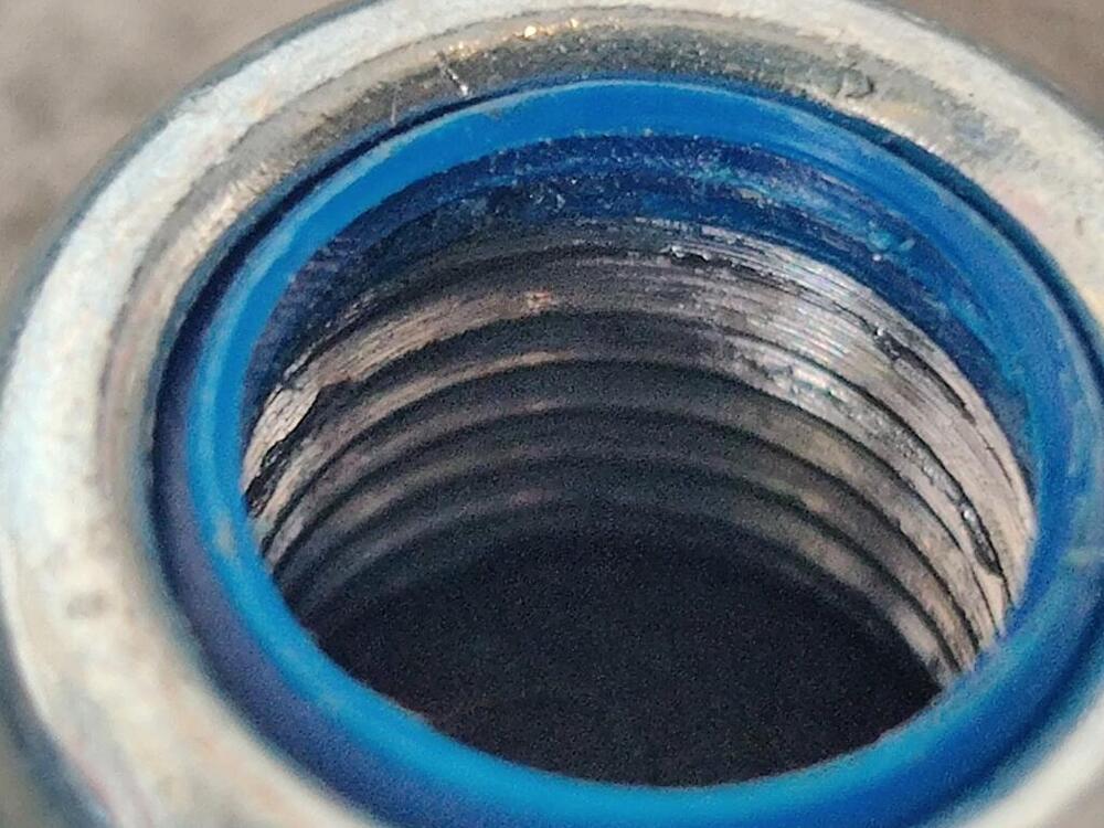
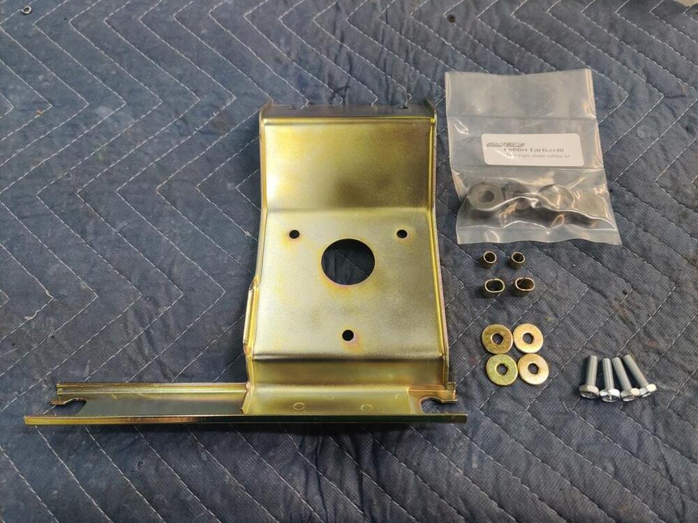
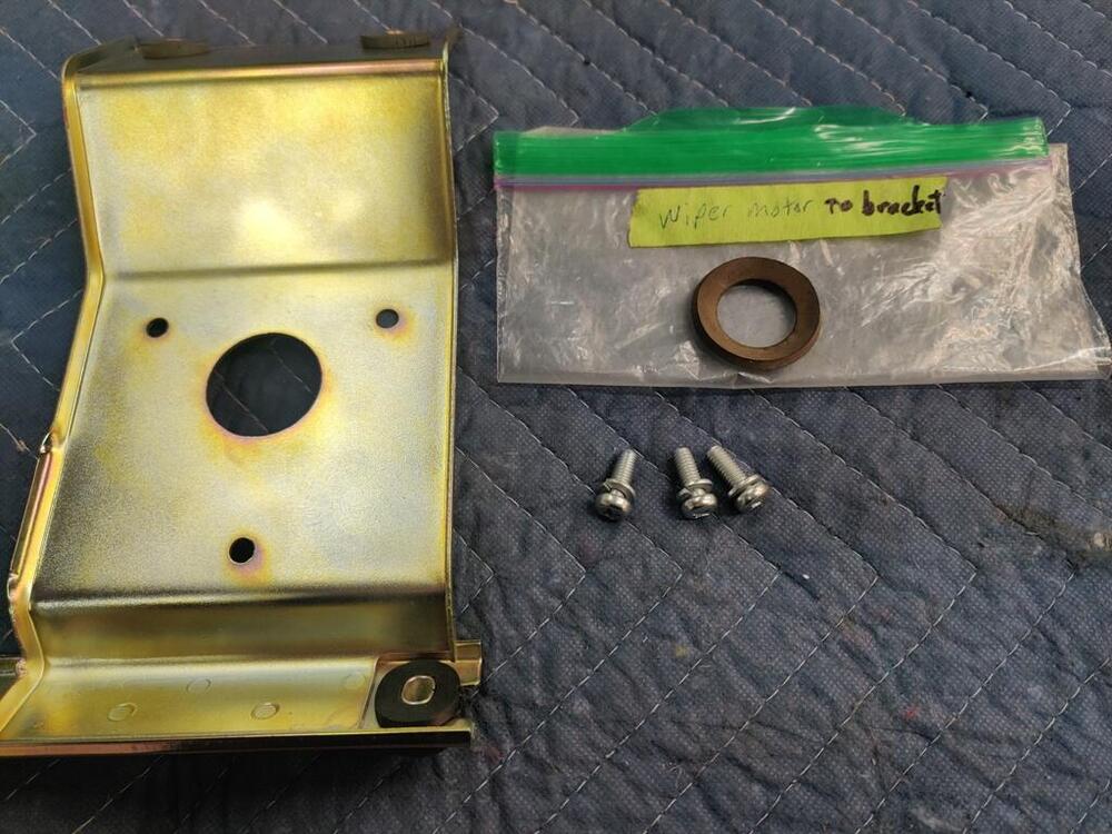
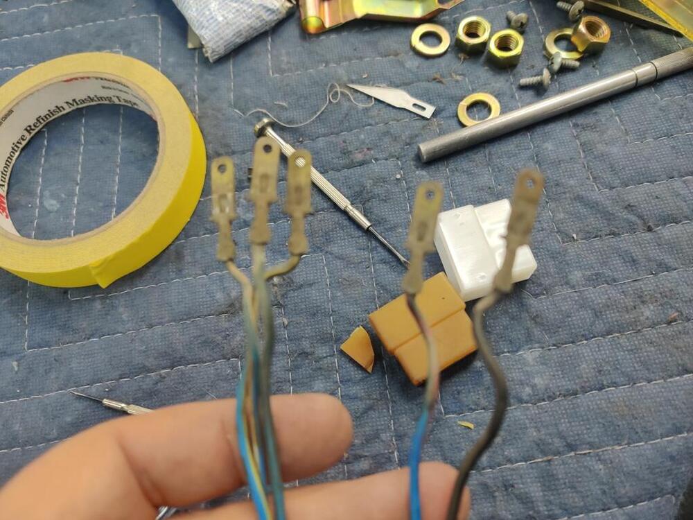
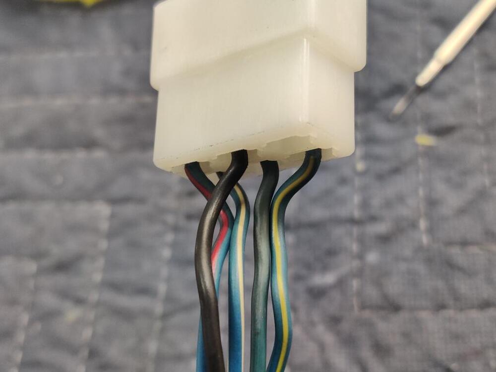
Unfortunately in this instance, the Koni struts I am using have their adjustment done by a nipple at the top of the strut shaft, so no place for an allen wrench there. I get sick when I look at these pictures, but here we go: With this close up, they all look like garbage to me other than the few at the bottom which are not accessed because of the material thickness of the spacer, upper spring perch and upper strut mounts respectively. Come to think of it, I might be able to machine a bit off the spacer to raise the shaft a bit (looks like a quarter inch, to access those good threads at the bottom. If the coupler nut can access all of those, and the garbage ones in the middle, along with the "somewhat still there" at the top, then I might be able to salvage this debacle. The nut doesn't look great, but threads are still mostly there. I have already chase this with a 12M X1.25 tap because I have one. I am waiting on the die to arrive to chase the threads for the shaft. In other news, I gave some attention to the wiper motor, motor mounting bracket, and motor harness tonight. Two of the grommets from 240zrubberparts.com were not as thick as the originals. I chose to use the old ones (just two of four) because there are metal sleeves that go in the center of them. I could have ground the metal sleeves down to match the thickness of the new ones, but my original rubber grommets were in fair condition. So, I used them instead. The original plastic connector was yellowed with age and brittle. So I replaced that. While doing so, I put on the new rubber grommet for the wiring from 240zrubberparts.com I was a bit surprised when I opened up the cover for the wiper motor - It was very clean inside. Being a car from Arizona, and off the road/stored for 28 years in Colorado, I think the motor has seen little use. As I found it: I cleaned the main gear shaft with #000 stainless steel wool, and then lubed the shaft. I probably should do the Honda wiper motor upgrade, but I will see how a fully rebuilt wiper transmission and this motor (with little use) work out first.


-
Not yet. I did come across and interesting tidbit of information. @AZ 240 mentioned in a thread some time ago that "Although I made my own patterns and cut all of my carpet pieces, he was able to surge all of the carpet pieces on his equipment and they turned out great." The problem I have with C and H is from what I can see from pics posted by others, the fit of their latest 240Z efforts doesn't look like it is of the same quality as their carpets from years ago. If doing as Dan did is still an option, I may go that route. But, I am not comfortable with ordering their carpets as is given the somewhat recent photos I have seen.
-
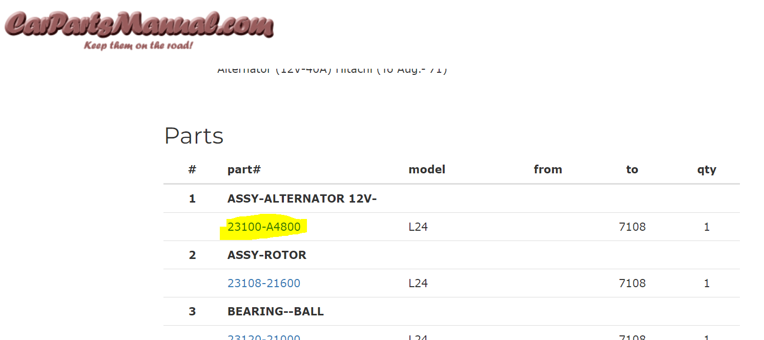
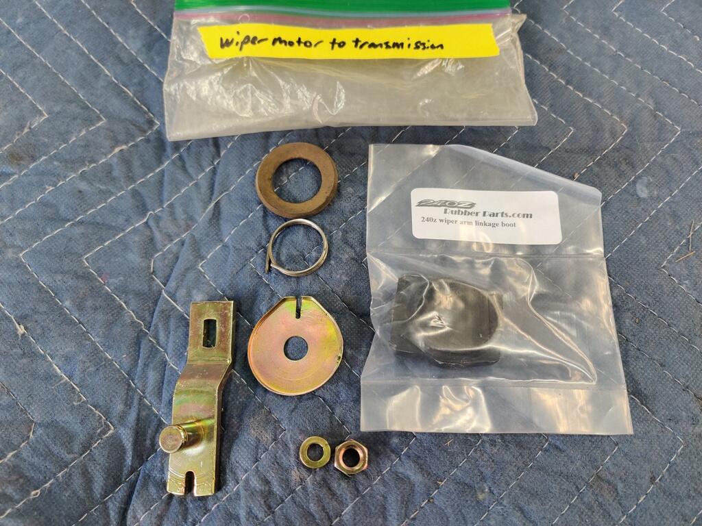
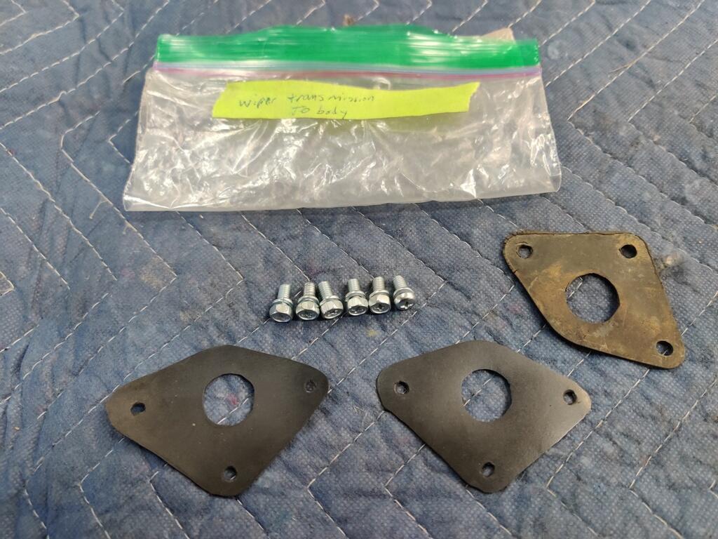
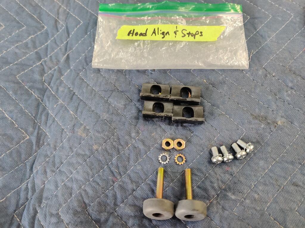
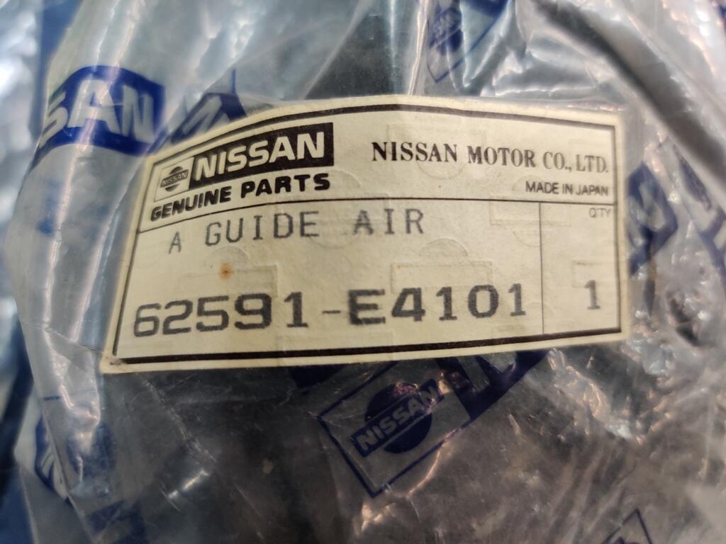
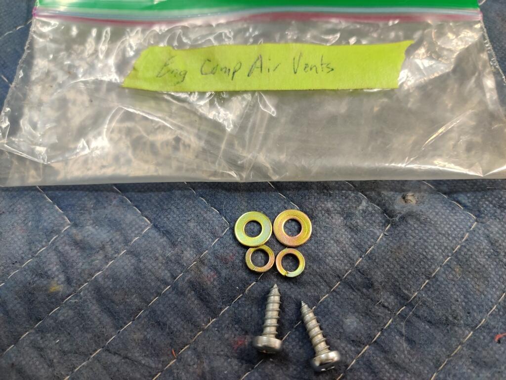
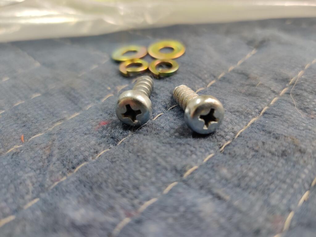
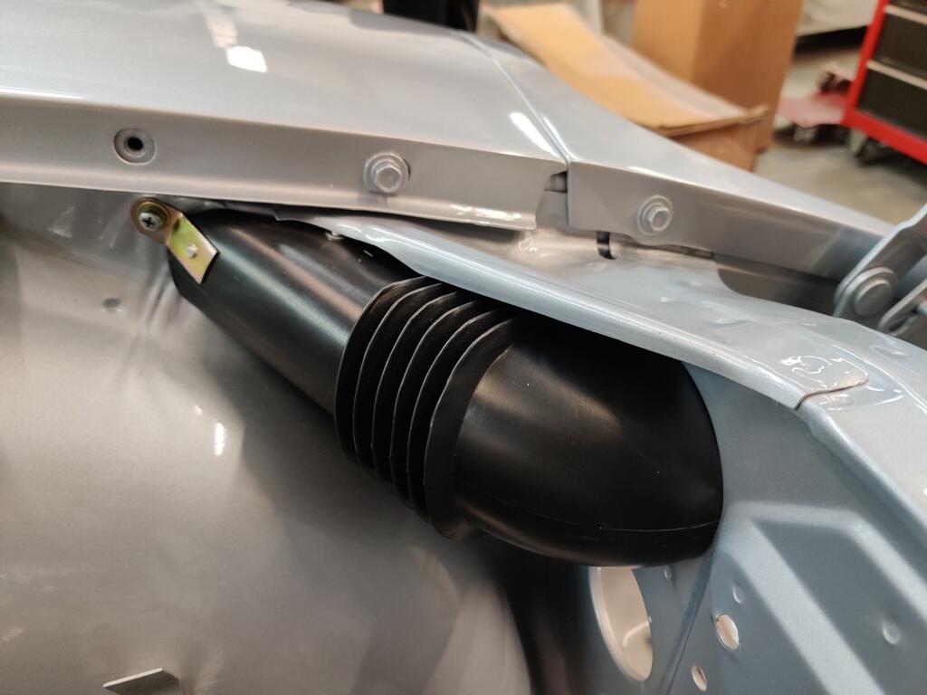
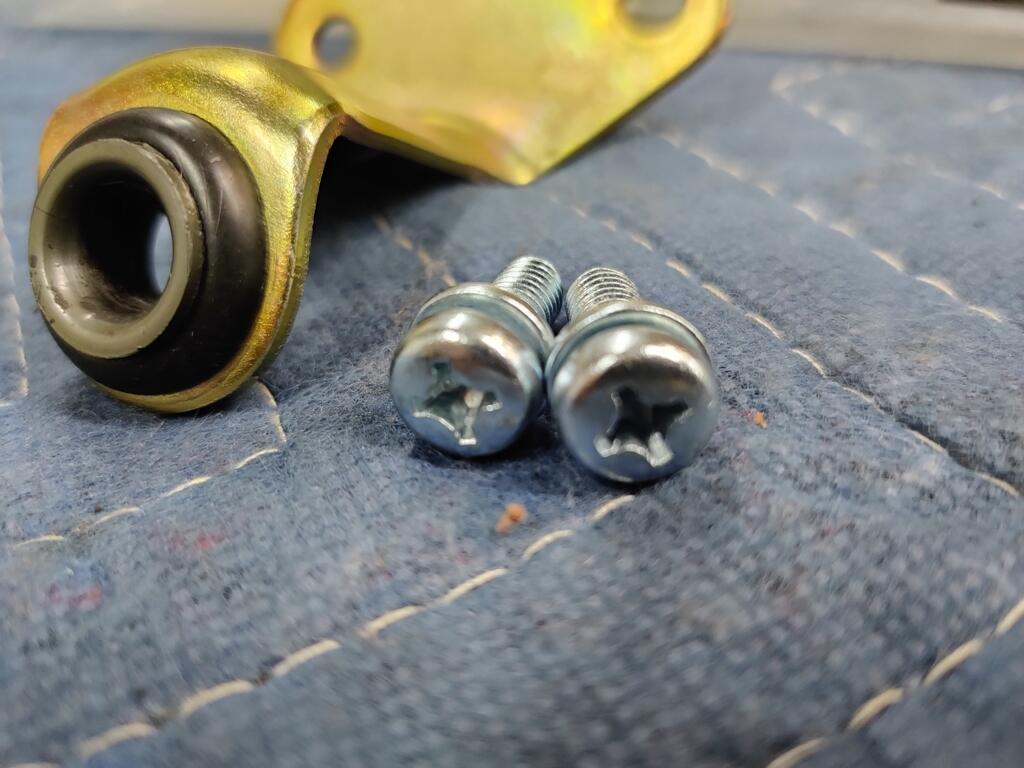
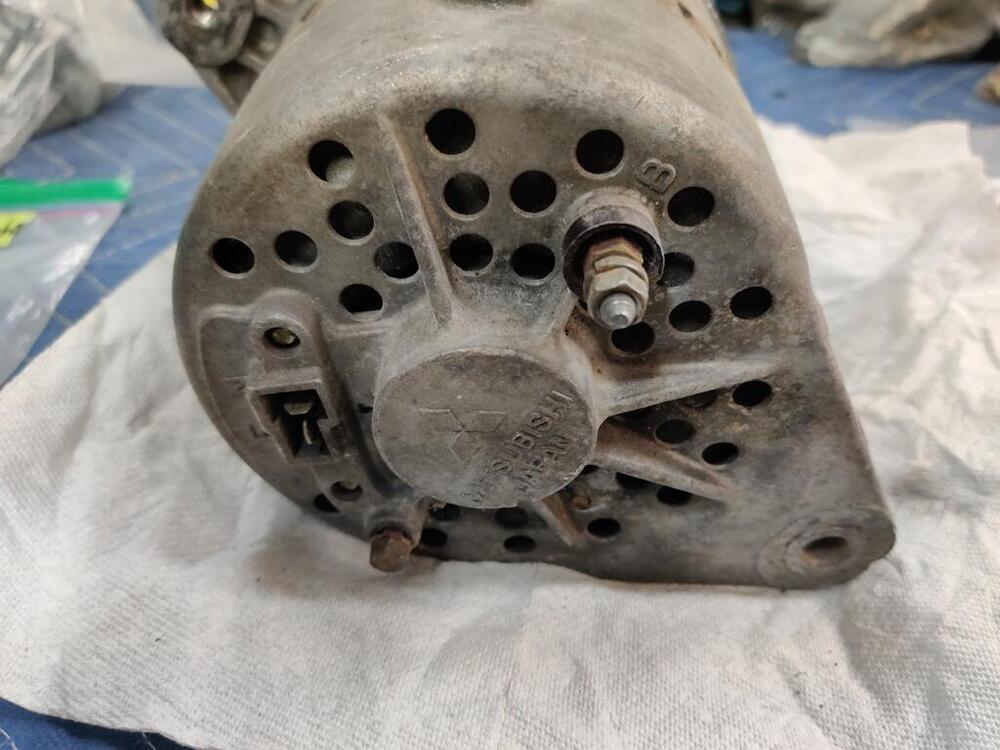
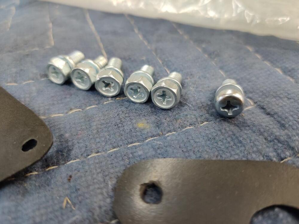
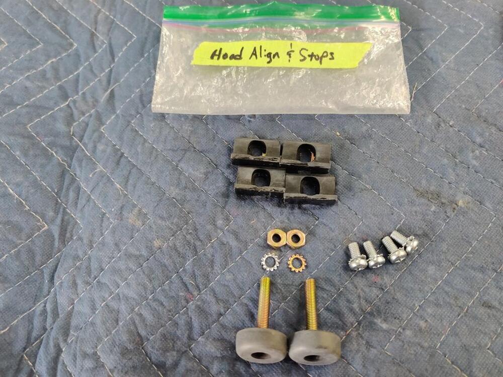
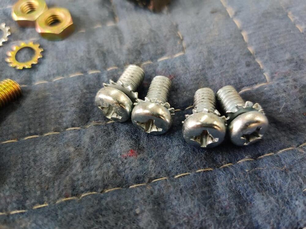
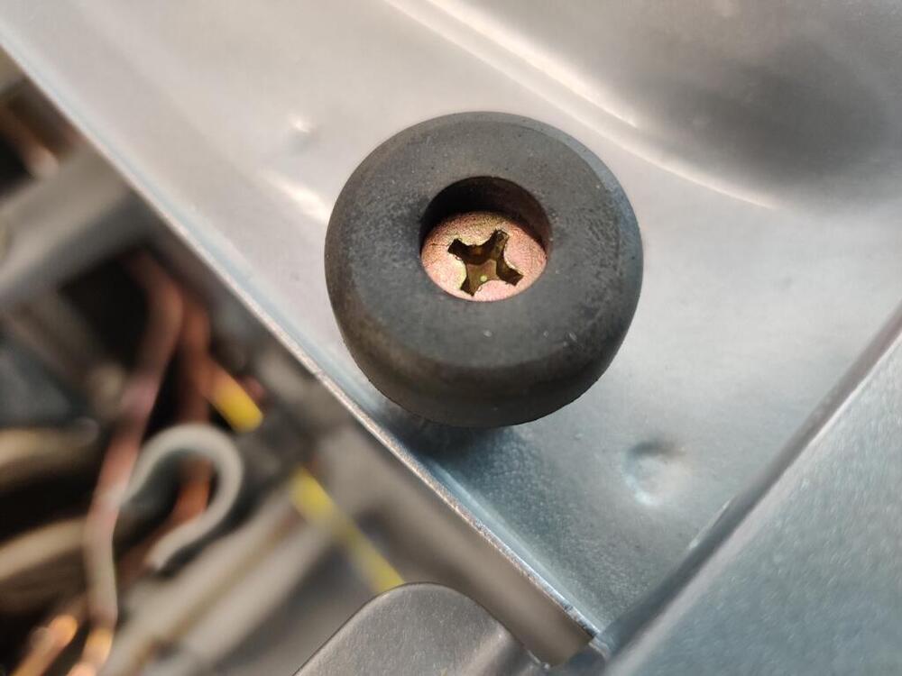
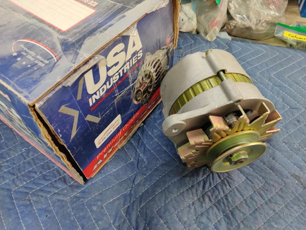
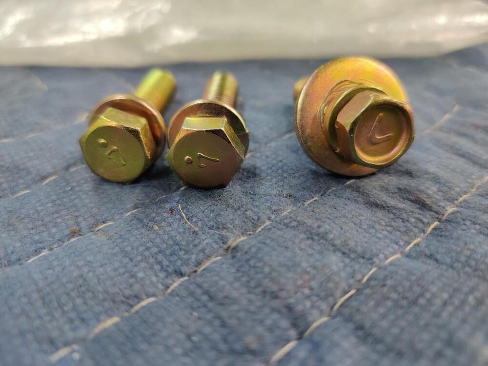
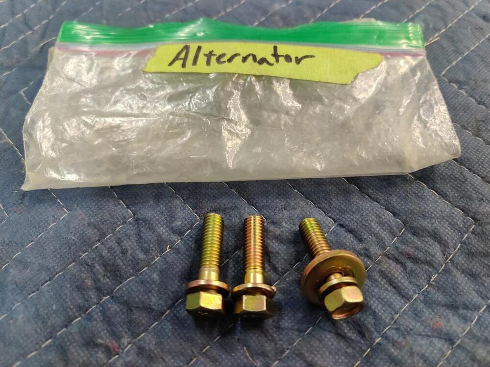
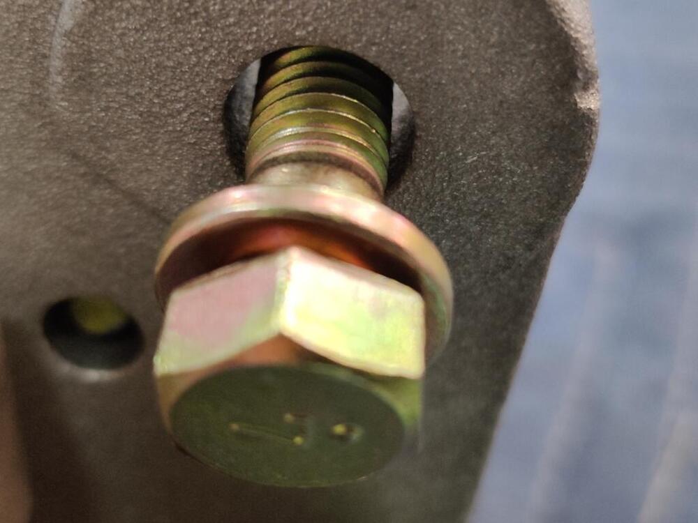
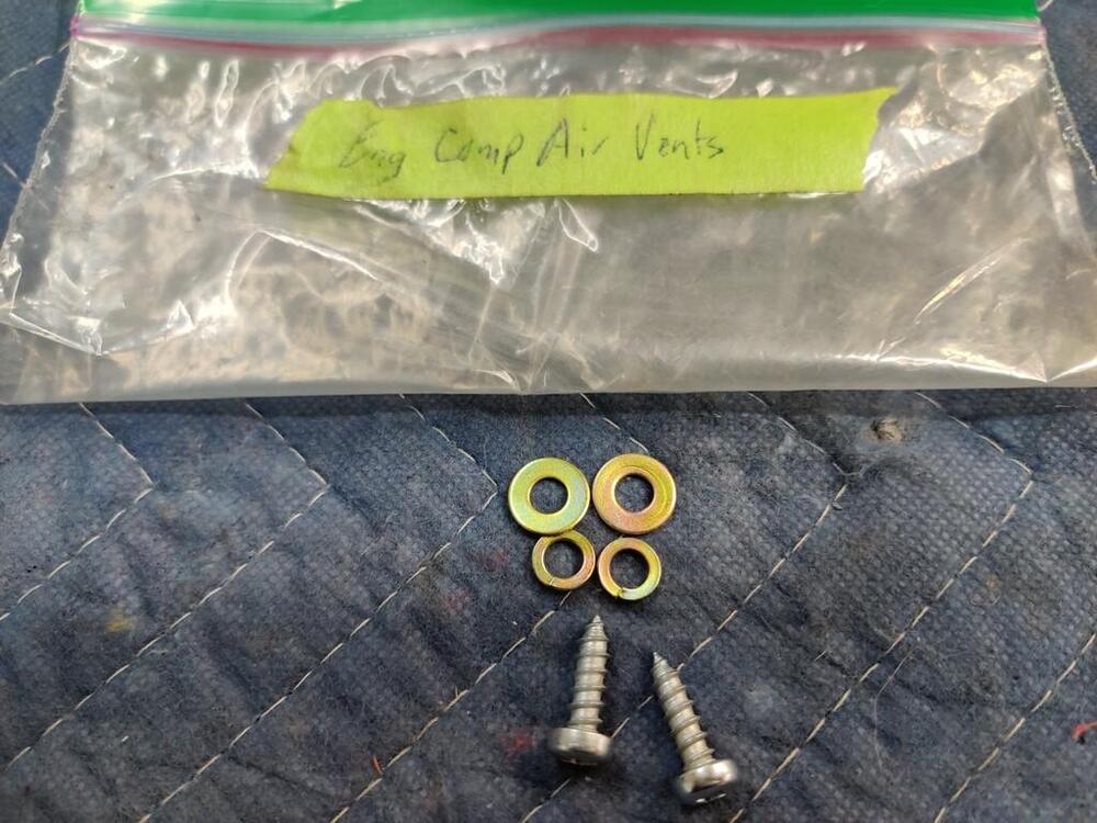
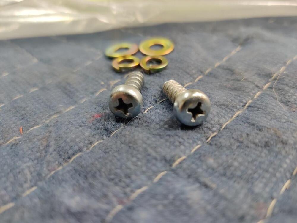
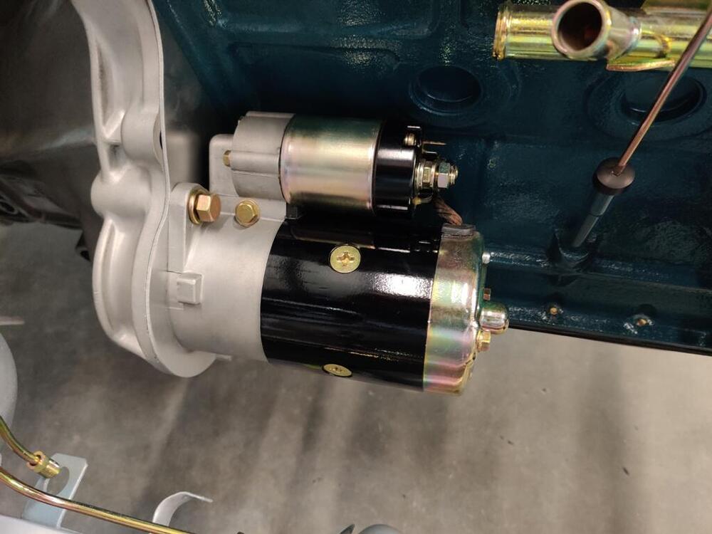
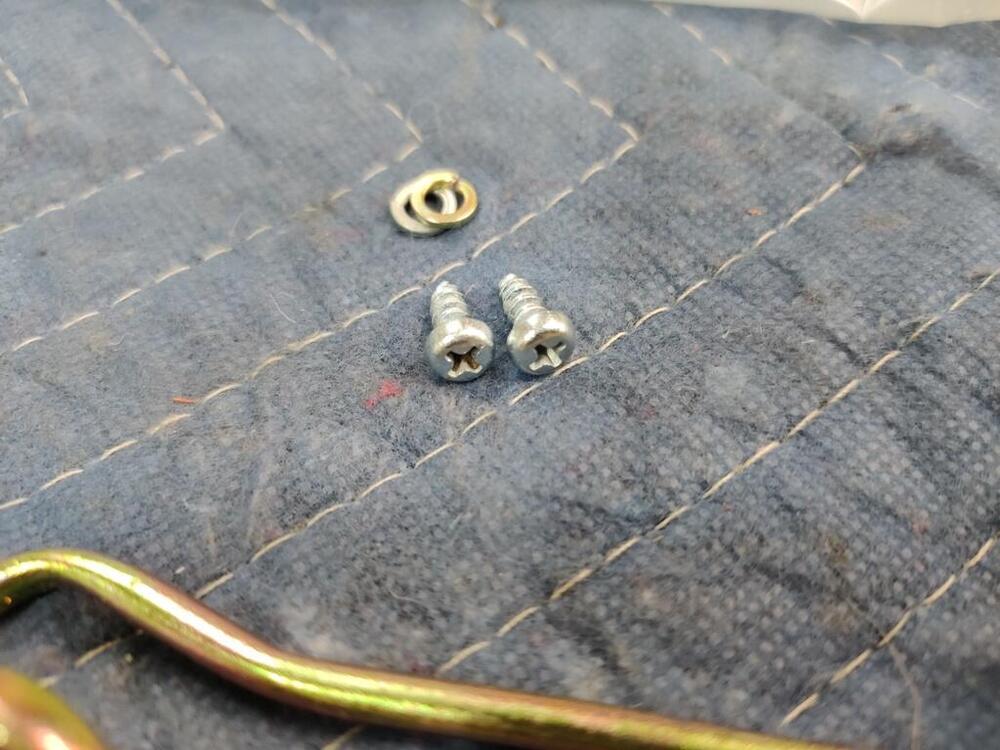
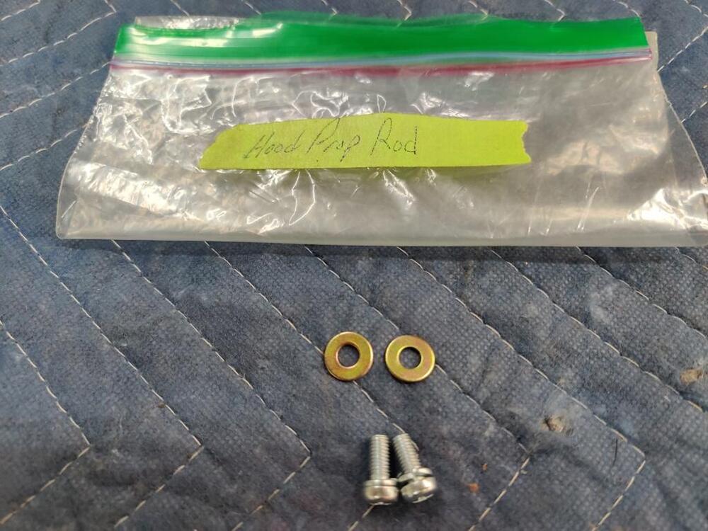
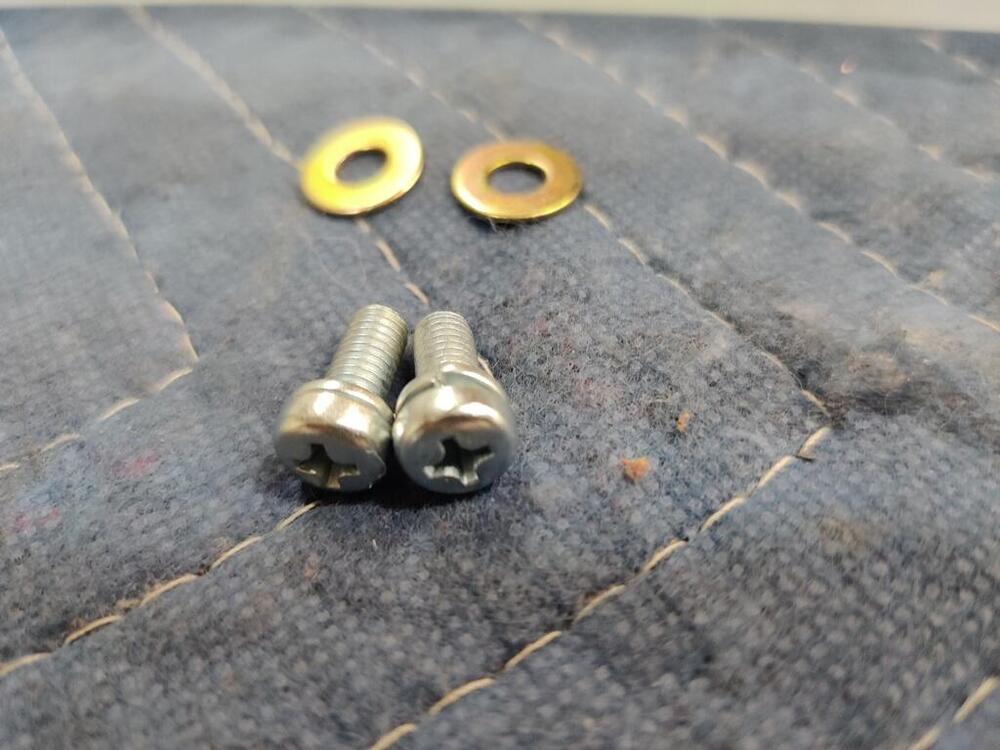
Thank you! Wow. My car came with an alternator just like that one! The part number on it is 23100-U5810. Do you have just one sleeve, or do you have one for each of the lower mounting holes? The hole in the lower mount on mine is a bit smaller diameter than my other alternator, I think. I will have to measure. Is there a chance that this one is original to my 6/71 car? According to the microfiche, this one is original: And that is the rather hard to find "grapefruit" alternator. The one I bought for $39 is part number 23100-U5800. It seems there are a lot of Nissan alternator part numbers. I continued today with some more assembly. Little things here and there, and I assembled the wiper "transmission". Note that one of the bolts for attaching the transmission to the body was a pan head instead of hex. I came across a thread one time that pointed out the same for another. It is possible that this bolt has a slightly smaller head to keep from hitting on the cow panel. The finished product: Note that the hood stop bolts have a very unusual thread pitch. New replacements are still available from Nissan at this time, however the bolts have the wrong thread pitch for the 240Z. I purchased new ones from Nissan and swapped the rubber portion over to the original, re-plated bolts. Also, sadly... I over torqued and stripped the threads on one of the front Koni strut inserts. I don't know what happened. I was being extremely careful. For each of the struts, I secured the assembled strut to the chassis. For the rears, there was not problem. I set my new(ish) electronic torque wrench to 37.5 ft-lbs. I went slowly and did not have issues. When the modified by Motorsport gland nuts were delivered a week or so ago, I assembled the front struts, and bolted them to the chassis as I did for the rears. When I went to torque the top nut on the driver side, my belief is that the torque wrench malfunctioned. As I was tightening, the nut got tighter, but the wrench did not make an audible, or vibrate (which it does as it gets closer to the specified torque setting). At one point, feeling that it was notably tight, I removed the torque wrench and checked the setting on the display. Still 37.5. Then attempted to tighten one more time. At that point the nut started feeling funny - like I had stripped the threads. So, I tried to remove the nut, but then the strut shaft started spinning round and round. The flat part or "D" of the upper strut isolater stopped keeping the strut shaft from spinning. FFFFFFFFFF*****************! I stopped and did something else because I wasn't mentally prepared to continue with the situation. Only a few days ago did I remove the strut from the car, put it on the bench and proceed to spend many hours trying all manner of ways to clamp the strut shaft to keep it from spinning as I attempted to remove the shaft nut. What a pain! Anyway, the ONLY way to get the nut off was to make some wood board/strips, bore a hole with a hole saw (half of the hole on one and half on the other) in them to match the diameter of the shaft, and clamp the wood around a rubber sheet which gripped to the shaft. I had to use a C clamp to squeeze all that together to get sufficient grip on the shaft. Sorry, I don't have pics. AND, I had to use an impact gun to back the nut off, as using a socket wrench by hand, I could not keep the strut shaft from turning I'd still be at it if I didn't resort to an impact gun. Anyway, I am fairly screwed with this one shock. I have about 4 to 5 threads that are good - at the very top of the threaded portion. I will take pics and share them. In the meantime, I have a M12 X 1.25 die coming. I am going to chase the threads and see what I have. I have a little hope that I can salvage the situation. If the threads clean up a bit, and I can effectively utilize something called a coupling nut, which is essentially very tall nut that can engage the good threads at the top, I may be able to avoid having to buy another strut insert.


-
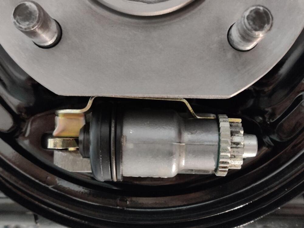
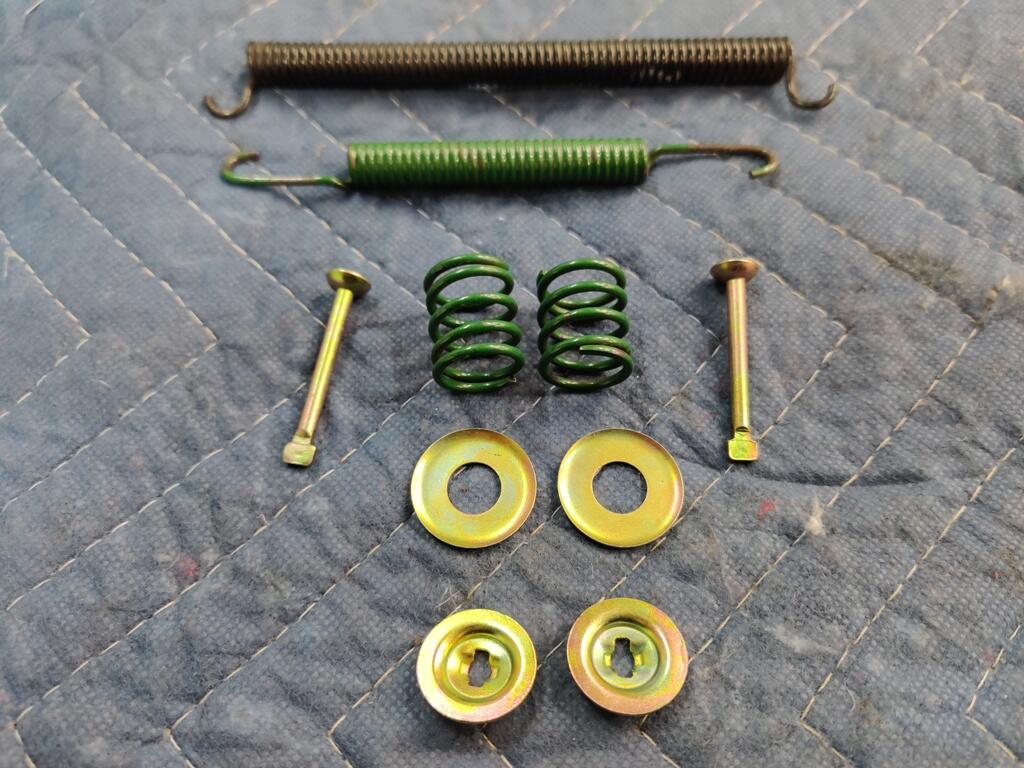
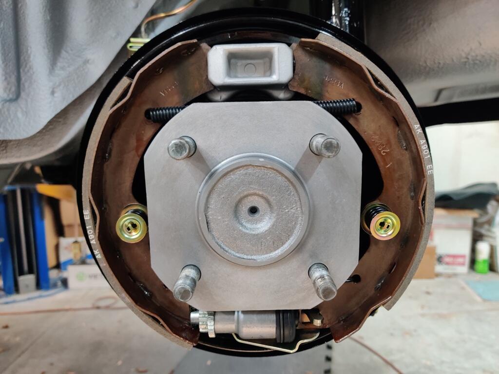
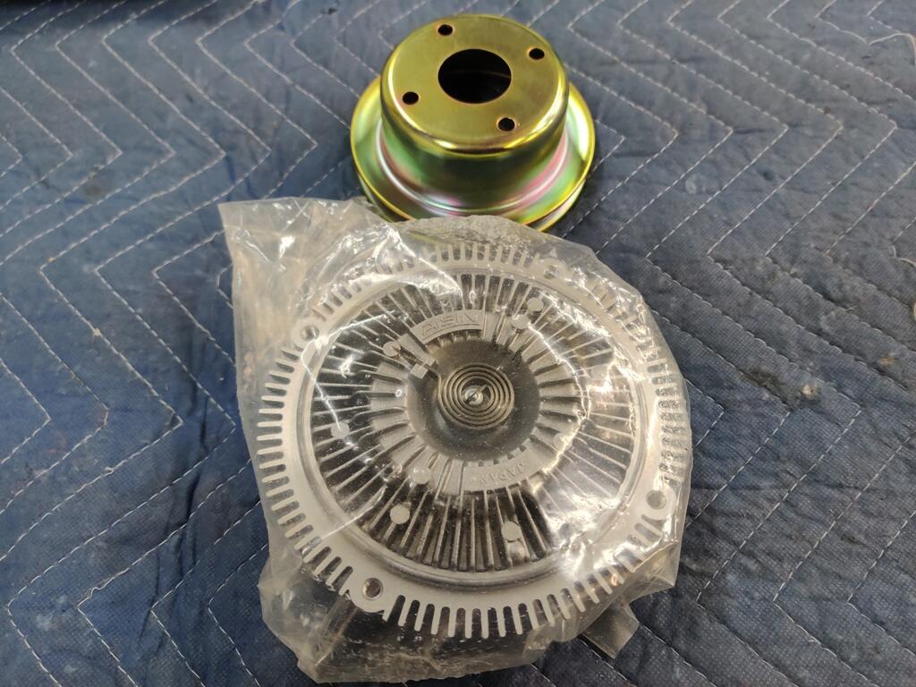
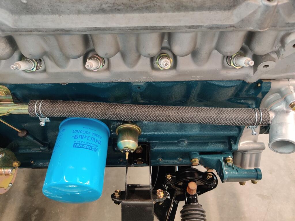
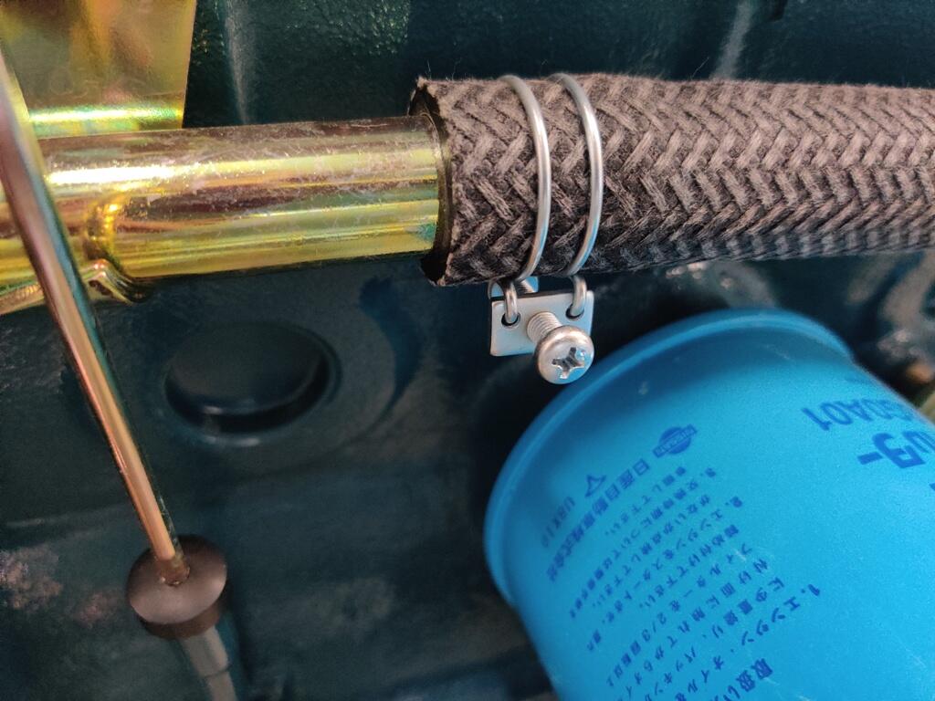
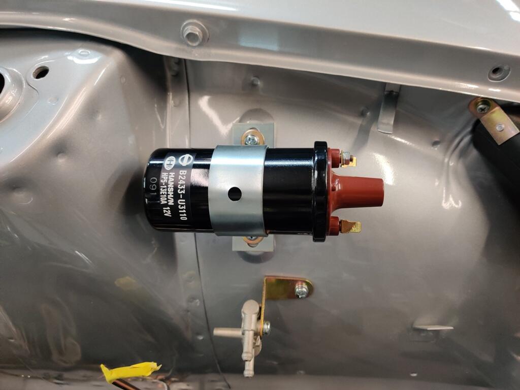
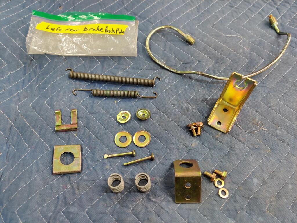
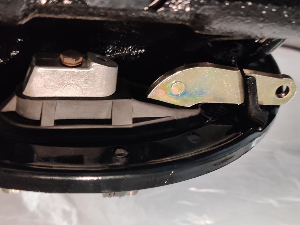
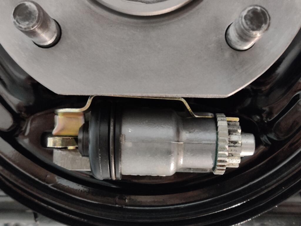
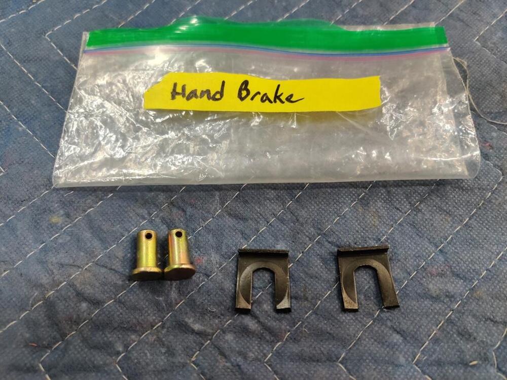
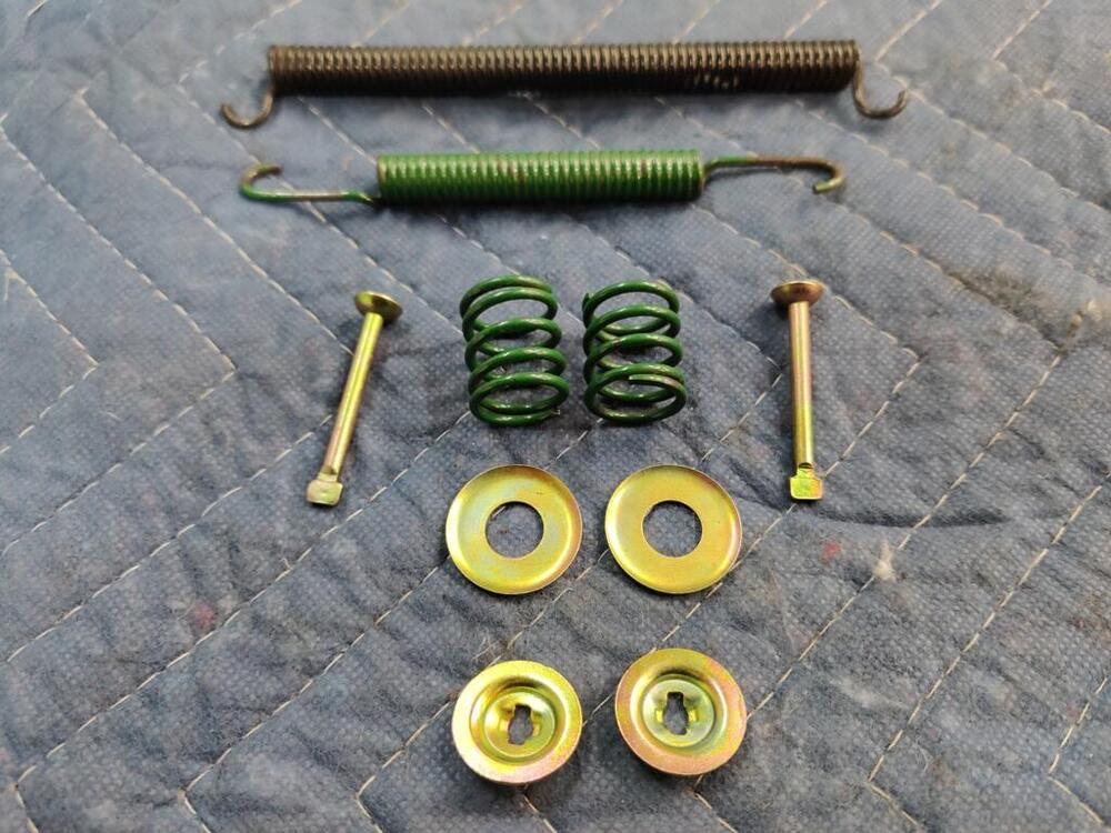
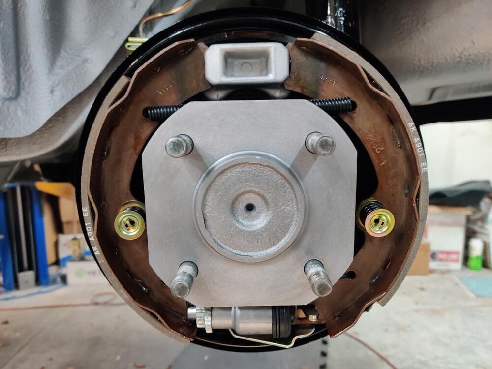
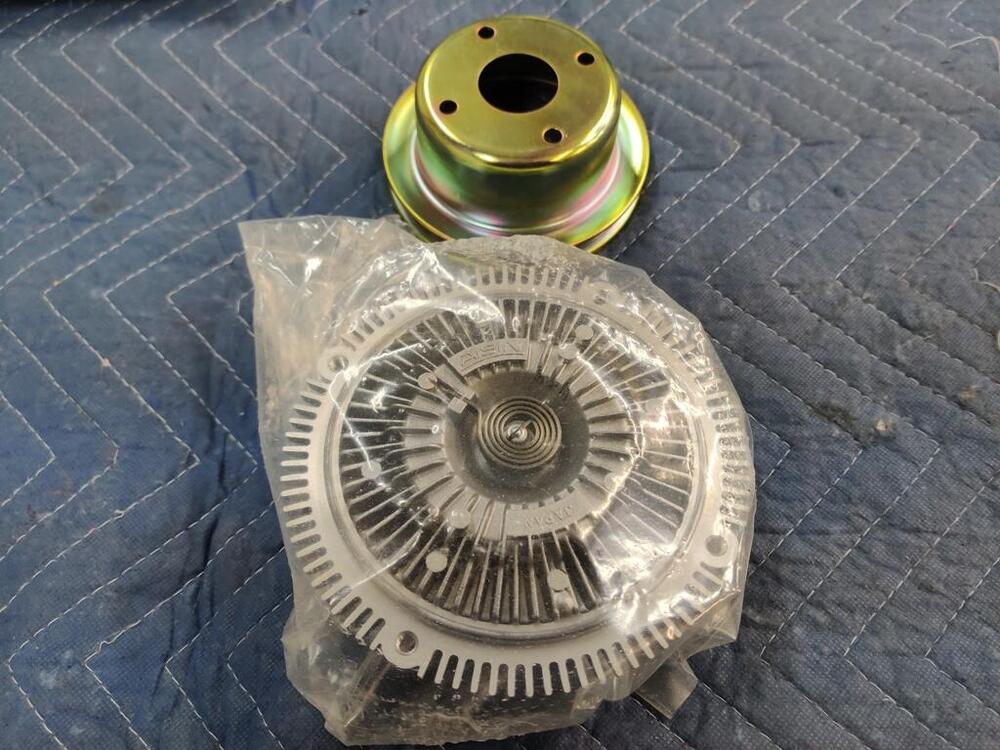
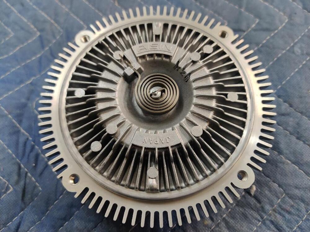
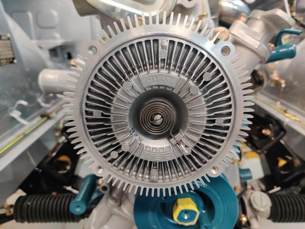
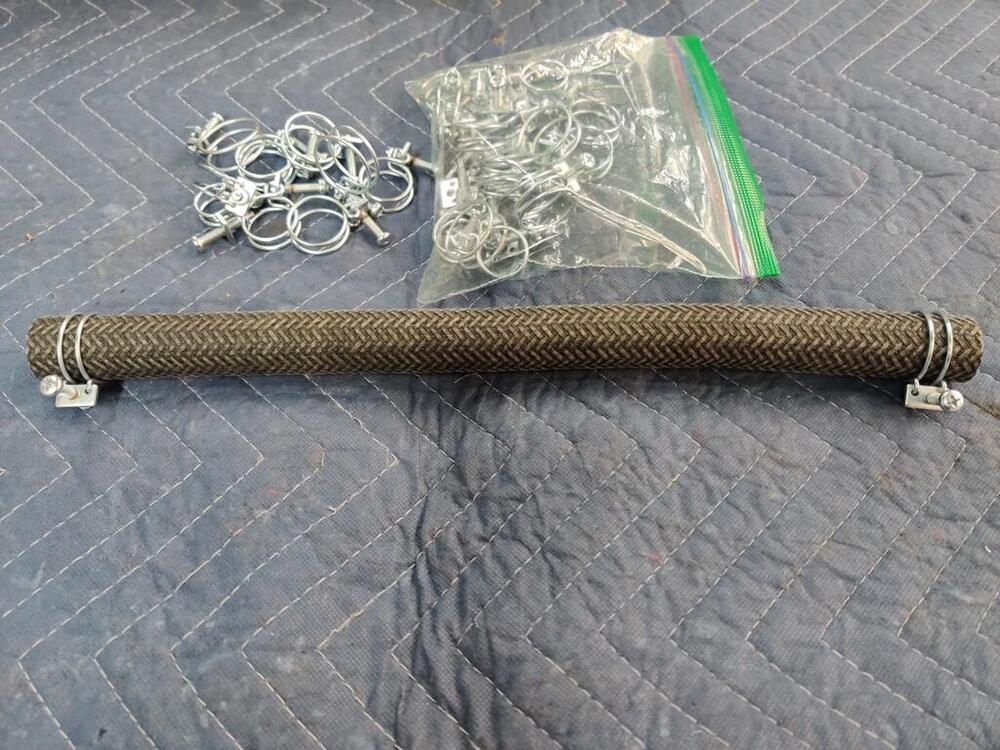
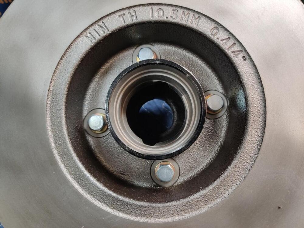
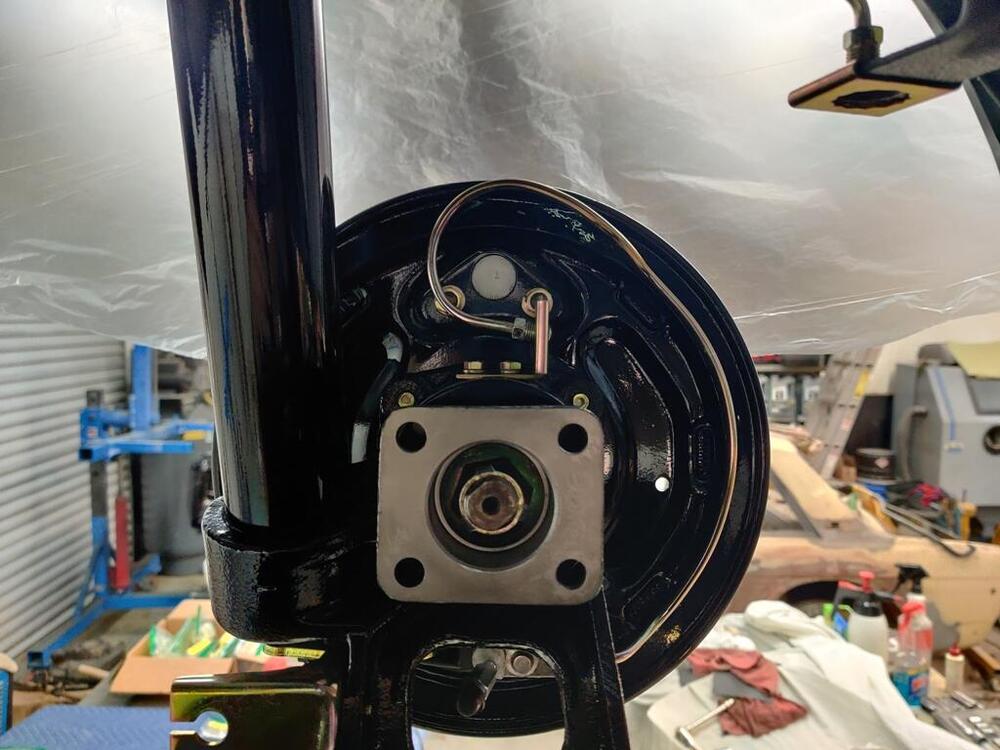
Yep, I figure it only takes about a minute to document those before I bolt a part on and it can be a reference for others! I have continued with assembly in various areas on the car. I received the NOS brakes shoes, so I went about putting those on today. I found that I installed the levers for the handbrake functionality incorrectly, and had to take the wheel cylinders back off to swap the levers to the opposite sides. Would have been nice if instead of both having "R" on them, one had an "L" instead. I would not have mixed them up if that had been the case. Re-plated brake hardware, and new brake hoses: I find that putting silicone rubber around the circumference of the hub where the drum indexes is effective at keeping any water from finding its way into the rear brakes. Doing this is effective at stopping rust from seizing the drum to the hub "ring" and hub surface. I could use some help with a couple of questions I have about my alternator. First, I am nearly certain that these bolts are not the original alternator hardware. Does anyone have info on the original bolts and washers? Secondly, this was one of the first parts I think I acquired after getting the car. It was only $39, and I thought, "what a deal!" I went to mount it on the engine today and I noticed that, although the bolts are the right size for the alternator bracket, the lower holes in the alternator case are much bigger in diameter than the bolts. I believe there are some sleeves which are typically pressed into place and they are perhaps missing? Also, I kind of doubt this rebuild is high quality, but I couldn't find a "grapefruit" alternator... and don't know if my VIN should have one for sure either. So, this one will have to do for now. For the cooling fan, I was successful in obtaining an early metal type with original clutch assembly in good condition. However, I will be installing a plastic fan instead. I purchased an Aisin clutch and installed that and the pulley today. I also installed the first of the cloth braided hoses today. I think it was almost $900 for 11 hoses. I sent off many original hose clamps to be re-plated. Hopefully, I have all the ones that I need for the whole car. Oh, I wanted to mention... if any of you see that I have assembled something incorrectly, or am using the incorrect part for a 6/71 240z, or anything is "off" from what you believe to be original, please say something. I'd rather know about it than not. G


-
Ditto. It would be awesome to have access to that little sand blaster, the lathes, sheet metal brake, Beverly shear, etc.
-
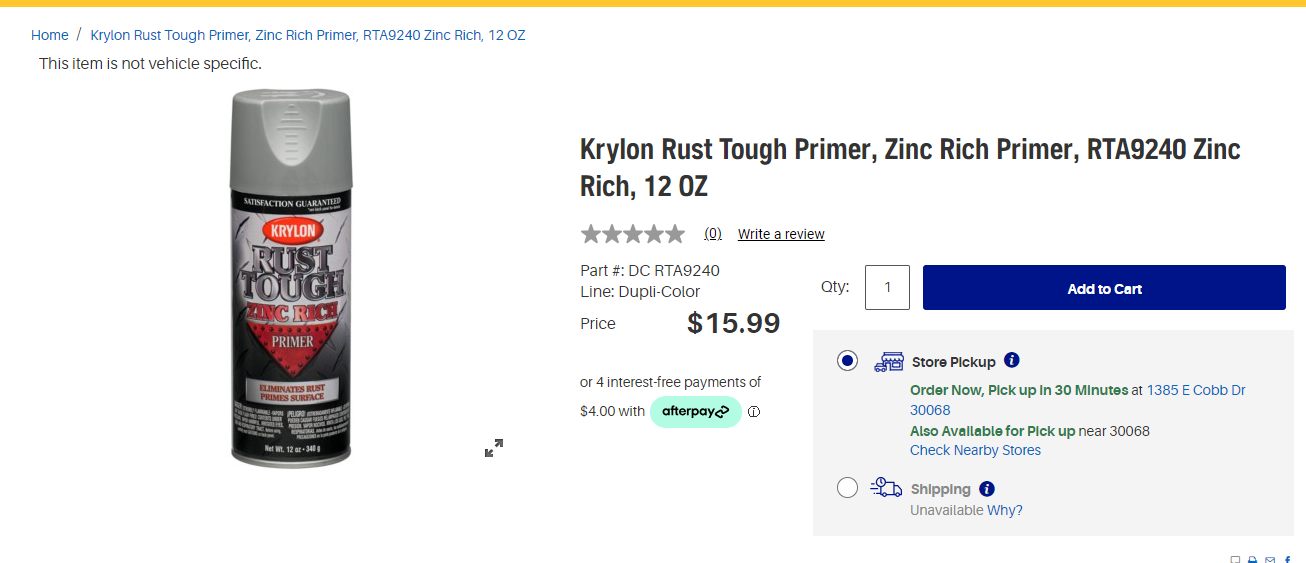
While a primer only, this would be better than bare, and to my eye, looks like the factory finish. Maybe buy a can, and if you don't use it for the calipers, ultimately, it is a very good primer.

-
I started looking at my original firewall insulation, and unfortunately, one of the three pieces (right side) is in rather poor condition. I found myself searching for options, looking at what others have done. I found a few posts about the carpet snaps/posts, but not much about anyone who has found suitable materials to reproduce the look of the factory firewall insulation. I like the look of mass loaded vinyl in pictures I have seen, such as this: https://www.ebay.com/itm/373136954065 I have found by reading descriptions that "1 lb" mass loaded vinyl equates to 1/8" thickness. I think that is close to what the original material thickness is. The description for this particular item says "For automotive applications, use a decoupling layer of jute or closed cell foam." Anyone have experience with using materials that they would recommend?

-
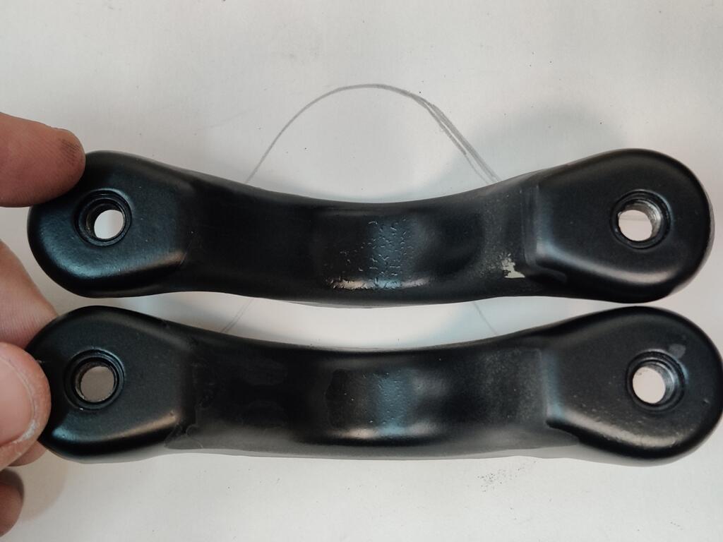
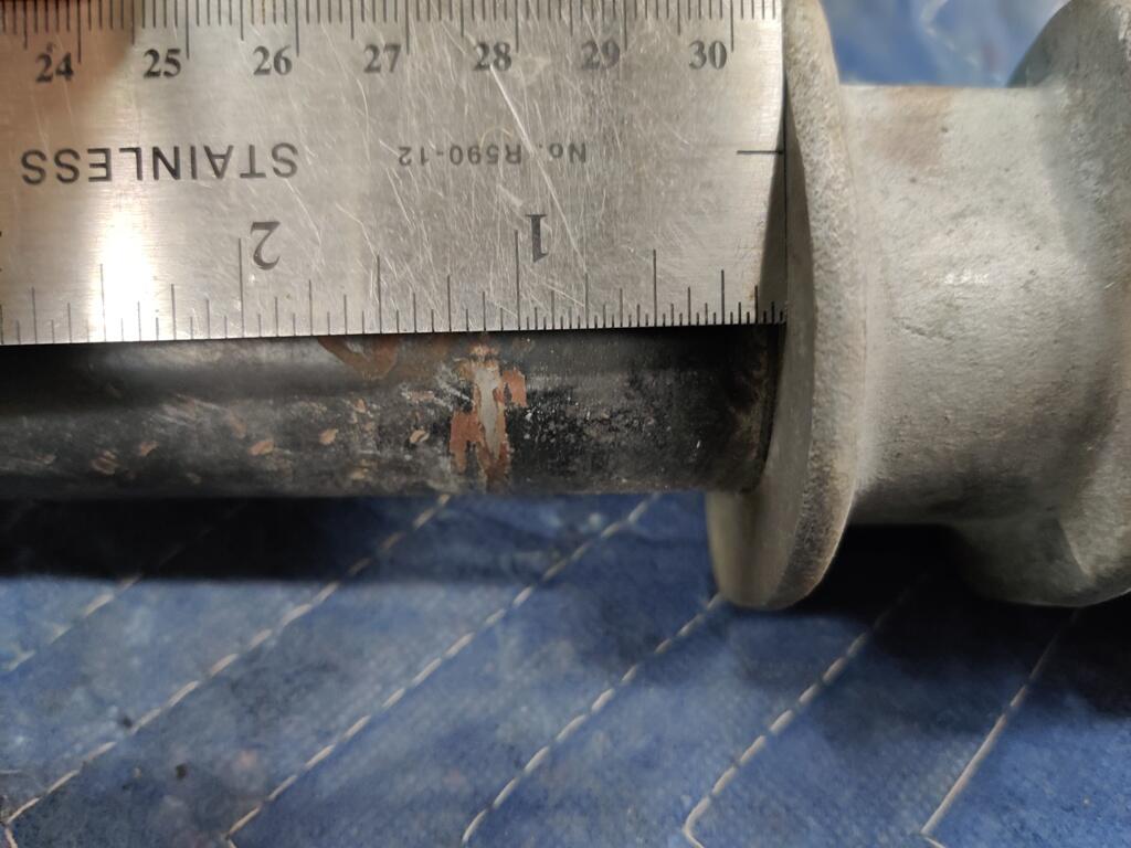
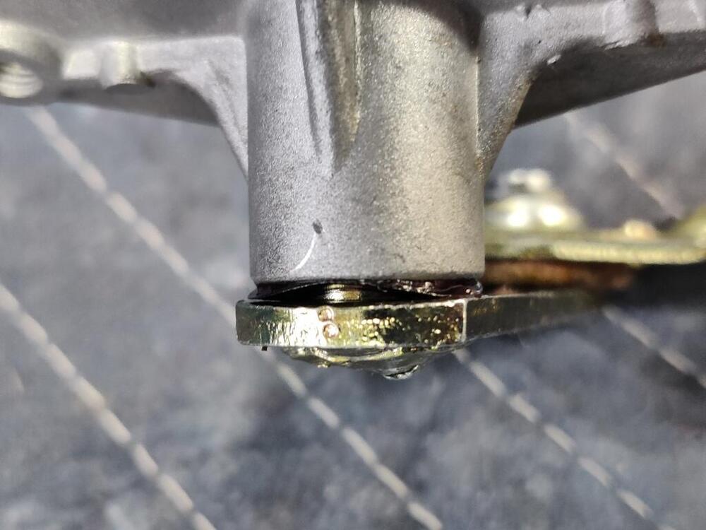
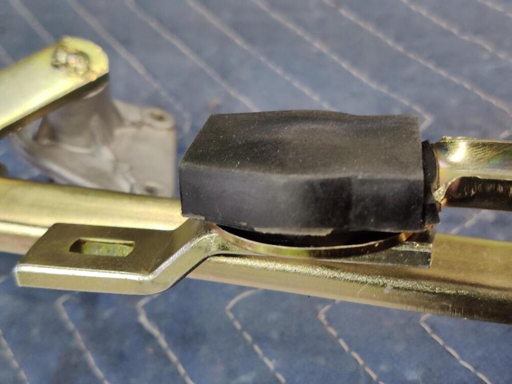
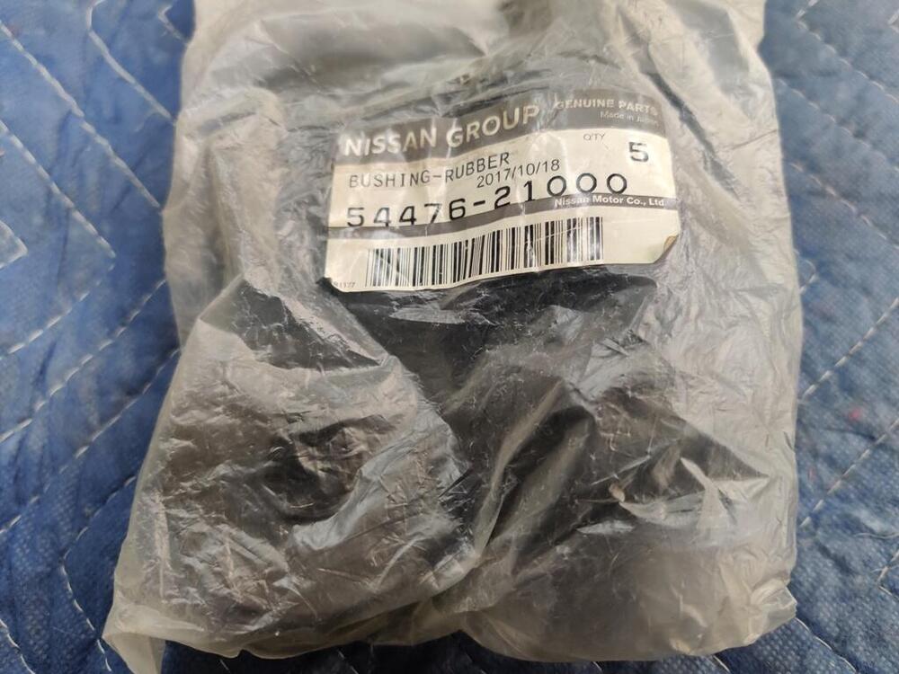
The parts you are looking to remove will slip off, but are easier to remove if you unscrew them. It has a bonded rubber layer on the inner diameter, and from its position on the rack, the threads on the end of the rack imprint on the rubber. If I recall correctly, I slide it a bit toward the end of the rack until it hangs on the threads, and then unscrew it the rest of the way.
-
Nice. Thanks for sharing. I've started thinking about buffing stainless items, as my project is getting to the stage where they will need to go back on the car.
-
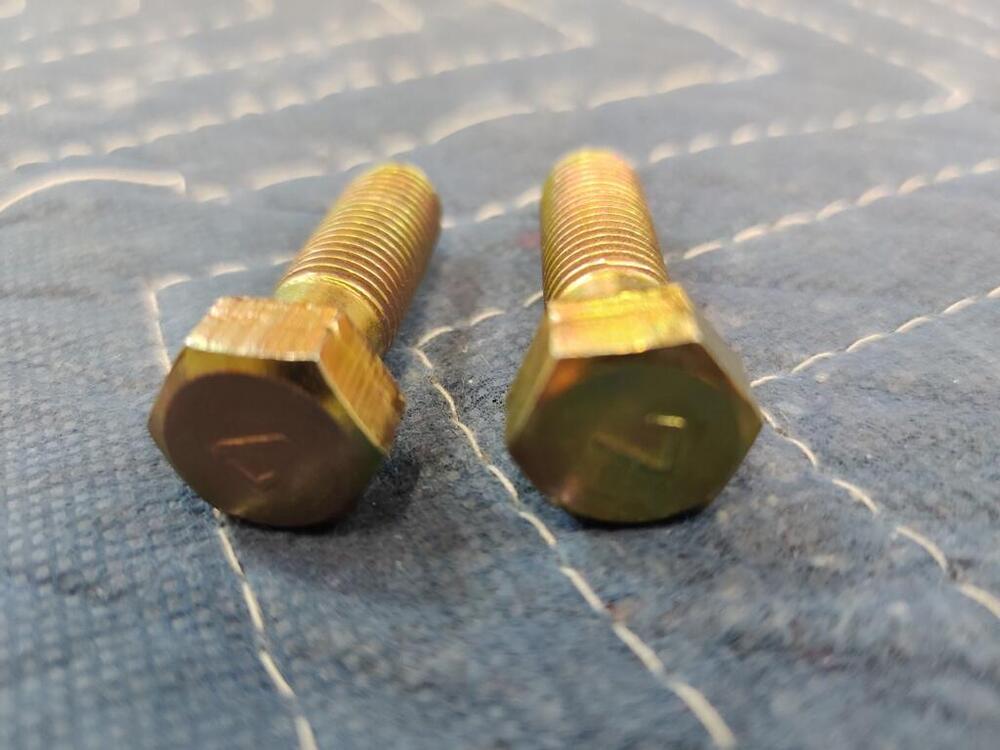
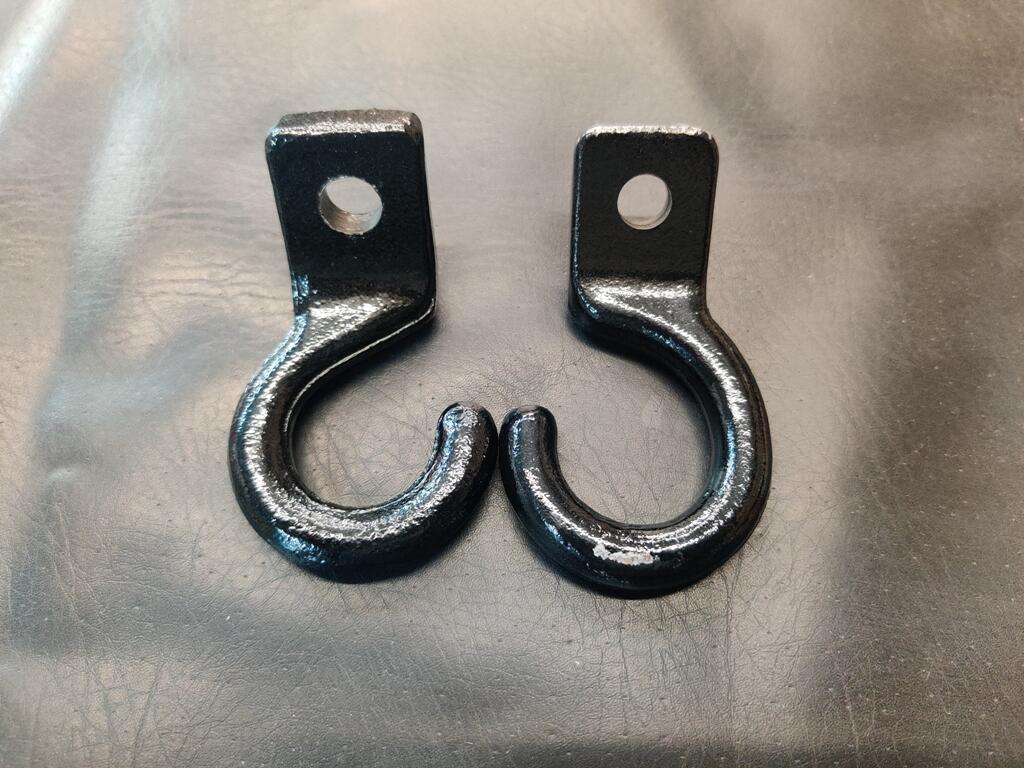
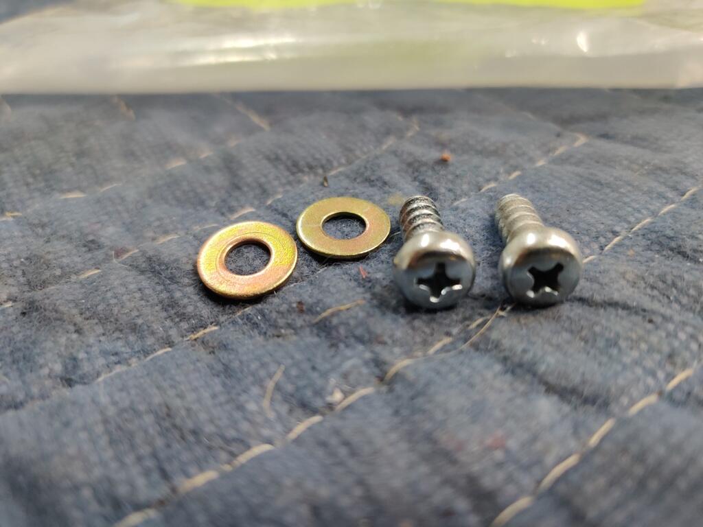
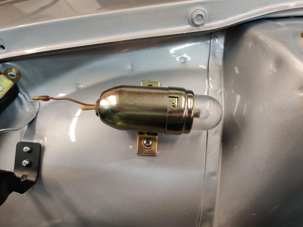
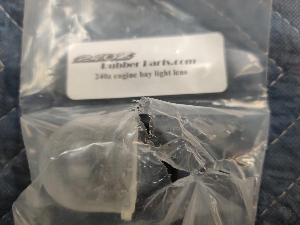
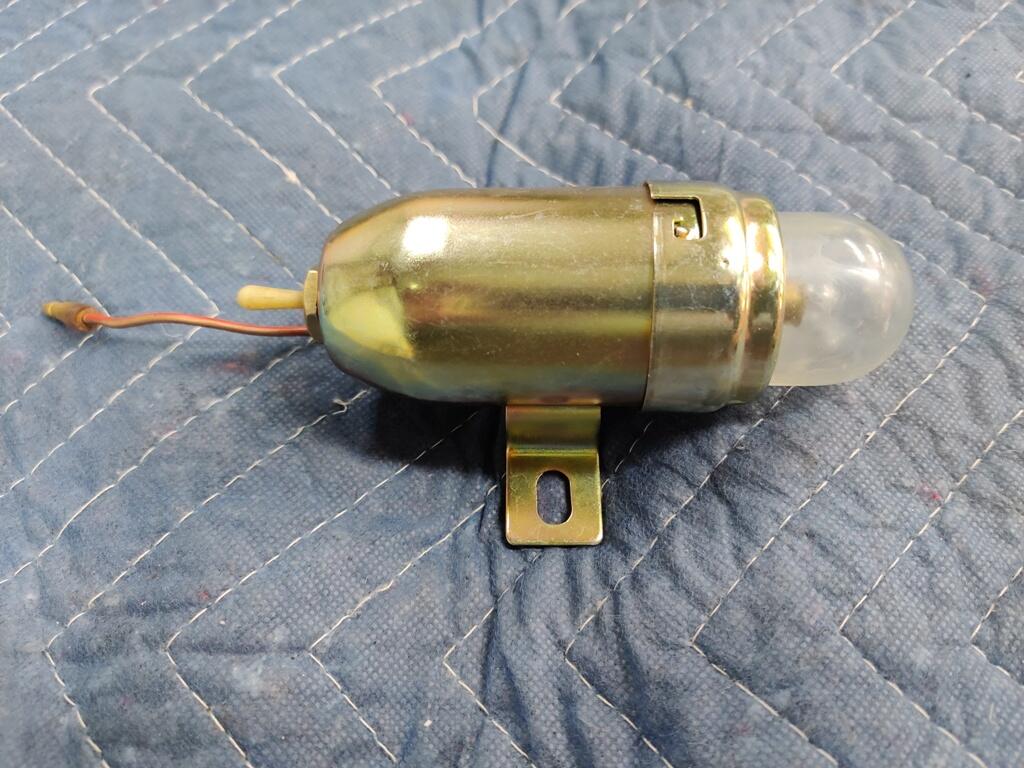
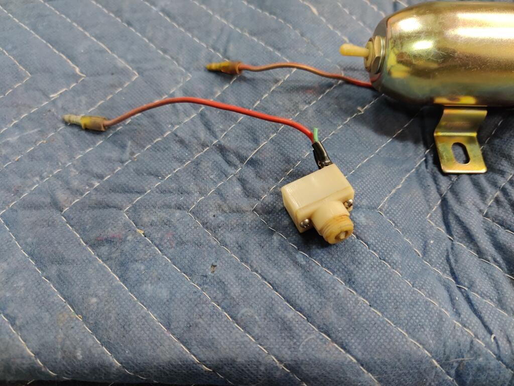
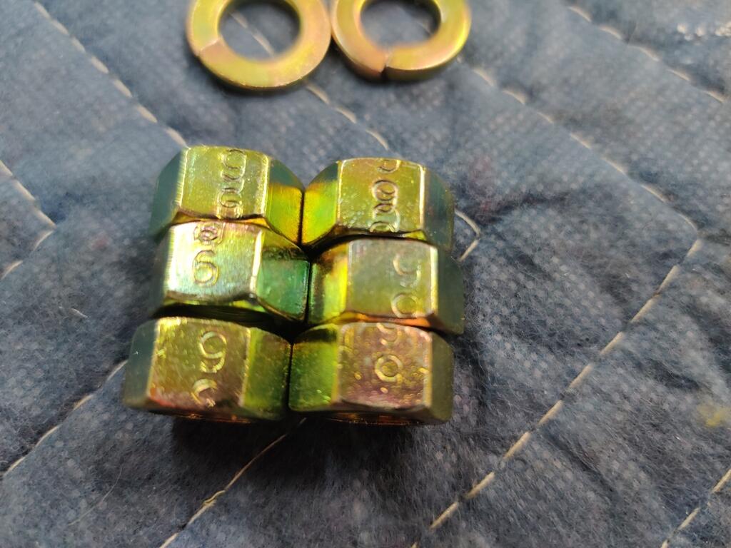
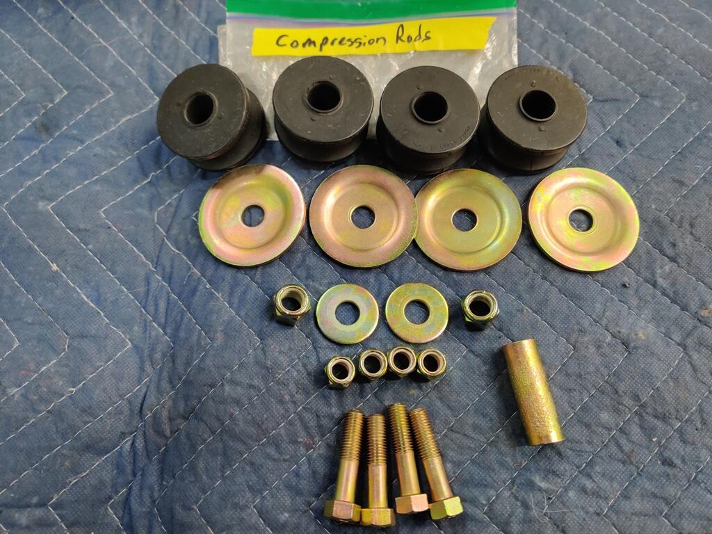
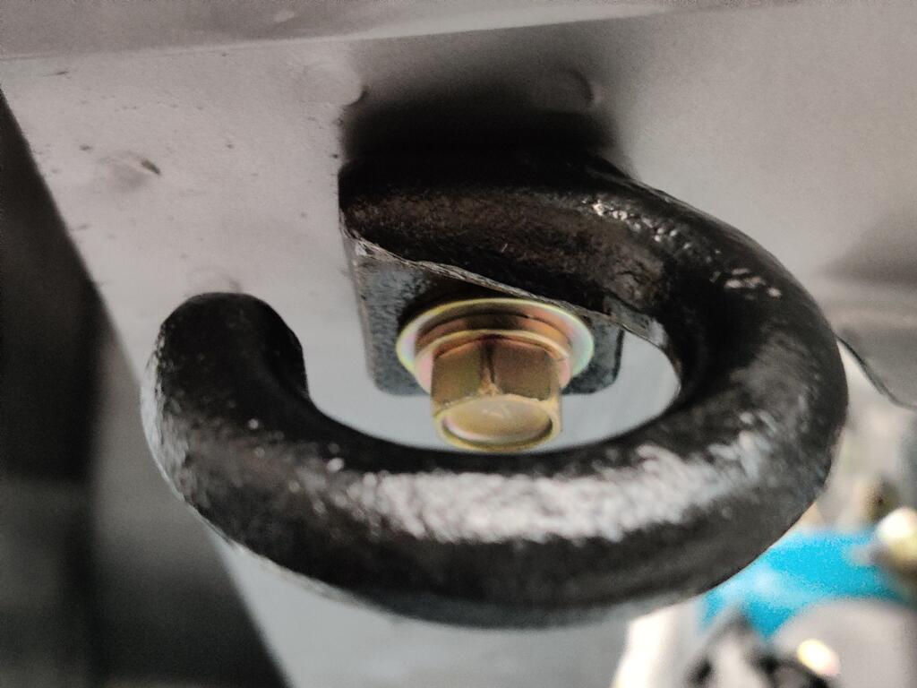
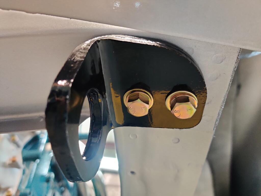
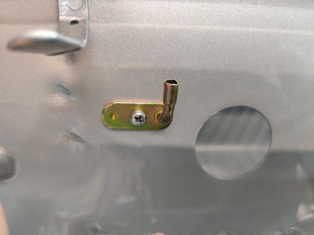
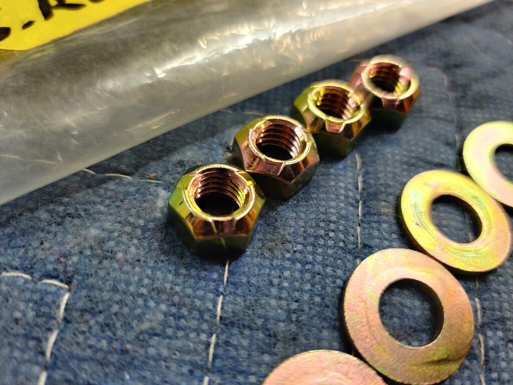
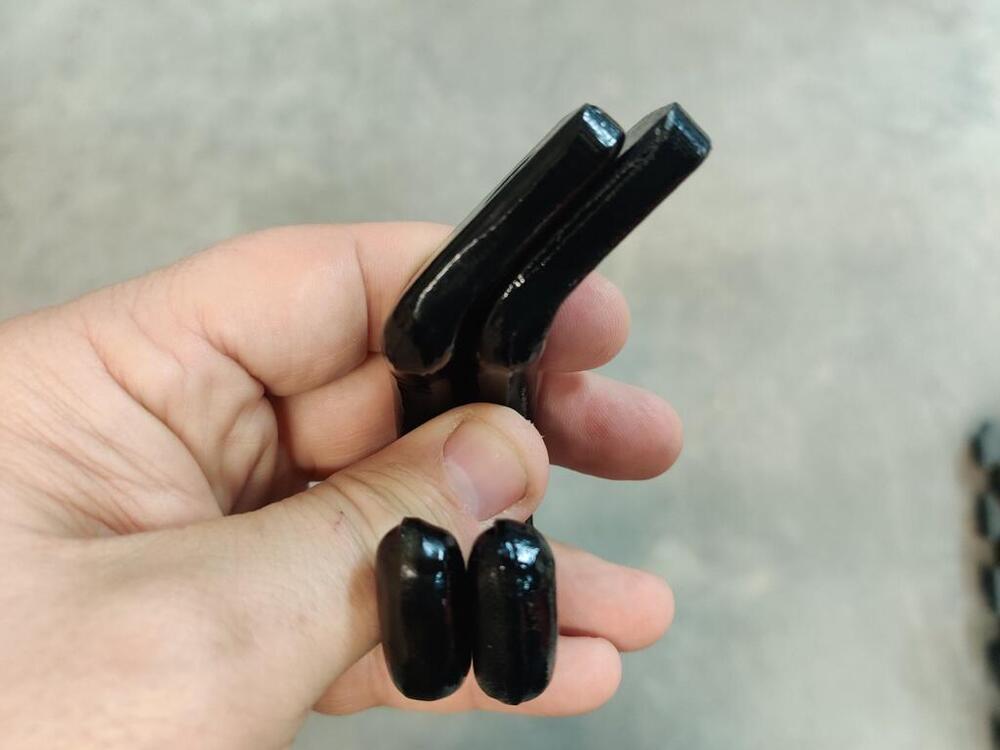
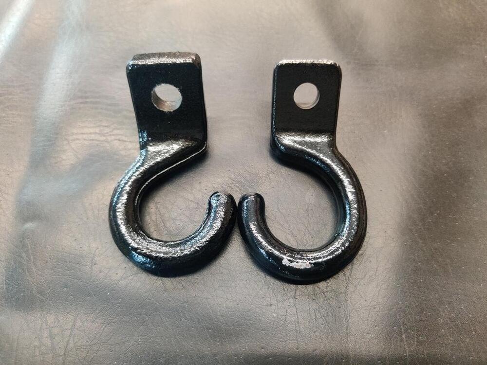
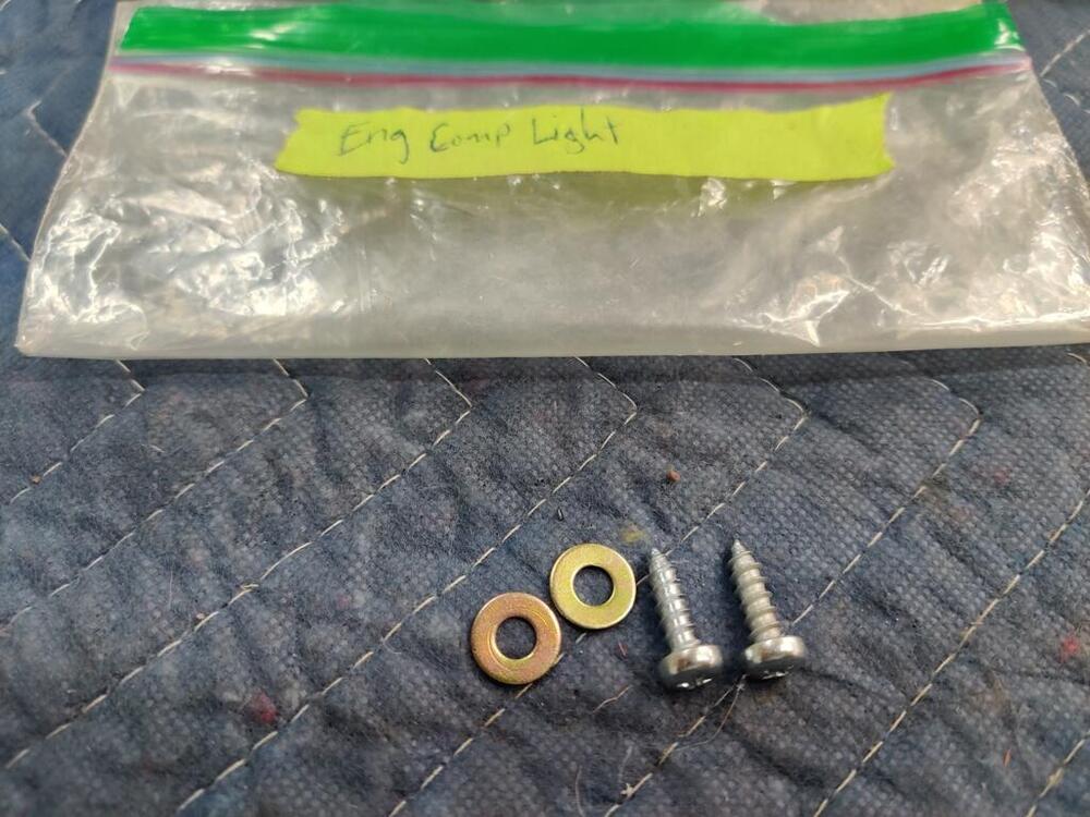
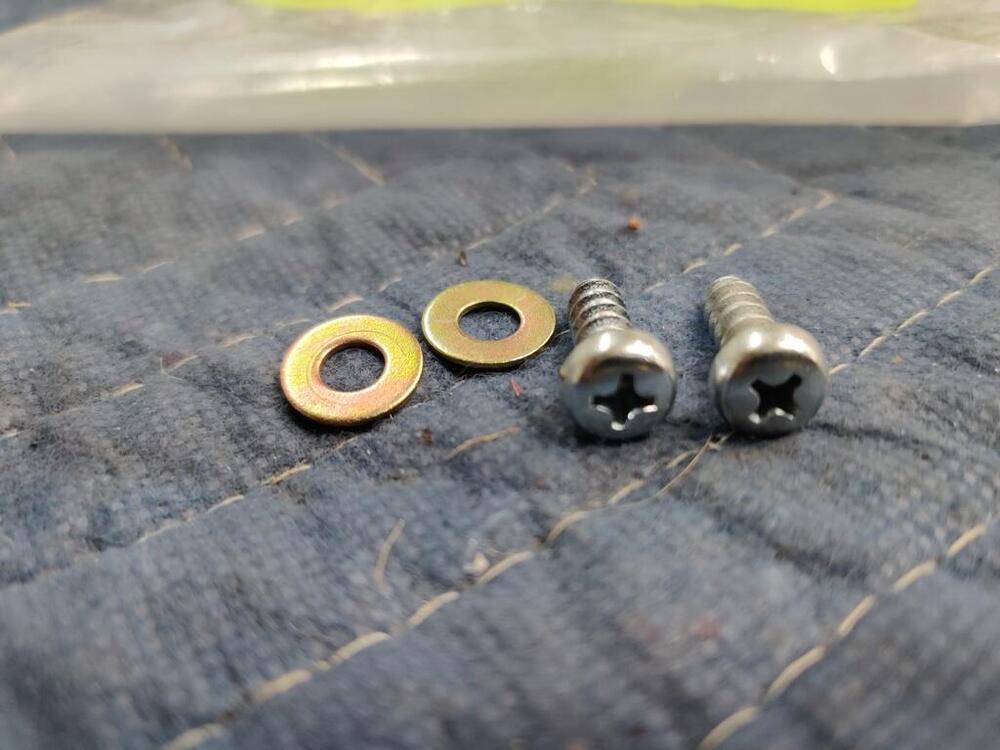
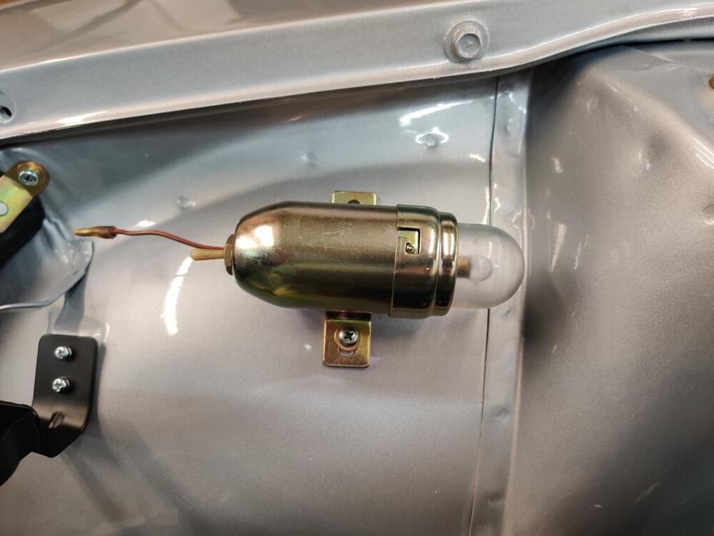
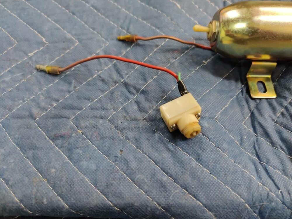
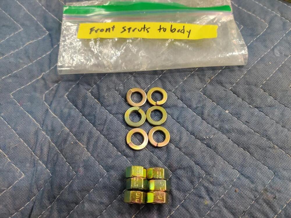
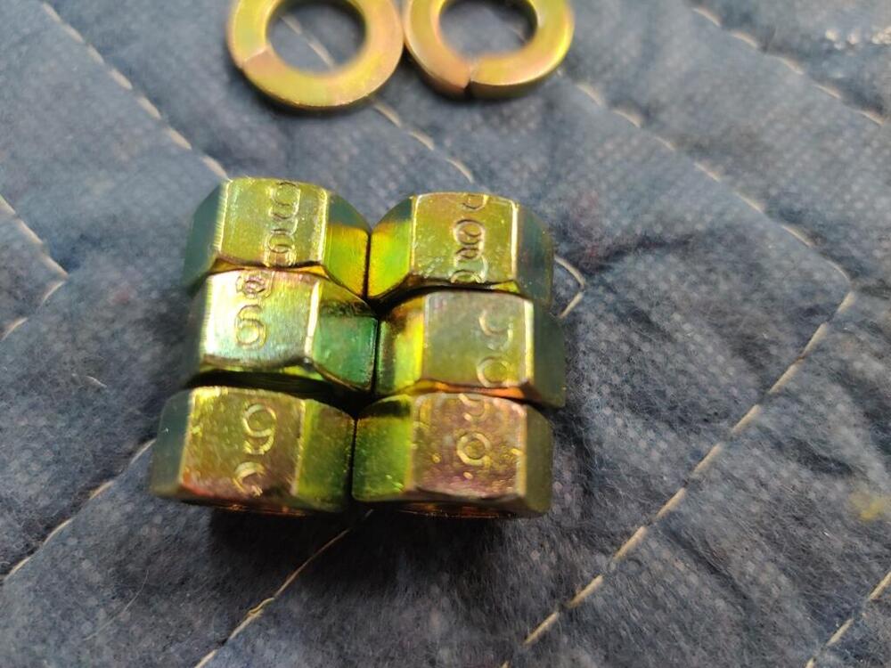
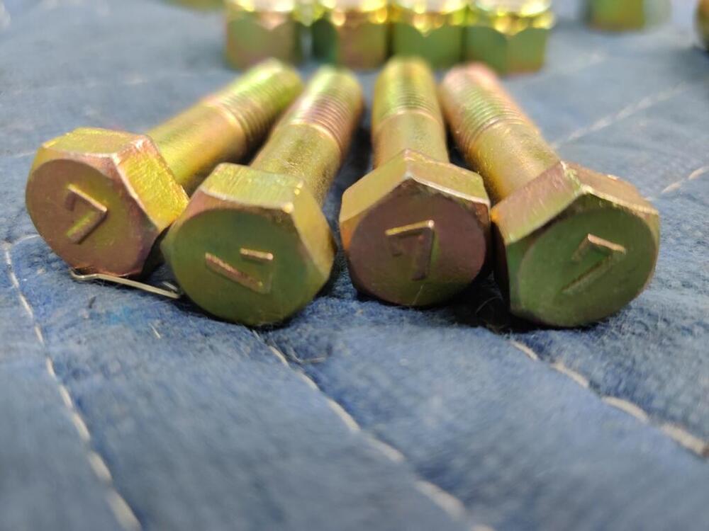
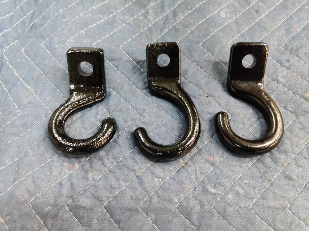
The hook on the right in the first pic was the malformed one. Now, it has been squished back into its original shape. Paint chips (of course) resulted from the work done to it in the vise and the hydraulic press. These particular hooks were used on both the front right and back right of the car. The left rear hook (on the left) is not quite symmetrical. Notably, the angle of protrusion from the body is greater. Looking at pictures of other 240z's rear hooks, I believe this is correct, and could have been intentional because of the exhaust system. Note the hooks on the Franklin Mint 240z which appear, to my eye, to be at different angles like mine: I didn't take detailed pictures of the engine compartment light rebuild. However, for this original light, I had to remove the original wiring by undoing the solder connections, glass bead blasting, plating, etc. and I had to buy a toggle switch (off eBay) to replace the original, broken one. I also purchased a replacement lens and gasket from 240zrubberparts.com. Front struts - nuts have "9" on them: I was missing one of the compression rod sleeves. Discontinued from Nissan, I found that Zcardepot.com had an OEM one for about 9 bucks. But having to wait for that stopped my suspension assembly progress for now.


-
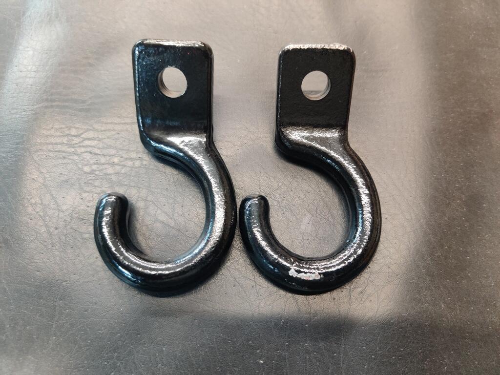
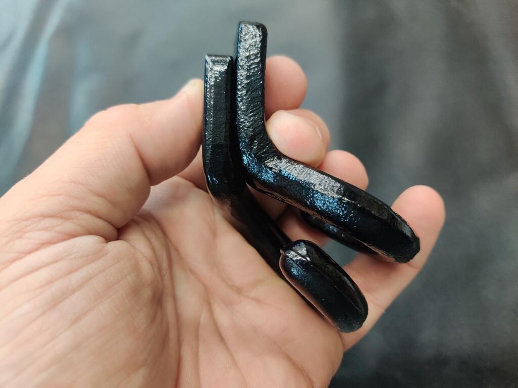
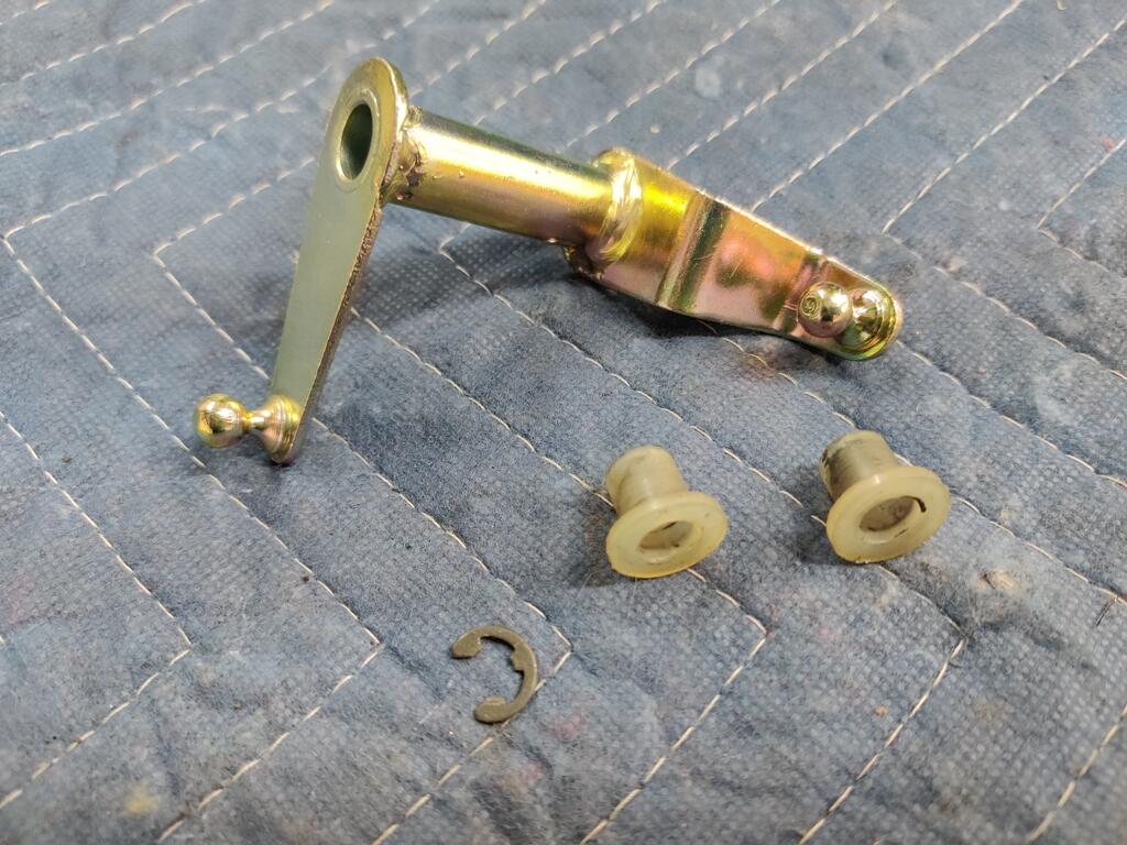
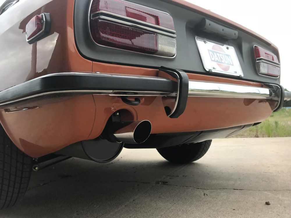
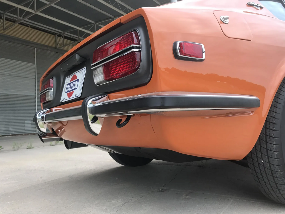
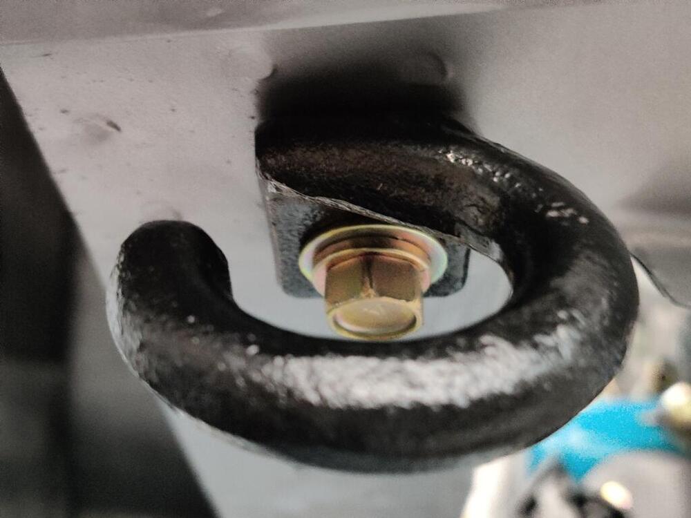
I think I figured out what was up with the tie down hooks. Speaking of which, don't you find it odd that these cars had these? I mean, it strikes me as a very unusual part to be on the car. Did other cars (foreign or domestic) of the same vintage have these? The one on the left of this picture, I put on the front of the car. It is actually for the left rear. Note that the middle one appears to be larger than the other two, with the hook part being more "open". Well, that it because it has been forced open. Perhaps this occurred at some point in the car's time on the road - someone pulled the car out of a situation... using this hook, and that bent it. I squeezed it in my vise to close the hook opening, and used my hydraulic press to correct the "bend angle". This worked very well to put it back the way it was originally. I'll add a pic later, but it looks just like the one on the right of this picture now. Either of these two can be used for the right rear, or the right front. I believe they are the same part. Left rear hook on the front right of the car. Hook portion should point the other way. I will need to replace this hook with either the middle of the right one above.

-
Interesting. I did not look at mine closely before installing them. I don't recall the bushings on the rack being asymmetrical. So, it didn't even occur to me that the clamps would be.
-
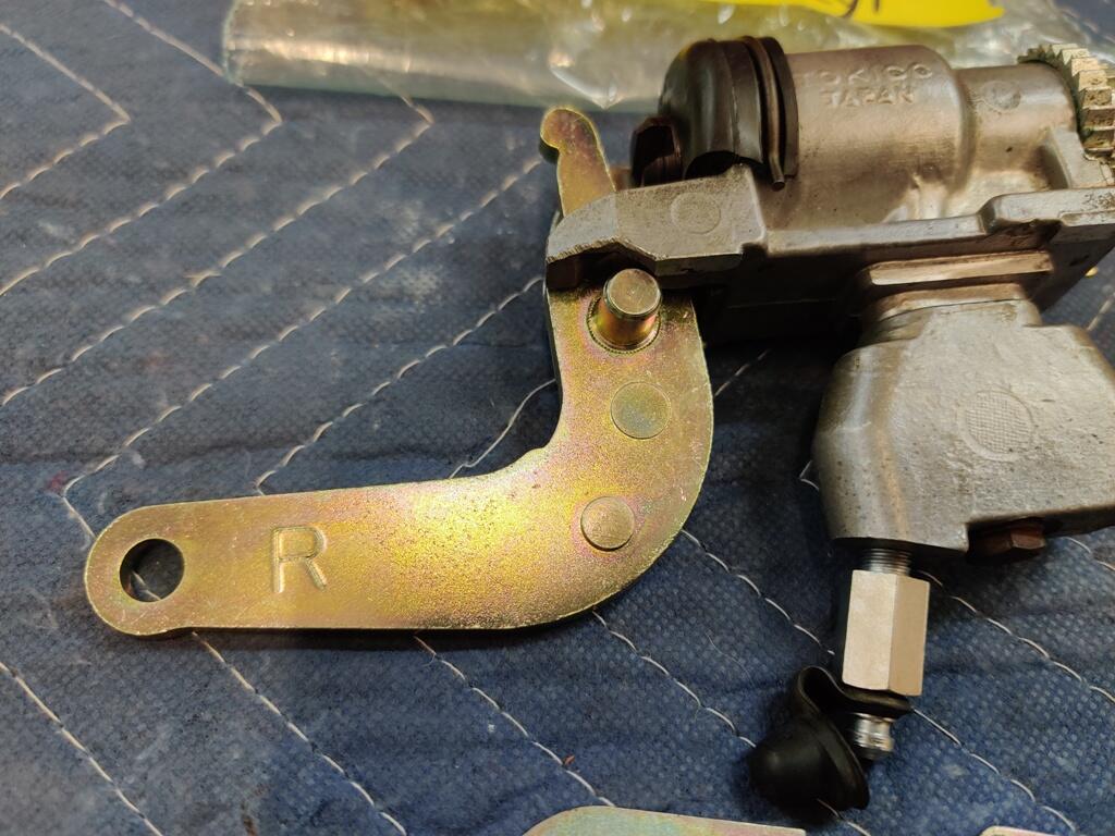
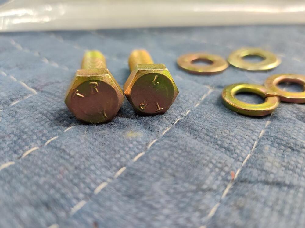
The ones I have appear to be NOS Tokico units. I was able to use the existing hard brake lines. Those levers can't be flipped and used on either side - they are side specific. I am stumped. I seem to recall seeing "L" on some of them before. It was only when I was taking pics before installation that I noticed, both of mine had an "R"s on them.
-
Ha ha ha!. I thought it would be something more... obvious, like Right. But both the left and the Right have the "R".
-
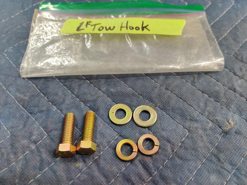
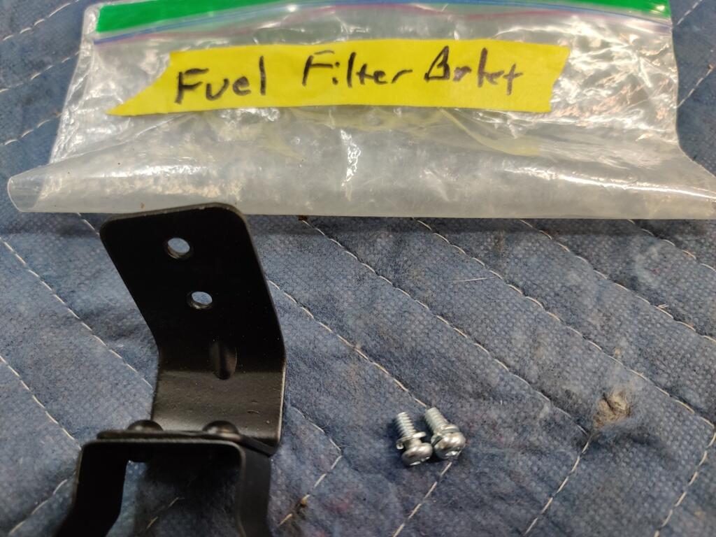
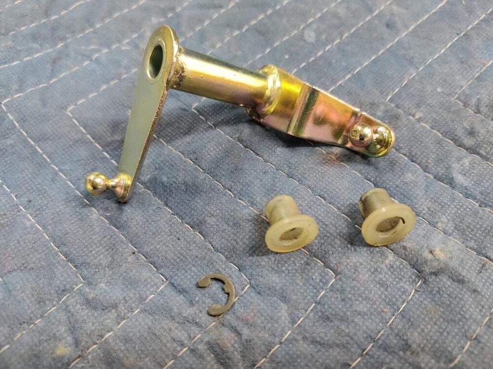
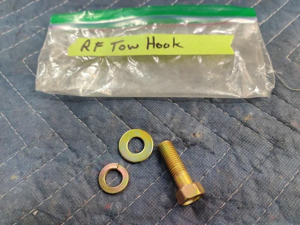
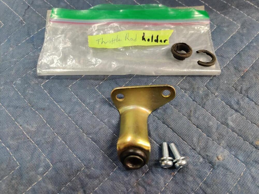
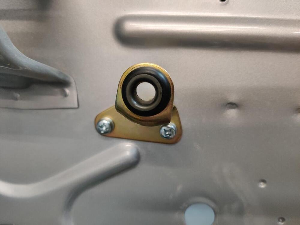
I put various parts on the car today. I am uncertain which of these tow hooks (third pic) is the right front. I think it is the one on the left out of the three: I was able to find a rubber grommet that resembled the original well. The fit with the plastic bushing was crazy tight. However, using some dishsoap made assembly possible.


-
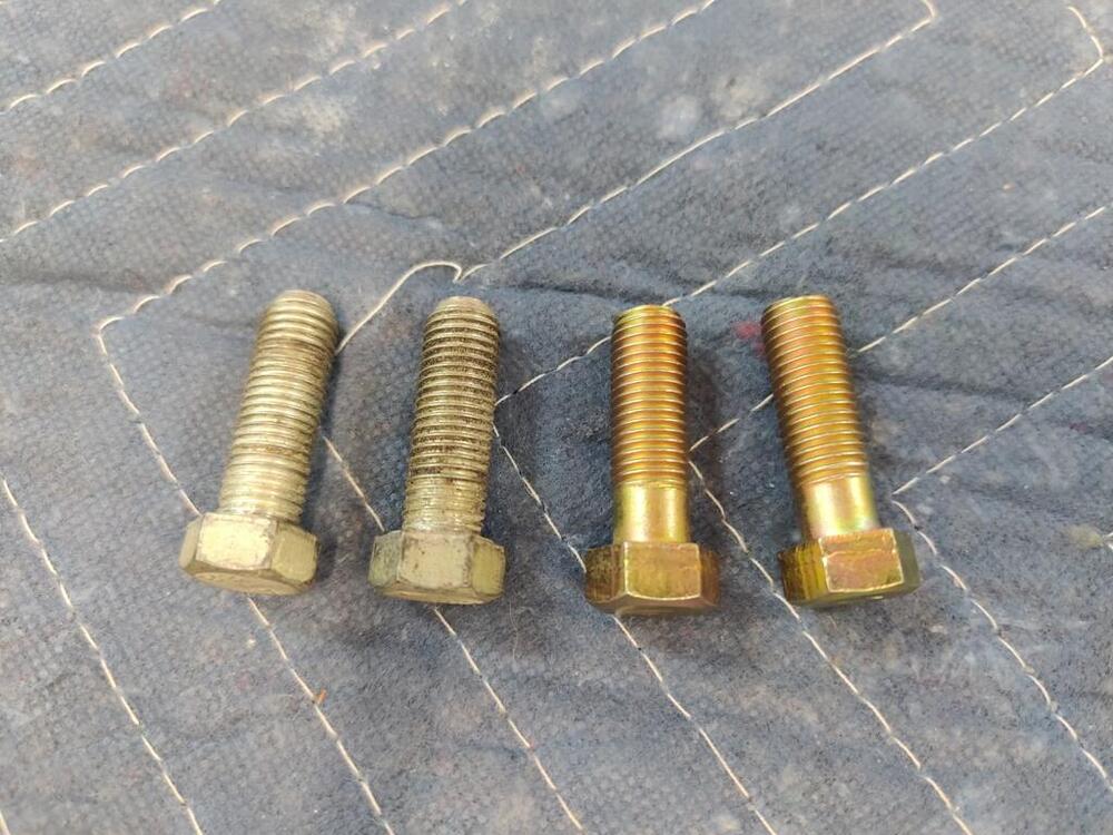
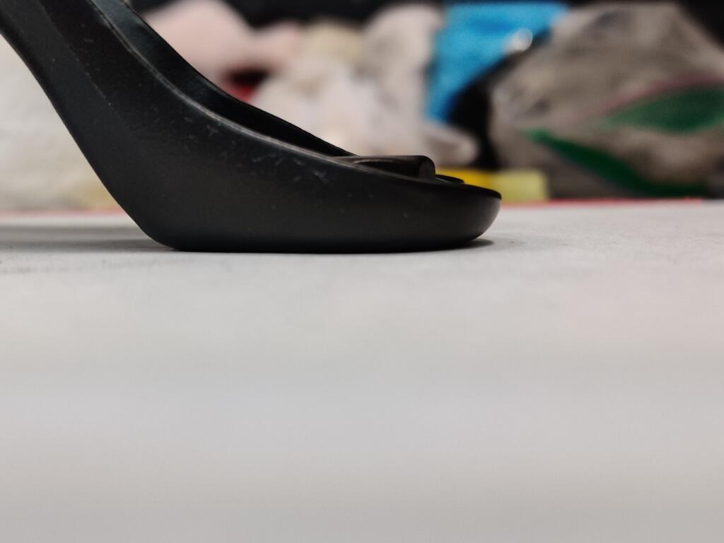
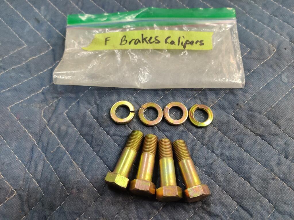
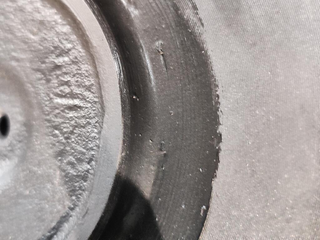
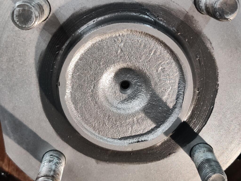
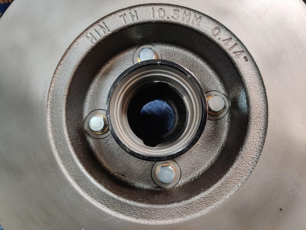
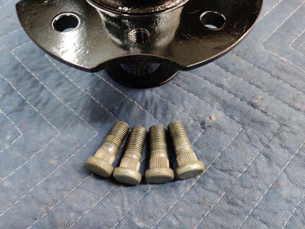
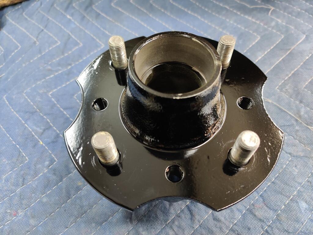
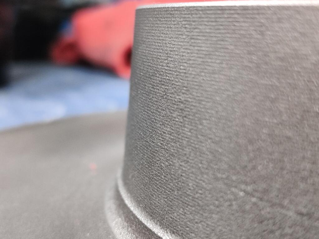
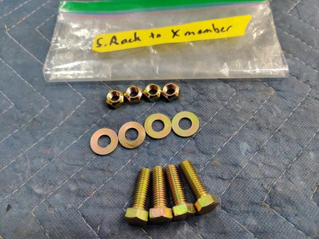
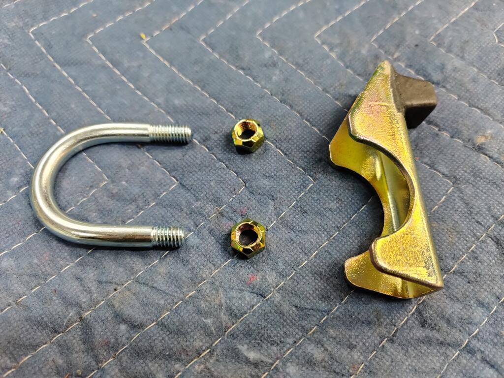
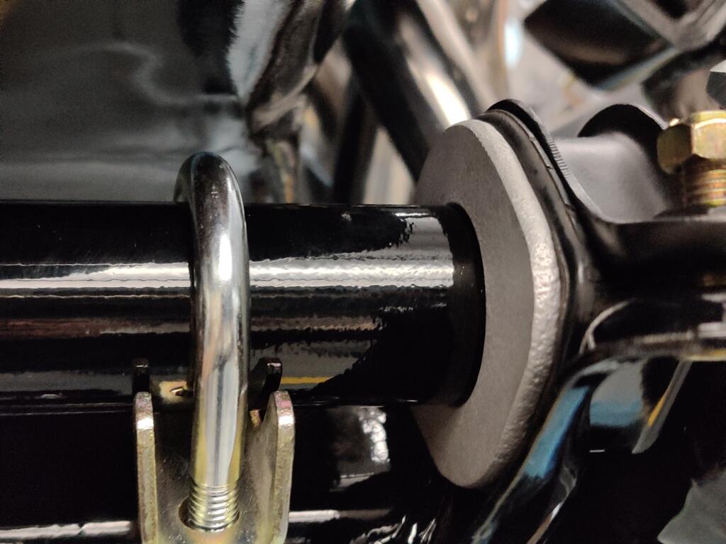
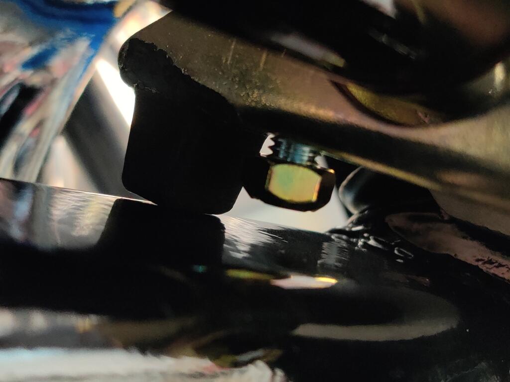
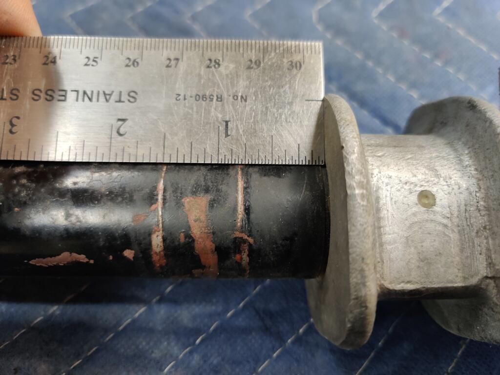
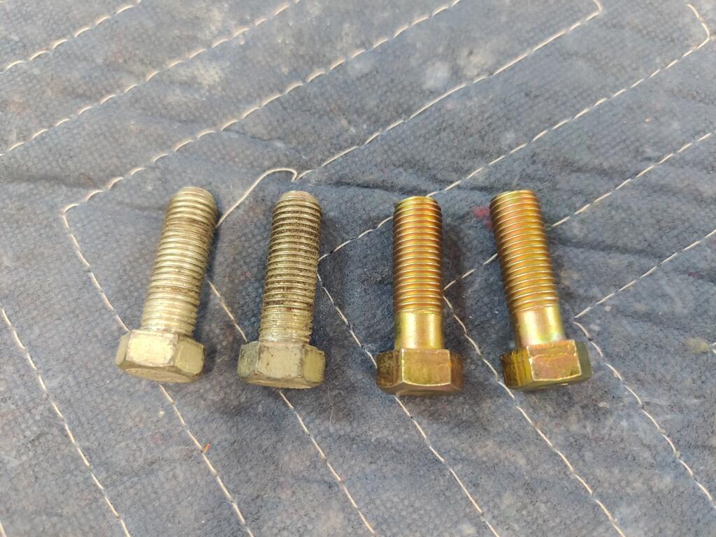
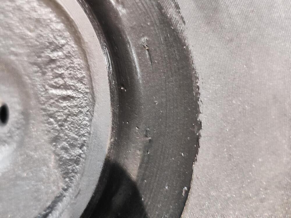
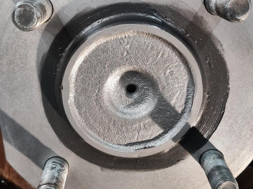
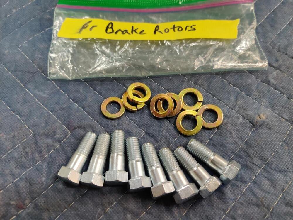
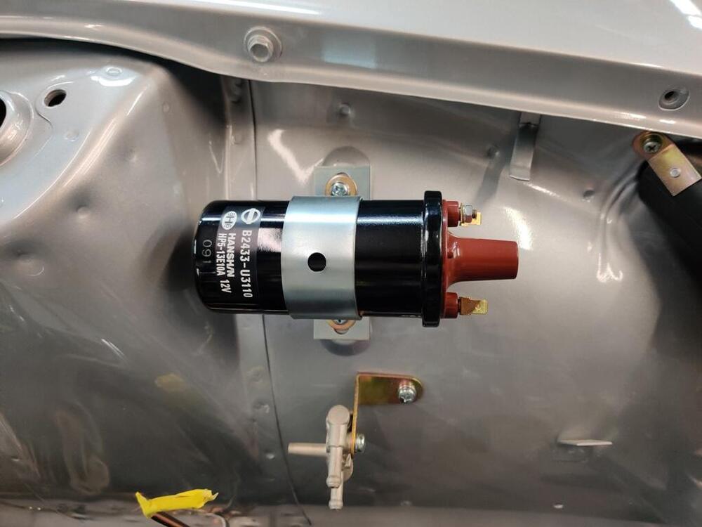
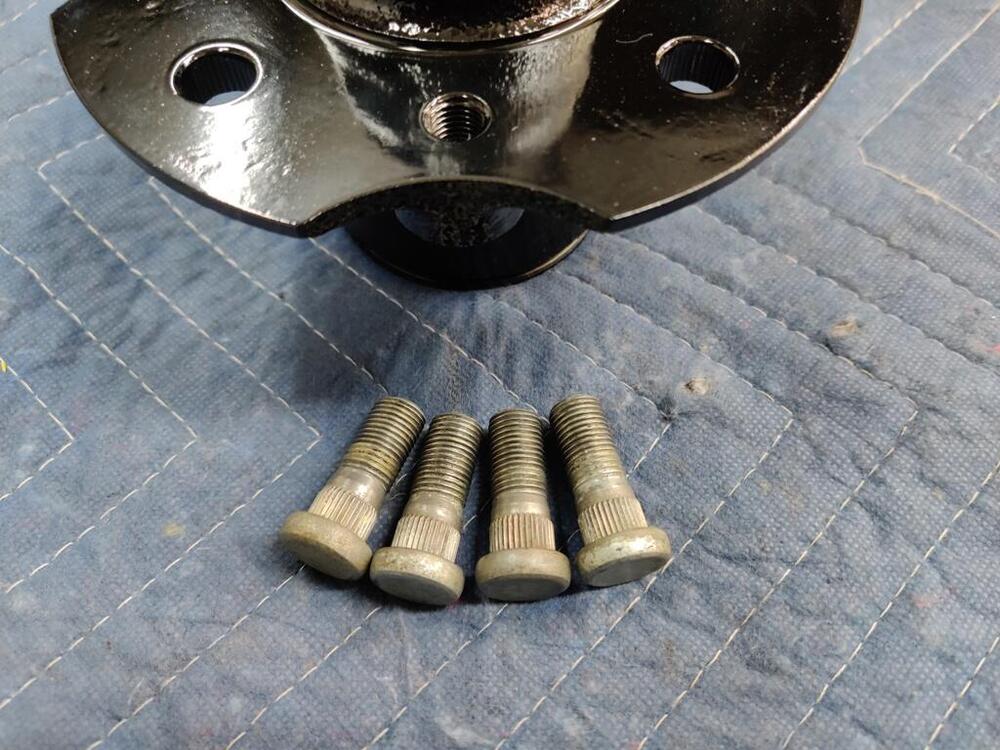
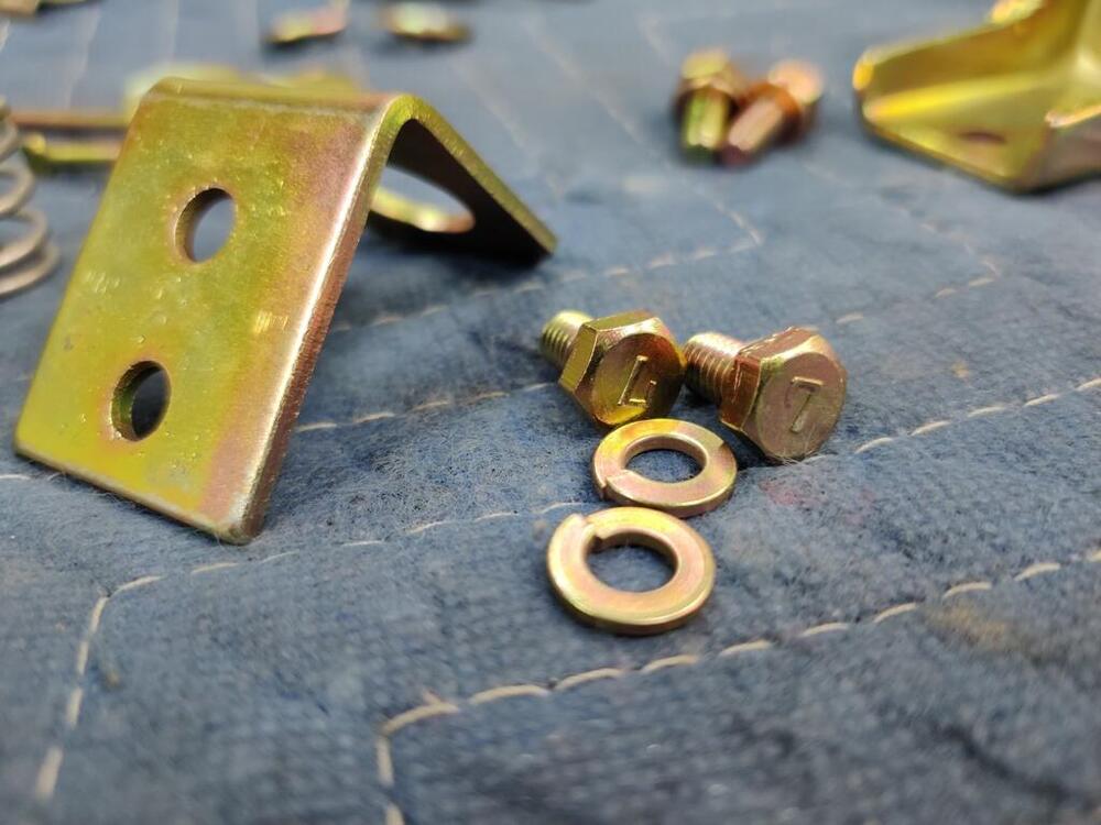
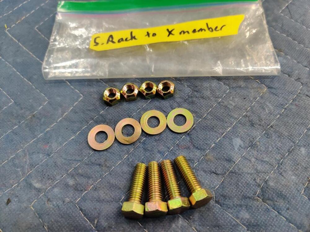
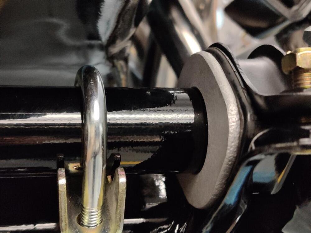
The 25 mm ones are challenging to use for the differential front mount cross member if installing new control arm bushings. I couldn't get the bushings to compress enough by pushing the arm into them to get the 25 mm bolts to start threading properly. I'll be able to use the two 30's I've got to get it started. Once it is close enough, I will use two of the 25 mm for the other two holes. I'll probably swap out the longer ones after the cross member is in place and move those two to the transmission crossmember. Then, it looks like I will have the right fasteners in the right locations. Working on the putting things on the car yesterday was very pleasurable. Not a lot of effort required, and was able to take my time and install parts that needed nothing other than taking them out of boxes and bags. I cleaned and installed front wheel studs into the hubs. I believe the front face of the hub came from the factory with a machined surface. I elected not to remove the paint on that surface. If I had a lathe, I may have dress it and clear coated. Oh well. The brake discs that came with the car are interesting. I note that the hat part is tapered - in the picture I have the camera resting on the disc surface. You can see the side of the hat has an angle to it. The quality seems higher than many I have seen. I believe these may be OEM, but there are no markings which confirm. I glass bead blasted the minor surface rust from the rotors and applied clear coat (spray can) to the front and back of the hat areas. I worked a little more on the rear brakes, installing the left wheel cylinder (anyone know why both left and right hand brake levers have a big "R" on them?), hand brake brackets, and the small sections of rear brake hard lines. I also tossed one of the drums on and a wheel, just to have a look see. Still waiting on brake shoes to arrive. I am also still waiting on the gland nut from Motorsport Auto. That is holding me up from putting together the front suspension. Next, I moved to the steering rack installation: For whatever reason, the steering rack clamp brackets were semi-gloss instead of gloss. Original finish pics - anyone know the correct orientation of the paint dots? Front/back, left or right? Steering rack brace. If you look closely at the U bolt, you will see that one side has more threads than the other. That longer side goes towards the front of the car. The brace is not clamped down yet in this third pic. Don't think it matters, but used an old rack to determine the location of this brace. Today, I will be adding items to the engine compartment.


-
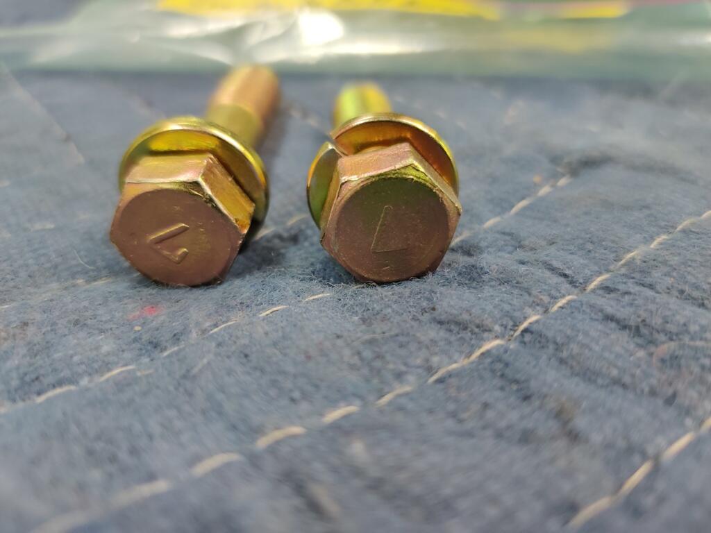
Oh, interesting! I believe I have many that have a 7 on the head and are only 25mm long. Thanks for the offer! I will take a look again at what I have on hand today, and let you know.
-
Interesting. My car is a 6/71. Thank you for those pics. Very helpful to me. Those are loop. And from 4/71 also. Wild. I have never seen that type of jute (reused carpet) on the back of original carpets. Perhaps a prior owner added that? Why are you thinking of re-dying and using them? Just, they aren't that bad? Or, is part of the reason the lack of availability of new carpets that look enough like the old ones? Other reasons?
-
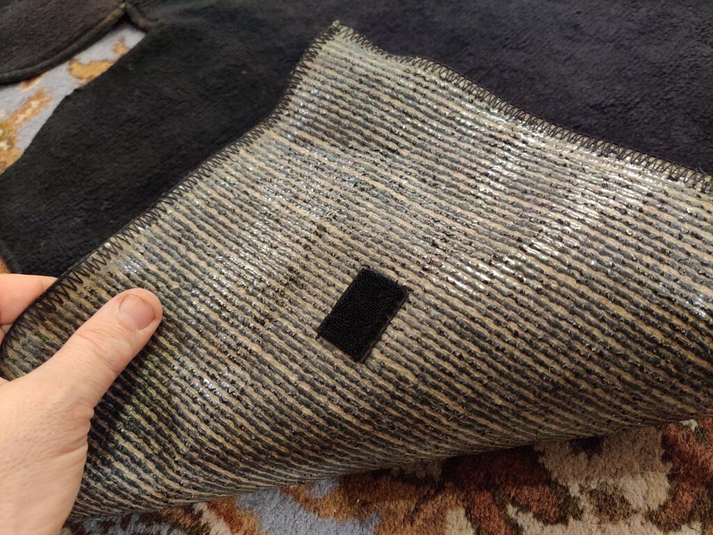
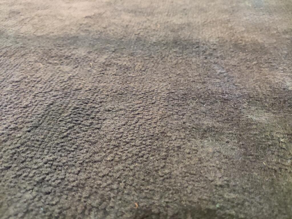
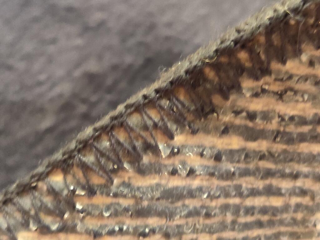
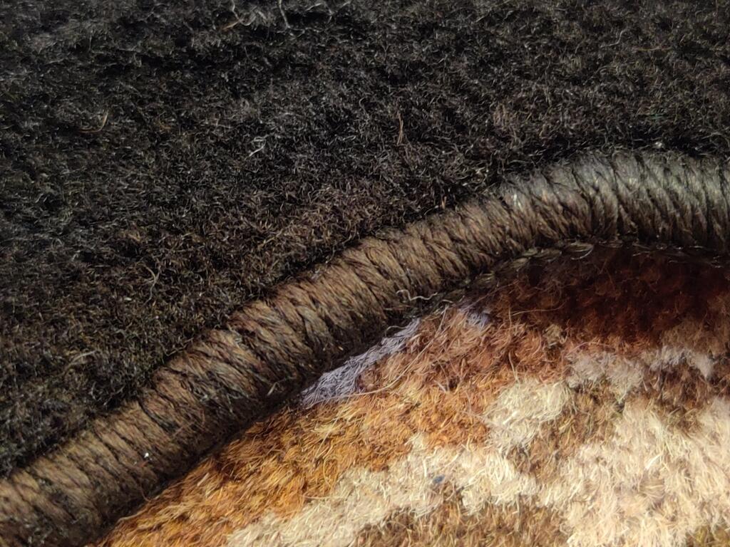
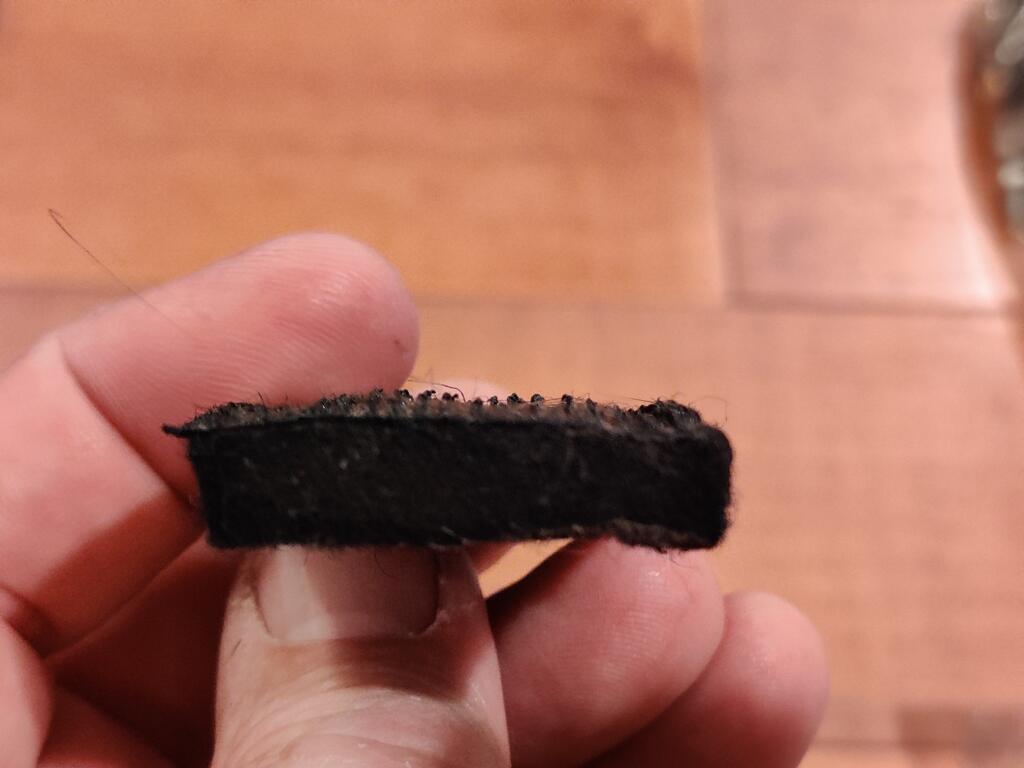
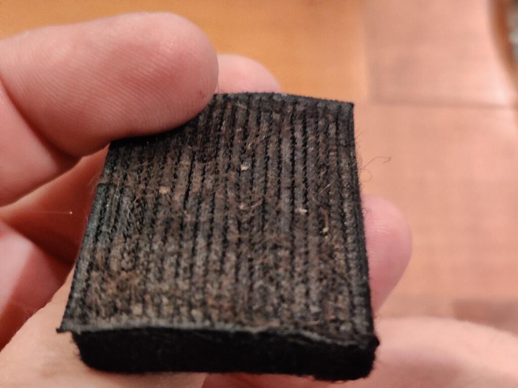
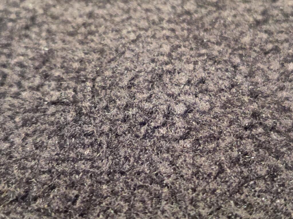
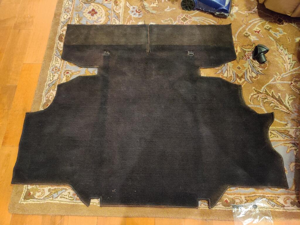
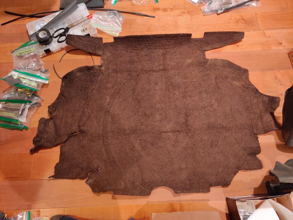
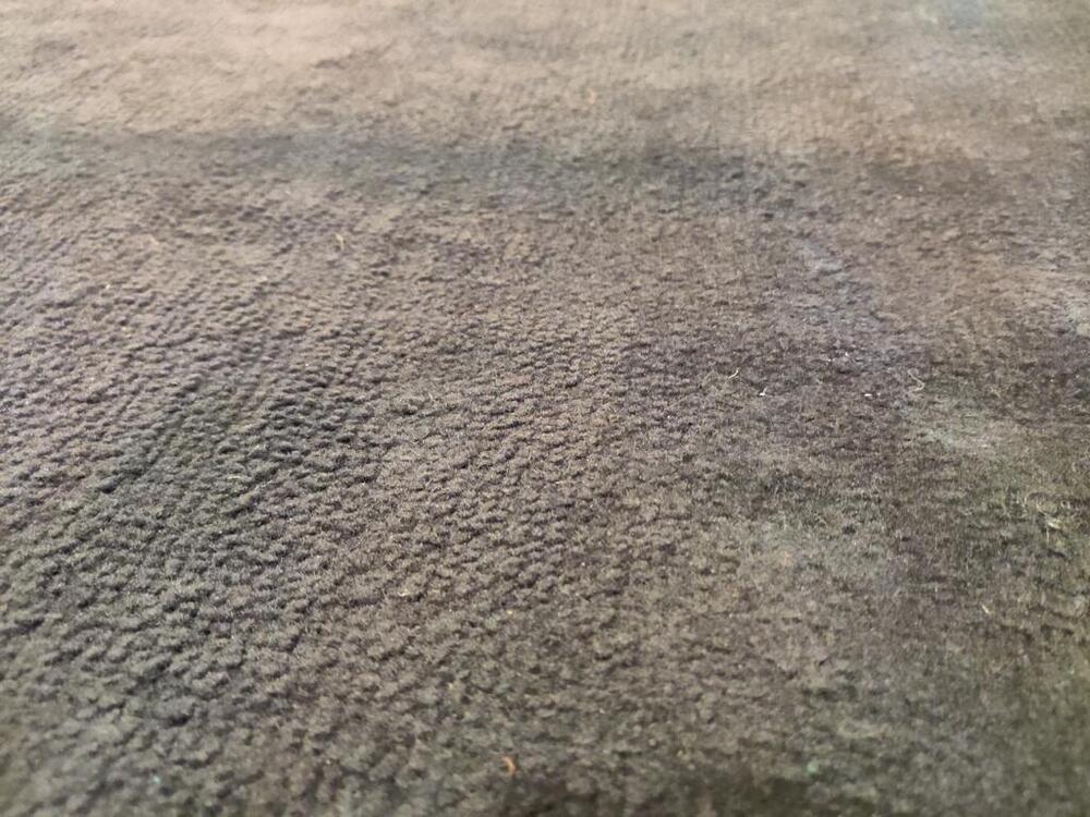
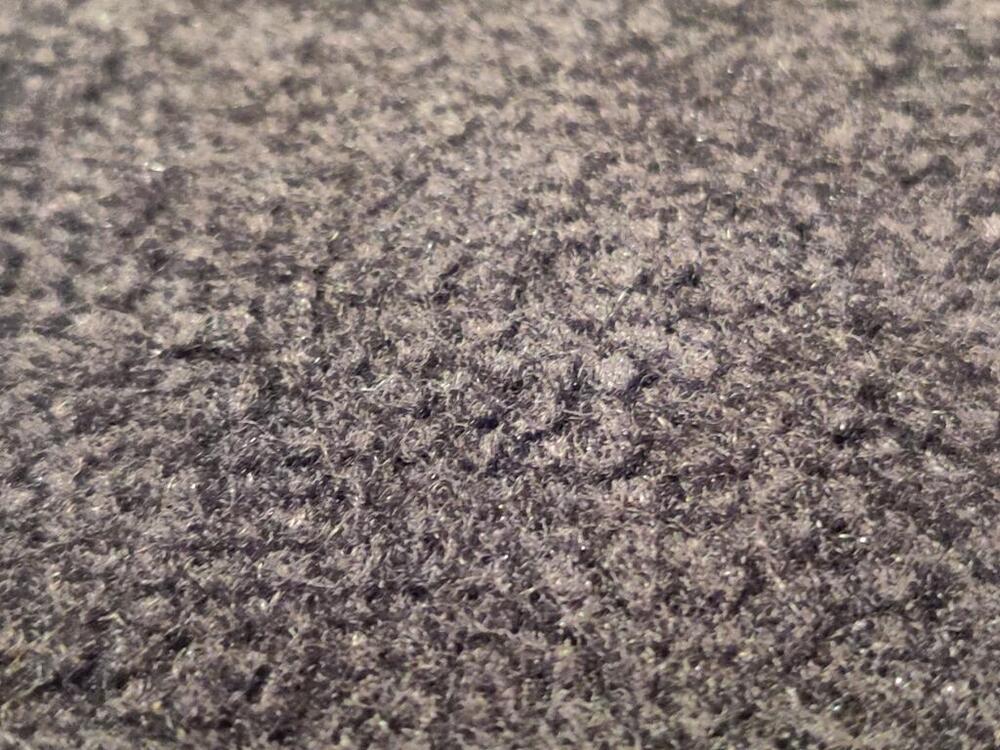
I found this carpet and matching jute on eBay. It looked original to me, and I was interested in getting it for the purpose of using it as a pattern for having some custom carpet made because my opinion is that the kits that are available these days are rather lackluster. When I spread it out and took a close look at it, I was surprised. I was expecting it to be loop carpet. However, it seems like it is more of a pile carpet type. To my understanding, one of the most "authentic" carpet kits currently available is this. But, that is loop carpet - it is very different. While from pictures, it may be hard to tell, this carpet definitely isn't compose of upside down "U"s. It is more like each twisted strand of carpet has had it's top lopped off: Since receiving it, I searched for information about original carpeting and come across various posts on this forum. It seems, that original carpets included both a "pile loop" as well as "loop" versions, though it is not entirely clear to me which year cars got which. From the information I found, I believe this carpet to be original. I am mainly basing this on the color of the backing (underside) and the age, as apparent from the fading. It is actually in pretty good condition compared to many I have seen in pictures. I have seen several with more color fading, and several with more wear. Additionally, it came with one "block" of dense material. This piece is normally glued to the hatch floor. It is about the same thickness as the jute... roughly 1 centimeter. A few days ago, I became aware that Chester and Herod is still in business. I thought they were out of business. This was another reason I was thinking about having custom carpet made. However, now that I have been looking through various carpet related posts, I have some new concerns. From the most recent pictures and comments I have seen, I am wondering if the Chester and Herod kit's fit has degraded over the years, and if the loop or pile options they have are very different than this original carpet. Does anyone have any info to address my concerns? I'll likely attempt to get some current samples from C and H to evaluate how similar or different it is, but I looking for additional opinions/info from anyone with recent C and H 240z carpet purchases.


-
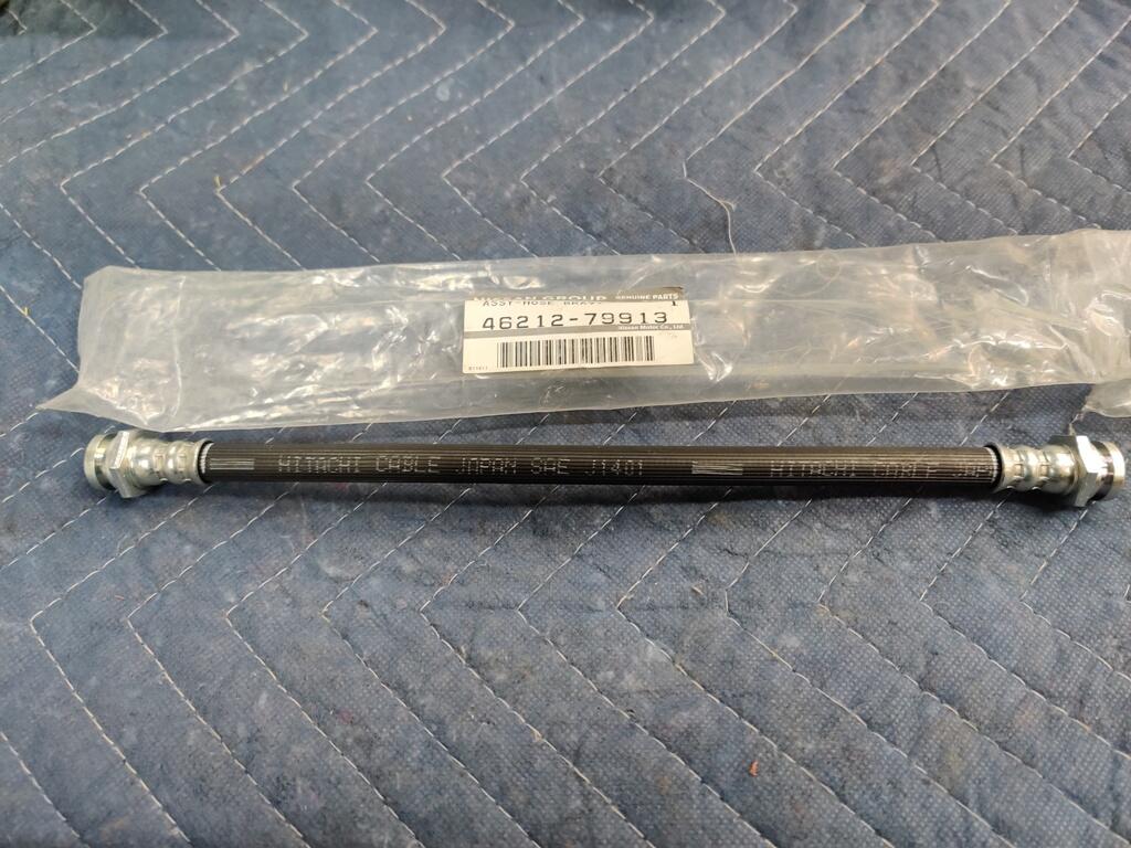
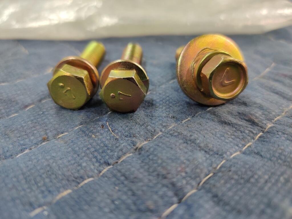
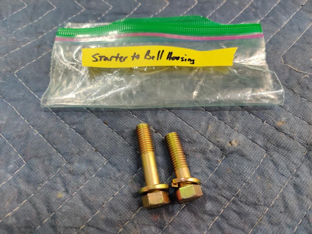
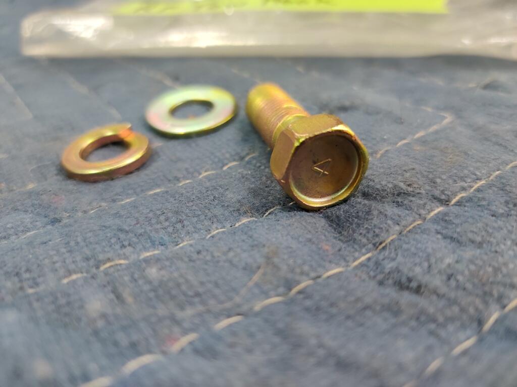
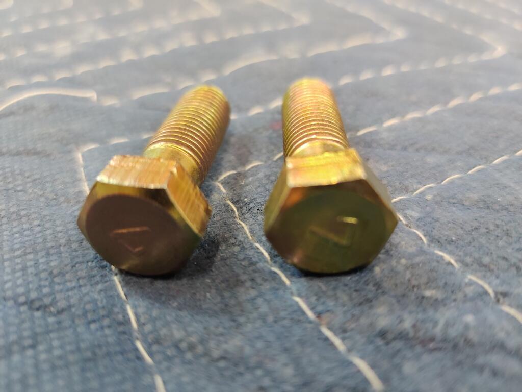
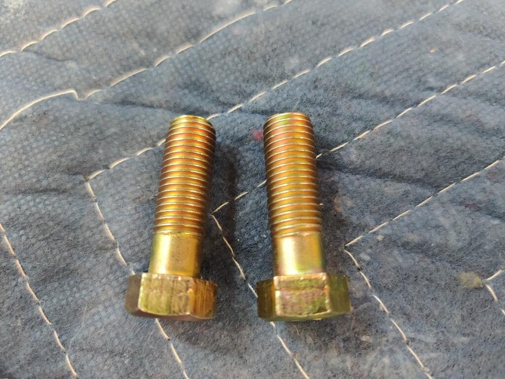
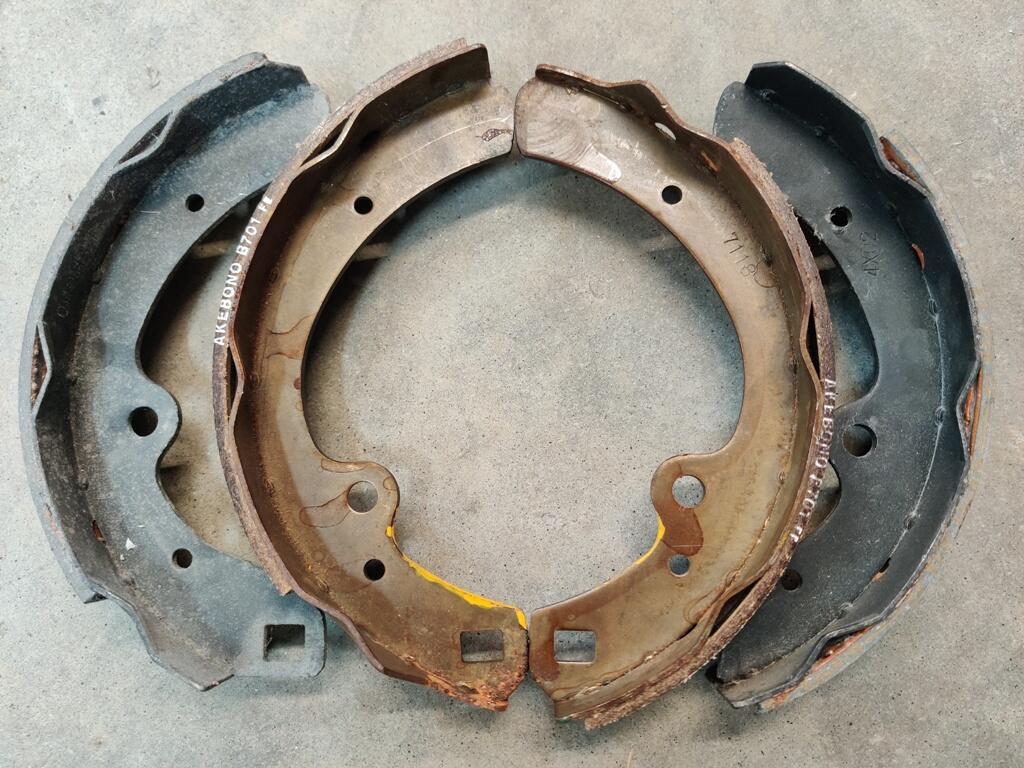
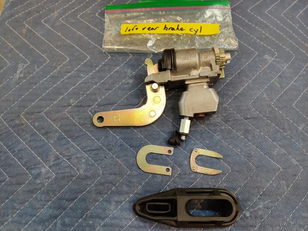
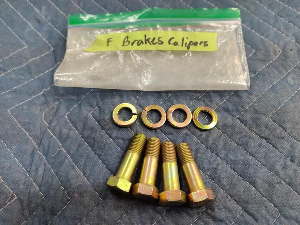
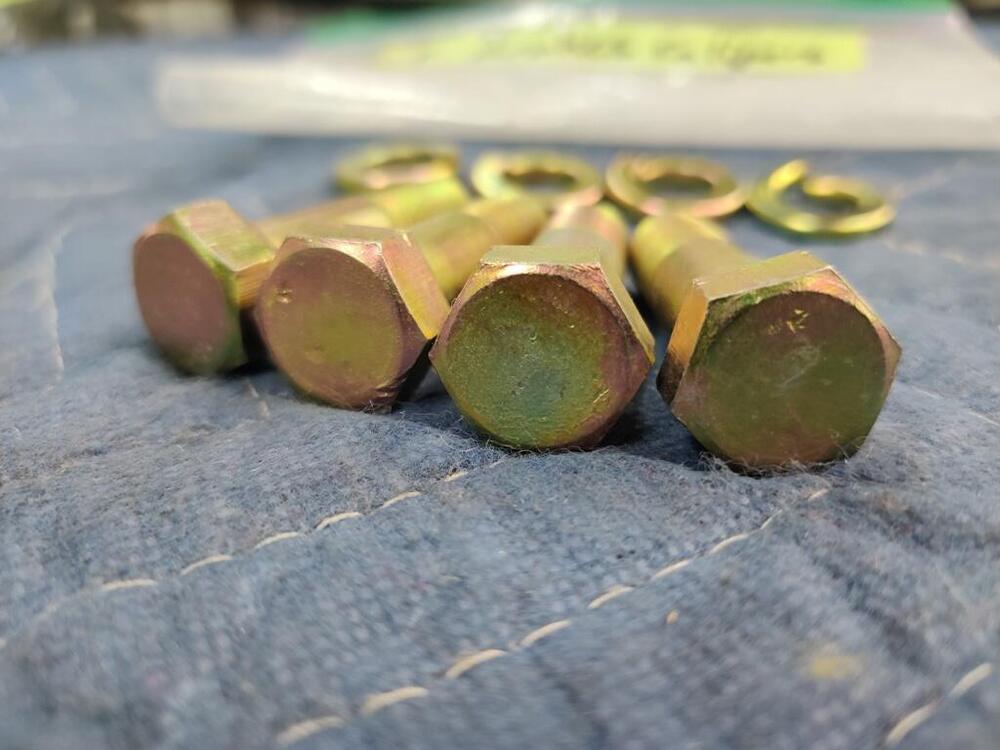
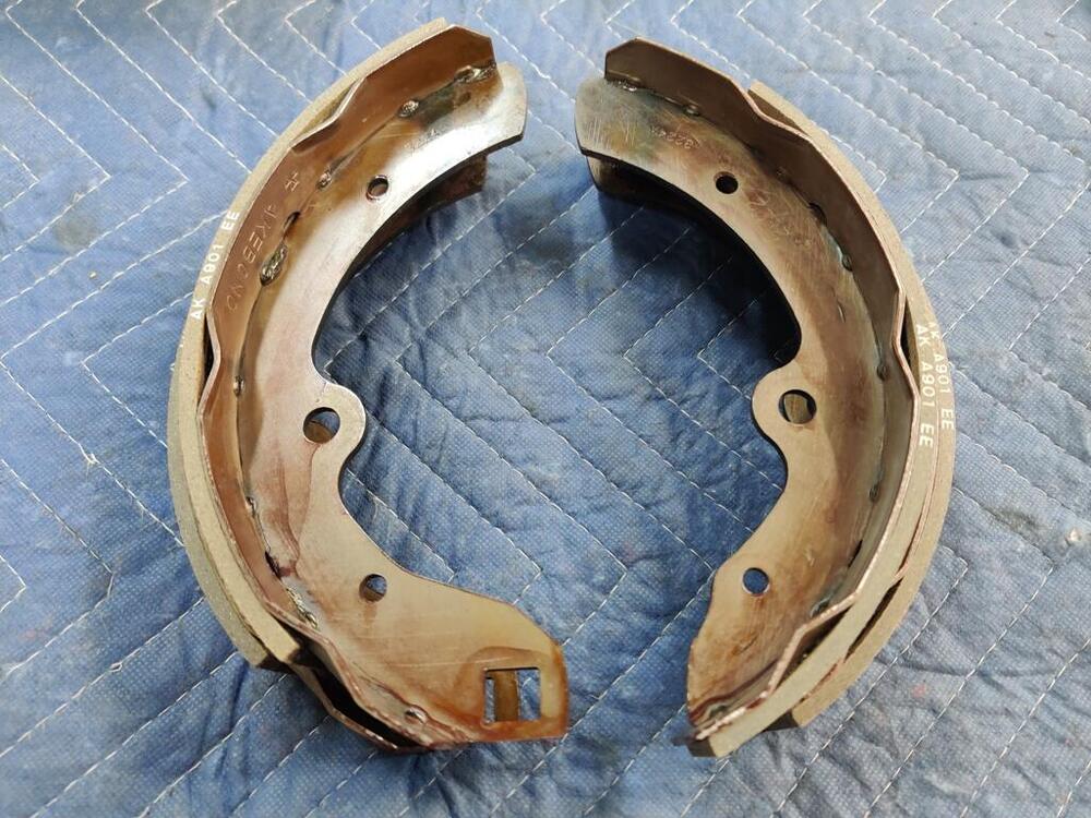
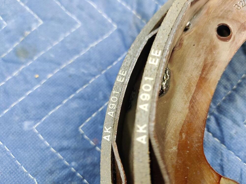
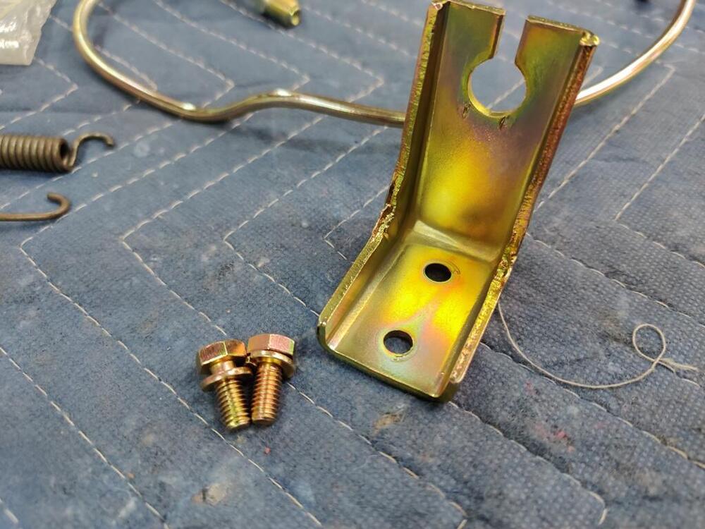
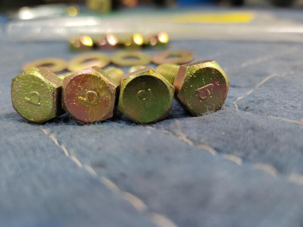
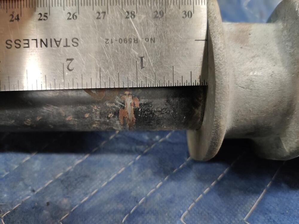
I found two of them - I think. They are 30 mm long, but the threaded portion is more like 23 mm instead of 21, by my measurement. The prior owner of the car had done some rear suspension work and apparently, while going through that work, was replacing most of the factory hardware with 8.8 grade stuff. Luckily nearly all the stock hardware was kept with the car. But, two of the bolts I do not have. And interestingly, my transmission crossmember bolts are similar, but have 9's on them. So they aren't right either, I guess. For now, I'll use two of the grade 8.8 bolts (pictured). While I'd like to get 4 of these (two for the crossmember and two for the transmission), it isn't the end of the world if I can't track some down. I also ran into this unexpected problem tonight - the "240z" OEM brake shoes I bought are for some other Nissan model. Note the location of the "eyelet" holes in the metal stamping for the two inner (OEM) vs the two outer (black) shoes (aftermarket) that were installed in the car when I got it. Whatever B701 FE is, it isn't unique to the correct OEM versions of the shoes for a 240z. Brake shoes are pretty cheap parts for this car, comparatively. I'd like to have some OEM ones. So, I found some online in Austria. I'll see if those are legit. Otherwise, I guess I will install the ones that were installed by the previous owner. A few pics of the brake cylinder I also installed tonight: