inline6
 Subscriber
-
Joined
-
Last visited
Everything posted by inline6
-
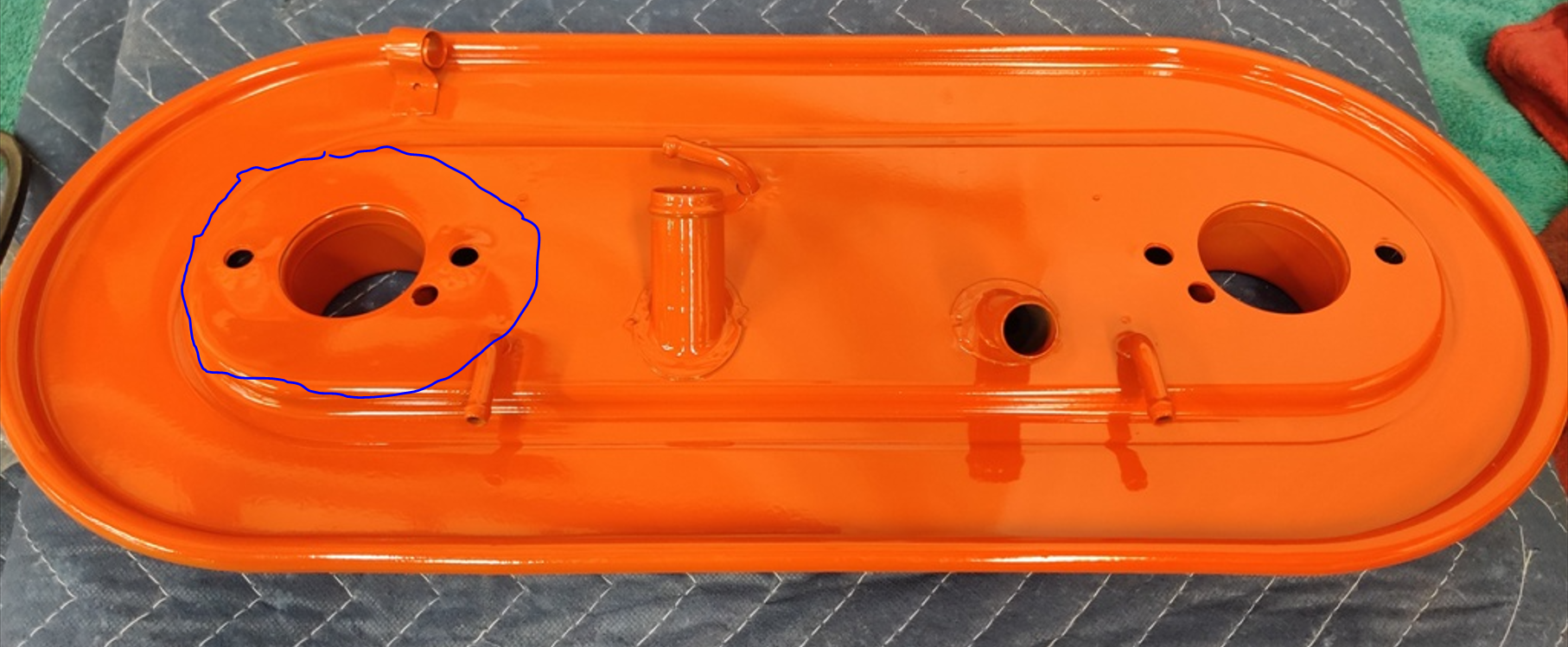
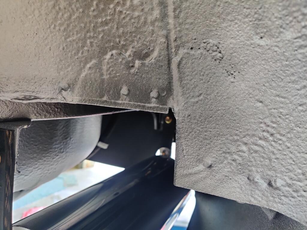
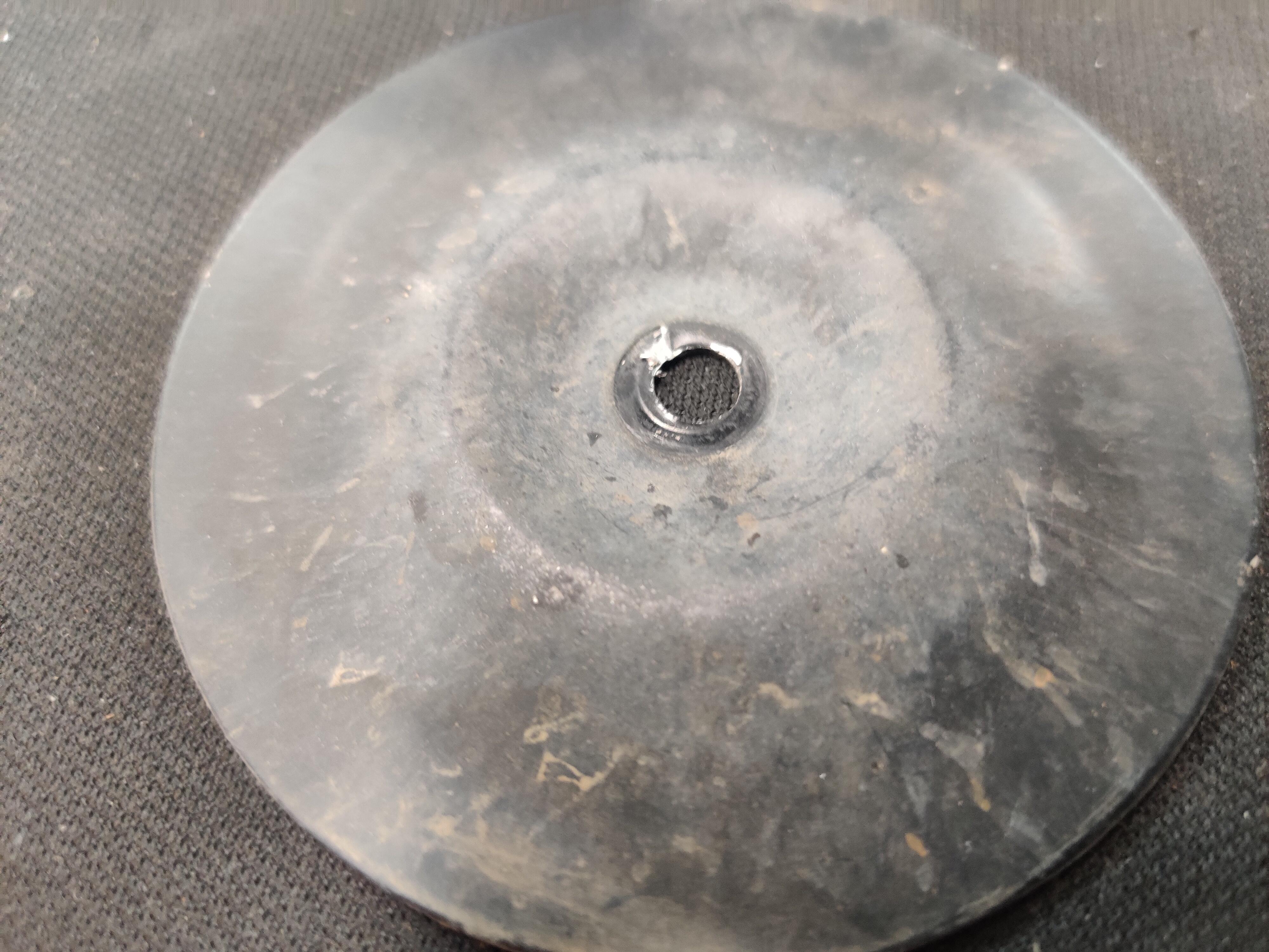
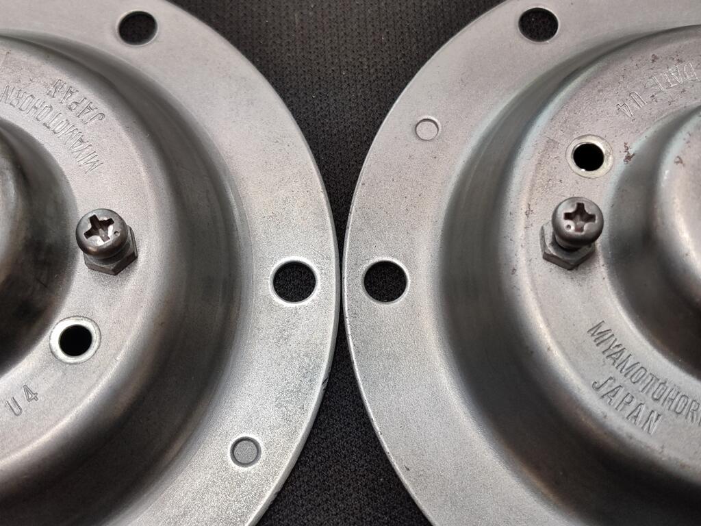
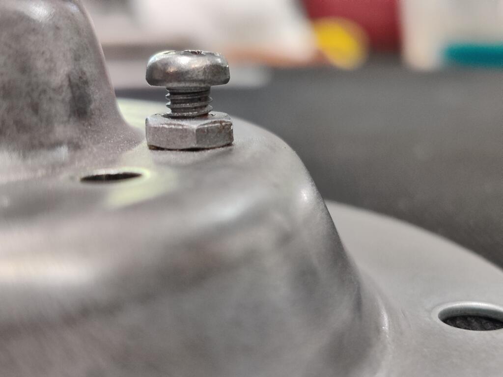
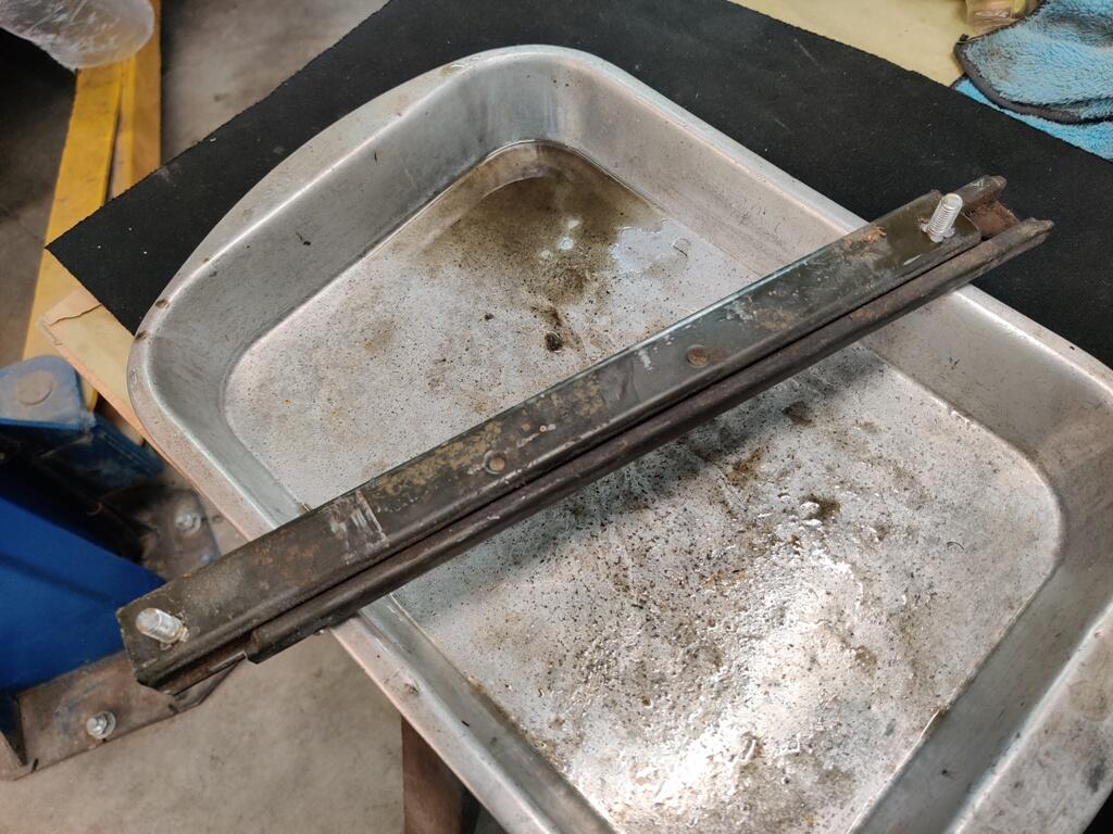
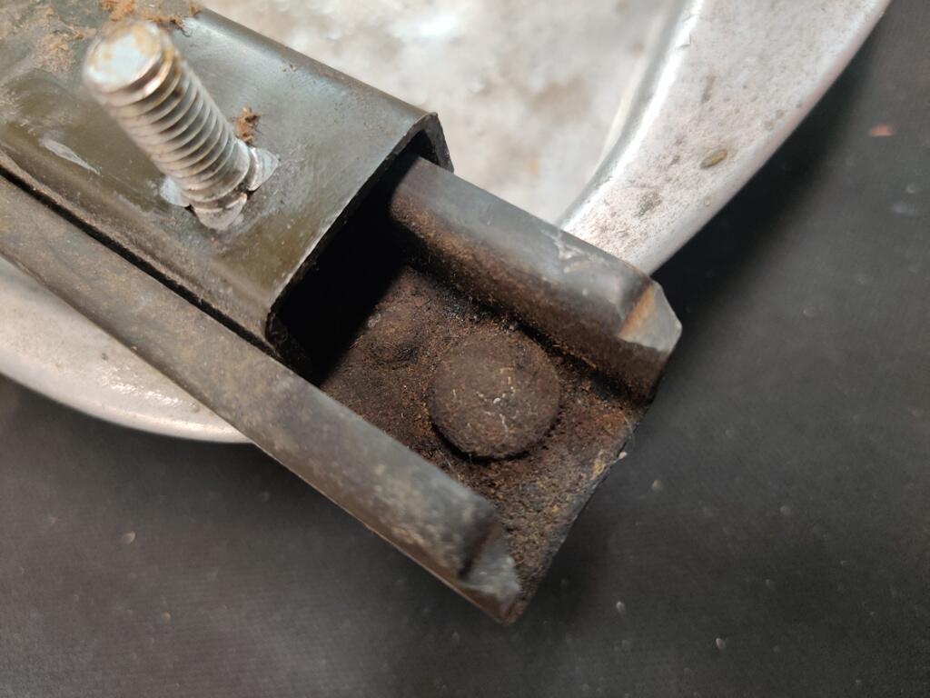
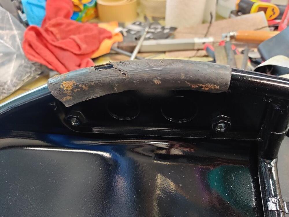
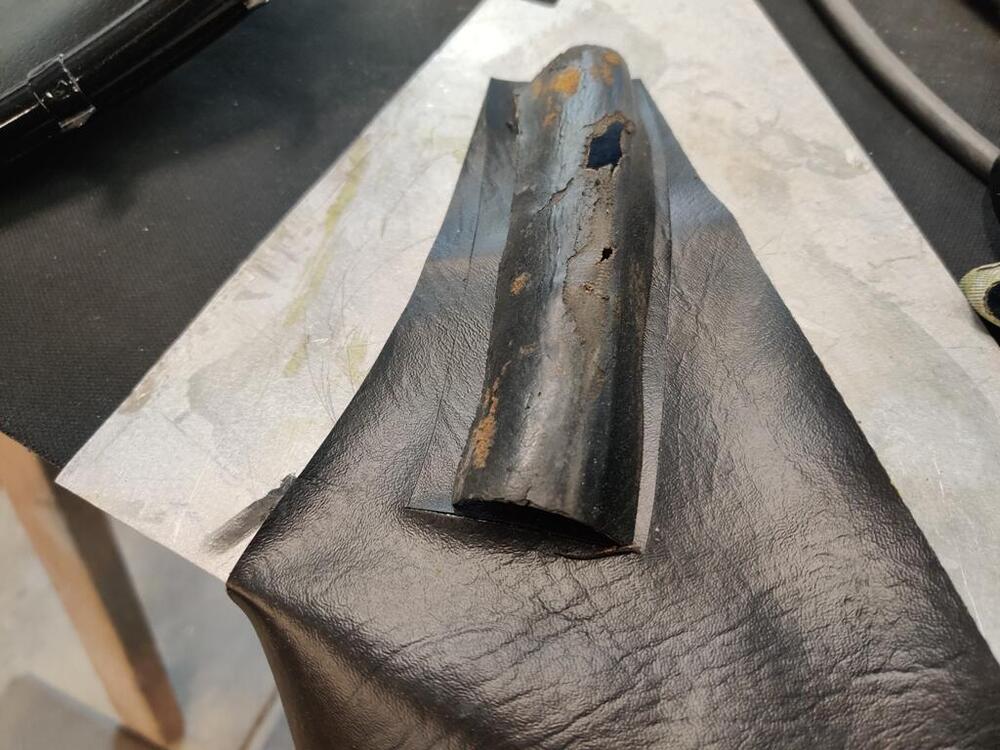
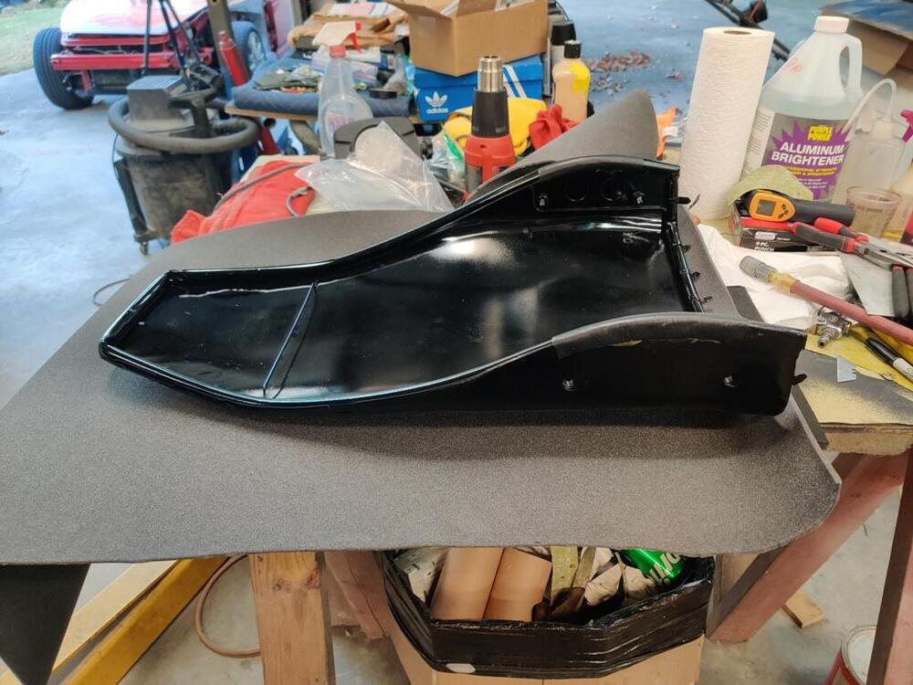
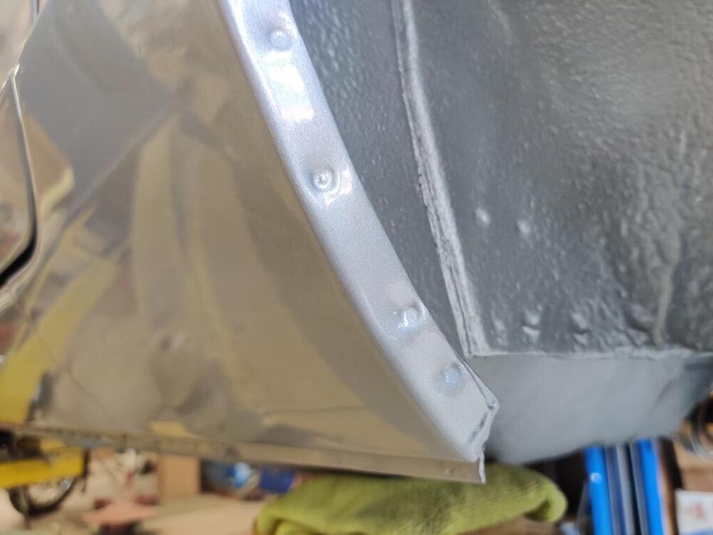
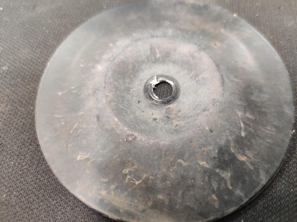
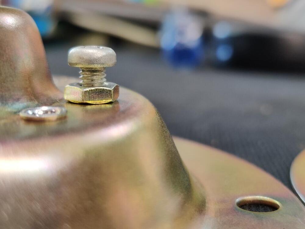
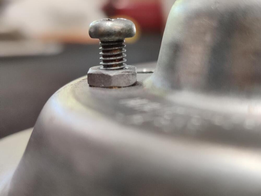
 The seals inside are original. They are made of a type of rubber that I don't think ever compressed much. I am beginning to think that my problem is the back plate. I suspect that somehow it the outer edge has been bent back... If you envision it mounted to the carburetors, then I think the outer portion of the plate has been bent towards the engine. I took my back plate off the engine last night and set it on a work bench. I examined everything very carefully. At the front of the filter housing, the gap (to the cover) is a bit larger than at the rear. Though it is hard to see, upon close examination, I see that this circled area of my filter back plate is pushed in a bit. With this surface pushed in, the outer part of the housing moves away from the housing cover. I found this picture of a back plate on eBay - note the "plane" of this surface: And here is mine: While I think this is part of the issue, I am not sure it is all of the issue. At the back carburetor location on my filter housing back plate, I don't see evidence that it is bent like the front. And the filter cover doesn't contact the seal there either. I'd say the distance at the back is about 1/8". While at the front, the gap is about 1/4". I am going to try getting creative with my hydraulic press to attempt to address this. I have in mind putting the front air horn down face first, and then using some plates or boards to bridge across the backside of the plate, and then use the hydraulic pressure to push on the plate on the curled edges. Effectively, the area where the horn is should move "up" (horn will be face down in the press) and the back plate will move "down". I will try to protect the paint with soft rags placed in suitable locations. If anyone can do some examination (to see if bent) and measuring of their back plate (if not bent), that would be helpful.
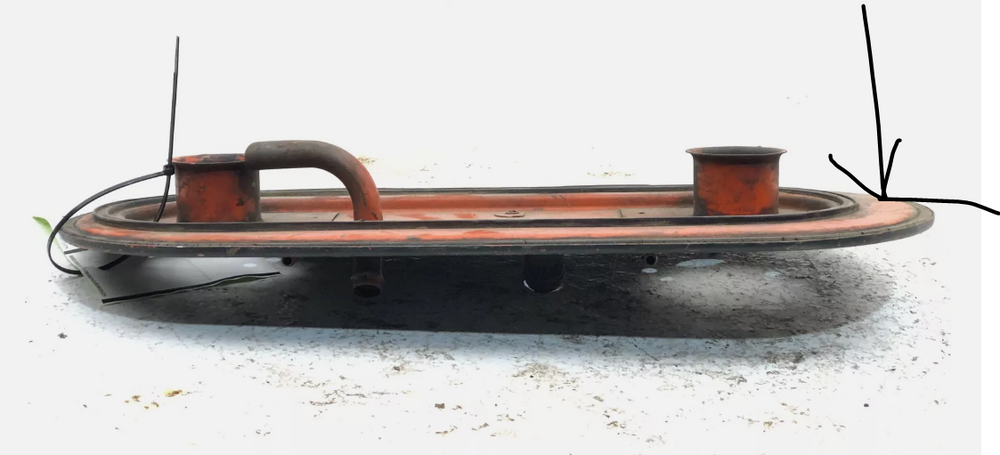

-
AAAAAAAAAAAAAHHHHHHHHHHHHHHHHHHH! Jeez! Sorry that happened Charles!
-
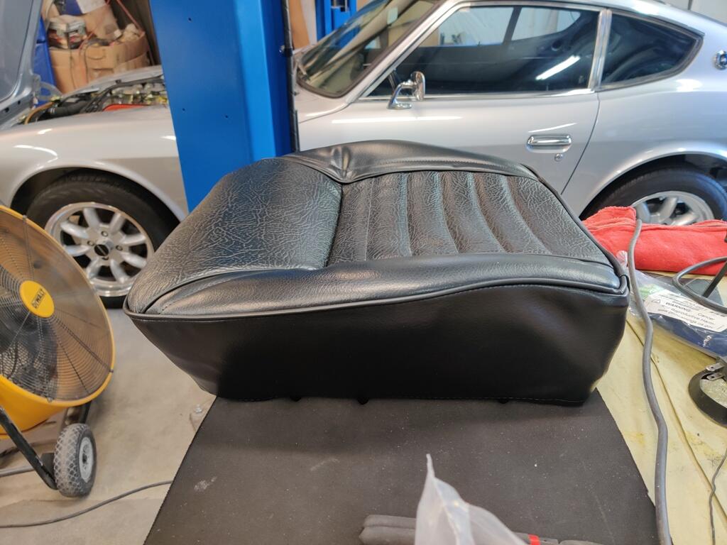
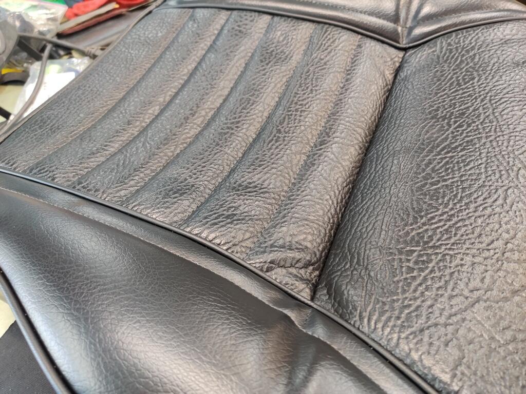
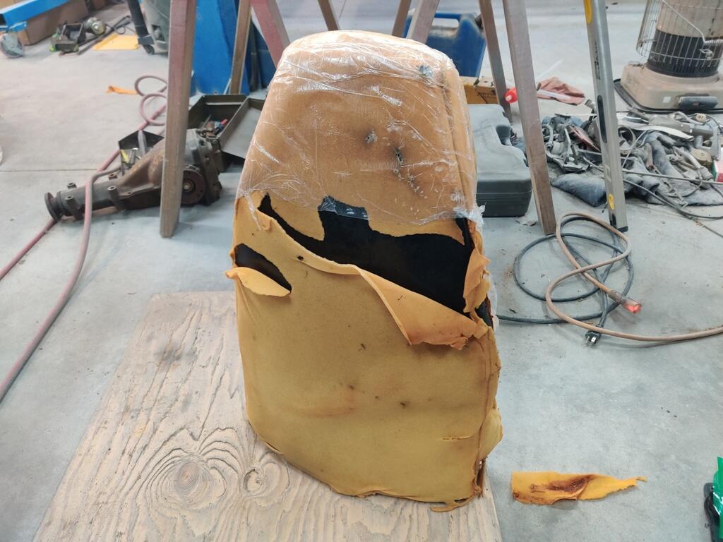
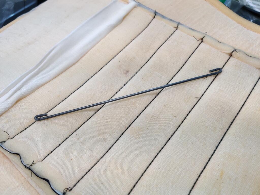
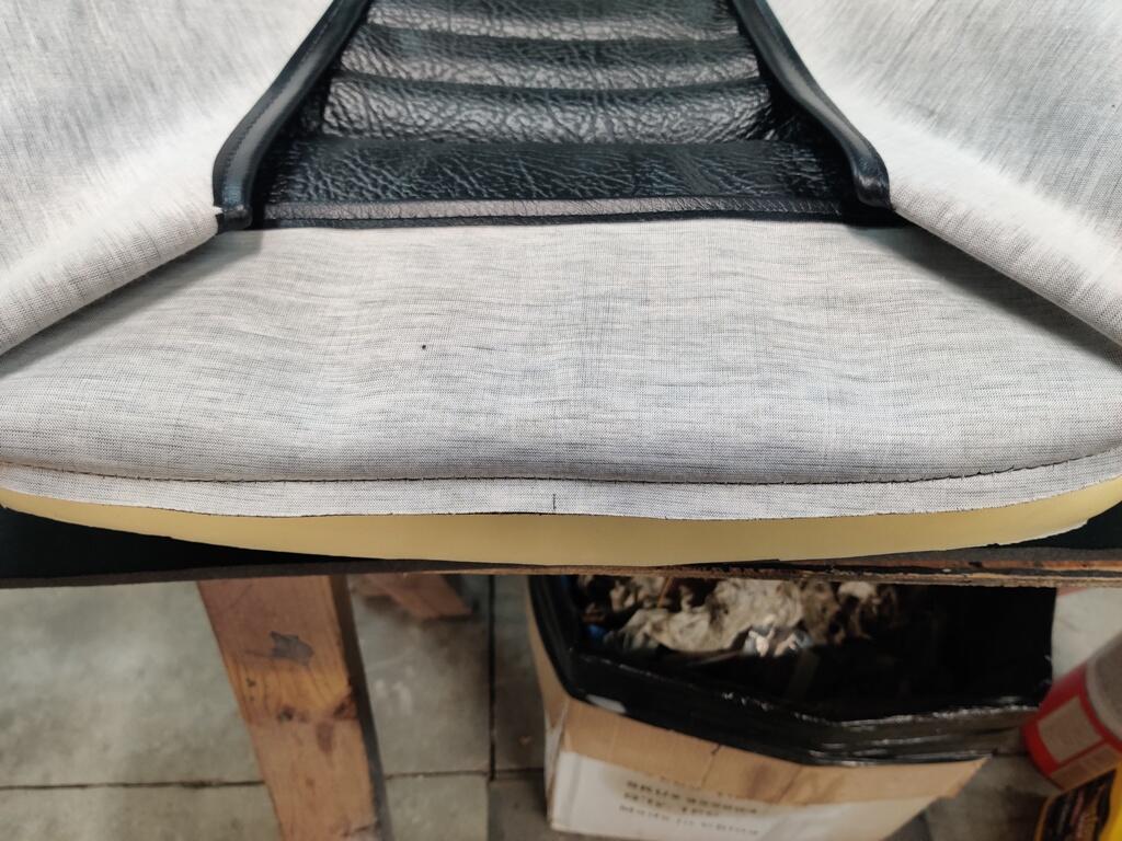
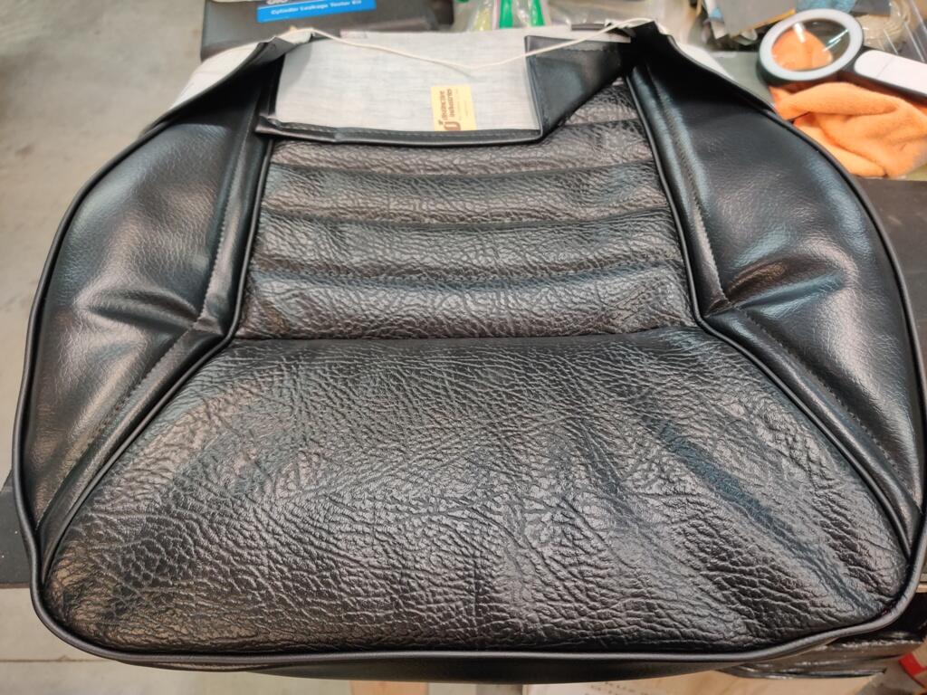
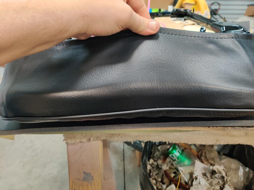
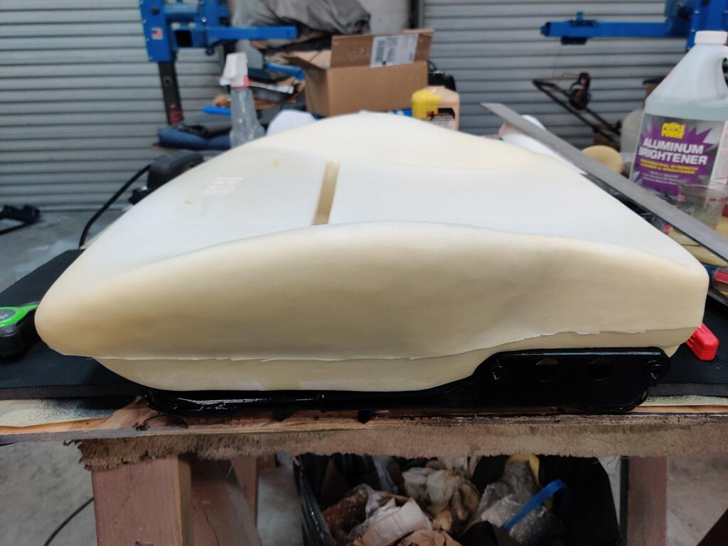
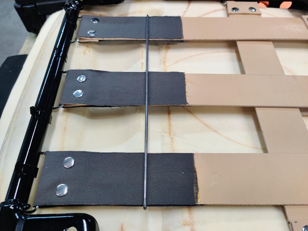
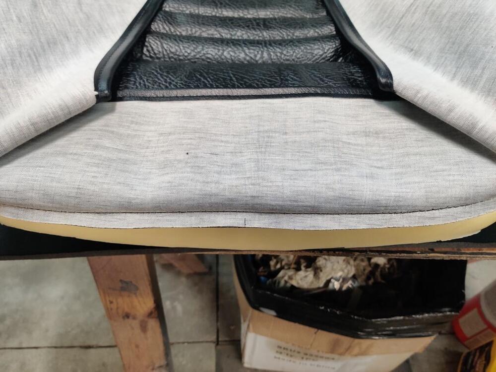
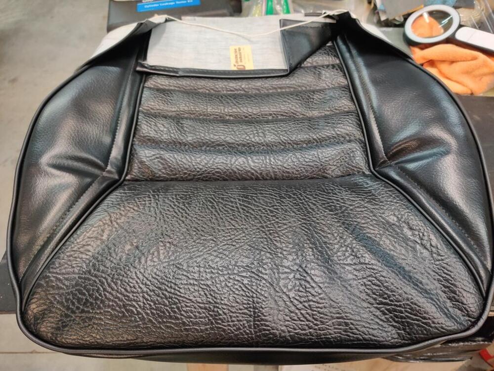
Today I set the car down on blocks under the tires to load its suspension so I could torque all of the suspension fasteners to factory specifications. Then I pulled the rocker cover to have a look at the cam and valve train. I was pleased to see that all looks good. Then I switched back to attempting to put on the seat upholstery. I worked with one seat bottom for quite a while. First, I made the decision to trim down the funky lip of foam at the front. I used as scroll saw to remove a portion of it from across the front of the seat cushion. Then I used some 36 grit sand paper to smooth out where I had cut it. I loosened the zip ties that are holding the upholstery to the seat frame. I still do not have any hog rings installed. Then I very carefully started working the upholstery onto the metal points/blades which are on the seat frame. I started at the front of the frame. I worked point by point from the front, around both sides. When I had the upholstery on all of the front and side points, I pulled on the cord that is inside the piping and this cinched the corners of the upholstery nicely. I tied this cord, (there is one each side) and tied them together. Then I installed a piece of wire in the piping of the back seat flap, and folded that flap onto the points which are on the back of the seat frame. I did not hammer the points down yet. So, I can still take the upholstery off and redo things. Finally, I pulled the zip ties so they are fully tight. Here is how it currently looks. I think it was the right call to trim the front of the seat cushion. I no longer have that odd bulge at the top front. But, pulling the zip ties all the way down, which I believe will be equivalent to when I install the hog rings, I still have the wrinkles in the top side panels. I don't care for them. I may experiment with adding some foam in this top side panel area. I started on one of the seat backs as well. From the factory, there were some vinyl pieces glued to the seat back on the edges: I checked location in my reference pics, and then made and glued some new ones in place. I believe the very thin sheet of foam that was on the backs of my seats was original. The new seat back upholstery from Distinctive Industries only has a pieced of reinforced vinyl for the back (of the seat back). So, I plan to install a thin layer (about 1/8") of the grey foam you see in the pic above to the metal seat back. And then install the upholstery over top of that. I have heard that it can be difficult to the install the upholstery on the seat back. I see that there was some very thin plastic originally as well. I may wrap the seat back (with 1/8" foam glued in place) in thin plastic also. I think the plastic will allow the upholstery to slide on easier.


-
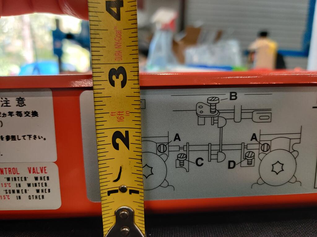
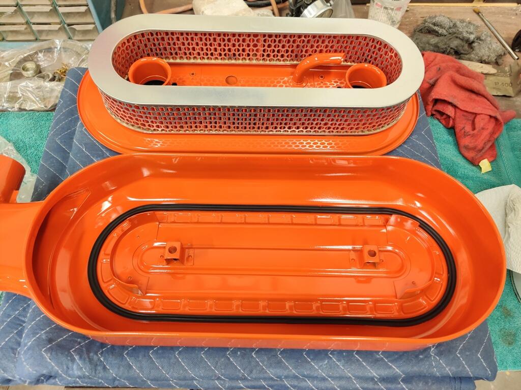
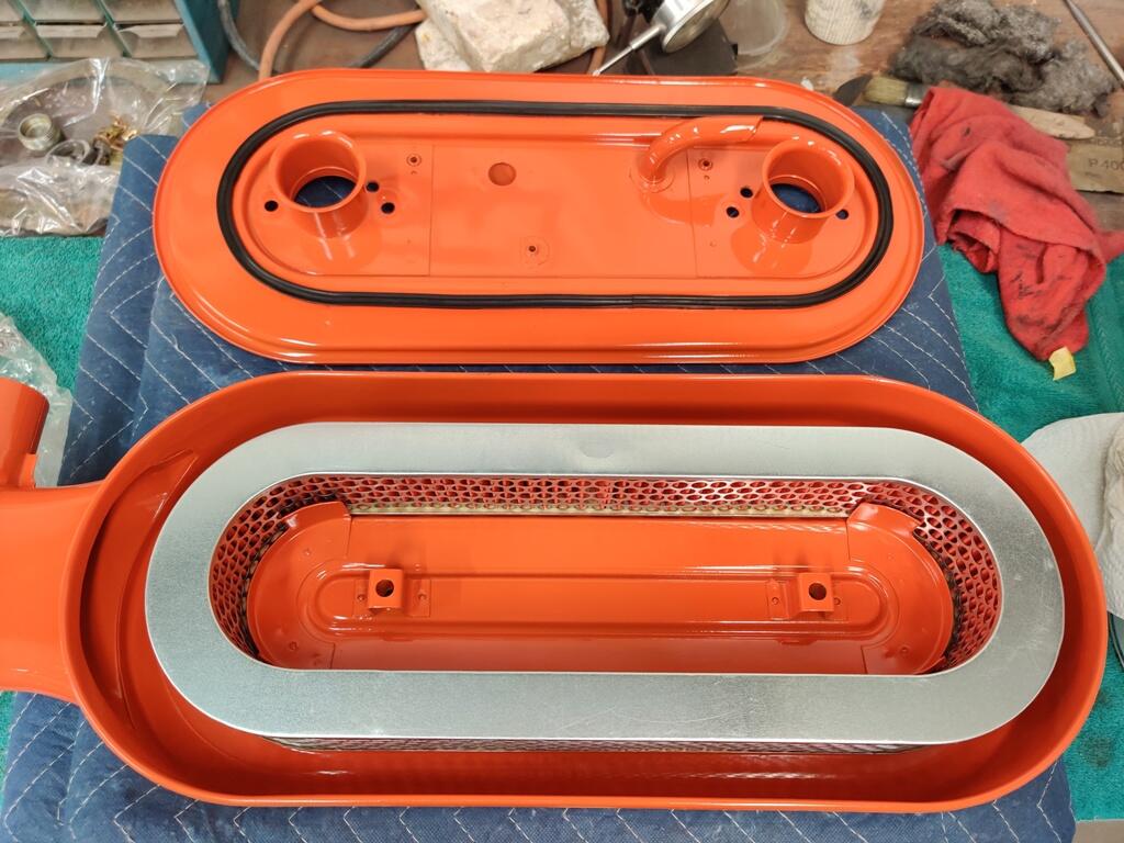
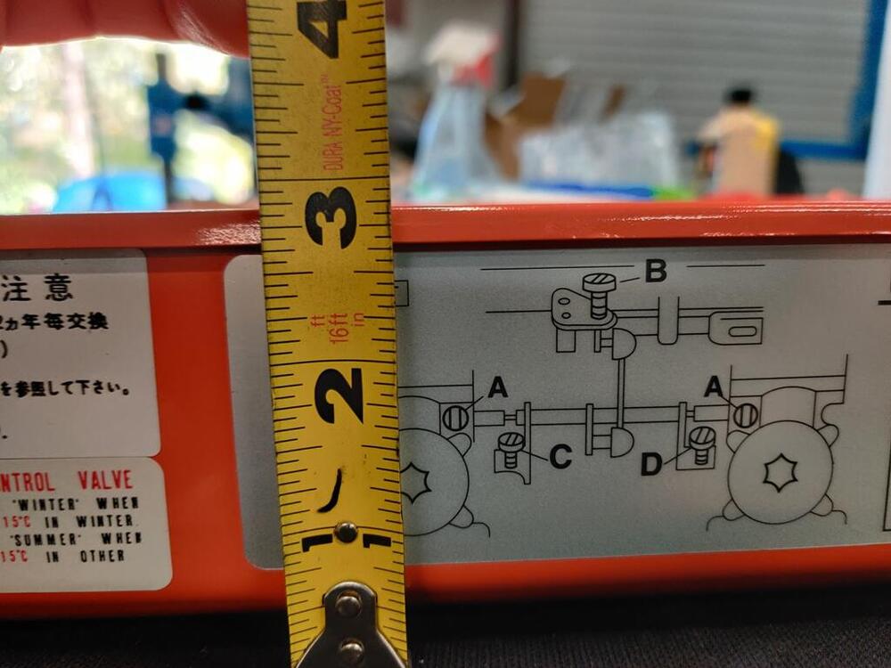
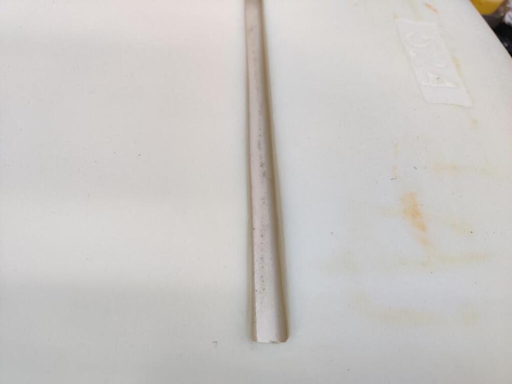
Yes! I took a few more measurements today. Outer filter case is not quite 2 7/8" from front surface to curled lip. With the filter sitting inside the outer cover, laying against the seal, there is only about 5/16" left of "depth" to the edge of the curled lip on the back. Filter is against seal on the back plate. So, again, when the cover goes on, seals are seating on both sides of the filter element, and leaving about an 1/8" inch gap between the seal and the curled lip of the cover. Is this the correct back plate?


-
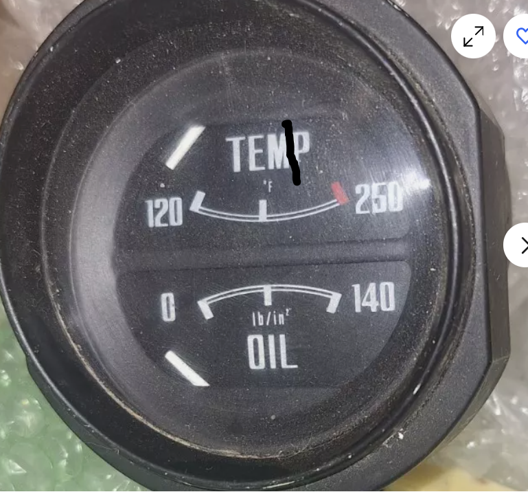
It's debatable if this raw video footage is more interesting than watching paint dry, but I was able to get the engine started and running for more than 1 min finally. The temp gauge was working its way well past normal, so I shut it down. I did grab my laser pointer and it was saying all was well - temp gauge was not. The needle was partly in the P like this: So, I decided to run it again and restart it to break in the cam at 2000 rpm for 20 min.
-
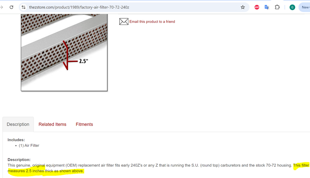
Wild. I found this on the motorsport auto site - it looks to me that the genuine filters are too tall now.
-
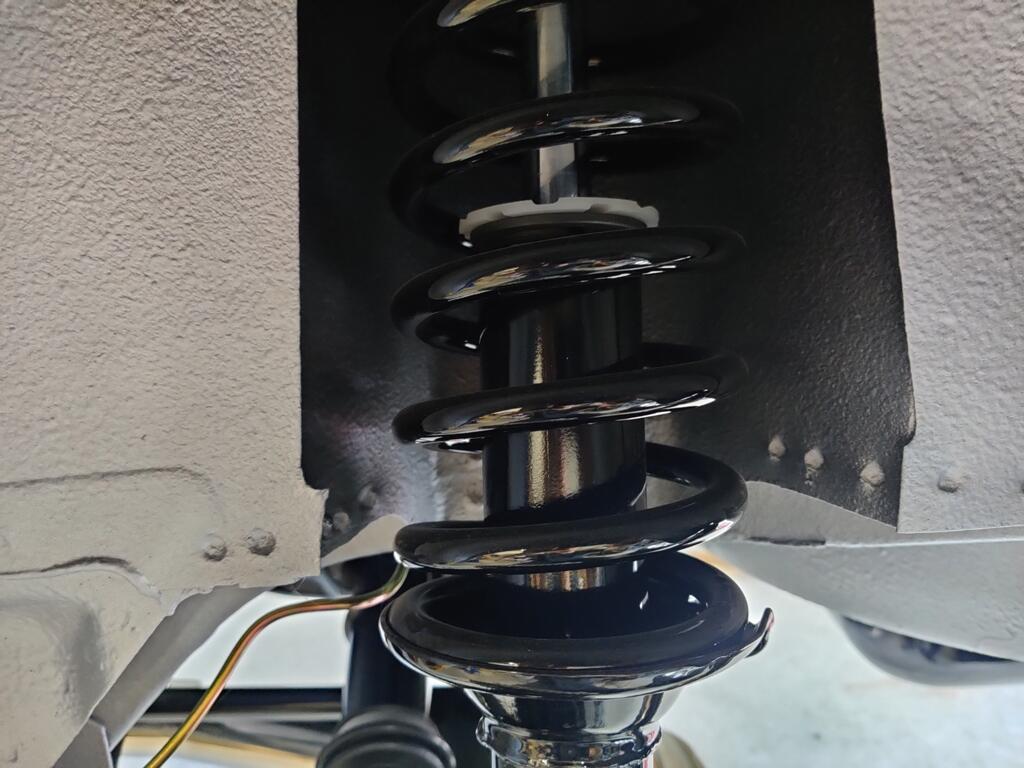
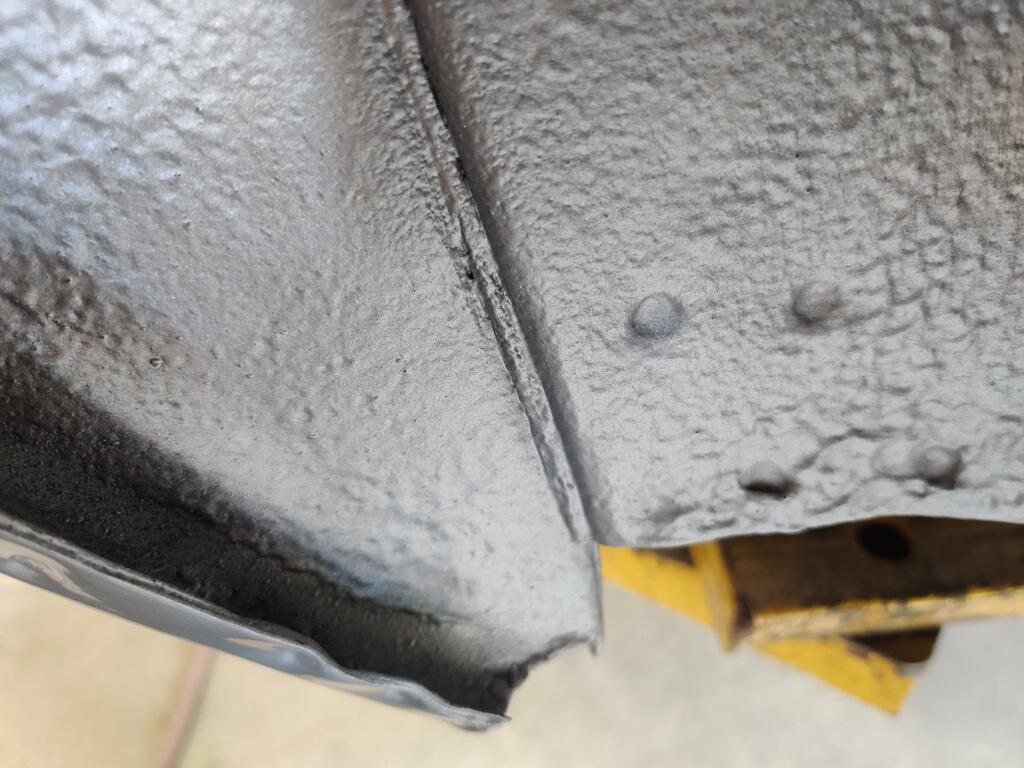
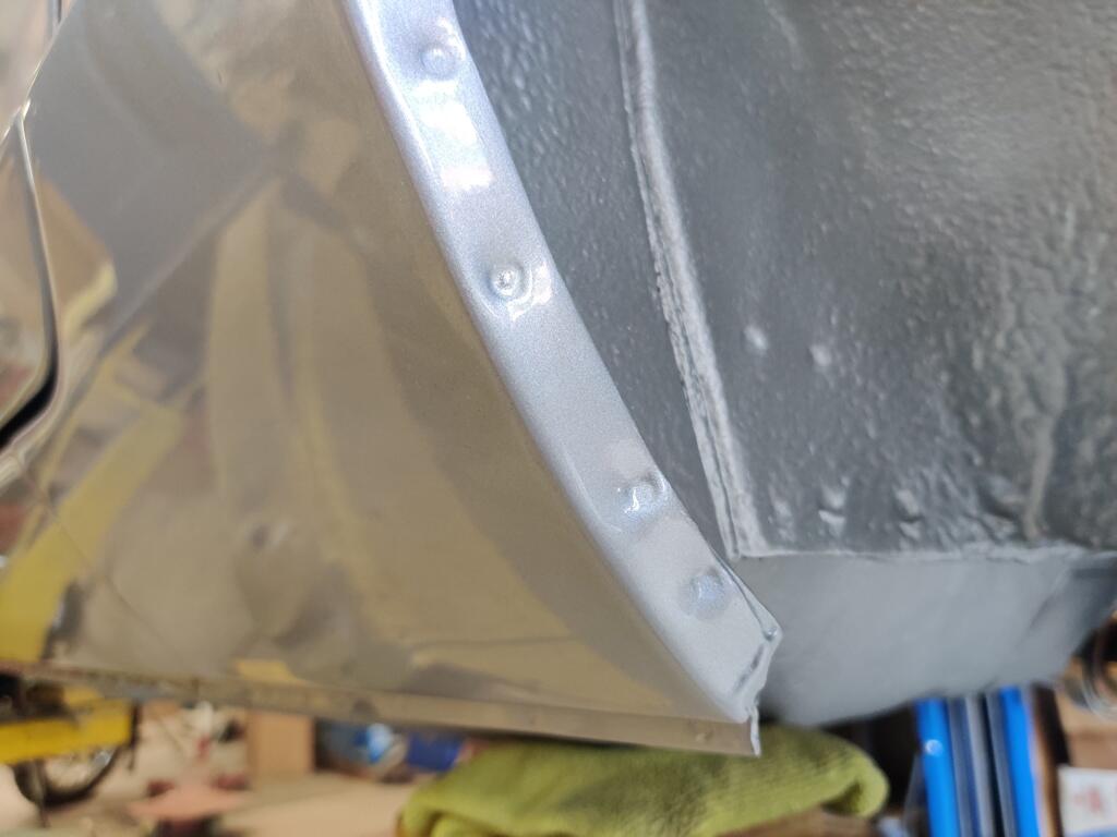
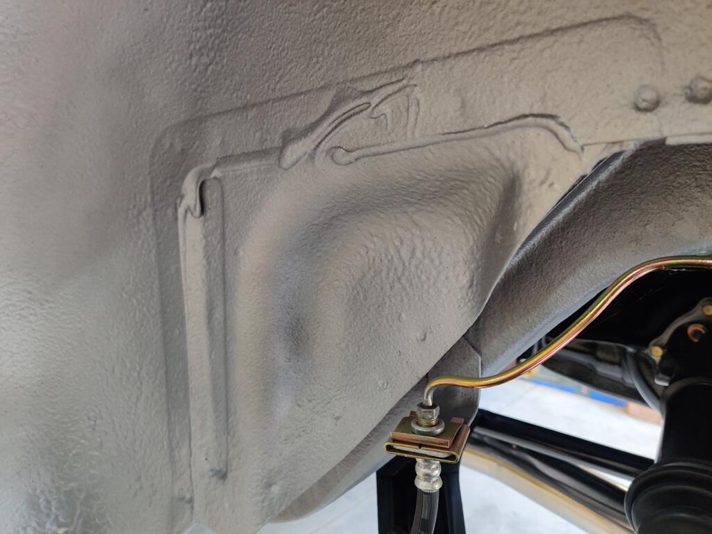
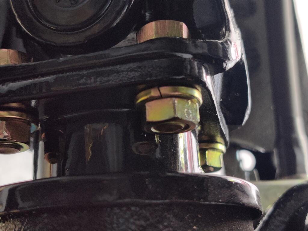
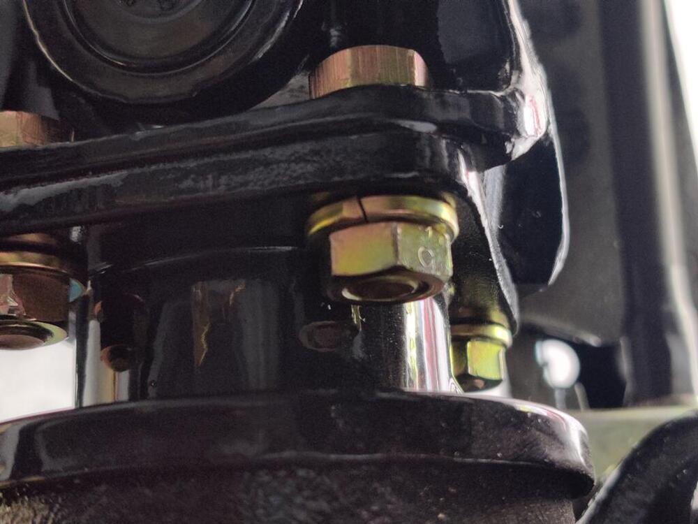
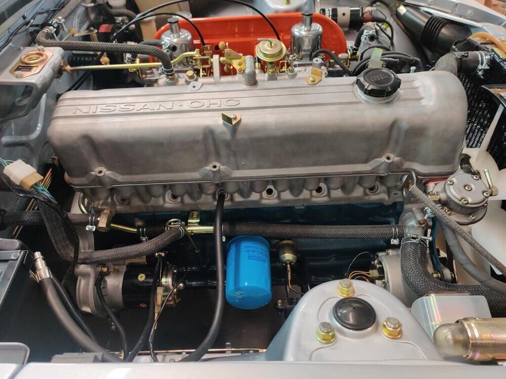
As I was working on the car this past weekend, I took a few pictures of some details. There are still a small number of not insignificant things to do, but I see that I am nearing the end. I expended a lot of effort to keep the factory spot welds in the lower dog leg part of the rear wheel opening. I am very pleased with this outcome. Replicating the original factory undercoating didn't go as well as I would have liked. However, I do like that some of the old shows through and not in a way that it is obvious that there is old and new: I painted the aftermarket Suspension Techniques springs black so it would not be obvious that they are not original. I disliked the bright blue they were originally. Original rear drive shaft installation hardware - note the "9" stamped into the side of the nuts: The modified spring retainers should arrive back to me tomorrow. After I install them and check cam wipe patterns, I should be able to fire the engine up and break in the cam.


-
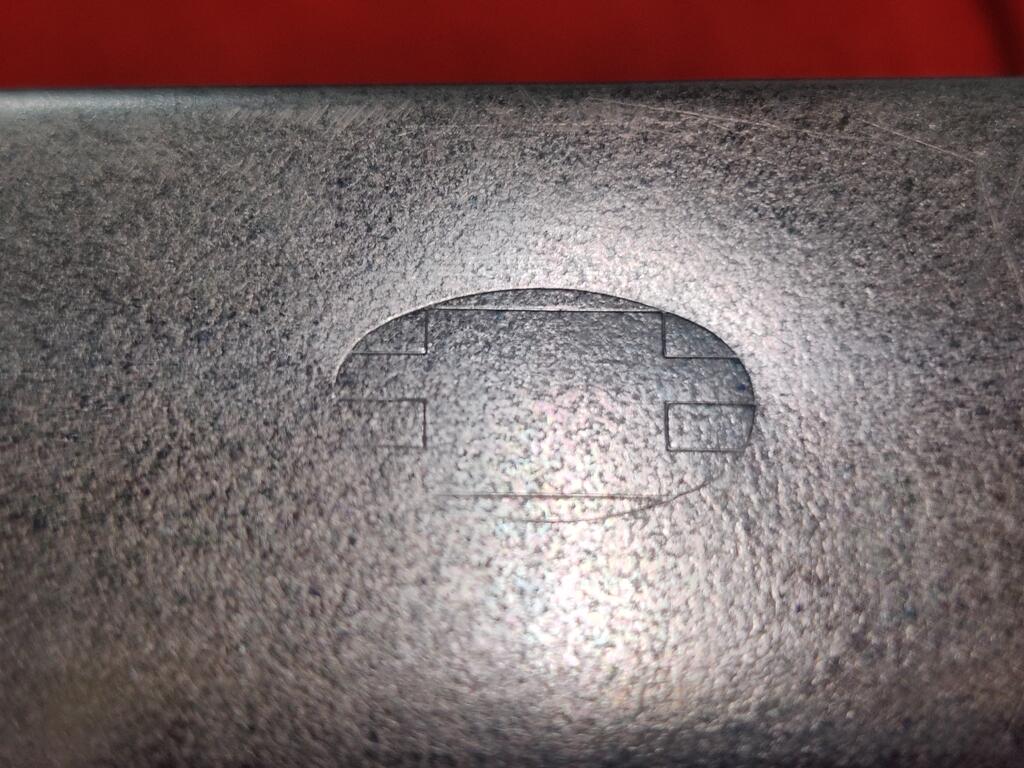
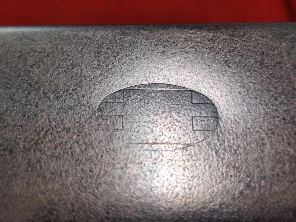
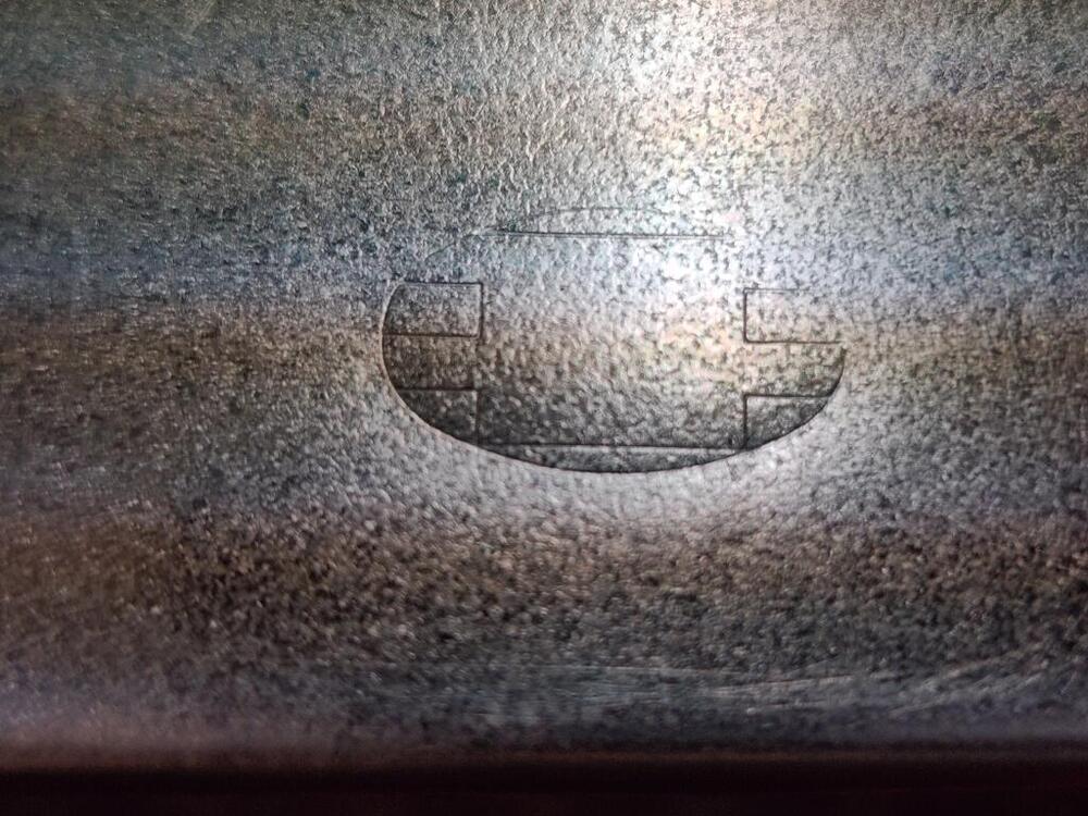
Here are the markings on my air filter element - there is one of these stamps on each side, and the U8308 is only on one side of the element:

-
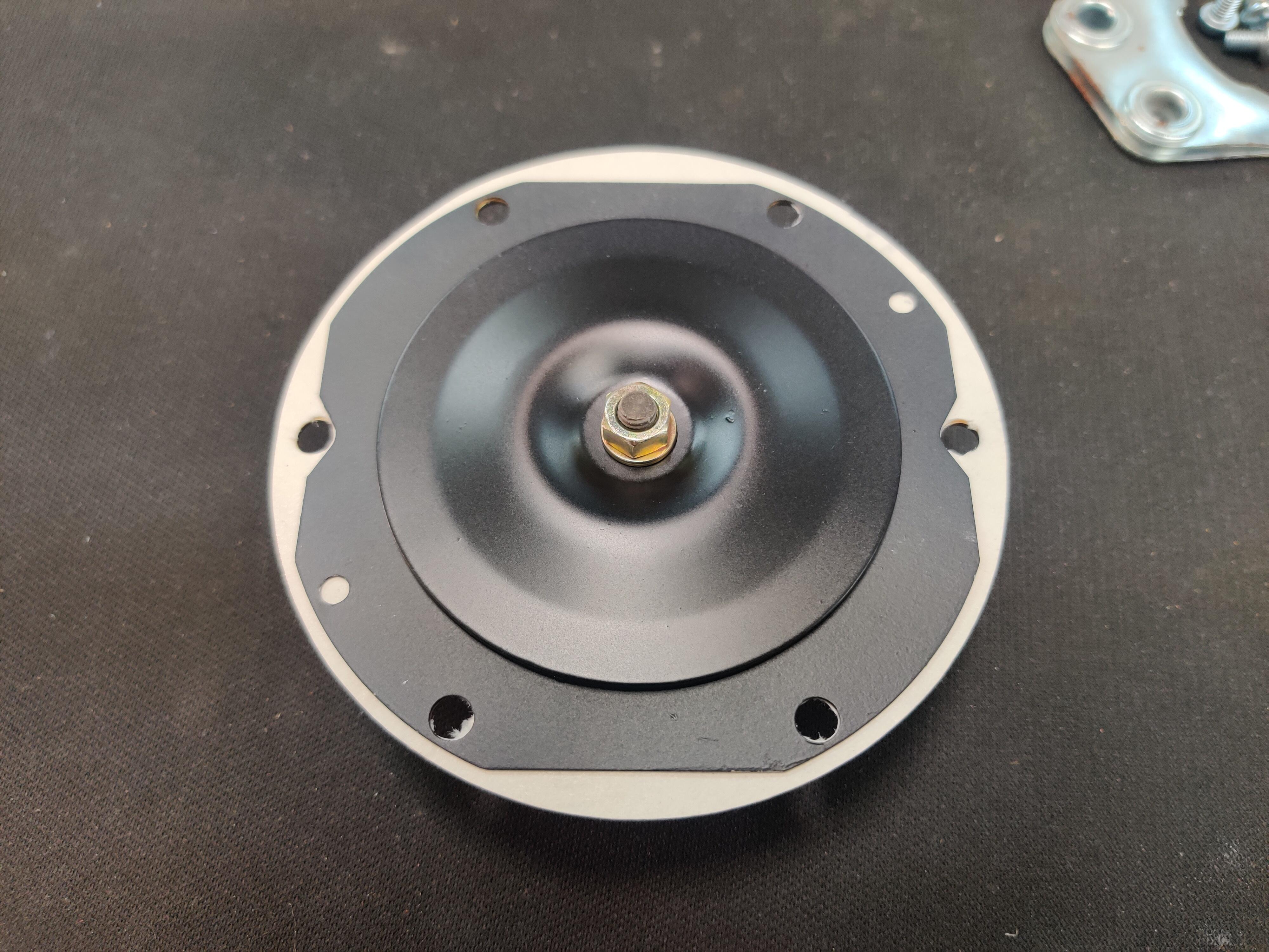
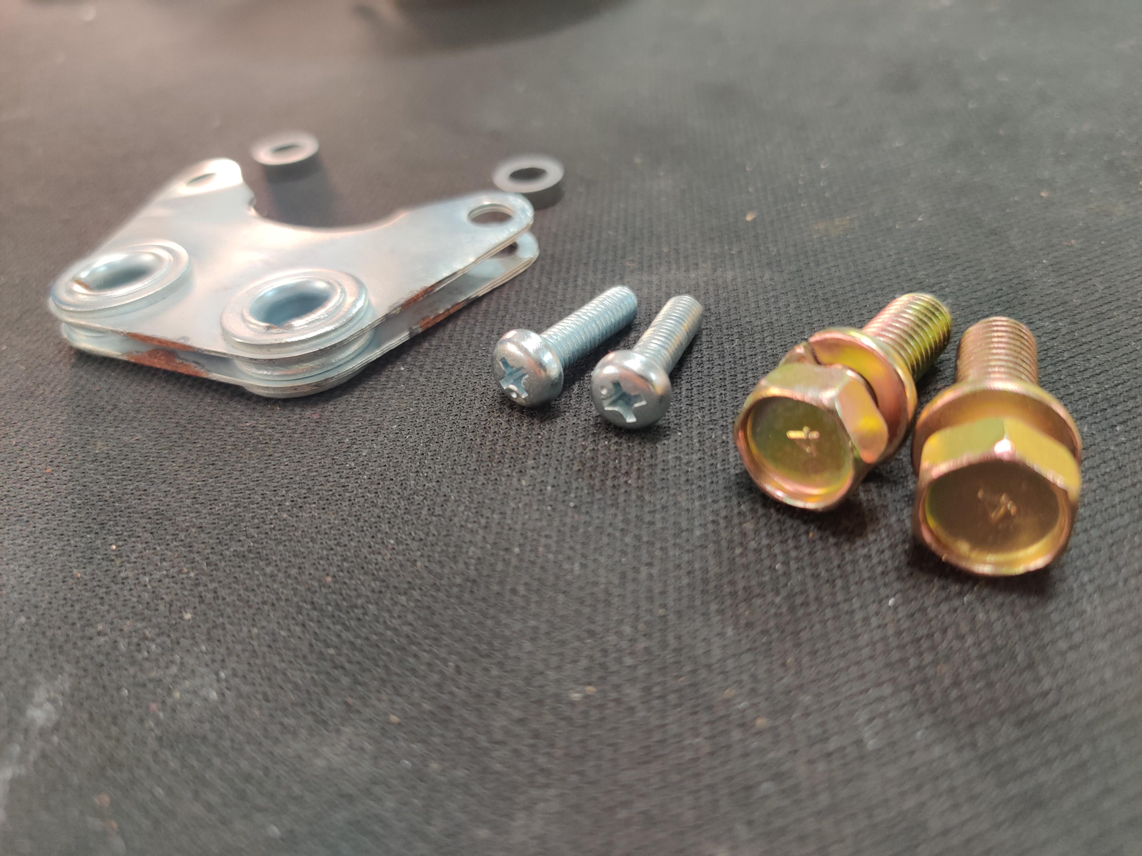
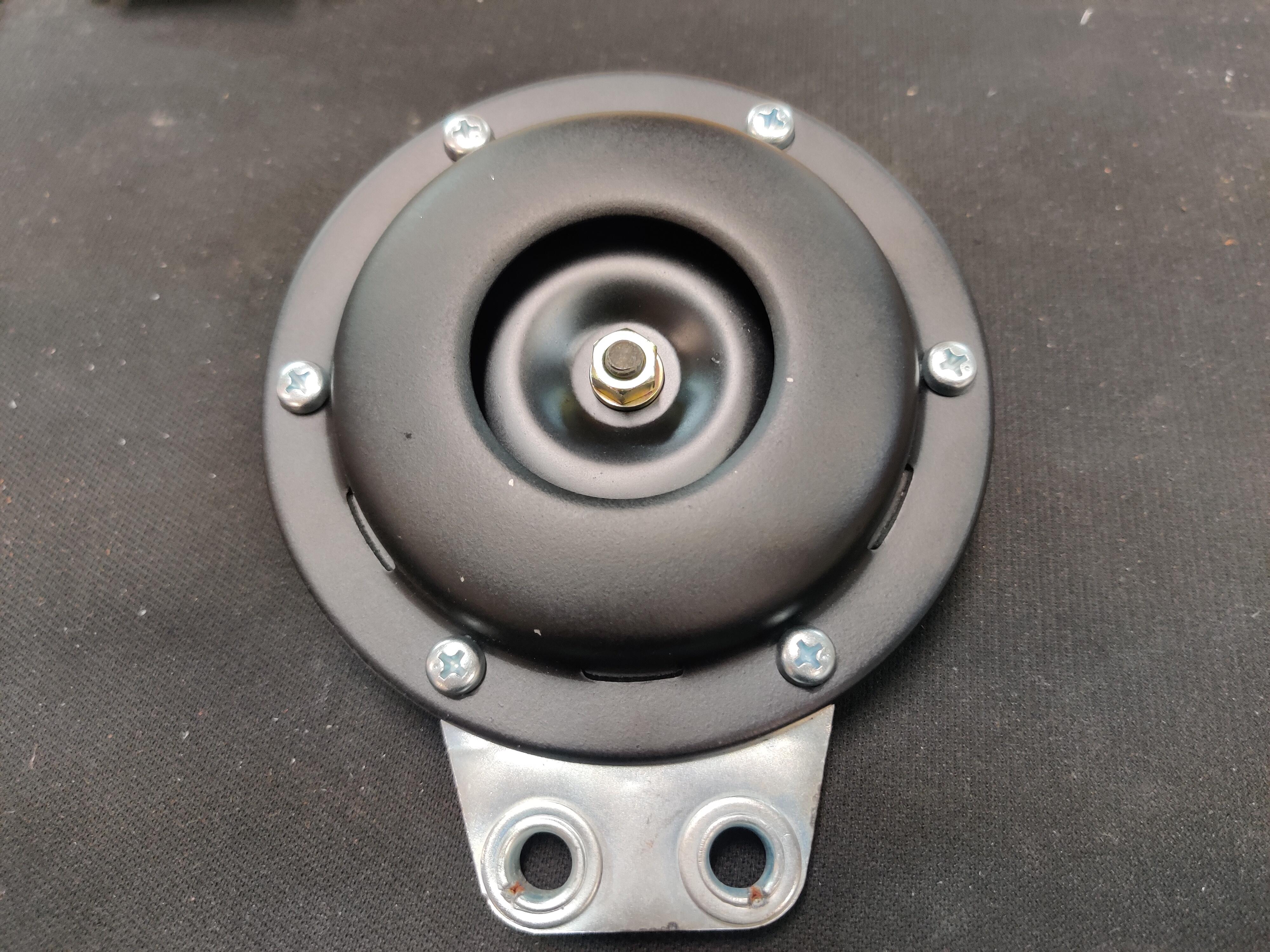
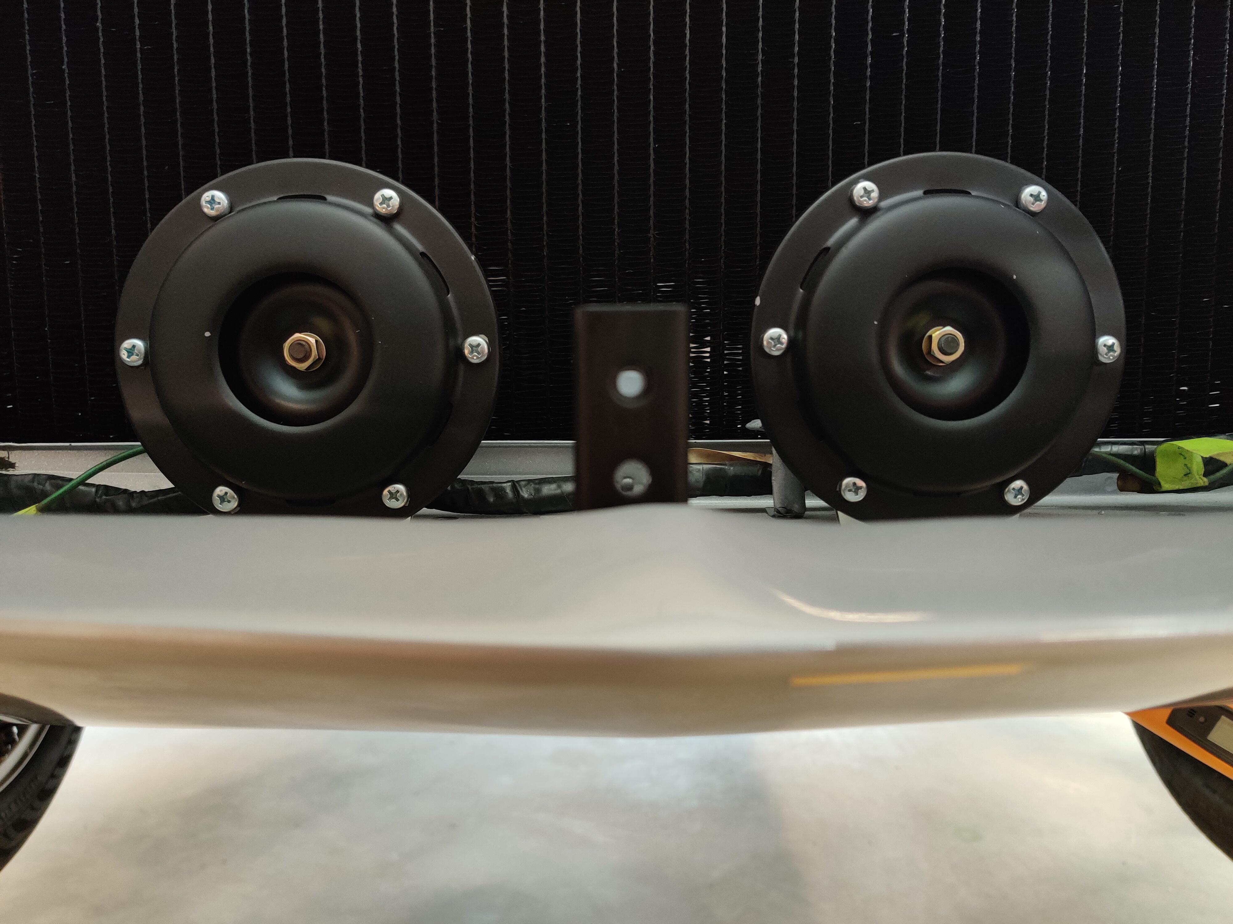
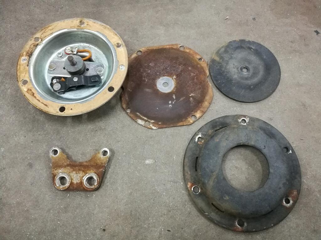
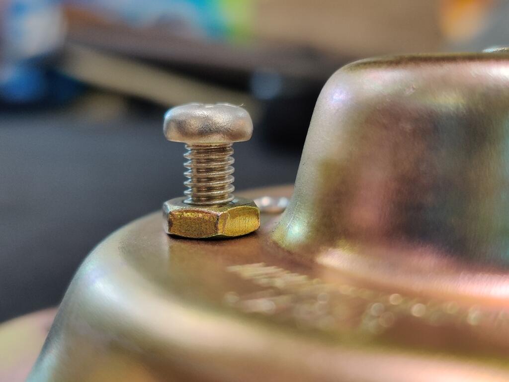
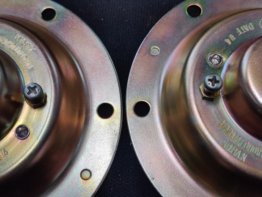
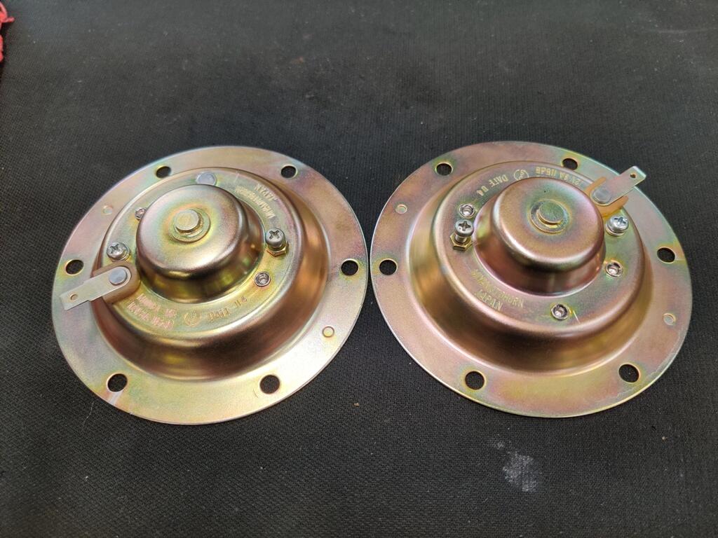
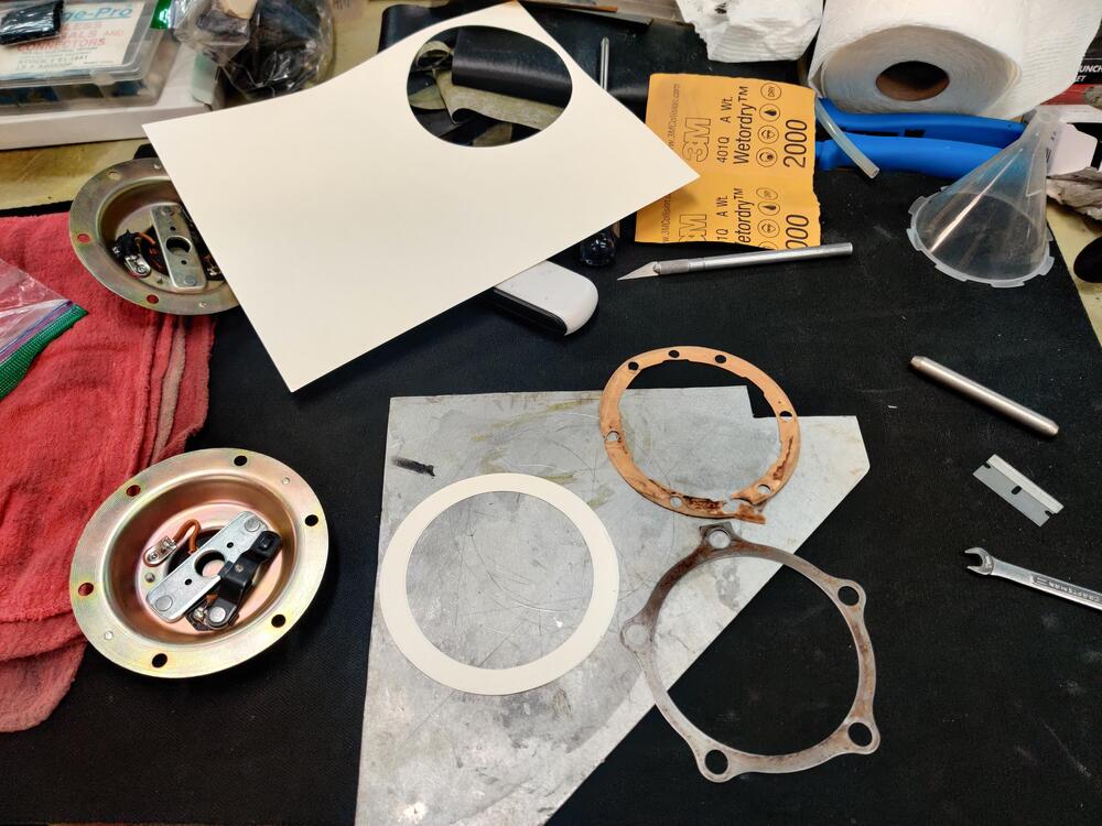
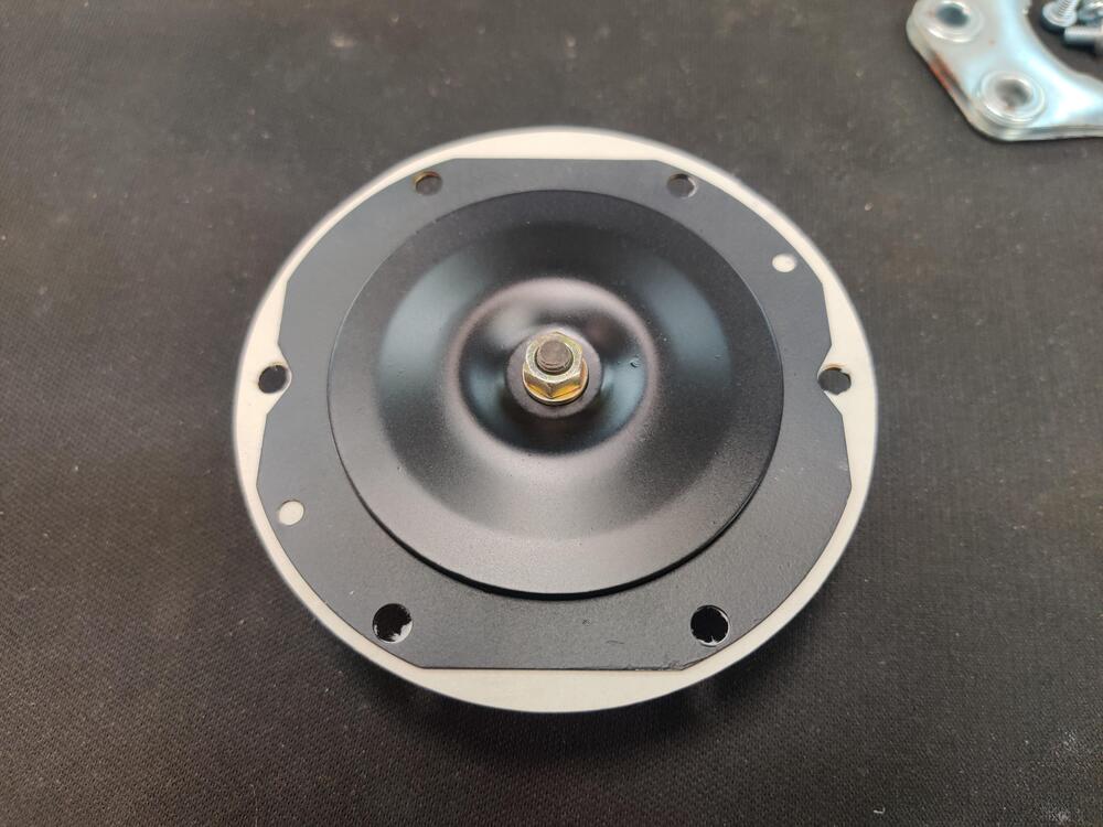
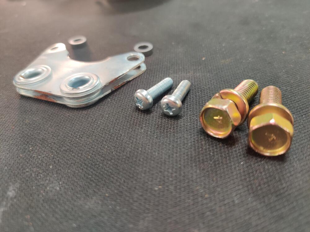
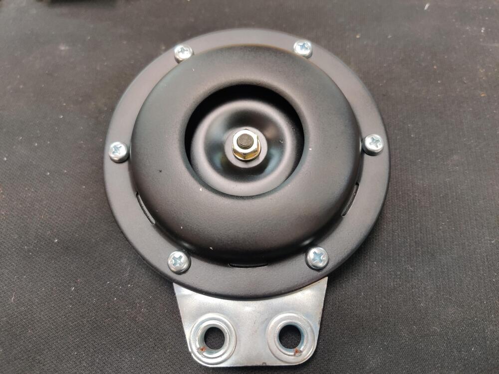
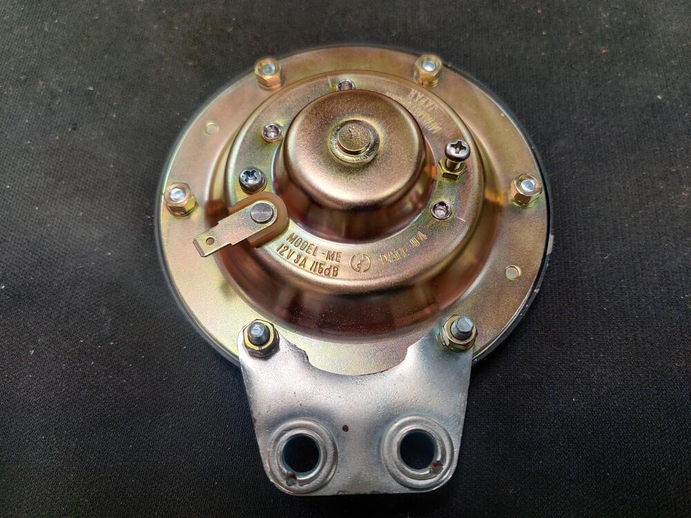
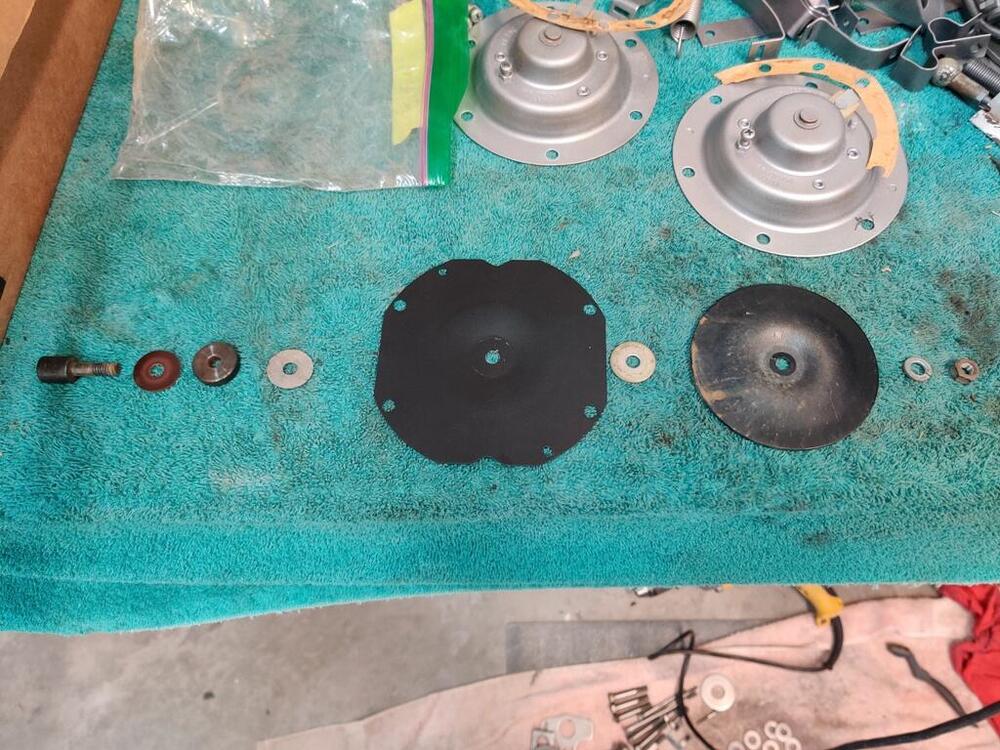
Today, I finished reassembly and testing of the horns. I made some gaskets out of some old "resume" paper I had. It is high quality paper in a slightly off white color. I sprayed a couple of coats of clear coat from a spray can on each side of the new gasket. The differential side flange shim was a good template for the ID. I used the horn for the OD. Some people have said that their horns have a very dark brown finish on the front. Some have said they were other colors. Mine sure looked to be black to me. Condition the horn was in when I took it apart. This plate is aluminum and was painted black on one side. That paint looked to be done at the factory to me. I cleaned it and resprayed it with Krylon semi-flat black. I forgot to take a picture of all the hardware, but here is some of it. The mounting bracket has two little aluminum spacers that go in between the plates. Two longer 6 mm screws secure the mounting bracket to the horn. The other four 6 mm screws are much shorter. Horns installed. It is interesting what makes the horns high vs. low pitch. I think all of the parts are the same except perhaps the piece to the far left in this picture. I think the height of it is different for each horn. And to get the contacts operating properly, the volume adjustment screws have to be set differently for each. I found this out by having to adjust my volume screws differently from what I did yesterday. The screw that was tall, I had to make short. And the screw that was short, I had to make tall. It was an interesting learning experience, but now they are both adjusted and nice and loud.


-
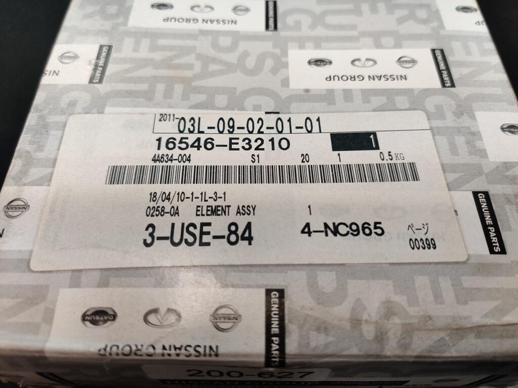
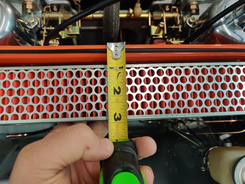
Where do you see 800-627 on the end? Oh. I see the 800-627 on the end now. Interesting. I thought I purchased this from a Nissan dealer. However, the Nissan part number on the box is correct for up to 06/1972. The filter I have is 2.355" thick as measured with calipers in several places. That is 59.8 mm thick. So, do I have the wrong filter housing?
-
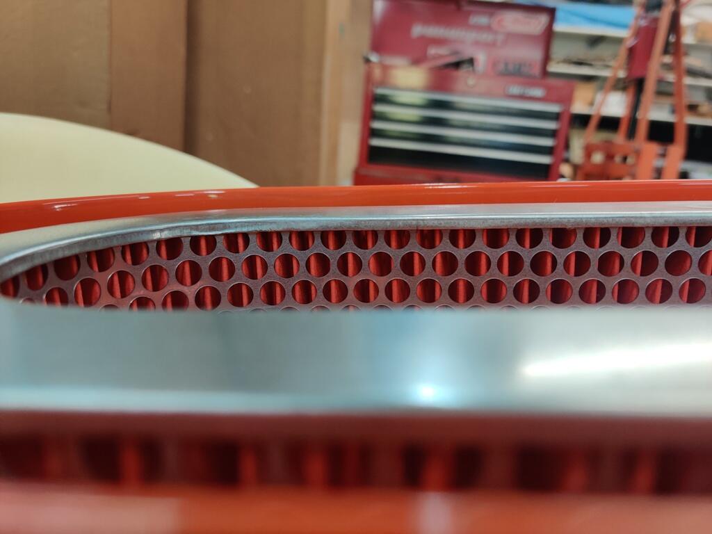
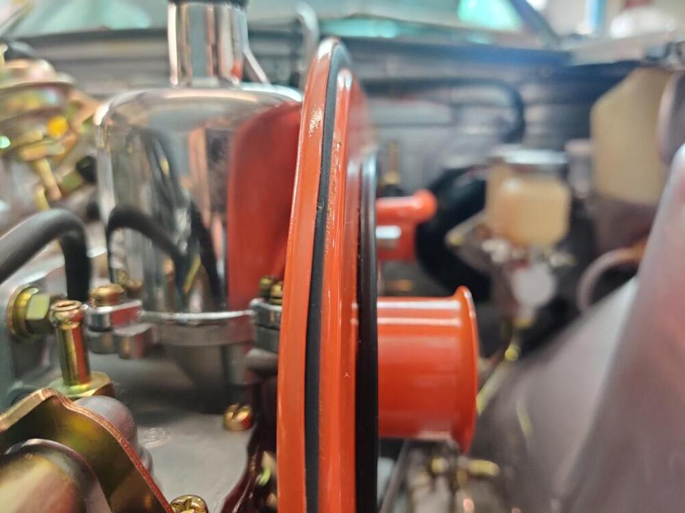
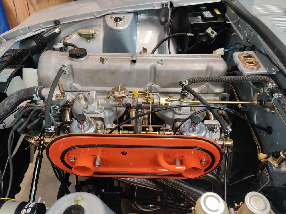
Has anyone else seen that their air filter housing does not seat fully against the seal even with an OEM air filter installed? I painstakingly refurbished the air cleaner housing. I re-used the rubber seals inside. The only replacement seal is the one that goes all the way around the periphery that is not making contact with the cover in the photos above. That seal came from Banzai. There is a gap of about 1/8" there - the outside periphery of the air cleaner cover is not touching the seal. The seals on the inside of the air filter back plate and cover are bottoming out on each side of the air filter. Is the factory air filter a bit thicker than the original?


-
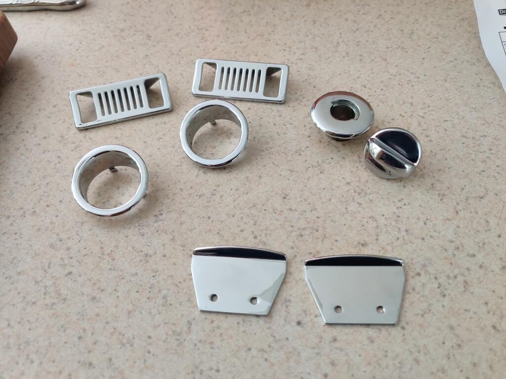
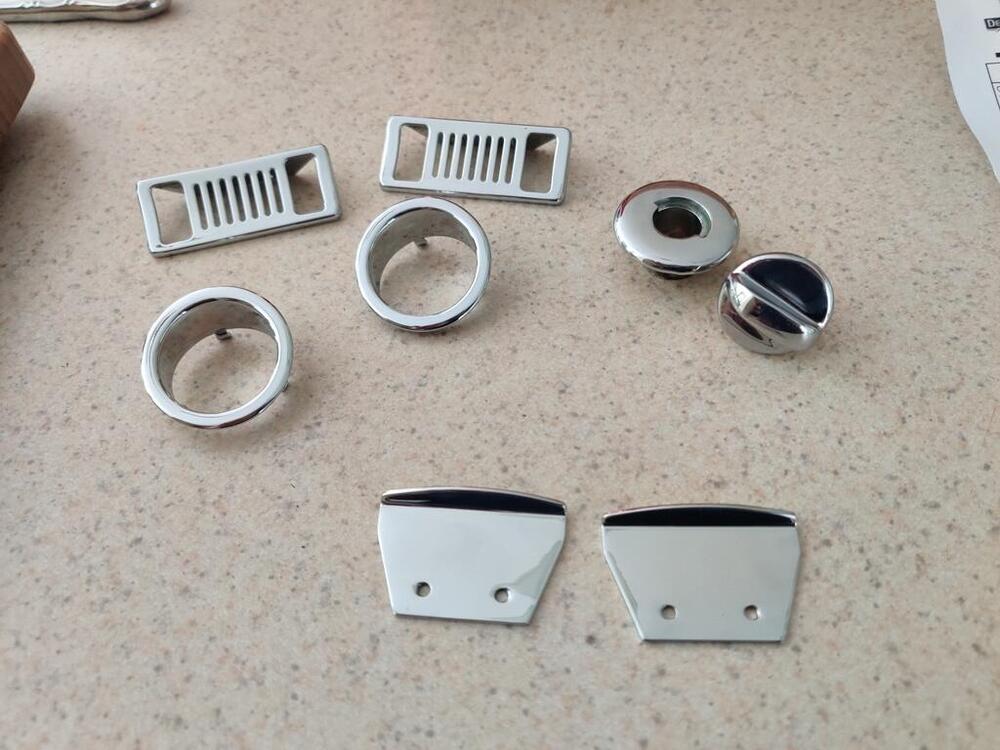
I am pausing on the seat bottoms for now. I need to think about how to make them look right. It is going to require something other than just hog rings to secure wire in the flap to the wire under the Pirelli straps. More distance will be required to keep the material from being yanked down too far. In the meantime, I got the small parts back from the chrome plater. They came out nicely. These cost about $250 to have redone. Before removing the horn tone adjustment screws, I took some reference pictures: Today, I put the re-plated parts back in the horns: I attempt to put the adjustment screws back in their original positions. Now I just need to make some gaskets out of paper so I can finish assembling them and then test them out! I also was able to remove the rest of the exhaust valve spring retainers early this past week and get them shipped off to the guy that did the head for me. He turned the retainers in a lathe to shorten the "hats" and will get them coming back to me on Monday.


-
I think there may be another. I don't see the numbers in these cushions like on mine: https://interior-innovations.com/product/datsun-replacement-seat-cushions/
-
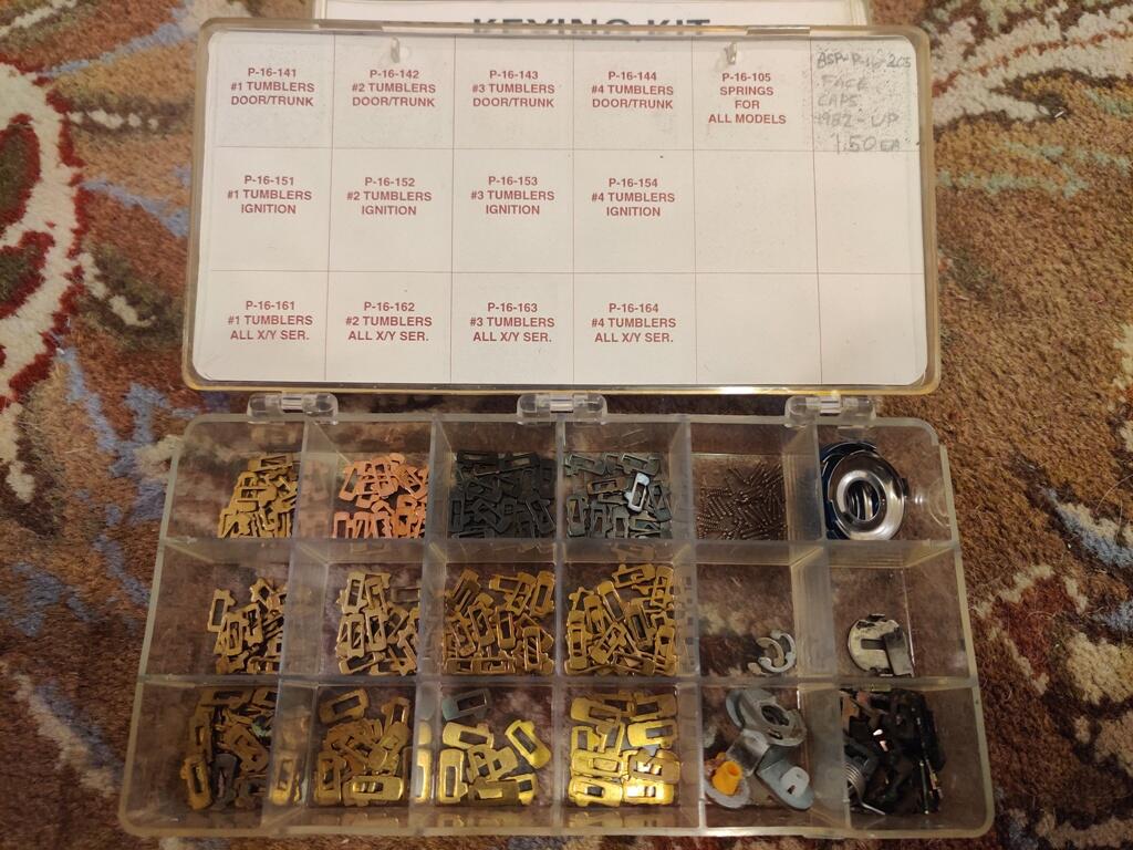
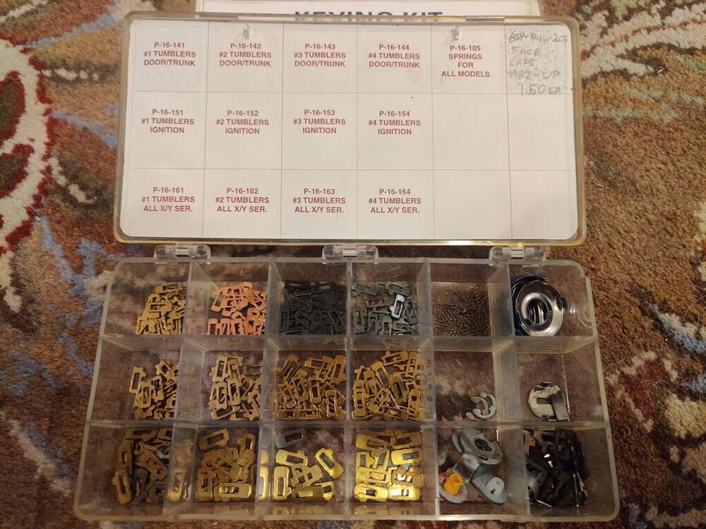
Correct. The wafers for the ignition have a slightly convex edge on the bottom or top (can't recall which). If you look closely, you can see that in my pictures. If you start with two door locks that are keyed to the same key, you save yourself a fair amount of work when replacing the covers. The thought crossed my mind that I could sell you some of the wafers which might be a good option instead of waiting for the kits to show up for sale. I could send you a few of each size and you could map out what you need. Let me know what you think.
-
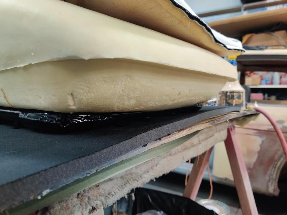
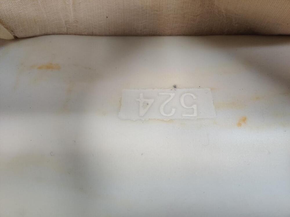
Thanks Keith, I worked on the one seat bottom for a couple of hours today. I made a rod for the flap and used my Exacto knife to put holes in the foam and run zip ties through. When I cinched them all the way down, I did not like what I saw. None of the edges of the upholstery are attached to the frame, however the amount the seat upholstery got "pulled down" in the center seemed to be excessive. I couldn't really get pictures while doing so, but even pulling very tightly and holding the upholstery down along the front and sides, the creases in the side panels on the seating surface would not go away. I also found myself examining the front of the foam closely and not liking what I was seeing. The front of the upholstery is a simple, flat piece. Why is there a step here in the cusion? The step causes the flat section of vinyl to bulge. I don't like it. When you pull the front really tight, that lip basically crushes and becomes far less noticeable, but why is it there at all? So... I suspect that this is not the foam I should be using with my upholstery. The upholstery kit I have was made by Distinctive Industries. And the foam, (though when I ordered it, I asked if it was made by Distinctive Industries and was told yes), I think was made by Seatz. I purchased the foam from Motorsport Auto. And doing a lot of searching online, I keep seeing that they use Seatz as their supplier. See the numbers cast into the foam - can anyone confirm that this foam was not made by Distinctive Industries?


-
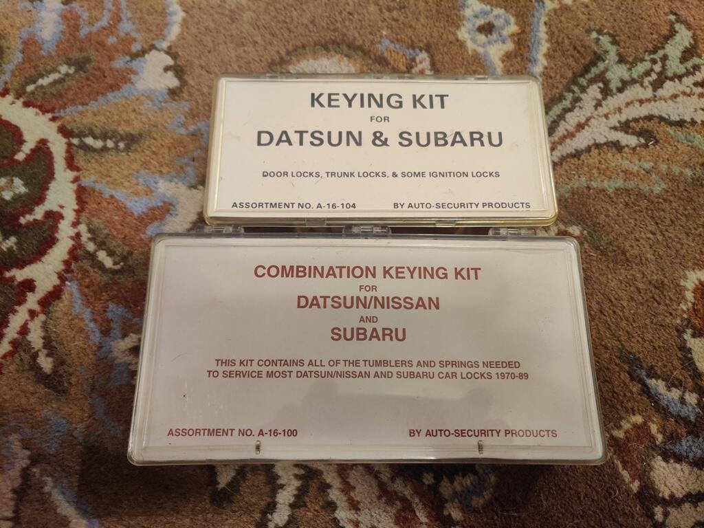
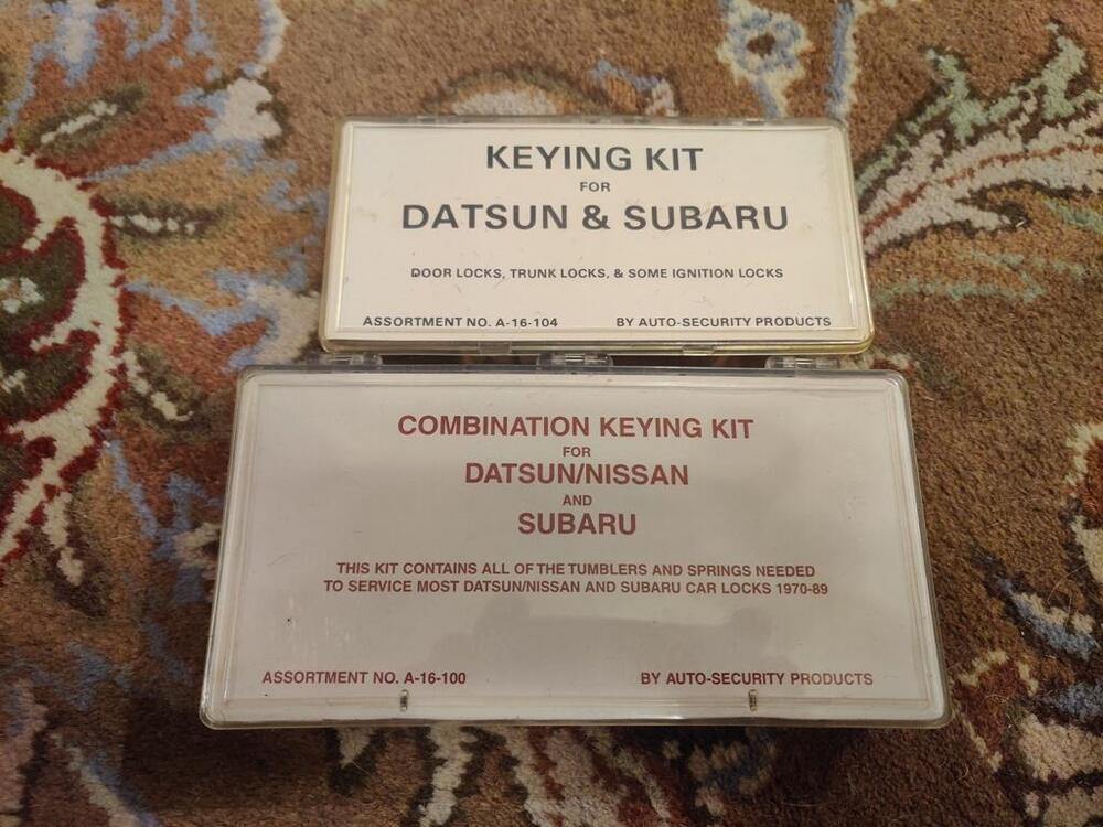
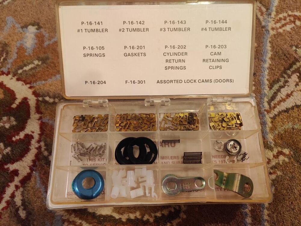
All of the locks on the car use wafers, but the wafers for the ignition are slightly different. These are the kits I bought and their contents. The A-16-100 has both types of wafers. The A-16-104 only has the wafers for the locks other than the ignition.
-
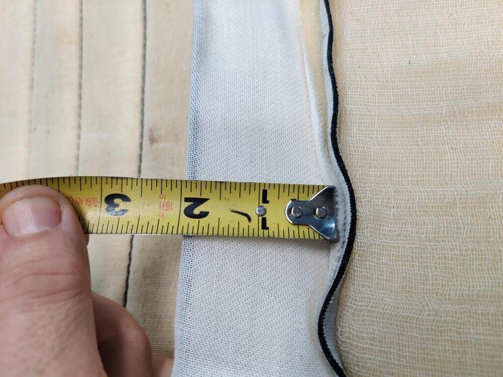
Thanks Keith. Do you have any thoughts or concerns about the flap being only 2" deep and the and the additional distance that flap needs to be pulled down to reach (within hog ring reach) of the wire running across the bottom of the Pirelli straps? Also, I went looking for Imperial Army green, but only found some acrylic hobby paint. Do you recall what you actually used? I'd like to use it in a couple of places on my seat rails to improve their appearance a bit. Garrett
-
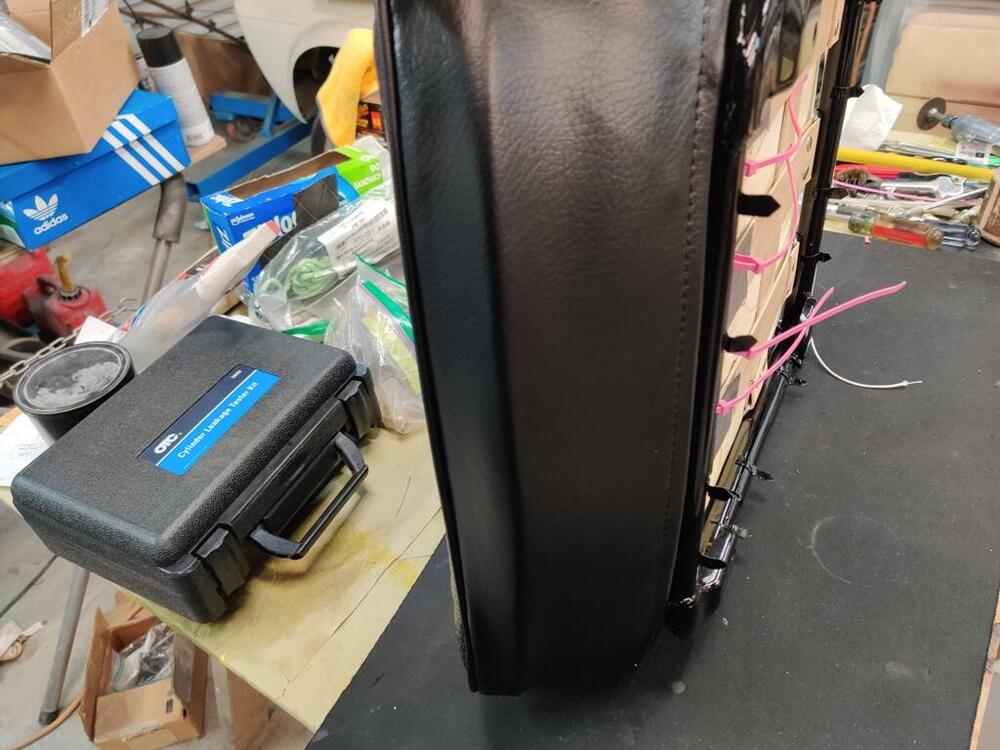
I was able to find kits on eBay and rekey my locks. I did all of them including the glove box. In my case, I bought a new ignition lock because mine was worn... and I bought a new hath lock that came with the original black keys. Then I rekeyed the ignition and the doors and glove box to match. At and following posts here provide some details. More are elsewhere in my build thread. Here is another, for example. Be careful when buying new door cylinders as most I have seen come with their own key - they do not use the same key for both. You have to find two locks that come with one key which seems to be rare.
-
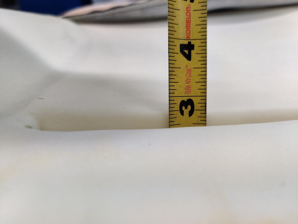
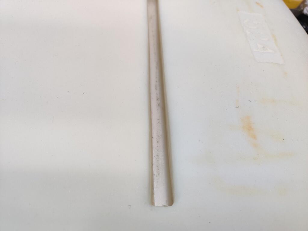
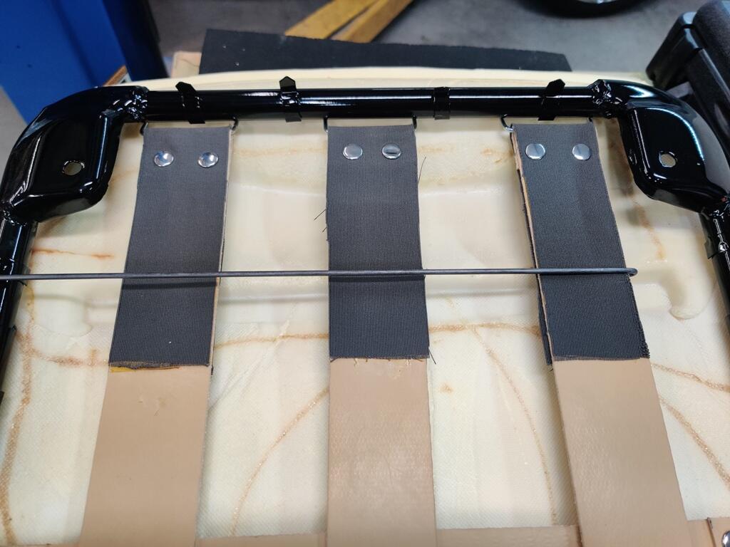
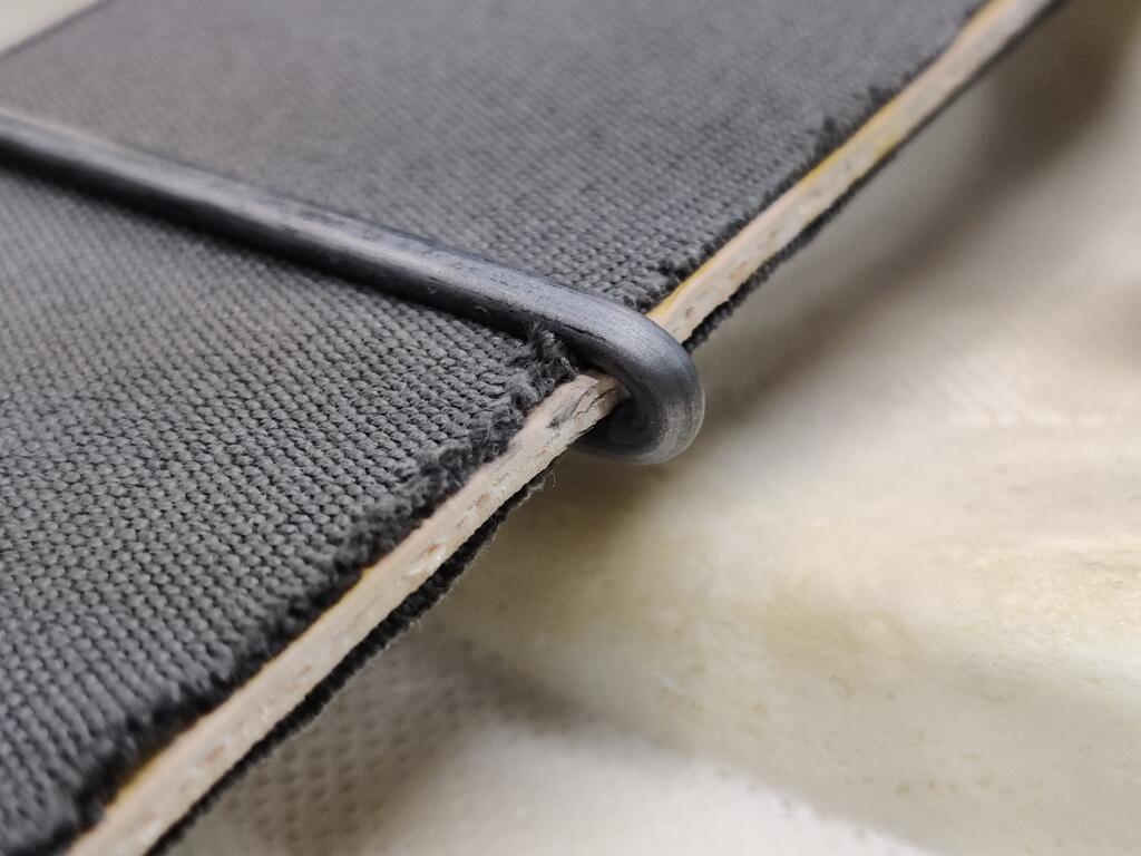
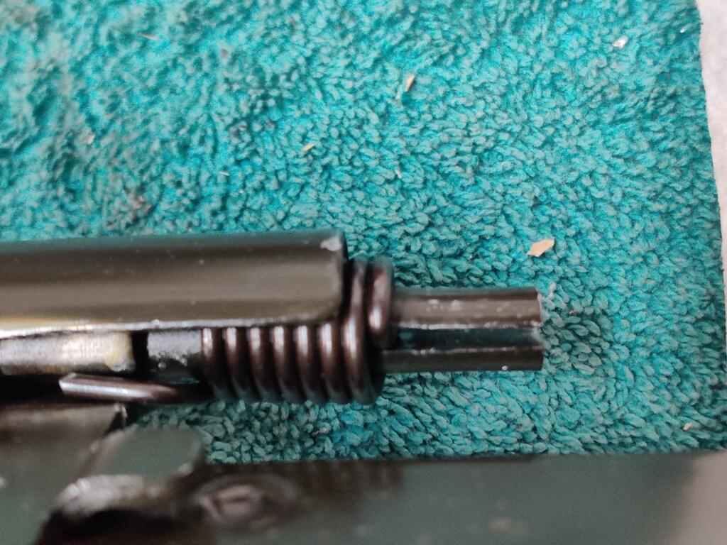
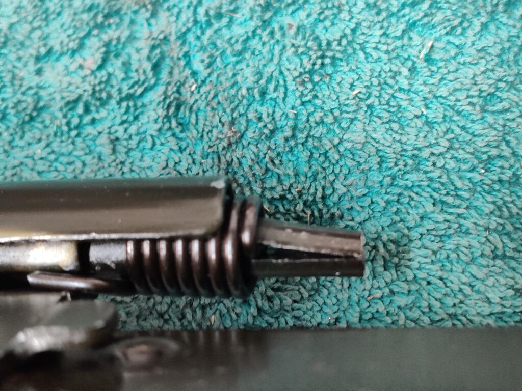
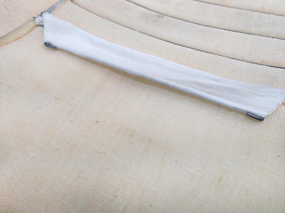
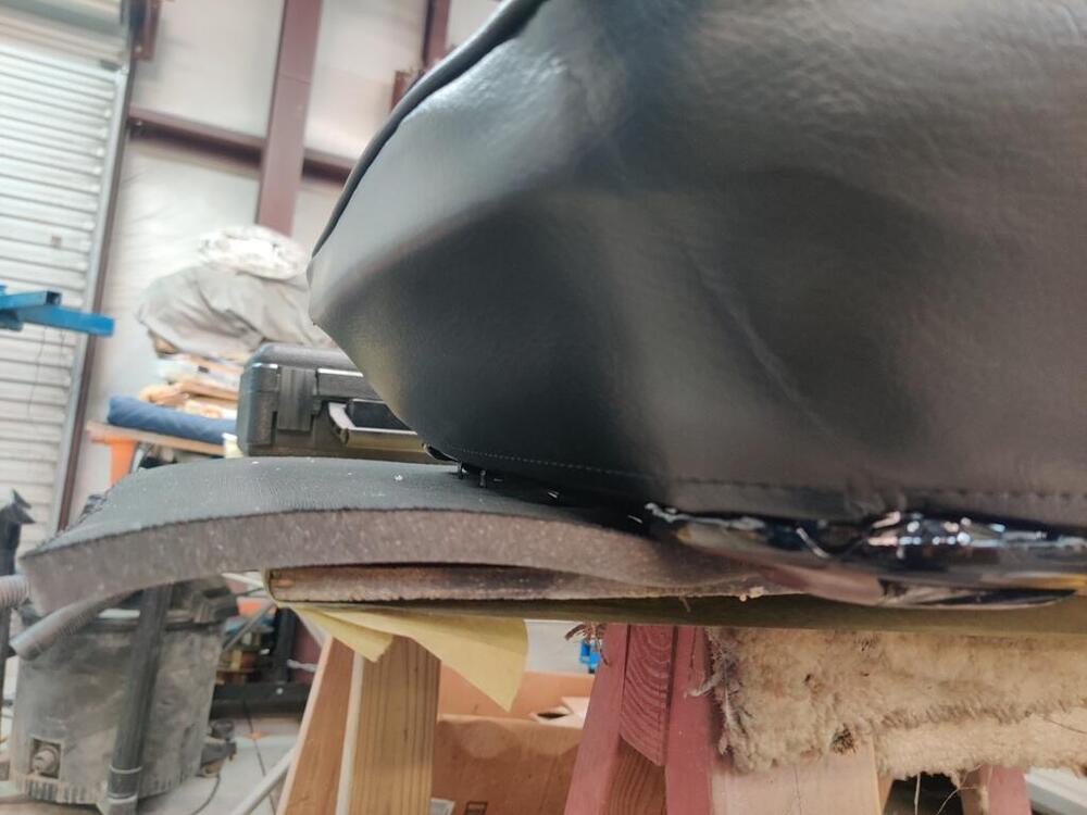
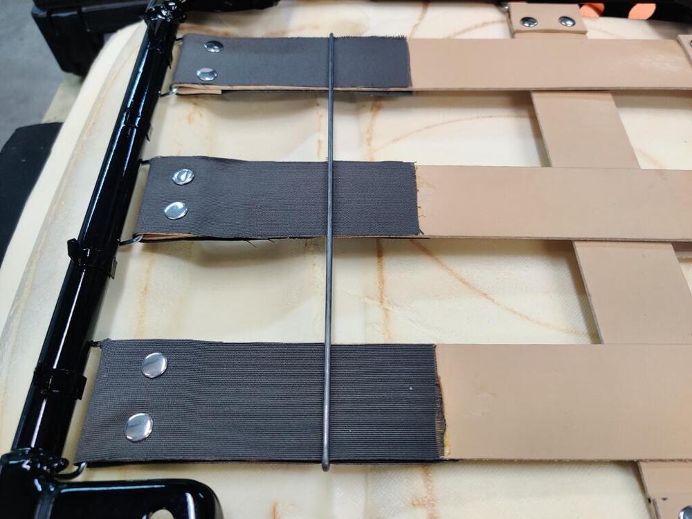
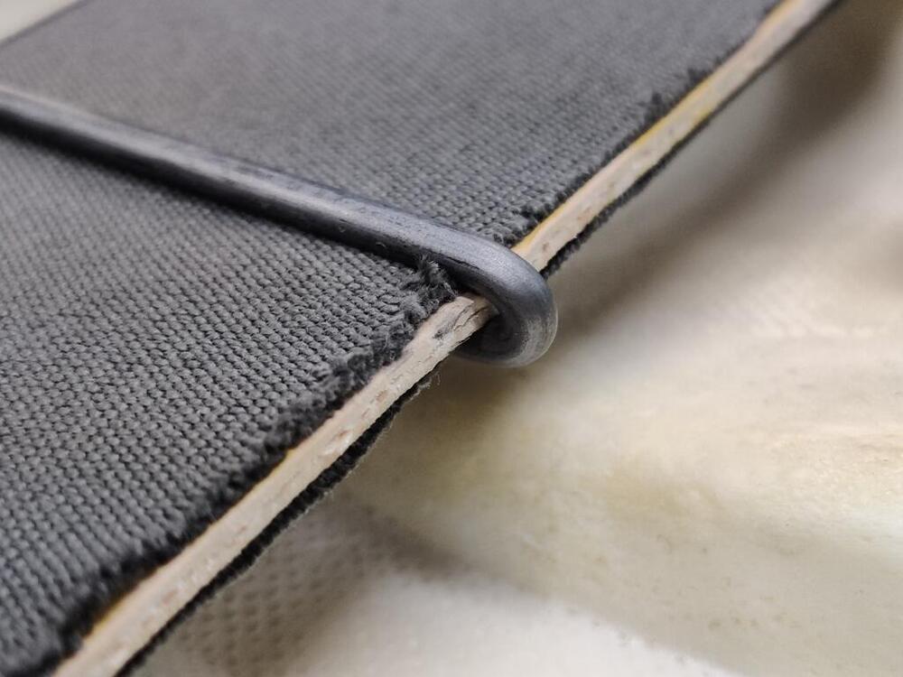
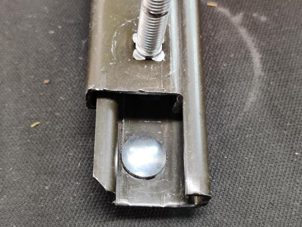
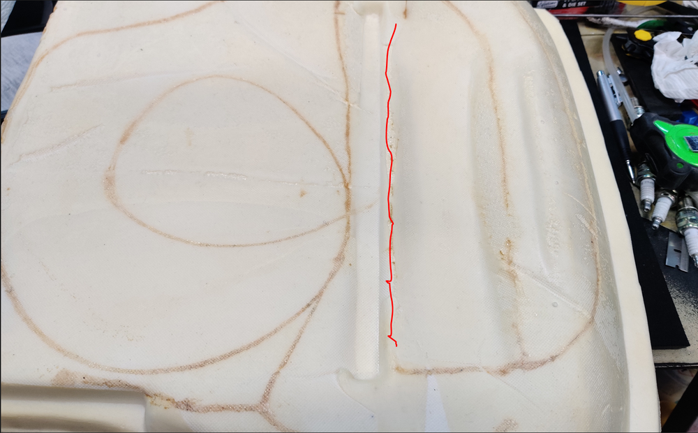
For some reason, the valve spring retainer tool didn't get here on time. It will be next week before I can pull the retainers from the exhaust valves. So, I switched back to the seats today. I spent a couple of hours doing research because I don't see how I need to proceed. The first issue I have is I don't know how to attach the flap to (or through) the seat foam. My seats do not have springs - they have Pirelli straps. The replacement foam has a slot in it. This slot is not cut all the way through the bottom of the cushion. I measured the depth of the slot at 2 nd 3/4" inches. Looking at the underside of the cushion, the bottom of the slot is offset to the right of the impression (long, skinny rectangle) you see here. I drew a red line approximately where the bottom of the slot is in this picture. There is a thickness of about a quarter of an inch of foam at the bottom of the slot. But, the seat upholstery flap that goes down into the slot is only about 2 inches deep. As I understand it, there should be a wire that is inserted in this flap and hog rings should be used to attach this wire... to something. I just don't know what. This picture of @kats seat appears to have a wire running under the Pirelli straps. I have attempted to replicate that, bending hooks in the wire to locate it around the straps, however, I just don't know how to proceed from here. I am thinking about making a matching wire and putting it in the fabric flap on the seat upholstery and then using hog rings to pull the two wires together. But, I am concerned about the difference in measurements (2" depth of the flap vs. 2.75" depth in the slot). That may be ok though, as clearly, there has to be some tension on this flap to pull it down for the proper appearance. Perhaps when the wire placed inside the flap is hog ringed to the wire that runs under the Pirelli straps and is pulled down about the three quarters of an inch, the "compression" of the seat foam will be about right? I set that aside for now and worked on cleaning up the seat tracks. They were gummed and I could hardly get them to move. I used copious amounts of WD40, as brass wire brush, compressed air, and paper towels. To assist with cleaning, I moved the tracks back and forth repeatedly. For the track that has the handle, I disengaged the spring so that the track could move without latching. Bending tab at the end allows the spring to move away so the tang can be slipped out of position. This allows the handle to free float. Then, the track can be moved back and forth without the handle engaging the slots I am going to think about how to best proceed. If anyone has any guidance, let me know.


-
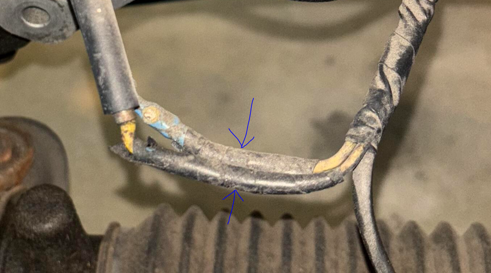
Because both of the wires coming out of that alternator case are yellow... with no other color stripes, they do not look factory to me. Neither do the connectors which appear to have been spliced into the wires on the harness. I suspect some wiring modifications were made.
-
"This 240Z is now offered on dealer consignment in Oregon". Some sellers hire BAT specialists. I believe 911R is just a specialist who does the photography and perhaps handles working with the person from BAT assigned to the car.
-
So... if the market is soft, it is a very interesting time for the "Franklin Mint" car to come back to BAT: https://bringatrailer.com/listing/1970-datsun-240z-128/
-
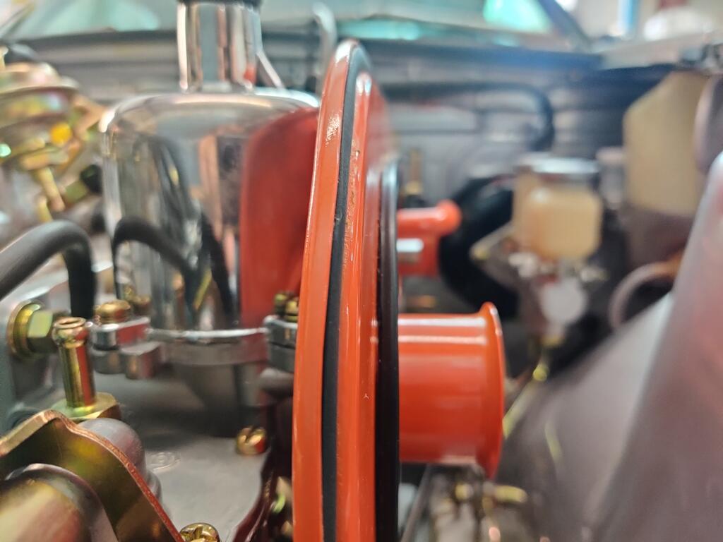
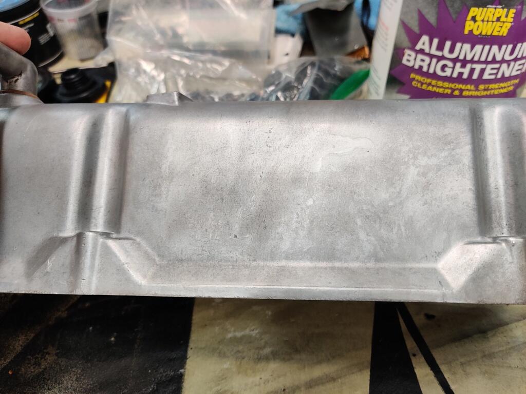
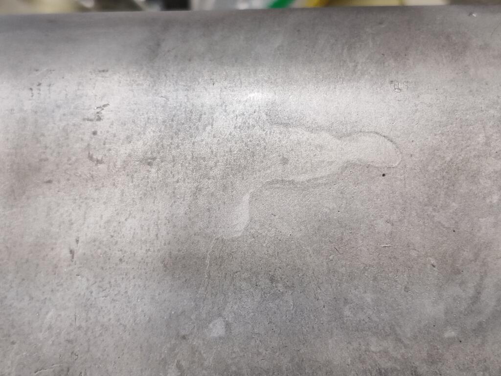
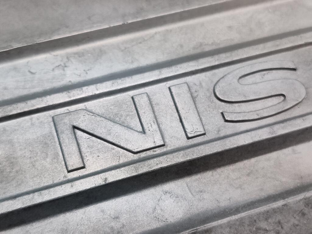
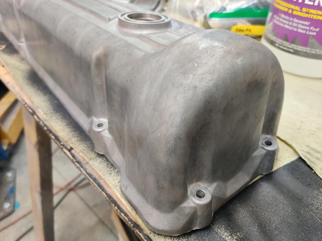
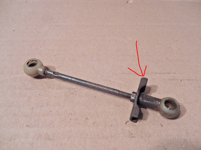
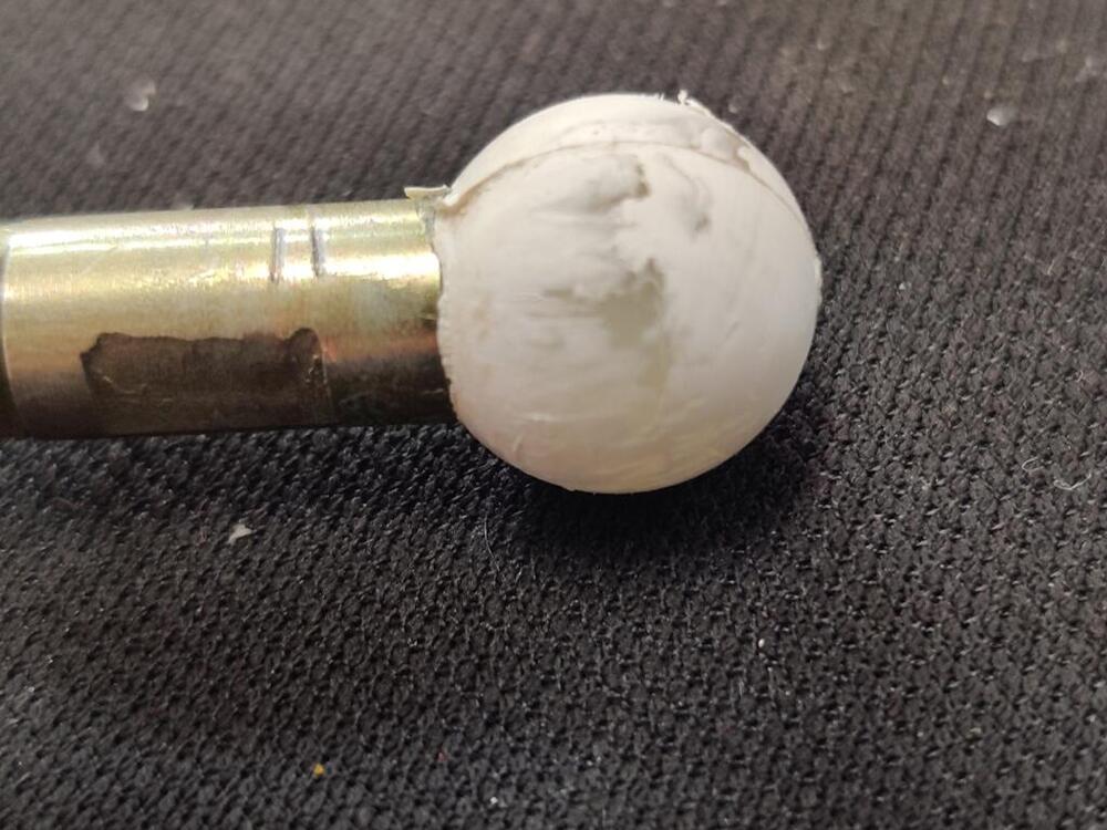
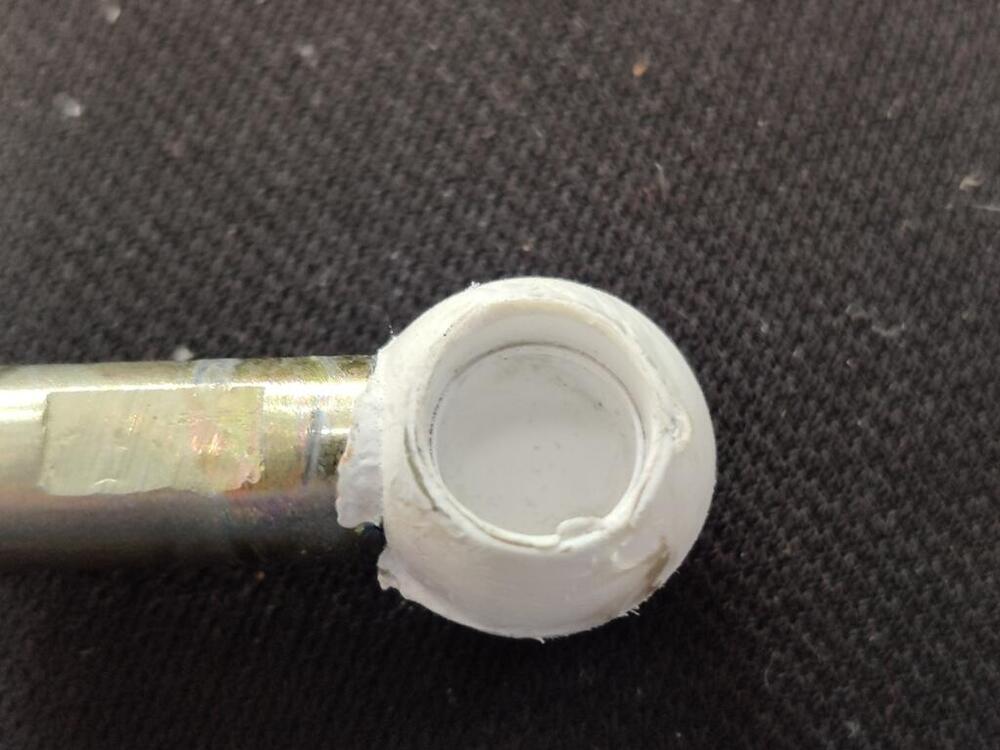
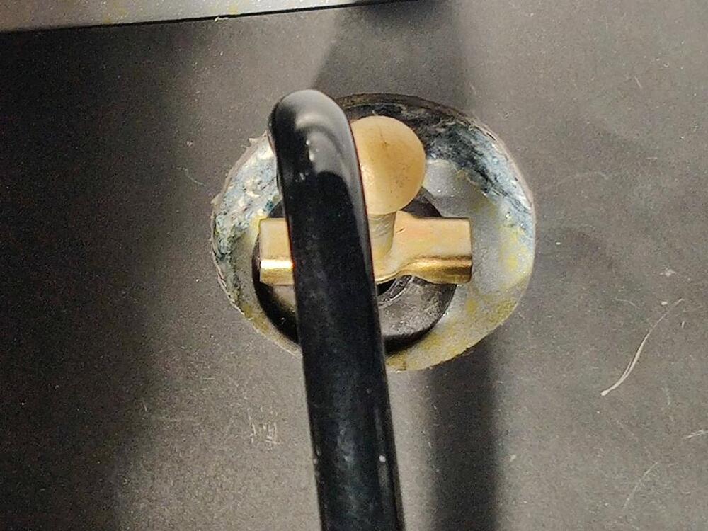
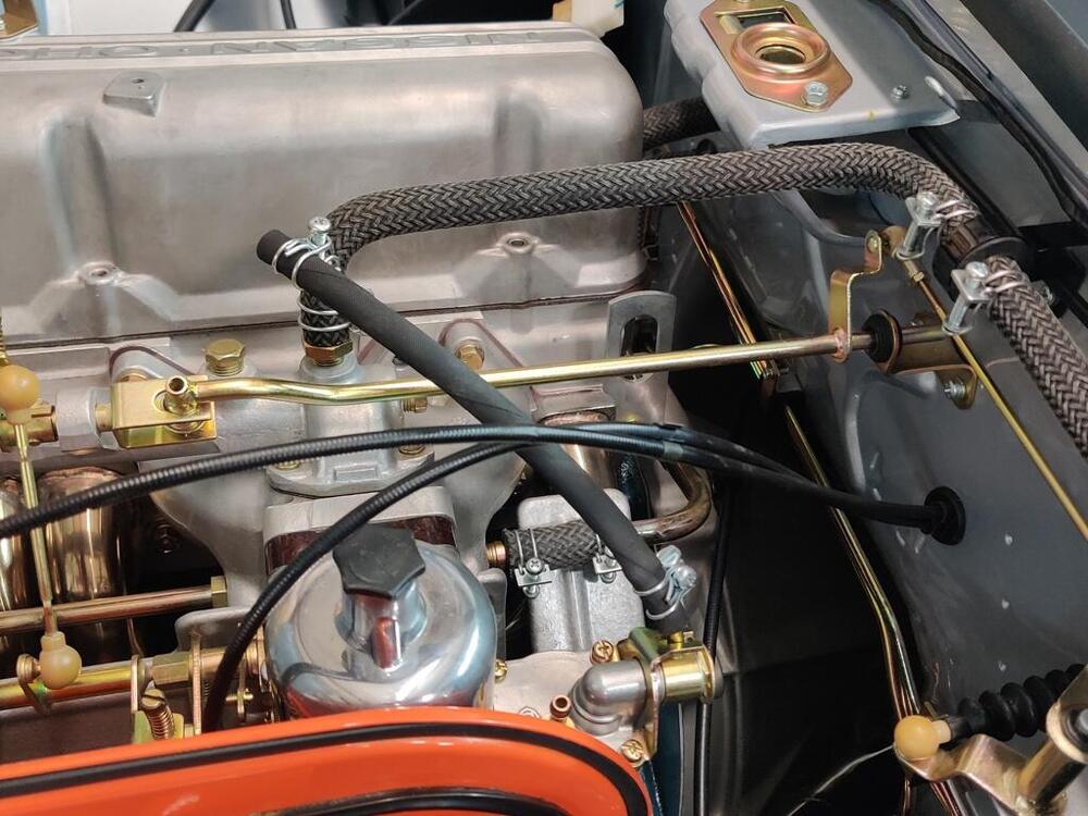
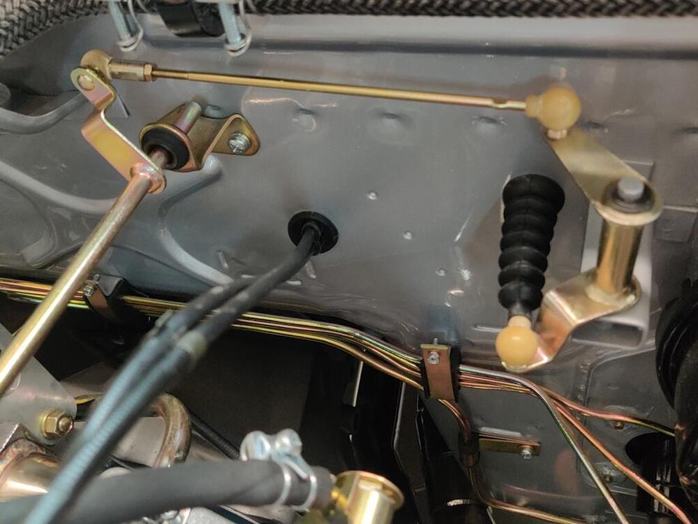
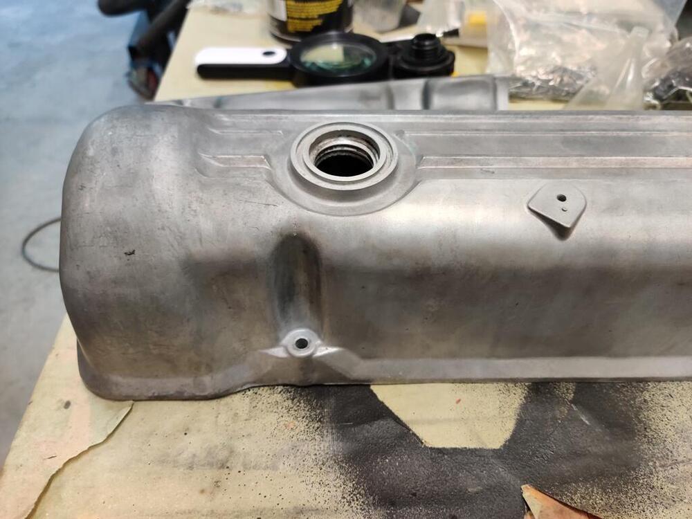
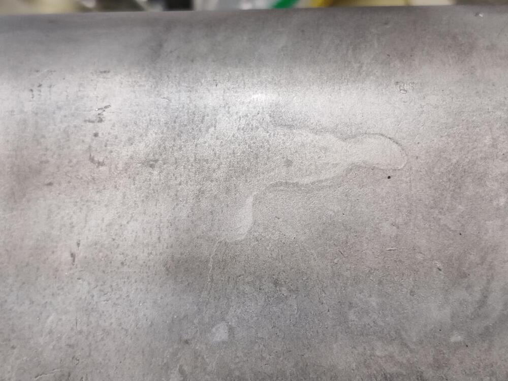
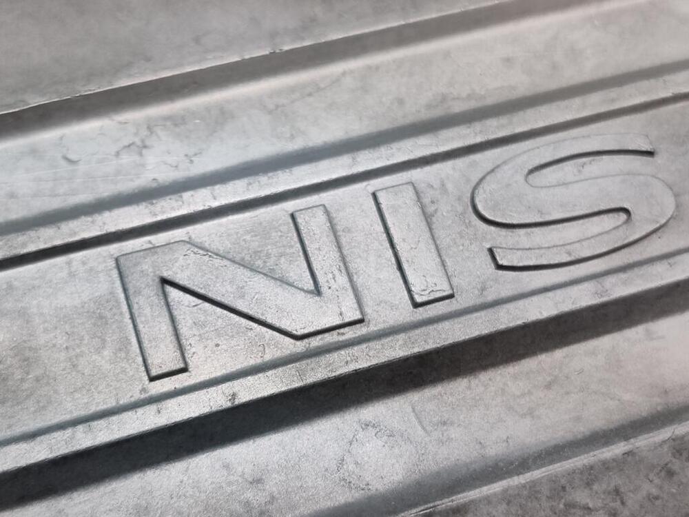
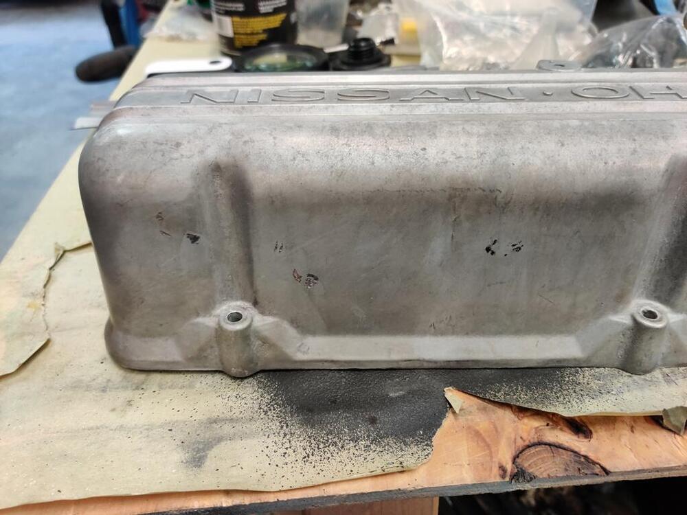
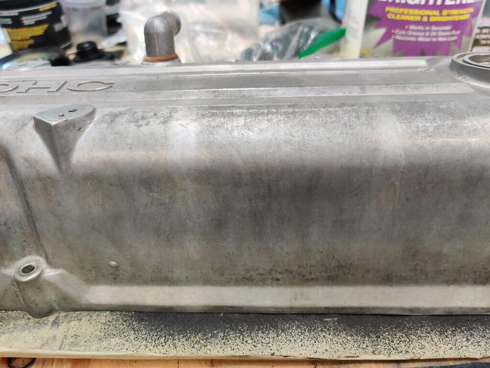
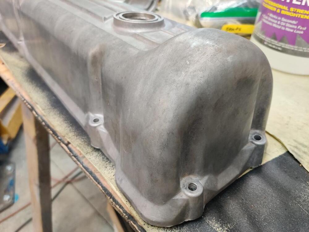
I attempted to remove the valve spring retainers from my exhaust valves this weekend with the homemade valve spring compressor tool I have use successfully before. However, this time, it didn't work as well as I recall it did last time. After futzing with it for a couple of hours and only getting one retainer off, I gave up and ordered one from Zcardepot.com. My homemade one interferes with the came towers and extracting the collets out is a real pain. Hopefully the new one will be a lot easier to use. In the meantime, I am working on what there is left. One of those things was installing and adjusting the throttle linkage arms. While I am familiar with this part (see red arrow), I never knew what its purpose was - do you know? Well, I may have figured it out. I think it is a linkage "stop". As I was assembling the linkage, it seemed logical to me that the little wings on this part may have been intended to contact the back of the rubber bellows that attached to the firewall. As I worked to set the lengths of the rod (this short one and a longer one have one threaded ball socket end) the location of this piece fell naturally to a position that eliminated all of the "slop" in the linkage after the throttle plates in the carburetors had just contacted their screw stops. In other words, you can then set the depth of this "winged" piece to contact the back surface of the bellows just at the point where the throttle plates in the carburetors have closed. Doing this, you will prevent introducing slop in the linkage which occurs after the throttle plates are shut but you continue to release the gas pedal as far as the pedal return spring will pull it from the floor. After setting the winged piece, I confirmed that even the slightest movement at the pedal caused carburetor shaft (and thus, throttle plate) movement. When releasing the gas pedal I now have a muted "thud" as this piece hits the back of the rubber bellows... and allows no more movement in the linkage beyond the throttle plates in the carburetors' seating. Kind of cool! It will be interesting to see how that all feels when driving the car. While I was doing all this, I ensured that I got full throttle opening at (both) carburetors by pressing only on the gas pedal inside the car. I am never all that surprised when I check and find that pressing the pedal to the floor does not fully open the throttle at the engine! The plastic ball sockets on the linkage turned white during the plating process. To address, I used a propane torch and very carefully heated them. The heat causes some type of reaction which restores the color of the ball socket. But, you have to get it hot enough that melting starts to occur. After heating, I went over them with some fine grits of sand paper to restore areas that has melted a tad. White socket... and my throttle linkage stopper in action (though I think I need to flip it around 180 degrees): Throttle linkage detail: I have read about getting dinged at Zcon for valve covers which have been glass bead blasted. I also know that there is quite a bit of variance in finish with glass bead blasting. You can use different media, different pressures, and even do vapor blasting which uses media along with water. For my valve cover, I tried cleaning it really well with #0000 steel wool and degreaser. And then I tried some Aluminum Brightener. After those efforts, I still had darkish areas that looked like stains on my valve cover: So, I started experimenting with glass beads set at very low pressure. The glass beads I was using have seen may work cycles and I was using only 20 psi. However, I was getting pretty good results. In this first pic for example, I concentrated efforts on the area at the top of the valve cover between the oil cap hole and the casting bump (for the spark plug wire holder). In the second picture I was concentrating in the area between the two bolts. In the third picture you can see the area of transition (darker, not blasted area on the right). In this first picture below, I had hit the N and and the I in Nissan and some of the area above and below the N. The downside is that it takes a lot of time at 20 psi. But, it did make a big difference in lightening the valve cover. I got a little more aggressive in a few areas with 25 psi, but I think that started to look unnatural. Anyway, I was pleased with the overall result. A note, if you do this, you have to seal the vapor compartment in the valve cover, or remove that plate inside the valve cover like I did so that you don't leave glass beads in there.

-
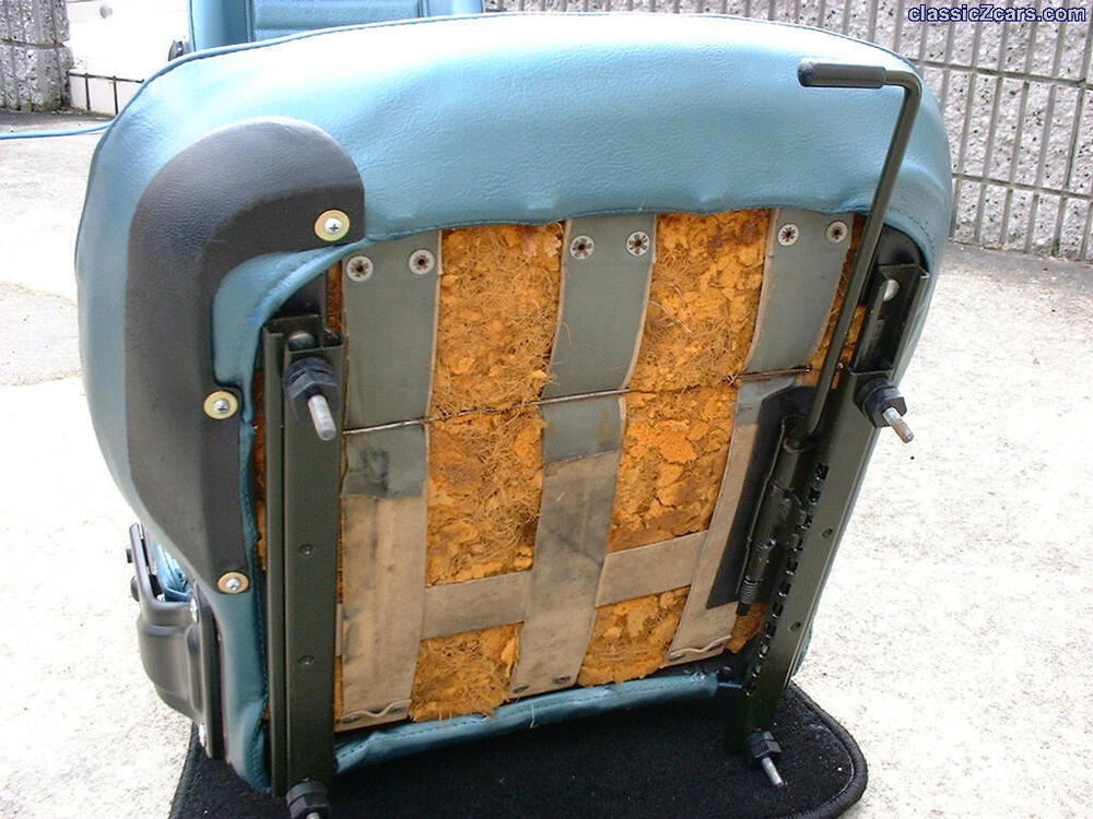
I have seen some cars with original backs in very good condition, but the bottoms not. And I have seen some where the bottoms have been replaced but not the backs, like this one on Bringatrailer a while back. https://bringatrailer.com/listing/1970-datsun-240z-101/ For the right person, they will be valuable. But, quality aftermarket ones from Distinctive Industries exist also for about $600 (in black). If they are the early type (can you take a pic of them outside the bag?) I'd put their value around $600 - figuring if I had good original backs (rare), I'd be will to spend that much to try to keep the seats original.
-