rossiz
-
Posts
1,109 -
Joined
-
Last visited
-
Days Won
30
Content Type
Profiles
Knowledge Base
Zcar Wiki
Forums
Gallery
Events
Downloads
Store
Blogs
Collections
Classifieds
Everything posted by rossiz
-
i agree that measurements would be a very interesting exercise - but the trick is measuring movement relative to what? in other words, are the tops of the rear strut towers are moving in relation to each other, or in relation to the base where they attach to the subfloor pan, or in relation to the side walls of the car. all these movements are possible and would depend on the relative stiffness of the components and how they work together. i also agree that the body feels like it's twisting when, for example, you approach a driveway apron or when going over a speed bump slowly on just one side and this does seem to make the most interior panel noise. if the rear strut tower, when receiving load through the strut, leans in to the center of the car by flexing the subfloor it's attached to, then a diagonally braced connection between the two towers would make sense. reading john coffey's post brings up a different perspective though - for serious performance on a track, the stiffness of the whole chassis as a unit would be more important than trying to eliminate squeaks and rattles... i can see how connecting all 4 strut towers would do the most, although it's not a very practical approach for a street car. i've thought about the frame rails - they are definitely a little flimsy. mine are completely rust-free, and wen i put one end of the car up on stands they flex enough to change the door gaps. but that's an order of magnitude of work beyond a simple bolt-in brace. the fact that datsun chose to diagonally brace the towers in a lateral fashion and shape the towers with their weak axis in the fore-aft direction suggests that these forces were considered less important. not that they got it right though... a really simple test might be to simply stretch a thin wire between the tops of the rear strut towers and watch how much it sags under basic maneuvers like the driveway approach or one-sided speed bump. this might at least tell us if the car is twisting diagonally (across all 4 strut towers) or if the rear towers are acting independently.
-
while i've never tracked my 280 and am certainly not qualified in any way to evaluate body/frame flex and handling (no sports car experience other than this one) the symptom that brought the issue to my attention is how much the interior of the car squeaks and creaks over bumps and when thrown into turns. this leads me to believe that the car is flexing enough to cause the interior plastics to twist and rack. the sound is definitely coming from the rear of my passenger compartment, and since i've upgraded my sway bars, replaced struts & springs and cleaned/lubed all of the suspension except for the rear control arm spindle pins, i don't believe what i'm hearing is related to suspension components. my first reaction to the factory installed diagonal sheet metal bracing on the sides of the rear towers is that it appears to be too steep an angle and it braces into the sheet metal subfloor deck, which appears to be a pretty flexible component. that's why a simple pair of diagonals making an "X" seems to make sense to me on a gut level. i don't know how the towers would flex in any other direction than laterally, as it would seem that since the struts are angled to the center of the car, the towers would want to lean towards the center of the car when suspension load is placed on them. this would be solved with a lateral brace between the left and right towers. the control arm design is triangulated to resist front-to-rear loads, and even if there were front-to-rear flex in the control arms, they are only connected to the tower through the strut, which has ball pivots at both ends so the only forces going to the tower would be in line with the strut.
-
looks really nice - i've been thinking about a similar brace that was a pair of diagonals, or a horizontal "X" which would put a lower point in the center. this would make it easier to access/use the storage space between the brace and back of the seats (which is a perfect place for a couple bags of groceries). not to hijack, but maybe a broader design discussion? any thoughts on this?
-
those are beautiful - i can't tell from the photo if they are raw wood or have a finish... if not, what kind of finish will you put on them?
-
good vibes from seattle - can't wait so see the first startup video! btw, what kind of fuel pressure gauge is that? i'm about to replace my 4th one, as they get chewed up from the injector pulses. the little brass gears inside just wear themselves out in a few months of daily driving. i've been using the cheapo hardware store variety, but will be switching to something with a sensor and remote gauge to solve this...
-
very little progress today - family obligations overruled... got the radiator and fan back in and a few misc. fasteners. hoping for a dry afternoon tomorrow...
-
holy crapoli - what a perfectly simple idea! i'm gonna make a home-brew "non-clicking" tensioner setup for the F54/P79 so i never have this issue again.
-
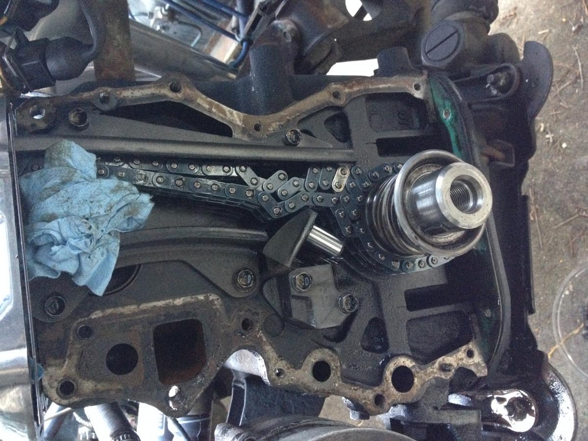
made some progress today - and a huge thanks goes out to my wife for helping me push the car out of my yard and into the neighboring concrete driveway (vacant house in foreclosure whose driveway i've been known to occupy from time to time) where i could get it up on stands. the woman is a saint and i don't know why she puts up with me - must be my cooking... anyway, got the following done: front cover off, straightened out the jacked up spring on the tensioner & re-installed, lined up the dots/bright links to time the cam, front cover & harmonic balancer back on, re-installed the head (again). it got dark and cold, so i called it quits for the night. tomorrow i will re-install the oil pump and dizzy, radiator & fan, alternator, exhaust & intake manifolds, re-fill the cooling system and if there's time i'll do a cold lash adjustment and a final top end lube. then maybe she'll fire up, eh? the chain tensioner did the nasty - again

-
yes, last time the cam tensioner had fallen all the way out of it's cylinder and was sideways when i got the chain on, and when i turned started her up the nose of the tensioner sheared off the shaft and the parts fell into the bottom of the timing cover. i believe the only reason this was able to occur is because the timing chain was worn enough to have slack that would allow the tensioner to be where it was and still get the cam gear on. i have a new chain now so there's no extra slack and the cam gear isn't even close to getting on without the tensioner in place. i'm getting myself geared up to attack the second half of this job - last night was totally deflating...
-
i've heard that it is in relation to the catfish - not the feline cat. this fish (i've read) has a thick, rubbery skin that is difficult to remove, and every fisherman had his own process for "skinning a cat".
-
the turbo head bolts are for the F54/P79 i'm building - this motor has new NA head bolts, which i've been torquing to 62 i brought all my tools out to the car, set up the towel over the fender and brought out my newly set-up head with hopes of hearing her fire up before dinner maybe even drive her to work tomorrow - but it was not to be. instead, today was another day of green-eyed Lilith testing my resolve... i got the head installed, torqued up and then went to put the cam sprocket on, only to hear one of the most miserable sounds - that little "click" from inside the timing cover when the chain tensioner pops. yup, that one little click turned a 2hr. job into a two day job. the good news is this happened the first time i replaced the head, so i shouldn't have to deal with rusted, broken bolts. the bad news is the car is parked in the dirt and i can't jack it up, so i'm crawling around on my back in the filth to get at all the stuff that needs removing from underneath. damn, this car is lower to the ground than i thought. tomorrow i might have to get some wood under it and put it up on ramps to get better access. tonight i pulled off the splash pan, drained the coolant, pulled off the hoses and fan, removed the radiator, pulled the distributor, alternator tensioner brace, then when i went to remove the crank pulley i realized that since the valve train wasn't connected to the bottom end, i had to take the head back off or risk bending valves. head back off, crank pulley bolt removed, loosened about half of the front cover bolts and called it quits for the night since it was pitch black out and getting cold. tomorrow i'll have to pull the front sway bar so i can drop the oil pump and pull the dizzy drive shaft, then hope like hell i can get the timing cover off without further mishap. any good vibes would be greatly appreciated...
-
It will make sense when it comes time to install- the longer ones go through the cam tower base.
-
just tried it - works perfectly, and soooo much nicer than tapatalk! thanks for fixing
-
don't beat yourself up w/having reversed the springs - i did it when i went to a set of eibach progressives and found that this is a fairly common mistake. it sure would be nice if they were labeled for those of us who don't know... also, i found that when i re-did my suspension it took a little bit of driving for it to settle in to the correct ride heights - probably because the bushings/sway bar/etc. were tightened when the car was up on stands and things needed to find their center under load. you may find the same applies in your case. just out of curiosity - did you grease up all your bushings prior to assembly?
-
well, i don't know if it's the "nail" or not... i was worried that the valve job was done poorly or that the valves were dressed improperly, which in my opinion would have been worse, but the issue was one of somebody grabbing the wrong cam, assuming it was a stock grind and slapping it together without checking the geometry. still a big QC issue, but a more understandable mistake i suppose. fwiw - i've been in touch with them during this whole fiasco and he's been very open to hear about it and wants to know my findings so he can discuss w/his machine shop. i'm sure he has a shop that does all his heads so hopefully the feedback will assist in keeping this from happening to others...
-
fwiw - i got the rear bumper from futofab and the front from black dragon. both are beautiful, and very affordable.
-
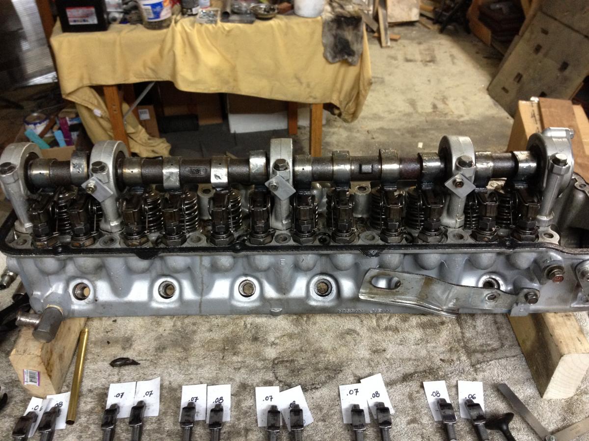
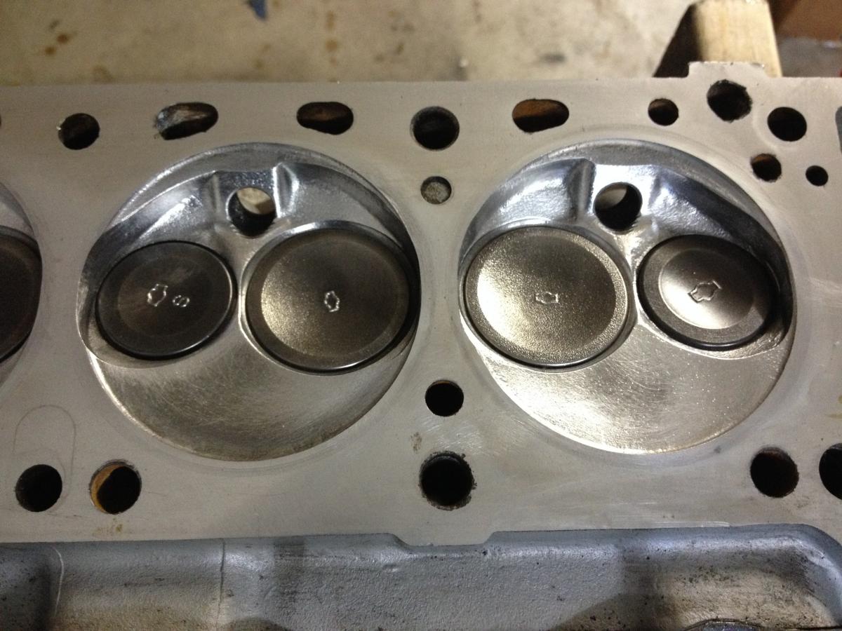
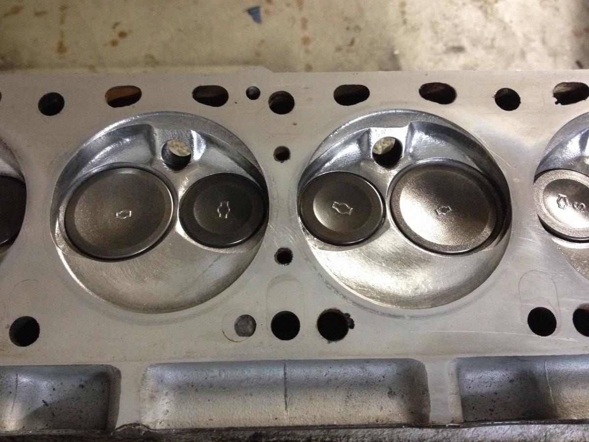
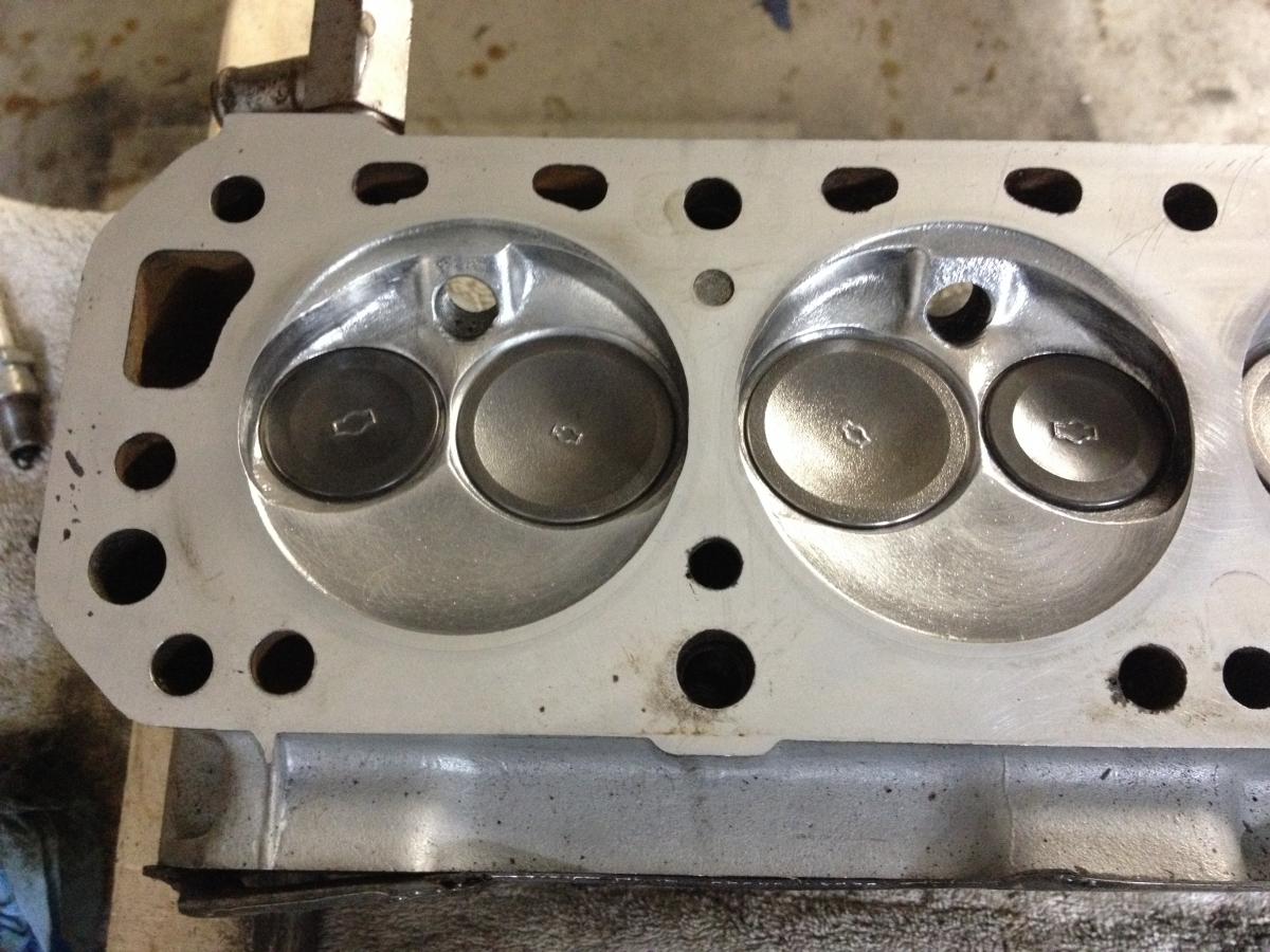
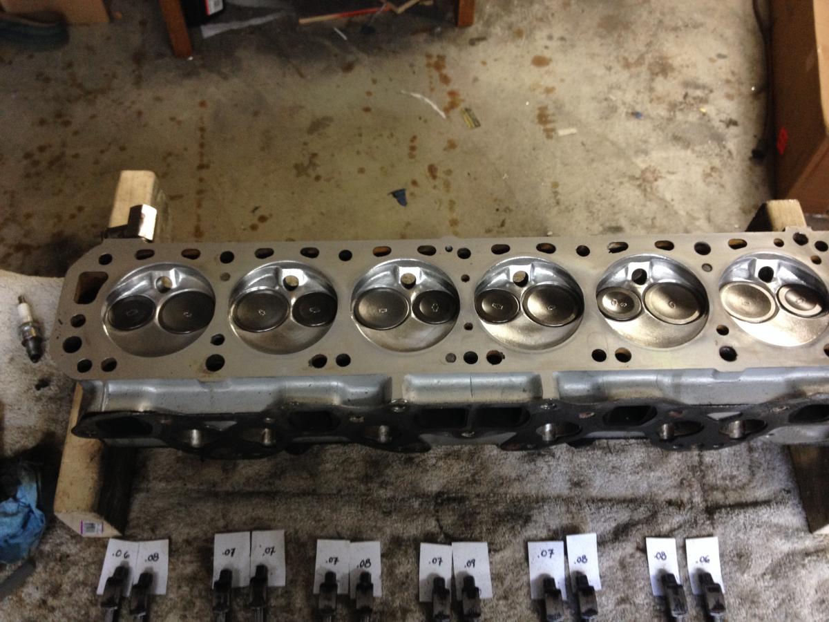
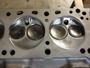
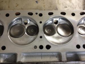
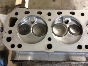
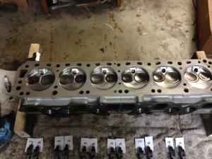
started getting a little depressed at the prospect of spending another bunch of cash on lash pads + aftermarket spring keepers, especially since i'm re-building another motor for this car... took a moment to think about it and realized the one thing i hadn't measured was the cam... turns out it was the problem - it's a re-grind with higher lift and smaller base circle, and they dropped it into a stock cam setup. i measured every lobe and compared them to the cam in my original N47 head (the one that came with the car) and put all the data in a spreadsheet to figure out how they related to each other. then, just for kicks, i pulled the cam, rockers and lash pads from the original head and put them in the new one and see how the geometry worked. i kept all the assemblies together (lash pad & rocker w/same cam lobe) and marked the rockers with sharpie to check the wipe patterns. the result: perfect! every rocker wipe pattern lined up exactly as it was on the original head, right in the middle, as set up by the factory in 1978. so i went with it - cleaned everything up, slathered it in the "z paste" that came w/the re-surfaced rockers from delta cams and did a quick polish on the combustion chambers. the N47 cam is internally oiled and the N42 is set up for a spray bar, and i didn't want to mess with doing both and wondering if i had enough oil pressure, so i decided to block off the spray bar outlets with some small aluminum plates and just rely on the internal oiling. i'm hoping to get some time tomorrow afternoon to put humpty back together and see if it all works... the measurements Cam Measurement Comparison.pdf spray bar block-off plates chambers all cleaned up

-
true... but lets be honest - we never really want the project to be "done", do we? i mean, if we wanted a car that was "done" we'd just buy something new and forget about it. the fun is always having a little something to fiddle with...
-
yucko - no fun... get some rest and get better!
-
the little details make all the difference!
-
so if stock valve retainers are only deep enough for lash pads less than .170, any recommendations on an aftermarket set to hold thicker ones?
-
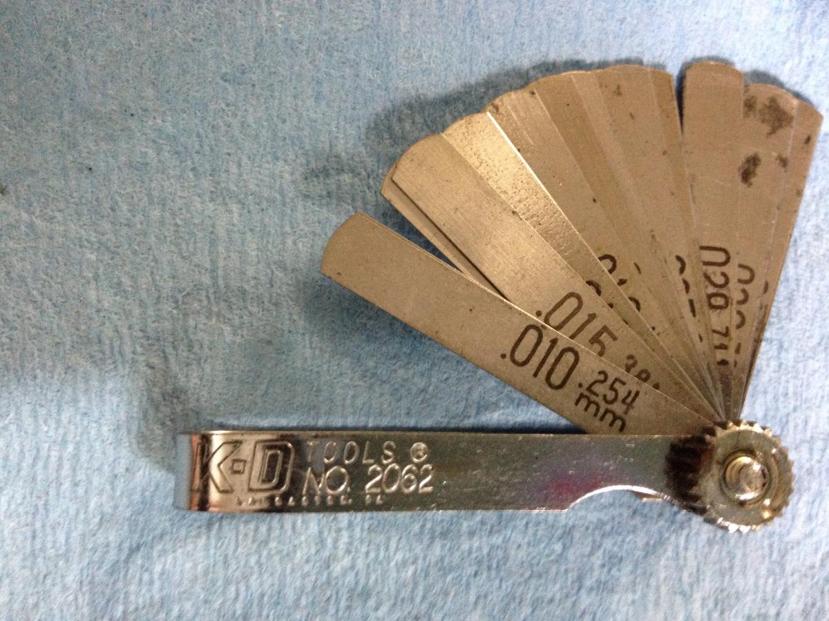
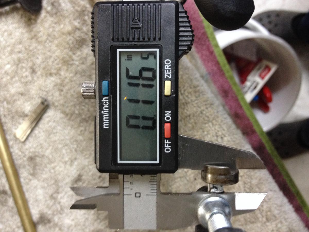
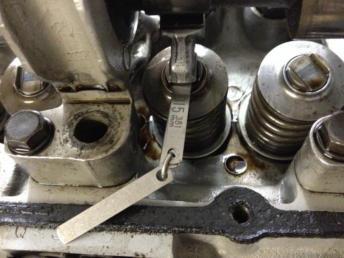
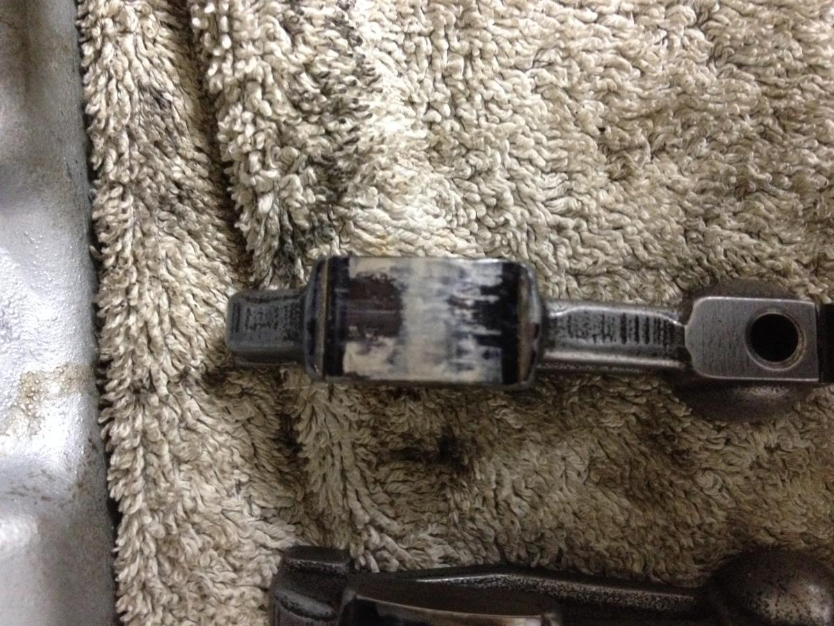
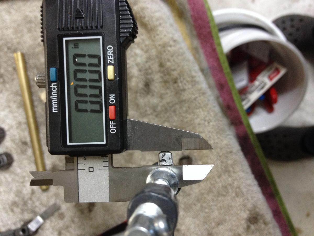
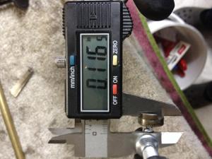
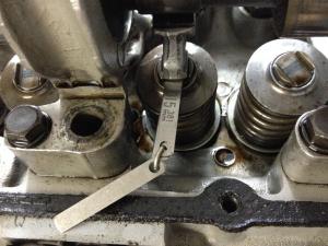
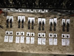
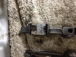
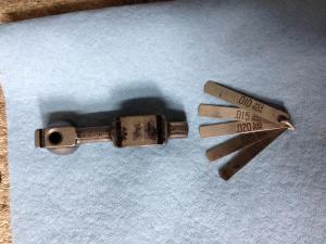
finally got all the measurements done - learned quite a bit. first off, i was surprised to find that the measurements were all over the place. second, this is a job that takes time and patience, as every .010 makes a visible difference on the wipe pattern. i was lucky to have a tiny set of feeler gauges, they've been in my tool set for ages, so i don't know if they're still available but they're practically made for this job - they are just the right width to fit in slot at the top of the lash pad and short enough to avoid hitting the perimeter of the head. i pulled out the following shims: .010, .015, .020, .025, .030 to mix/match as required - this gave me combinations to make increments of .010 all the way up to .1 so i could hit standard size lash pads. i used a piece of solder wire to make a loop to hold them together so i wouldn't lose them - the solder wire is soft, easy to open and close as i had to pull/add shims to set each rocker. the process: black sharpie on the rocker wipe surface, add shims, set correct lash gap, spin the cam, pull the rocker, check the pattern & repeat 'till the wipe pattern is centered, then move on to the next one. it is a quiet, methodical, satisfying project - not difficult or complicated, and it feels good to get the pattern right where it belongs. after i had the amount of shim that needed to be added to each lash pad, i figured i should check the lash pads to be sure they were all the same. made a little fixture for my digital caliper to allow me to reach up into the recess in the bottom of the lash pads and zeroed it out, then measured all 12. i measured flat across the top of the wear surface, to avoid mis-readings from the wear divot made by the rocker arm tip - this is consistent with the flat surface generated by the feeler gauge shim stack i used for measuring as well. turns out the lash pads were not all the same - they ranged from .117 to .121 and although the difference was fairly small, it matters when added to the shim measurements i had. adding the measured lash pad thickness to the shim stack needed to center the pattern and rounding to the nearest .010 gave me the final size of the lash pads i would need. turns out i need 2 pads at .18, 5 pads at .19 and 5 pads at .20 for this head setup. so this head was set up way off - i can only guess that the valve seats were set high or not ground deep enough, or both. MSA has the pad sizes i need, but they have a little warning that states: "Application Note: Aftermarket spring retainers are required for any lash pads over .160" thickness." why is this, and what is the issue with going with what i've got? i don't really want to spend even more on this head if i can avoid it... the perfect tool pattern set measuring lash pads measurements complete


-
cool! love those wheels...
-
good to see more happening - i'm watching & learning... and thanks for the tip on head bolts, i picked up a set of turbo bolts from courtesy nissan for $60 as well - a $40 savings over the last set i bought from dpllc, and those were the NA bolts...
-
are you notching for clearance due to high-lift cam, or just to de-shroud for flow?