


HuD 91gt
Free Member
-
Joined
-
Last visited
Everything posted by HuD 91gt
-
70mm m10 x 1.5 rings a bell but double check. Also depends on what transmission you have. 5spds require the longer bolts (70), where as 4 sp you have shorter ones.
-
I'm sticking with linkage issues. Take pictures of it and someone will at least be able to take that out of the equation. Others have requested videos. Your not gojng to solve the problem by just guessing and changing out all the parts. You need to diagnose it and eliminate issues. It will get very expensive the way you are doing thjngs.
-
haha. Love the rooftop view the most.
-
Looks great, and moving at a much faster pace then my apartment project... Although slightly more hermetically sealed... or atleast i'd hope it is.
-
-
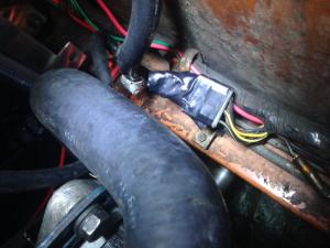
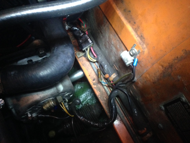
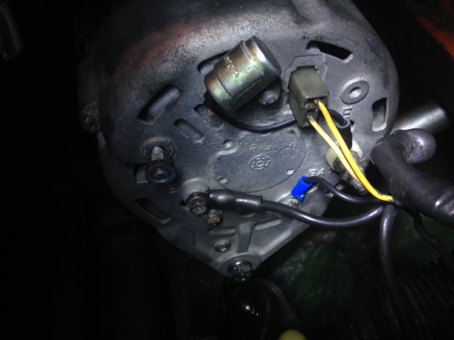
I just got back home from the garage, and after running a small ground straight from a bolt on the alternator to the body I've think all my resistance readings were a bit off. My voltmeter was acting funny, I have a feeling the battery is probably close to dead. I'll get a new battery and check it over when I get back from work on Monday. It's too bad, I would have liked to have driven the Z, I get satisfaction driving it to work the odd day. After running the ground, I started the car and there was no change. There is also a capacitor (or resistor) that was mounted to the old VR which was somehow wired into the old harness. I left it there when I did the install (pictured). When the car was running, I disconnected the capacitor and immediately the voltmeter show a much more "normal" charge of 10-15amps, but the needle still flickered quite a bit. I didn't rev the engine too much as it's getting late and the car is in a residential neighbourhood. Does anyone know what this capacitor did on the old setup? Do I need it now? The write-ups I see don't mention it at all. So, in the photo below, (sorry I couldn't find an app on my mac to highlight the areas on the photo) the VR connector is taped up. I used spade connectors, and followed the diagram from the link posted. I then used electrical tape to make it weatherproof. The capacitor is also in this photo, and it is more central, screwed into where the VR use to be mounted. When this was disconnected from the system, the reading was much more "realistic", but the needle was still erratic. The photo below is just a photo of the VR connector taped up. Not really anything to see here. This is the back of the alternator. I ran a ground (blue ring terminal) from a random bolt on the back.

 The T, has a a high resistance on the vertical portion. The top of the T, I get no reading at all. The top of the T also shows battery voltage when the connection is in place.
Also to note, the alternator that was on the car looked identical to the 1975 you posted, but the external regulator was still being used.. Is this correct?
http://www.classiczcars.com/topic/46888-240z-alternator-upgrade-instructions-w-pictures/ I used the diagram in this thread as it seems to be one of the few which talk about the 240z directly. I do have a "P", so it should be regulated. I'll head out shortly and test the voltage as well at the top of the T. I also just noticed I may have done something incorrectly in regards to that diagram. I left connections 3 + 4 on the left diagram (To regulator), not connected. This is correct, no? In fact, I never used the regulator side connector at all. I just used 4 spade connecters and put them directly into the female side of the connector (alternator side) and taped it all up. Leaving the connections which would be 3 + 4 empty.
Yes, I did the diode trick, and bridged the two sets of wires (one with the diode) and removed the external regulator. I wonder if this alternator isn't internally regulated at all. I'll have to measure the resistance at T as Captain Obvious stated. I'll try some more grounds as well.
Finally got around to mounting the alternator up. The car runs fine, although it seems the ammeter (or voltmeter?) is bouncing all over the place. It seems to sit in the middle on idle, and when revved up I see a charge of 20-25amps, it also bounces around quite a bit. The old alternator was very stable, and didn't bounce at all, it charged from 0-10amps. One thing that may be causing this is the wire connected to the "E" on the alternator is loose. The bolt seems to be slightly stripped and I can't tighten it down. If it is a ground, could I ground it somewhere else on the alternator?
Take a very close look at the linkage, and look very closely at diagrams and other photos of linkages online. It's possible he got mixed up when putting the carbs back on. It's a long shot, but you never know. I had mine installed wrong at first.
The bumpy road thing makes me believe it's a motor mount messing with your throttle linkage. Go over your throttle linkage very well, insure everything is lubed, and free of any stiction. This started happening after your ztherapy install as well? If you get a change in idle speed you may probably have a small leak in the booster. For future testing and troubleshooting keep it blocked off. Did you drive it at all with the booster blocked?
An easy way to block the brake booster, is to reverse the check valve on the firewall which is in the middle of the vacuum hose from the balance tube to the booster. It only flows one way (if working properly). I've done this before and and if my memory serves me correctly it works great. You could also disconnect the hose at the check valve and shove a appropriate sized blocking device, and use a hose clamp. Your over thinking your issues. Think methodically, figure out what your actually trying to accomplish and go from there.
An easy way to block the brake booster, is to reverse the check valve on the firewall which is in the middle of the vacuum hose from the balance tube to the booster. It only flows one way (if working properly). I've done this before and works great. You could also disconnect the hose at the check valve and shove a appropriate sized blocking device, and use a hose clamp. Your over thinking your issues. Think methodically, figure out what your actually trying to accomplish and go from there.
Great to see the finished product!
Since I put the SM needles in, I think I'm going to give blue method a go. Picking up a used wideband next week! I was going to switch back to stock needles, but the new motor is going in, in about a month anyhow so I might as wel keep them for the time being.
I saw the same buildup in my manifold. Was curious as well.
I see what you mean. Hope it doesn't affect performance too much.
I have no tools nor experience to change the rings. I would be going straight to the books. The N47 head is on the F54 block already. It has the stud holes for the SU intake manifold. They will mount right up. No infection holes to fill as those are in the injected manifold which I'm not using. The only thing I need is to run an electric fuel pump as it has no cutout for the mechanical pump. As we sit, I'm leaning towards just swapping it in. Thanks for the help, I will keep everyone updated on how it goes.
Oh it's possible to have exhaust fumes. Trust me. I have both. Haha. Gas vapours only show up when I fill the tank. Exhaust fumes showed up when I replaced my down pointing exhaust tip with an MSA unit.
Will using the oil pressure switch cause the engine to crank a few more times (To build pressure) before it starts? Or will the fuel in the fuel bowls take care of that? I'm just curious as every car i've dealt with, as soon as you turn on the ignition you can hear the fuel pump run right away. Look's like I have to do this conversion as my N47 head does not have a mechanical pump cutout.
The T, has a a high resistance on the vertical portion. The top of the T, I get no reading at all. The top of the T also shows battery voltage when the connection is in place.
Also to note, the alternator that was on the car looked identical to the 1975 you posted, but the external regulator was still being used.. Is this correct?
http://www.classiczcars.com/topic/46888-240z-alternator-upgrade-instructions-w-pictures/ I used the diagram in this thread as it seems to be one of the few which talk about the 240z directly. I do have a "P", so it should be regulated. I'll head out shortly and test the voltage as well at the top of the T. I also just noticed I may have done something incorrectly in regards to that diagram. I left connections 3 + 4 on the left diagram (To regulator), not connected. This is correct, no? In fact, I never used the regulator side connector at all. I just used 4 spade connecters and put them directly into the female side of the connector (alternator side) and taped it all up. Leaving the connections which would be 3 + 4 empty.
Yes, I did the diode trick, and bridged the two sets of wires (one with the diode) and removed the external regulator. I wonder if this alternator isn't internally regulated at all. I'll have to measure the resistance at T as Captain Obvious stated. I'll try some more grounds as well.
Finally got around to mounting the alternator up. The car runs fine, although it seems the ammeter (or voltmeter?) is bouncing all over the place. It seems to sit in the middle on idle, and when revved up I see a charge of 20-25amps, it also bounces around quite a bit. The old alternator was very stable, and didn't bounce at all, it charged from 0-10amps. One thing that may be causing this is the wire connected to the "E" on the alternator is loose. The bolt seems to be slightly stripped and I can't tighten it down. If it is a ground, could I ground it somewhere else on the alternator?
Take a very close look at the linkage, and look very closely at diagrams and other photos of linkages online. It's possible he got mixed up when putting the carbs back on. It's a long shot, but you never know. I had mine installed wrong at first.
The bumpy road thing makes me believe it's a motor mount messing with your throttle linkage. Go over your throttle linkage very well, insure everything is lubed, and free of any stiction. This started happening after your ztherapy install as well? If you get a change in idle speed you may probably have a small leak in the booster. For future testing and troubleshooting keep it blocked off. Did you drive it at all with the booster blocked?
An easy way to block the brake booster, is to reverse the check valve on the firewall which is in the middle of the vacuum hose from the balance tube to the booster. It only flows one way (if working properly). I've done this before and and if my memory serves me correctly it works great. You could also disconnect the hose at the check valve and shove a appropriate sized blocking device, and use a hose clamp. Your over thinking your issues. Think methodically, figure out what your actually trying to accomplish and go from there.
An easy way to block the brake booster, is to reverse the check valve on the firewall which is in the middle of the vacuum hose from the balance tube to the booster. It only flows one way (if working properly). I've done this before and works great. You could also disconnect the hose at the check valve and shove a appropriate sized blocking device, and use a hose clamp. Your over thinking your issues. Think methodically, figure out what your actually trying to accomplish and go from there.
Great to see the finished product!
Since I put the SM needles in, I think I'm going to give blue method a go. Picking up a used wideband next week! I was going to switch back to stock needles, but the new motor is going in, in about a month anyhow so I might as wel keep them for the time being.
I saw the same buildup in my manifold. Was curious as well.
I see what you mean. Hope it doesn't affect performance too much.
I have no tools nor experience to change the rings. I would be going straight to the books. The N47 head is on the F54 block already. It has the stud holes for the SU intake manifold. They will mount right up. No infection holes to fill as those are in the injected manifold which I'm not using. The only thing I need is to run an electric fuel pump as it has no cutout for the mechanical pump. As we sit, I'm leaning towards just swapping it in. Thanks for the help, I will keep everyone updated on how it goes.
Oh it's possible to have exhaust fumes. Trust me. I have both. Haha. Gas vapours only show up when I fill the tank. Exhaust fumes showed up when I replaced my down pointing exhaust tip with an MSA unit.
Will using the oil pressure switch cause the engine to crank a few more times (To build pressure) before it starts? Or will the fuel in the fuel bowls take care of that? I'm just curious as every car i've dealt with, as soon as you turn on the ignition you can hear the fuel pump run right away. Look's like I have to do this conversion as my N47 head does not have a mechanical pump cutout.


Important Information
By using this site, you agree to our Privacy Policy and Guidelines. We have placed cookies on your device to help make this website better. You can adjust your cookie settings, otherwise we'll assume you're okay to continue.