HuD 91gt
Free Member
-
Joined
-
Last visited
Everything posted by HuD 91gt
-
Thanks Zedhead. I finally found my manuals with electrical diagrams. It looks to me I still need to run a fairly heavy gauge wire to the fuse panel. But other then a small wire to the gauge, and a “fused” wire to the alternator I do think I’m good.
-
Hello, After searching this topic it has come up many times in the past. Some links are dead, and some have given me some information regarding the voltmeter, but none about rewiring. I have a highly modified 240z for which I’ve discovered the large 10gauge WR wire to be in beyond dangerous shape behind the dash (melted connectors, insulation cracking all over). I have an upgraded 140amp GM alternator and a full EFI system with individual ignition coils, electric fans etc running from the battery. I’ve never run into these fuse able links which are described anywhere... perhaps the root of my problem. I am looking to replace the WR wire completely, and install a later model voltmeter from a 280z (given to me from a local member). In simplified terms, would I be running a heavy gauge (fused) wire from the alternator, to the starter (eventually to the battery) as well as a wire from the alternator into the cabin for the fuse panel (with a parallel wire running to the new gauge)? Or have I somehow completely over simplified the system? Any suggested on fuse ratings?
-
Well, I tightened everything up (differentials/control arm mounts) and checked again. The little bit of play is still there. I then tightened the axle nut to 225f/lb to see if it made any difference. Not a bit. I should have thought about this a little harder though, as all surfaces in the front and back and up and down “portions” are a press fit (when holding the tire from the side. Tightening the bolt really wouldnt do anything. More of an “in and out” when pushing and pulling the wheel. Jonathon, you do have me worried that I mixed up my spacers now. It “could” happen. Argh. I would pull them again but I had to rent the slide hammer last time. The axle which now has movement had none prior to changing. The other side now has none, where it had some play before (bearings really were shot on this side). I swapped them all out with Beck Arnley units. Sadly only the outers were Japanese Made. Hoping the Chinese inners don’t cause me grief.
-
If I grab the tire in the 3 and 9 o’clock position, and push with right hand, pull with left, then the opposite I can actually get a small clunk. i remembered I haven’t tightened the front controls arm/diff bracket completely since rrmoving the diff. I will do that to see if the actually control arm is rocking.
-
Just bringing this back up to the top as I’m doing the final adjustments with my rear bearings. Assembled and tighten the left rear up to 190f/lb. I don’t feel any play. I then noticed I left out the copper washer discussed above. Sincethis would have been installed afterwards I am ok with leaving it out. i have now tightened the right rear to 220f/lb and there is noticeable play when I put the tire on and give it some force. This side had no copper washer. It was also extremely tight on disassembly (although as stated the other side had a copper washer and should have been much less tight). It is possible I mixed up the axles as I was preparing and cleaning them. Spacers are still on the correct side. Should I be worried if i mixed them up?
-
I drilled an appriately sized hole in a piece of 3/8” steel which supported the race and taped it through. Thanks guys.
-
Perfect. Thanks for the info! I find that really strange. Ha
-
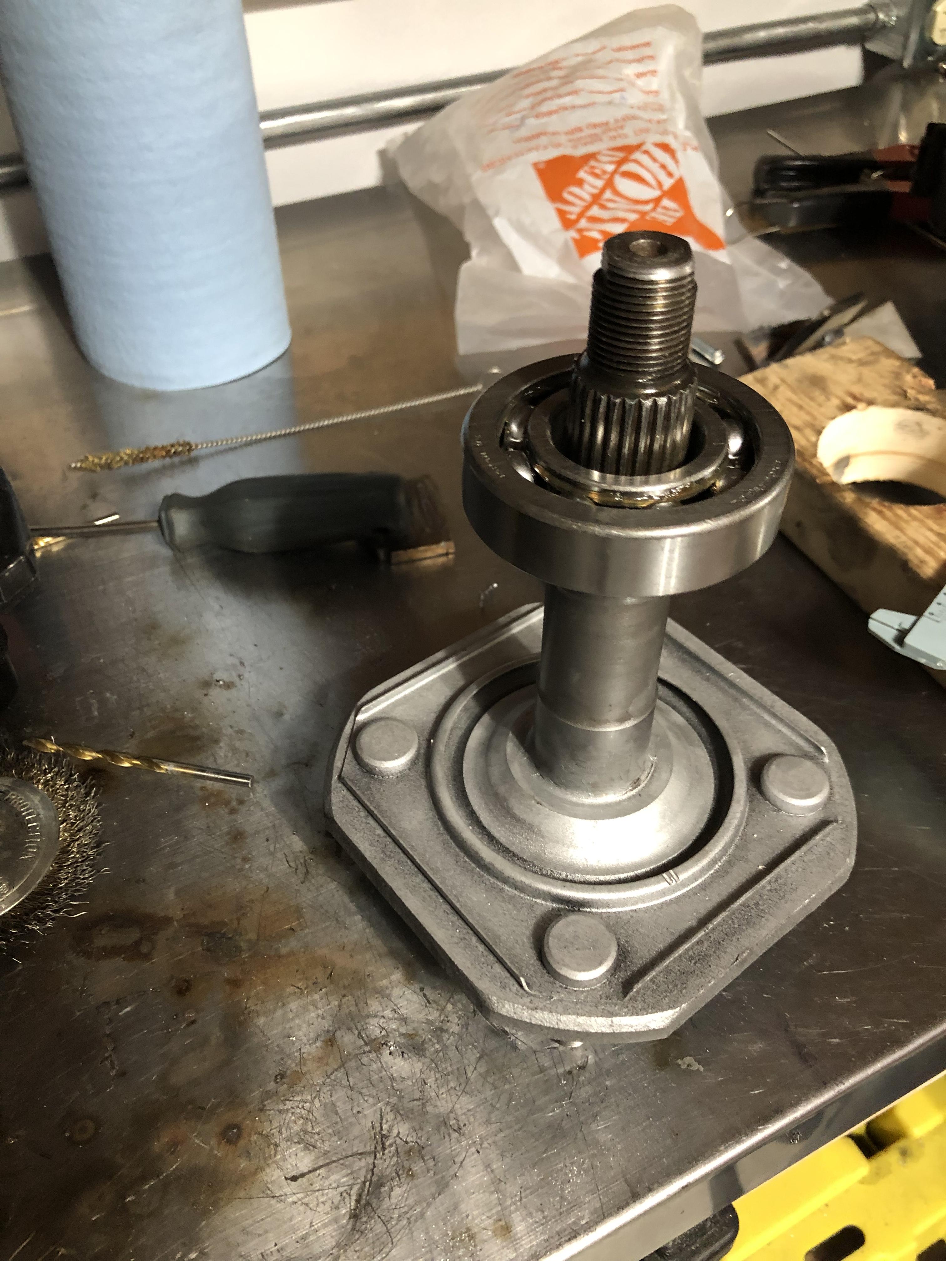
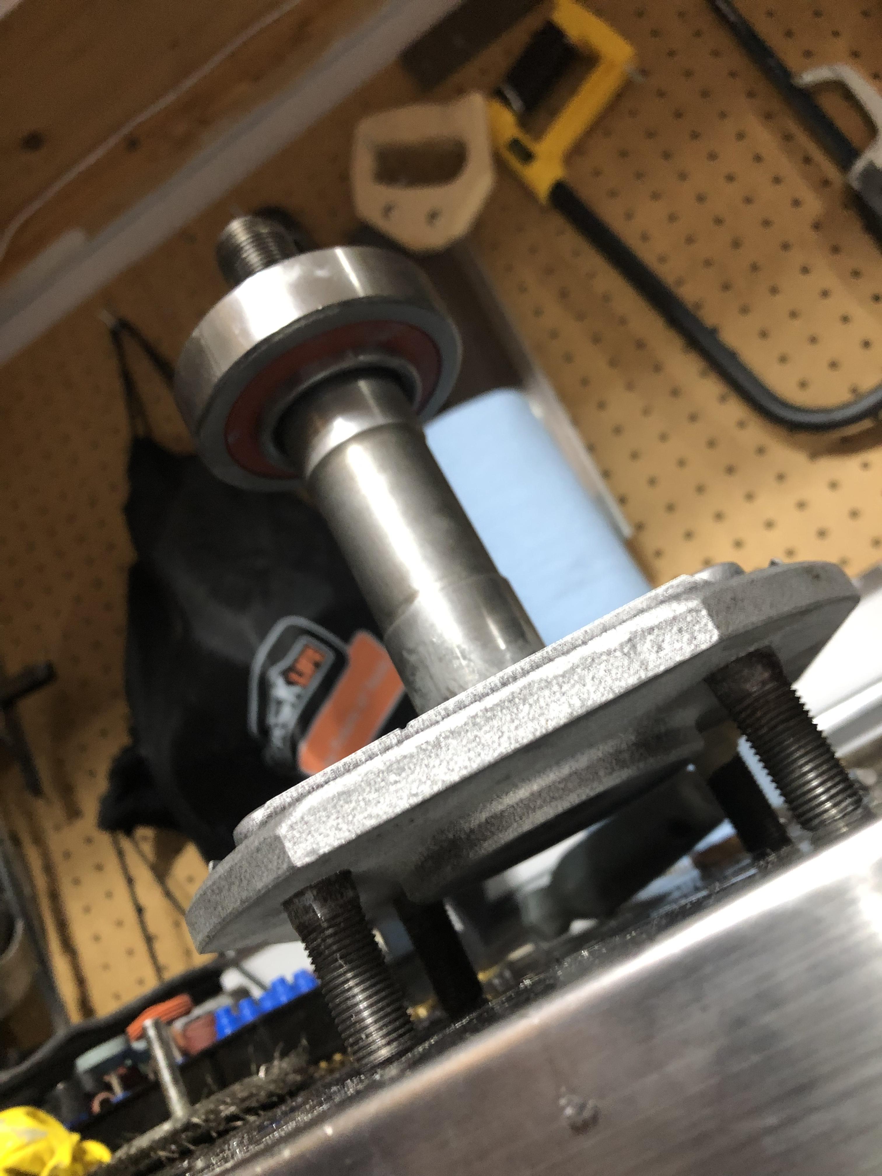
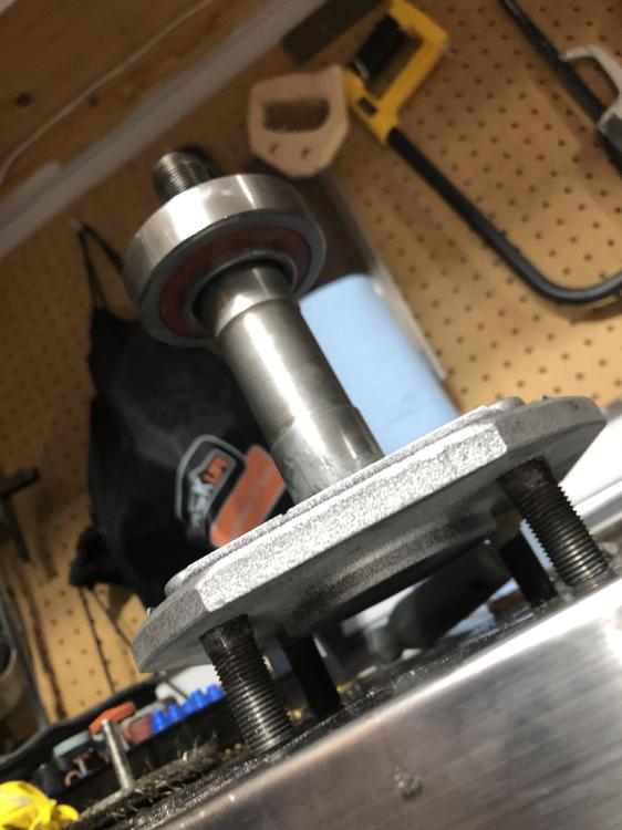
The bearings are from Beck Arnley. The outer is a Japanese made made unit. im not new to installing bearings, what im confused about is the fact the inner bearing seems to be the same diameter as the outer. Sadly I didn’t lube the first section as I expected it to be a smaller diameter and slip right over. With the temperature difference between parts it slid on far enough I can’t remove without getting a little creative and hopefully not damage the bearing. If this is way it is supposed to be, I’ll manage to get it off, refeeeze/heat and be ready to press/tap immediately
-
Hello, i was following the AtlanticZ website when changing my rear wheel bearings. I froze the rear axles, heated the bearing and tried to slip it on. I only got partway onto the inner machined surface for the outer bearing. It seems really odd that I would have to press the bearing over one surface before even getting to the surface it is suppose to mount too. Did I get the wrong bearings?

-
^ That's a definite possibilty.
-
I was under my car the other day, and those drivers side wires are just hanging there. I couldn't remember if it was supposed to be like that but the car still works My engine and transmission have been in and out several times though so it's possible they were dislodged? As for the shifter, my '71 required slight trimming, and the 260z shifter worked fine.
-
Where's this video? ha
-
Exactly, "race cam" is a bit of flakey term. Just like Stage 1, Stage 2 etc that we so often hear. Jibberish. Chickenman, FYI the increase in idle ignition timing in Tune #5 was just a test. I backed it off as I didn't really see any real benefit, and still wanted some real improvement for a idle "correction" in the lower RPM range. 23 degrees worked, for the correction, but I wasn't seeing any real benefit in idle quality. 20 degrees works well for idle, 22 for the low RPM correction. Anyone else with an aftermarket cam have any vacuum readings at idle?
-
It is a P90 head that has been shaved a few times for straightness. The reason the CR is lower is the CC has had some material removed during the porting. The head has never been shaved to increase CR. Cam was degreed properly with an adjustable cam gear. Somewhere along the lines in my learning process I dropped the chain tensioner and ended up putting in an OEM cam gear as I ended up dialing it in at one full tooth advanced(Or was it retarded?) from a "stock setup". Don't ask my why, but now i've lost that adjustable cam gear somewhere in my moves. This all happened in the first couple hundred KM of the rebuild. I ordered a new one just to play around. The slots in the OEM gear are much too large (4 degrees). Reason I am suspicious, is the "Z man of Washington", (A fairly reputable Z business man in PNW) somewhere online stated no matter what cam you have, you should be seeing 14+" at idle unless it's an all out race cam. More curiosities sake then anything else. My car idles pretty decent. But, as you guys both mentioned. A lowish CR wouldn't help the situation. Was more a thread to see what other people are getting. So far, nothing too extreme.
-
Well that's good relevant info for sure. I still need to find a few hours to get the thing running again.
-
Hello everyone. I'm curious what everyone is able to get for idle vacuum with their aftermarket cam. I have a Colt Cams C542.s with the following specifications. Duration @ .50" 224 I/E or 280 degrees valve lift .510 Lobe Seperation 108" Engine is a L28 w/ about 8.7:1 compression. The best I can get using Megasquirt fuel injection is around 10"s. Sometimes jumps into 11" for short periods. Chickenman and I have been playing with the FI for a while now working out bugs, but my vacuum has always seemed a little suspicious to me. Either way, I just ordered a fancy schmancy adjustable cam gear to play around a little bit. What are you guys seeing for readings?
-
Thanks for the pictures madkaw. I used a a holesaw, then fire method on the moustache bar. What a mess. For clean up I tried a few things, but the wire wheel worked best. I'd try a different method next time. I have my control arms being painted in a 2 part epoxy as we speak, it looks like your method here will work without screwing up my new paint. Should have removed the bushings first.
-
Thanks for the quick reply. I havent actually seen the unit in person yet. Ill grab the front diff mount as well, but I do plan on doing an RT mount, and if need be I can use it as the sole mount with a urethane bushing. Once again tha js fir the reply. Ill try and get some cinished photos up too.
-
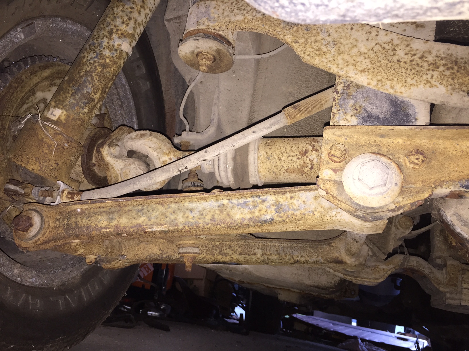
Well, I could be totally wrong but maybe they arent CV's. I believe the car is a 1978.
-
Well, I could be totally wrong but maybe they arent CV's. I believe the car is a 1978.

-
Pulled out my driveline to get easy access to fuel lines (upgrading to 3/8" for turbo charger) on my 1971 240z. Everyone knows the "while I'm at it" way of doing things.... I'm upgrading my rear end. I purchased the rear end from a 280z 2+2. Its an R200 with the CV axles. I will be stealing the mustache bar as well. Does anyone know if I'm going to have issues mounting the CV style axles onto my 240z hubs? Or am I going to have to source out some universal style R200 stub axles to get this setup to work properly? I figured it was easier to strip and paint one set of drivetrain rsther then doing it, then having to upgrade. Cheers
-
Well, I didn't have a properly working multimeter (resistance readings are way off), I wired in the small resistor and switched to the other prong as discussed above. 14.6v at idle! Wowsers. We'll chalk this one up as a success story.
-
I ran 0.021" over deck, with my pistons, and a 1mm mls gasket and the car ran, never hard though (has having guide issues). Eventually switched to .050 mls after reading Bryan Blake's post. Curious how yours works out.
-
Thanks for doing the research. The original 4 pin layout explanation was off that pirate4x4 site as well, but on the forum. I missed that write up, that's a good one. Unfortunatly this is going to have to wait until mon/tues to solve this riddle now. I will do as you say, and check the resistance in the circuit, will have to purchased a new multimeter as mine gives bogus resistant readings. I also purchased a 46ohm resistor which should do the job nicely. Once again, really appreciate the help. I think we figured out this problem. I will update you all.
-
No, thanks zed head. Really appreciate your input. The '71 manual is the one which is missing in the library so I'm weary of believing the newer model diagram. All I know is I don't have a light (it's in the console correct). Hopefully someone can answer this as it's really tempting to just swap prongs, and start it up.