ensys
Free Member
-
Joined
-
Last visited
-
Mr.Patcon: Clearly, the obvious best solution, and one I would have pursued were I not machine-tool disadvantaged. But then, the situation with press-fit gears on the spindle shafts has been previously well addressed. The core issue of this thread is the symptoms of failed pick-up coils, the potential dire consequences in the event of their non-performance/failure, the complication of diagnosing such a non-performance/failure, and the current difficulties in sourcing properly operating replacements. Bottom line, beware of Standard Products' replacement pick-up coils, and of Rock Auto's lack of due diligence in distributing products that are well below an acceptable level of performance. As consumers, we should demand better. Just $.02 from the cheap seats.
-
Right you are: a '77 280Z that until this year, was still running, after 200k mi., on the original distributor (with orig. pick-up coil) without incident. But all good things must come to an end, and for the p-u coil, this resulted in ignition spasms that increased in occurence and duration of undrivable operation, until there was only a good idle with hellacious mis-firing (with much shake, rattle, and roll) at any revs above that. Like you, I never suspected the p-u coil's fault and spent much time and money looking for the source of the ugly behavior. When it came down to "I've tried everything else", I bought the first replacement coil, the installation of which resulted in the very same behavior, so I kept looking elsewhere. Three months later, I was back to "I've tried everything else" again, and I bought another replacement, thinking the crappy condition of the first upon receipt may have been more meaningful than I thought. Sadly, the second would not produce any spark at all. DOA. Mind you, all three passed the only test specified in the FSM, the check of resistance of the coil. In between the two, I had purchased a "rebuilt" distributor body, as a despirate extension of my earlier "throw fresher parts at the problem" that resulted in a replacement ECU and ICM (among other parts), all to no avail. It was this distributor body that brought the p-u coil that looked to be out of some other application, along with some other oddities. Finally, having little hair left to pull out in frustration after the utter failure of the second "new" p-u coil, I threw that puppy (the "rebuilt" distributor... (30Sep. edit)) in for lack of any other approaches to the problem. Lo and Behold, the engine got sweet once again! I was astounded. I moved the p-u coil to my own already rebuilt distributor (with its fresh cage and new bearing balls), and the engine is running fine once again. There is a larger moral to this tale of woe; as a result of the violent behavior during the first p-u coil's recurring spasms of slow failure, the crank nose drive gears began to shear their keys and spun the distributor/oil pump drive gear press-fit on the spindle shaft. Fortunately, we're only talking a few degrees, and with the deployment of a new spindle shaft, I have been able to dial in a usable ignition timing for the time being; tho I know that when time and opportunity permits, I will have to address the crank drive gears in a more meaningful manner. Thus, I urge you, Gentle Readers, to never take misfires lightly.
-
My bad. Ignition Pick-Up Coil. In the distributor.
-
Gentle Readers: Has no one else noticed that the current supply of Pick-Up Coils has gotten very dicey of late? In the course of this summer (Jun. and Aug.) I have purchased two such coils (from RockAuto), only to find that both were hopelessly inoperative. Both were sourced from Standard Products, and while both exhibited proper resistances (the only (short of oscilloscope exam) test promoted by the FSM), both were useless in actual operation. Of course, since the opportunity to test either occurred outside of the narrow "warranty" period, I've had to eat the cost of both, leaving me highly skeptical of Standard Products in specific and Rock Auto in general. Which leaves me to wonder; am I the only one to be in need of Pick-Up Coils, and if not, what are others doing in the face of this dearth of this part so necessary to proper ignition. I will note that the only thing that has allowed acceptable operation, has been the deployment of a No-Name, oddly configured coil out of a none-to-precise "rebuilt" distributor body purchased during my get-new-parts phase of problem-solving. So, again, what has worked for everyone else?
-
Apparently, their web site doesn't know it yet....
-
RE: Distributor mechanical advance weights. While I cannot name the source (other than noting it was not the FSM), I am led to believe that the total mechanical advance is identified by a stamping on one of the weight pairs; i.e., "8.5" would denote a pair that provides 17deg. of total mechanical advance, etc. Can anyone confirm or correct? Source? I thank you for your attention.
-
Mr.Head: As is as no surprise, right you are... And is my face red; I've had much occasion to pore over this section a number of times, but somehow I was blind to the facts before my old eyes. Thanks for not rubbing it in...
-
RE: Stock '77 280Z vacuum module Would anyone in these parts happen to know the specs (in inches/Hg provided for full advance) of the Factory distributor vacuum module? I thank you for your attention.
-
Mr.J: I've told myself that your brand of Trolling is sometimes the price of online discourse, but I cannot help wondering... What is your problem? Did I call your dog some dirty name? Why the naked hostility that turns what has been intended as a simple discussion about an arcane and impersonal issue of technical interest, into some battle of wills? Is this really the proper place to work out your anger issues? Mr.Head: What have you got against attempting original thought? There are many ways to skin a cat, no? What is wrong about finding one more? Peace on you both.
-
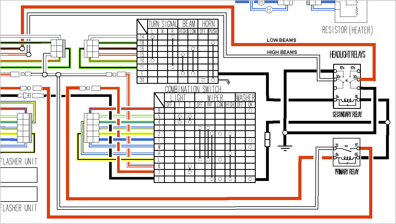
Gentle Readers: Please note that the image in the post above has been edited (replaced) to more accurately reflect the intended configuration. Specifically, the first posted image erred in its depiction of the power feed into the high beam circuit to activate the beam relay coil. My apologies for the posting error.
-
Well Folks, I'm back, confident that all here can get past previous personal issues, to lend a helping hand toward finding a workable solution for an issue of our common interest in the beloved Zs. I believe this latest Version reflects the very helpful advice most generously offered previously, and I am hopeful it is much closer to being successful. Adjustments in this iteration:: Correction of a graphics error (my Bad) that wrongly depicted the low beam feed to the relay as a "tap" instead of the intended "diversion". Mr.J, I now see where you were coming from; and of course, based on the evidence I provided (again,my Bad), you were, at least on this point, spot on. Corrected an error by changing the default of the beam relay from "coil-energized" to "not-energized" (i.e., low beam default). Moved the routing of power from the Fusible Link to the hi beam circuit in the switch, to the input side of the connector, to reduce the number of connector pins that must be removed from the plug. Simplify, simplify... Added a new chassis ground for the beam relay feeds, instead of pointlessly running the currents back thru the combo switch to reach ground. This lessenes the current work load on the switch and simplifies the required wiring. Thus, I can reduce excess (new) wiring, enhancing the elegance of the solution. Thus, the clown willingly once again climbs upon the dunk-tank seat with the hopeful expectation that the sharp-shooters in the crowd will give me any splash I deserve. Call it learning with a bath; I can only end up cleaner than when I started, my idea of a viable definition of learning, GentlePersons, once again, I thank you for your attention.
-
Indeed; well at least you're proving that it's never too late.
-
Mr.Head: It was the hdlite rotary power sw. issue (that I began to appreciate when I had the combo sw. apart looking for lost "enlightenment") that got me started with relays. But it was what I found to be the cause for the sporadic issues with hi/low sw. operation that made the second relay look like a good idea too. After that, it simply became the fetish for a minimally-invasive elegant solution that would not, even in unseen ways, compromise the fairly remarkable originally of the Trusty Z. Text book Obsessive/Compulsive I suppose, but hey...
-
Mr.J: Well, then. I wonder; when you were introduced to Calculus, did you ever diligently struggle with a difficult problem solution unsuccessfully several times, just to have your Teacher advise disrespectfully, that you should burn your math book? Somehow, I don't believe you would have quit, and nor will I. However, I will continue my education on a new thread; I apologize to the Forum for the interruption of the original discussion focus of this thread.
-
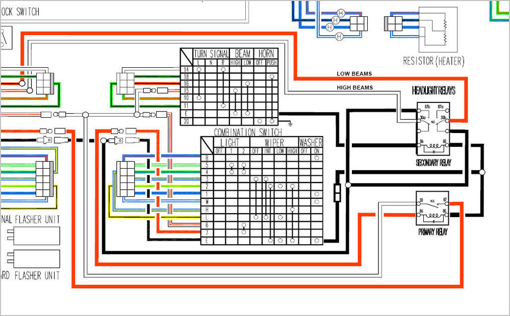
Hello Folks: I do appreciatively applaud the effort to provide the switching bits that time has forgetten; rest assured that I'll be in the line to obtain those parts that make the combo switches work at their peak again. That being said, I hope I will be forgiven for taking a sharp left at Mr.Head's post #14, regarding the concept of Relay Options that minimize the high-amp effects on the stock combo switch configuration of the equipment (old or new). I have studied the issue of electrical stress on the Combo switch, and while I make no claim to Electrical Engineering proficiency, I have come up with a diagram that would, in my ignorance, seem to be a workable integration of 30amp relays as a workaround for the effects of routing amp-heavy loads thru the two Combo switches. Thus, I would humbly offer this potential solution that seeks to provide all the stock switch functions, without running big-amp loads thru the actual combos. I would note that with but a couple exceptions, the current version does not require substantial alterations to the stock harness (the exceptions are centered around connections to a couple plug bodies). I proffer this proposal with the express purpose of soliciting critical feedback from any and all among this august body of readers, hoping they can show me the errors of my construction, thus enhancing a better solution for all. I whole-heartedly encourage corrections/alterations/thoughtful crits to the following diagram (which depends on my ability to insert a jpg (and no, I can make no promises here either}) .... If you please, look this over and share your improvements for our mutual benefit. I thank you for your attention. P.S.: Wouldn't cha know it: I've just noted a connector graphic error at the interception of the incoming red/white hot line. Very embarrassing.