ensys
Free Member
-
Joined
-
Last visited
Everything posted by ensys
-
RE: early '77 280Z Ever seen that theatrical party skit where some sober soul (let's call him Mr.Fairface) is hypnootized for a lark, so that at the utterance of a "trigger" word, he is immediately transformed into Mr.Uglyface, a roaring drunk? Then, with the trigger word, Mr.Fairface is back, etc. This, gentle reader, is the apt illustration of my Z problem. Mr.Happyface is a happy, sweet running engine with a strong, clear idle, a sweet sensitivity to a gentle tip-in of the throttle, and a strong, sure pull from almost any rpm. A true baseline of operation that would do any mechanic proud. Mr.Uglyface is a cranky, ill mannered motor that refuses to idle, won't tolerate throttle, and which bucks and lurches up to about 2K rpm, if you can get it that high. On the way, while you're trying to clear its throat, it farts light grey mist from the tail pipe. A plug read in the wake of Mr.Uglyface screams "way too rich", which pretty much eliminates fuel pump issues. But here's the punchline: the change from either face to the other happens like someone spoke the trigger word, or threw a switch (in electrical terms). And the transitions are independent of coolant temperature. And it still happens if I unplug the CSV. Oh, and the CTS is new, and given the natural action of a thermocouple, I would rule out its ability to produce instantaneous changes. I tend to also exclude the AAR for the same reason. Also, the TPS has been carefully calibrated from the start. In use, despite my fiddlings with the AFM, the idle mix, timing, checking vacuums, etc., the periods of Mr.Uglyface are becoming more frequent and are lasting longer. Crazy, huh? Any thoughts?
-
Well, I wouldn't be too sure about that. My '77 is an original Cal. car, and it came well treated with the then conventional asphalt-based undercoat. Not terribly neatly, but thorough.
-
I can't help wondering.... I have seen OEM parts for other old cars, some produced after the series production for which they were intended, that had a protective coating to enhance their shelf life. Just a thought...
-
Maybe not, but you're certainly losing. But hey, who's keeping score? You?
-
Mr.Head: My, aren't you the helpful fellow. I can tell you I appreciate the effort, no matter how aspirational it may be. A clumsy attempt at cutesy sarcasm to be sure, but you have unknowingly added the icing on this half-baked cake of boorish behavior. "why are you here?" Exactly. While the first post of this thread was quite specific about its purpose (help solve an electrical problem), by the fourth post, that train of thought had been switched to the siding of personality issues, so it's no wonder that you (and the others) have forgotten the point. I reckon it's that attention-span thing. I know I'm tired of this lame excuse for repartee that has nothing to do with the electrical systems of a Z, a subject that can inspire more widespread interest than a dust-up by the kids on the playground. Believe it or else, there are a respectable number of sincere enthusiasts that would like to know about wiring diagram issues beyond the kerfuffle over a mistake I acknowledged immediately. Still waiting in the wings are diagram issues that could effect the pursuit of problem solutions for 280Z owners. After all, isn't that kind of information sharing the whole idea of this joint; or have hissy fits, cat fights, and ego-strutting become the forum's reason for existence. Which do you think it should be, Mr.Mike? And while I have your attention Sir, got any ideas about how I lost the ability to post an image in just 30-some days (with no changes in equipment or programs, and over three different platforms)? Inquiring minds want to know...
-
Mr.Head: Et tu, Brutus? Just when I thought you had a handle on something besides a knife. Let me set you straight: Not being possessed of a fragile ego, asking questions, seeking learned advice, or occasionally putting my foot in my mouth in the process, has never been a problem issue for me; it's how one learns. That is, until I started to do so around here, which is more akin to putting a target on your back.. By the same token, it never occurs to me that "gracious" is the correct response to ill-mannered behavior and hostile demeanor, in what is supposed to be a civil and non-judgmental conversation about cars. If one expects "thank you sir, may I have another" after none-too-subtle pokes in the eye, yer barkin' up the wrong tree. You're right about one thing tho: My Bad for not better adjusting my presentations to suit the lower common denominator of this specific audience. So of course, I must take the blame for optimistically assuming an inappropriate level of reading skill, attention span, and comprehension, let alone any real desire to communicate that which does not enhance a web image or provoke a laff, especially at someone else's expense. And of course, in certain circles here, literacy earns extra penalty points. But I'm learning... much that has nothing to do with Zs.
-
Thank you Mr.Head for injecting a note of maturity among this mean-spirited nattering of adolescent bully boys. The only effect I'm trying to achieve is clarity, and hopefully with a little panache. Apparently, this scares some folks, tho I can't, no, I don't want to imagine why. Yes, a problem was solved, but not without the price of being the butt of derision. Frankly, the "brilliance" of the solution was not worth it. Still, it's my own fault for misjudging the situation. I made the error of assuming that helpful advice is more important than stroking egos, and that shared problem solving is more entertaining than seizing/fabricating any reason to ridicule and insult. It's my bad for forgetting these very lessons from the last thread. I should have known that for some folks, asking for help on this forum is taken as a sign of weakness. I don't think that's how this is supposed to work, but it's my bad for forgetting that no one here ever needs a hand or makes a mistake. It's also my fault for not realizing that reading comprehension is so obviously in short supply, as its lack is the true source of the petty and pointless dialogs in reply. And of course, my biggest error was in assuming I am dealing with adults, not high school rowdies, making fun of the kid with glasses. I'll keep this in mind in the future and lower my expectations accordingly. And yes, I would still like to know why I cannot now post images, when I could a month ago.
-
Mr.C.O.: You have aptly demonstrated the value of a fresh perspective. So my Kudos to you, Sir You're half wrong (no.1), but I think you're spot on with no.2, and I'm embarrassed that I did not see it, given the obvious clues. Clearly, not my shinning moment in Deductive Logic. Too many follow-the-wires distractions to notice the diagram's indication of identical harness plugs for the two indicators. I reckon if I had re-installed the seat belt indicator, I would have seen this sooner. I'll have to verify of course, but as that will require doing the inconvenient unmounting of the console (it's gotten quite crowded back there, making the fit something of a pain), it will probably be a while (not the most pressing issue on my to-do list) before I do. Now, if someone could figure out why I suddenly cannot post jpegs, we could talk about the diagram errors....
-
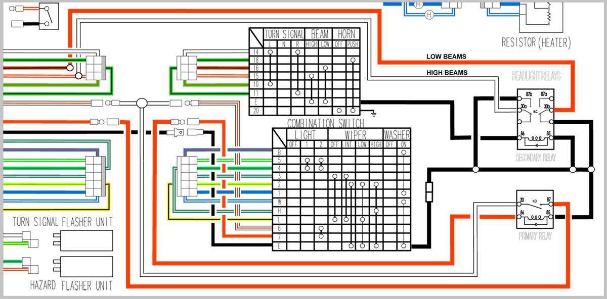
Today's saga is lifted from the pages of reality... In the course of the re-install of the '77 280's floor console, I discovered an anomaly in the operation of the hatch window Defogger; the switch activates the heating grid, but not the indicator at the console. No need to chase a bulb issue tho, as switching the ign. to "On" activates a "test" cycle (that is clearly operated by the "Seat Belt Warning Timer located in the relay group in the pass. footwell) that successfully activates the Defog indicator for a few seconds, so clearly the fault in not in the indicator. Nor is it in the connectors of each to the main harness, as all are original plugs that are clean and properly connected. Some intensive research using the wiring diagrams from both the FSM and the most excellent ClassicZcar version, resulted only in two interesting questions: Why does the Defog switch operate the heating elements, but not the indicator? How is the indicator connected to the Timer? This last is particularly vexing, as none of the diagrams in the FSM, nor the CZc version indicate any connection whatsoever (that I can see) to the timer relay. Not thru the switch, nor the Defogger relay, nor the ign. relay or F.I. relay. So there's the challenge. Any takers? Of collateral interest: While poring over the diagrams, I became aware of three new (to me) errors in the CZc version, one of which is shared with the Factory full diagram. As they would be difficult to describe verbally (a process fraught with opportunities for misunderstanding), I had prepared a small (220k.) .jpg as a visual aid, only to discover that apparently my "uploading" mojo has failed/been foiled in the last 30 days, prohibiting its posting. So the short form verbal is that they involve the internal diagrams of the Defog and Ign. relays and their connection to Body Ground. Of the bunch, the sudden inability to upload is the most perplexing and annoying, so a reasonable answer to this is worth Big Bonus Points. Any takers?
-
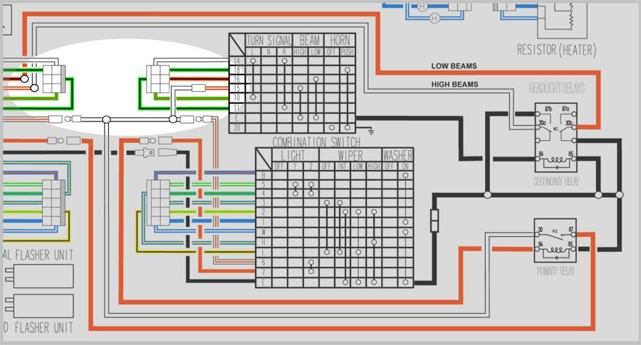
You can put your hand down Mr.Obvious; we saw them the first time. I'm sure they're fine solutions in their own right, but as none meet the critical criteria of my particular project goals, they are still of no interest to me. To Work: Plan C This iteration taps the nearby feed from the fusible links to provide a switchable and unencumbered source for the Secondary Relay's coil. I believe this resolves the previous issue of contention. The question is, are there more in the wings. The area of change is highlighted on the detail below.
-
Sorry I didn't meet your standards.
-
Mr.J: When you put that way.... I don't want to seem ungrateful for the properly explicit analysis, but you could have saved us both a lot of verbiage, if you had said as much 3 or 4 posts ago. But hey, better late than never. Clearly, I am painted into a very tricky corner. Well, if at first you don't succeed... it's back to the drawing board. While I do not yet know how to best use this information, it does make clear the wisdom of getting input from those whose understanding of some complex situation exceeds one's own. I'd like to thank you Mr.J (and all that generously offered something helpful) for your patience and expertise. But as a man once said, "I'll be back". Call it a fetish.
-
Mr.J: First and foremost, I appreciate your persistence in the effort to offer constructive criticism. Thank you. Editorial sidebar: However, as the Man once said, "what we have here is a failure to communicate". The first issue is mine, as my old eyes have great difficulty in distinguishing the colors in which your stick-figure diagram is rendered. Add to this that one cannot distinguish a connection from a crossing and, for me, confusion has its head. And frankly, the decision to use your own line colors instead of those in the diagram we are actually discussing, doesn't promote clarity. So I hope you will understand that my comments will always reference those colors in my presentation diagram. While I can understand feeling a need to dumb things down enough for the challenged to get your point, I would again submit that your simplifications are too extreme and at the cost of relevant details. But, to work. Off the top, I have two big clouds of fog that obscure my vision of truth: Fist is wonder how you consider the relay coil to be in series in the feed flow from both headlights. While I have often felt my ignorance is boundless, I have long thought that I know a parallel circuit when I see one, like, as shown in your first diagram, and in mine. Again, when two circuits start and stop at the same points, is this not a parallel circuit? I would maintain that your garage experiment did not replicate the situation accurately. Second, for the life of me, I cannot grasp this business of disappearing current once the coil is energized. The feed presents the same voltage for both legs at the Y, and both legs of the parallel circuit possess the same potential current differential to ground, yes? This one stumps me. Of course, I designed it as a parallel circuit... Perhaps clarity would come from you addressing just these two issues, should you still be inclined to help. Here's something else I don't know (the list is getting long, eh?): how big is the window of voltage tolerance for a typical 12v relay coil? Does it vary with the number of contacts? By the by, are we in agreement about the Power relay being workable as shown? Nice math; shows a laudable dexterity. No sense in quibbling about the assumptions, like that the coil is in series and on only one headlight circuit. I don't think the corrections would change the fundamental issues here. Now, I don't mean to be a difficult student, but I'm getting a feeling that your not really reading my homework. Keep those cards and letters coming folks. Like the clown at the dunk tank, I'll take all shots, as long as you hit the bullseye of addressing the topic/approach at hand.
-
Mr.J: With all due respect for your obvious acumen, I believe that your diagram has simplified some germane events out of the circuits. And while the narrative may simply be beyond my grasp, some elements puzzle me. With your indulgence, I would hope some dialog might illuminate my errors. Following the path of your narrative, let us begin with the Secondary relay: While I acknowledge that the metaphor of hi/low switch removal baffles me (as does the notion that the HL could somehow operate without it), it is the case that the returning hi (wh/red) and low (blk/red) HL circuit wires both have 12v potential on their way to the switch, looking for ground. However, please note that the low bm. circuit is diverted before the connector, leaving only the hi beam circuit to enter the switch to become the coil activator for the Secondary relay via the (e) ground path when hi bms. are selected. Thus, low bms. are the relay default when HL are activated, by virtue of no current to the coil, and the N.C. low bm. switch in the relay. My problem is in seeing how this arrangement would leave too little current to power the low-amp coil draw. And while being wrong is always on the table for me, isn't it the case that when two circuits share a common source and termination, they are in parallel? Wouldn't this obviate the whole "voltage drop" thing? I understand the "norm" of design you describe, but hey, flow is flow. Dipping into circuits to power their own flow control seems little different than the multitude of taps and diversions that are characteristic of every harness. Besides, in a lighting circuit, what is the actual consequence of the failure of the coil circuit, when the flow it controls fails? To me, this is the essence of a "moot point". If I seem stubborn in my ignorance, it's because I am strongly motivated by the potential elegance of a solution that integrates into the function of two complex switches to accomplish their functions in a different way, while providing operation indistinguishable from original, without a single permanent alteration of the orig. harness. Call it a fetish. Finally, yeah well, if I was smart, I wouldn't fool around with old cars because I am entranced by their time machine qualities. Or; if I wanted the affliction/affectation of hi-tek, I'd drive newer cars. So, Sir, in full realization that I risk exposure of being electrically inept, I fervently hope my narrative will help my on-going education.. Please, fire away.one and all.
-
Now that's what I'm talkin' about. I thank you Mr.J for your thoughtful contribution. Since my forte runs more to structural than electrical engineering, I must beg some patience with my slow grip. I will have to chew on this a bit before I can offer a proper rely. More later, and again, my thanks for helping me out.
-
Mr.K: Well, there we are; I wasn't working with a '76 wiring diag. and you don't have one for '77. I don't know what to tell you about the differences between them, but I used the familiar "Classic Zcar" version, which I have found to be quite accurate for '77s like my own. Meanwhile, while my relay diagrams may not be mechanically precise, but they are diagrammatically correct, taken from those shown for the respective relays. Still, I appreciate a continuing education; for example, I have never seen a 2-pole relay that is both Normally Open and Normally Closed at the same time. Live and learn. Mr.C.O.: What makes you think it isn't? You tell me. After all, isn't that the point of such discussions among learned gentlemen? I must admit Sir, that it's hard to find anything constructive in baseless scoffing at my temerity for trying a clean-sheet solution. I'm not selling anything, nor am I here shouting "Eureka, ain't I great?"; I'm looking for someone to tell me where I go wrong. What would be constructive would be some clear representations of a few of those time-tested solutions of which you speak. Especially those that preserve all the functions of the (e) controls and indicators without materially altering the stock harness. I'll look forward to that. Again, all constructive criticism is welcome. We're all here to learn from each other, are we not?
-
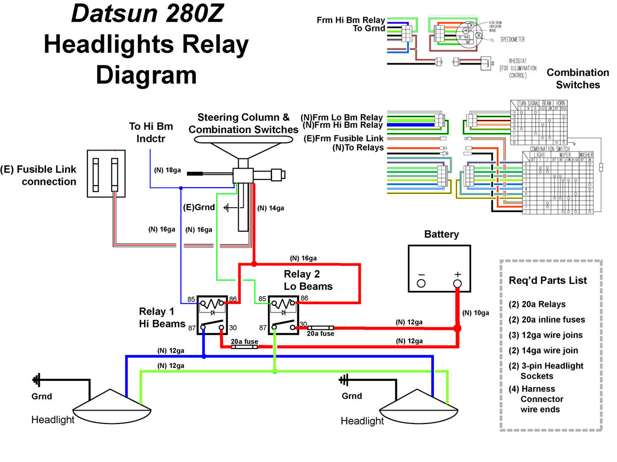
Mr.K: Well, I think you'll find that the hot in is at pin 6, arriving on the red/wh directly from the fusible links. The red out of pin 7 goes to the fuse box where it feed the R and L headlights. I interrupt this feed to energize the Power Rely coil when HL are selected from the switch. This event then directly connects the hot feed from the F.L. to the feed to the HL at the fuse block Also, the Power Relay is N.O. as shown. Energizing the coil closes the switch, powering the H.L. This would be a good time to note that despite the fact that the (e) fuse deployment should continue to provide sufficient circuit protection, I am mulling the idea of introducing additional fuse(s) within the added circuits. Call it the spirit of suspenders and a belt.... Any thoughts?
-
For your consideration; Plan B I believe this configuration will preserve all the original switch and indication functions with the least alteration of the (e) wiring. I invite your comments.

-
Well folks, it's gratifying to see some feedback. Education never ends... First, some comments: - The relay diagrams were lifted from actual relays, chosen purposely with the integrated backfeed buffers (diodes, etc.). I acknowledge that the buffers may not be necessary in this case, but I like the sense of extra finesse. Also, my decision process was influenced by a more intimate knowledge of my own driving habits that employ a more frequent use of beam-switching than may the norm for many. Low-to-hi-and-back-again, plus flashing, added to simple on-and-off, adds up, by my reckoning, to quite a few cycles during typical night road work. - Same principle at work with the choice of wire ga. As I am not planning production of umteen thousands of units, I like to afford myself the luxury of over design in wiring. - I concede that the fuse choices are probably over-kill, again out of caution (15a would likely be a still prudent choice), but easy replacement makes refinement simple. Finally, I will note that since posting this postulation, I have made a few alterations in the design, including a change to an 8 pole relay to control the hi-low circuits, and a 4 pole to control on-off. Of course, this flow required several routing changes, all devised to more accurately emulate the operation of the original configuration of inter-related column switches. I'll post a revised presentation as soon as time allows. I thank you for your interest and valuable critiques.
-
Mr.1: I don't know what your size limits are, but it occurs to me that a more popular (and rare) part might yield a better return, while satisfying a pent-up demand. I'm thinking of the inner shell of the Factory console bin lid. Everyone likes them and they are NLA in their stock form. The beauty of the piece is that it is hidden (beneath the soft cover on the outside and a plate on the inside), so "finish" is not an issue, and that it could be re-engineered to provide much heavier screw-socket posts, the single biggest cause of death of the originals. While finding a intact original will be impossible, even a dead one would provide the needed post locations. Just a thought....
-
Now, that's what I call rugged nonchalance. Me, I'd be a nervous as a long-tailed cat in a room full of rocking chairs that my expensively tricked out V12 would be ingesting dust, dirt, leaves, candy wrappers, rain from an unexpected squall, or the Big Gulp of some passing mope with no conscience while out running errands, or would become low-rise condominiums for the mice in the garage. Kudos for your nerve. But really, what's the story about those wheels and two-sizes-too-small tires. Automatic speed limiters? Science experiment? Bold aero exercise? What pressures do you run to keep the beads in contact with the rims, so far away from the edge of the tread? Inquiring minds want to know.
-
That's quite a snootfull alright. Ought to have some interesting handling qualities. Especially with those wheels and tires... Takes me back to '64 Chebbies roaming the barrios back in the eighties. Of course, it's obvious from the lack of air cleaners that it wasn't meant to actually be driven. Looks good standing still tho.
-
So, here's a new 280Z headlight relay wiring diag. that needs some vetting by experienced minds. As will become apparent, this is no quickie solution, as it entails reversible modifications at a couple connectors and a few hard-to-source parts. On the plus side, it addresses issues like low-amp switching at the rotary combination, using the (E) power source for relay actuation, and allows keeping the relays inside the cabin. Plus, it includes the Hi-Beam indicator on the Speedo and it frees two spots at the fuse panel (fog lights?). Note: the fuses are sized for stock incandescents, but the wire sizes will accommodate hotter bulbs. So look it over and, if you will, offer corrections/adjustments as needed. If elements look familiar, it's because the diag. was built on the bones of a previous effort for 240s (with a special thanks to it's Author). Your attention, help, and support are appreciated.

-
Mr.Grit: Well, you've certainly been given a whole bunch of issues to attack, eh? That's called "mental dazzle", and is the enemy of a methodical approach. If I may be so bold, I would suggest that since you know the injectors work just fine, the logical place to begin is with the Cold Start Valve. When you look it up in the Shop Manual, you will see that it is itself, a single injector mounted in the intake tract before the manifold. It's job is to act as an electronic choke that enriches the starting mixture for a "cold" (a term that has more to do with engine temperature than air temperature) engine. It is controlled by the Thermotime switch, much like a choke pull-off. Your job is to first see whether or not it is squirting at startup, usually by dismounting it (still connected electrically) and aiming it into a jar while someone starts the car, as the Manual directs. If it squirts (which I doubt), you can check it off the To-Do list. If not, the fun begins. The Manual will guide the way. Bon chance
-
Well, I'm no "Pro" either, but.... Generally speaking, a head is considered flat if it is within a few thousands across opposite corners. Presumably, if he wants to cut .005", the amount of "out" is likely on the order of something between .001 and .003 and he wants, of course, to cut thru it to "flat". Were it I, keeping in mind that once cut, you can't put it back, and that every cut is another chance for an error that can easily exceed the presumed current amount of "out", I would demure the risk, figuring that torquing it up would pull things right. Besides, be aware that every head cut complicates something; in this case, the cam timing. If you must have an increase in the C.R., I would suggest it would be better worked out with pistons for more control. As for the seat condition, it would seem your machinist has a talent for understatement. While I don't know everything that can happen to a valve seat, that is certainly the most remarkable situation I have ever seen. As I don't believe it's possible for a solid seat to vertically shear off an outer segment against an alloy socket, I cannot help but deduce that some mope has tried to shim a seat into an enlarged/poorly cut pocket. And from the look of things, it seems very possible (even if a "guide-centric" cutter was used on the seat) that the valve that lives there has been hitting the seat off-center since the bodge was perpetrated. Since it would seem he has not noticed as much, I would suggest a second opinion regarding valve/guide wear and square. In any case, this will take some talent to rectify, and you might want to wait for the outcome before making any decisions on other operations. Ironically, the owner who commissioned this bit of whimsy, probably trusted his machinist to make all the decisions. $.02 from the peanut gallery.