
ConVerTT
Free Member
-
Joined
-
Last visited
Everything posted by ConVerTT
-
-
-
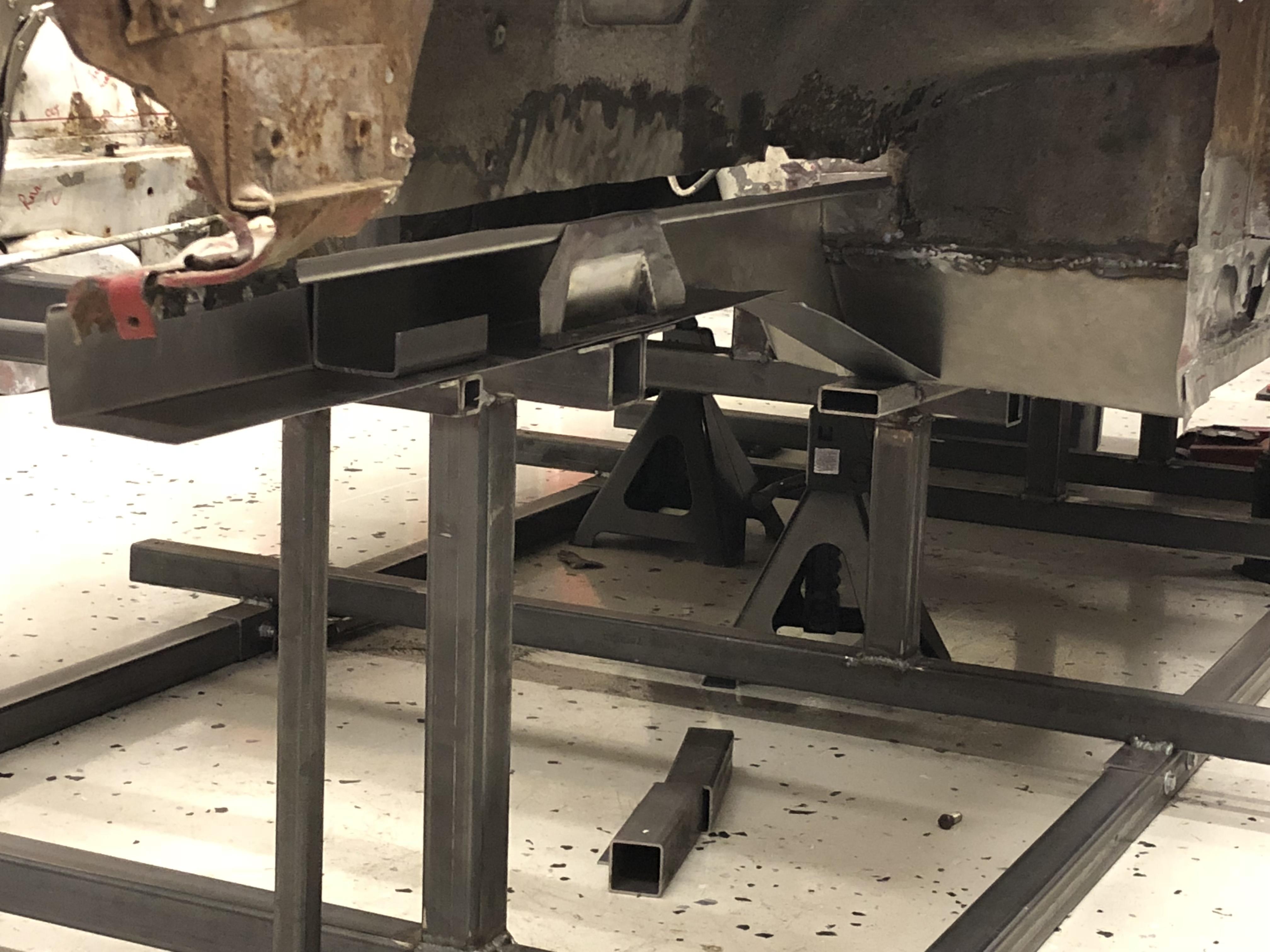
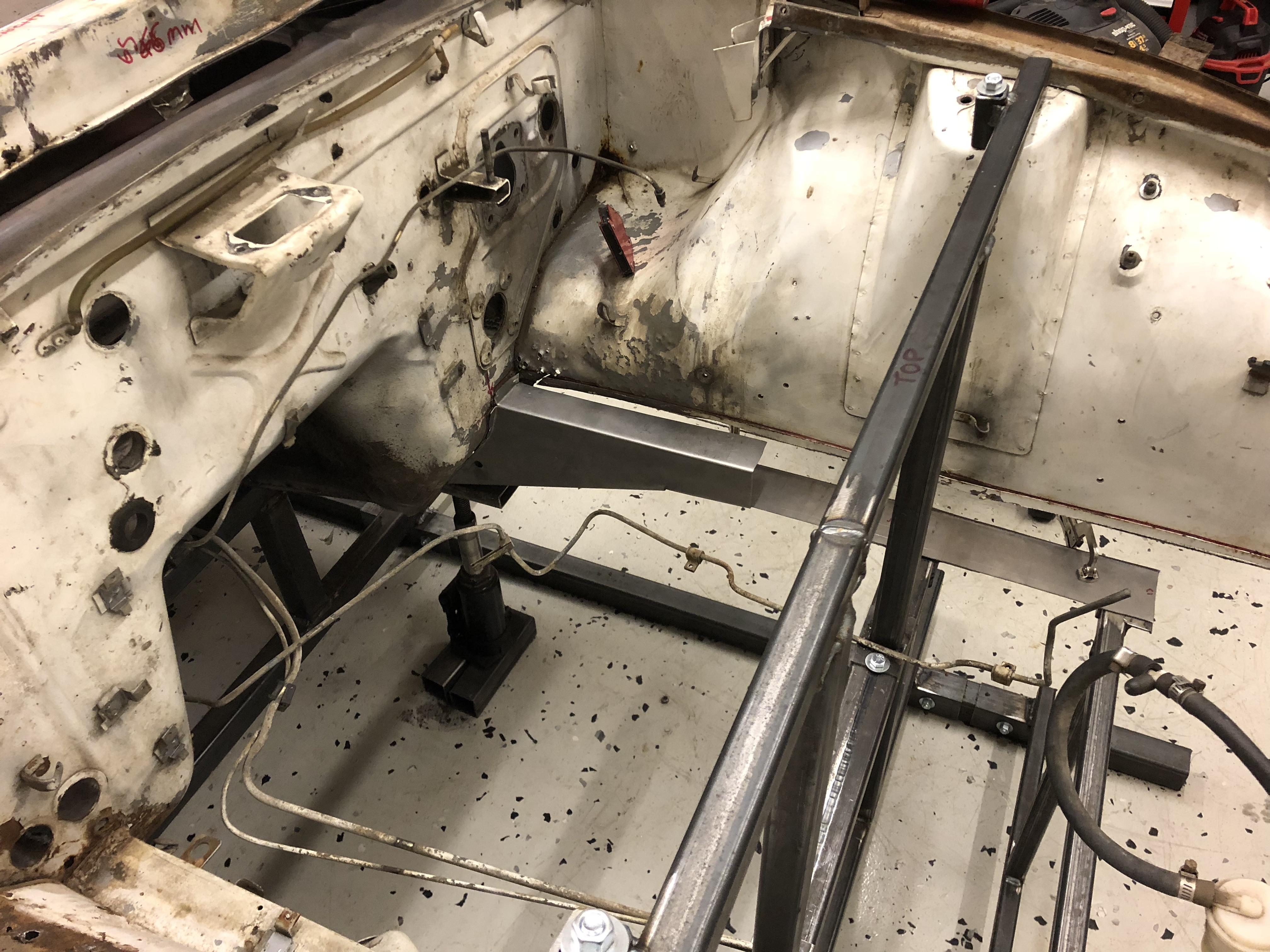
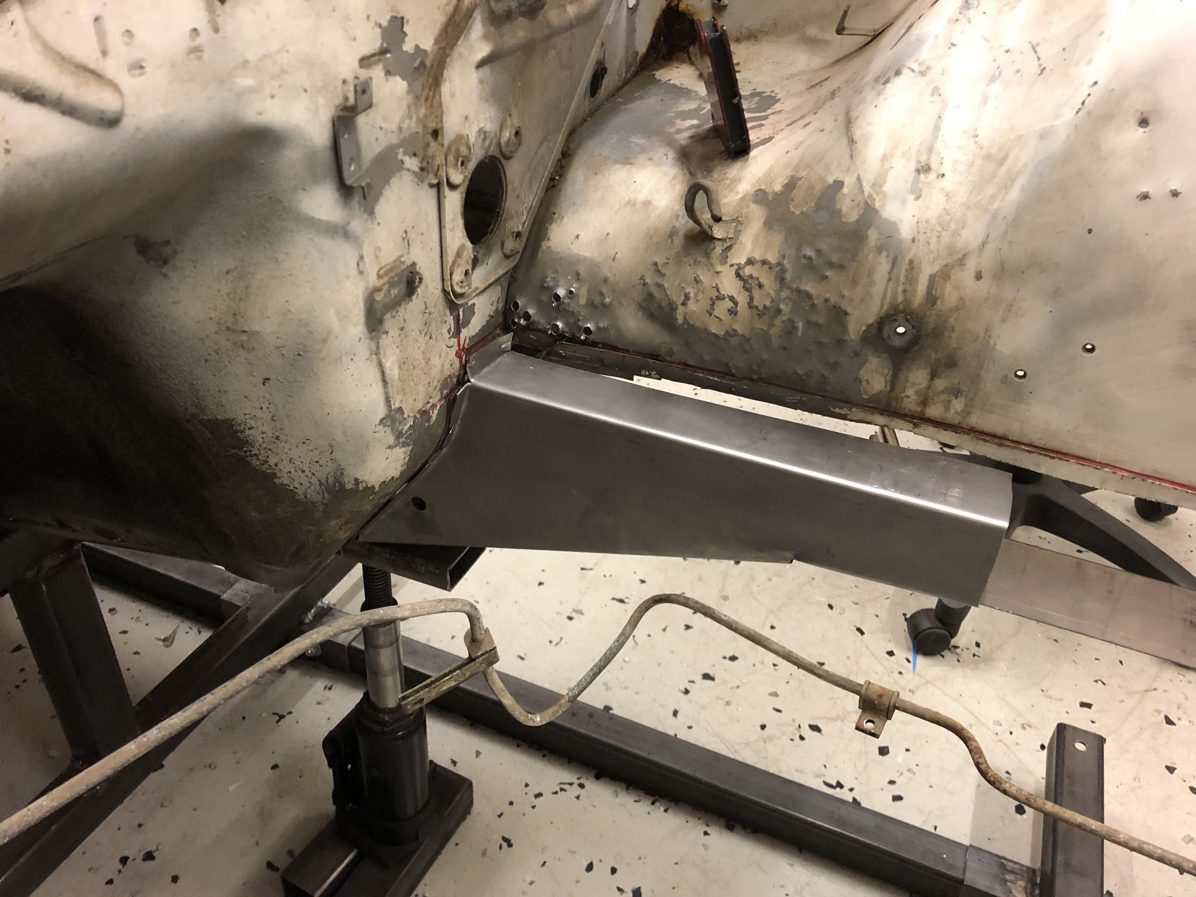
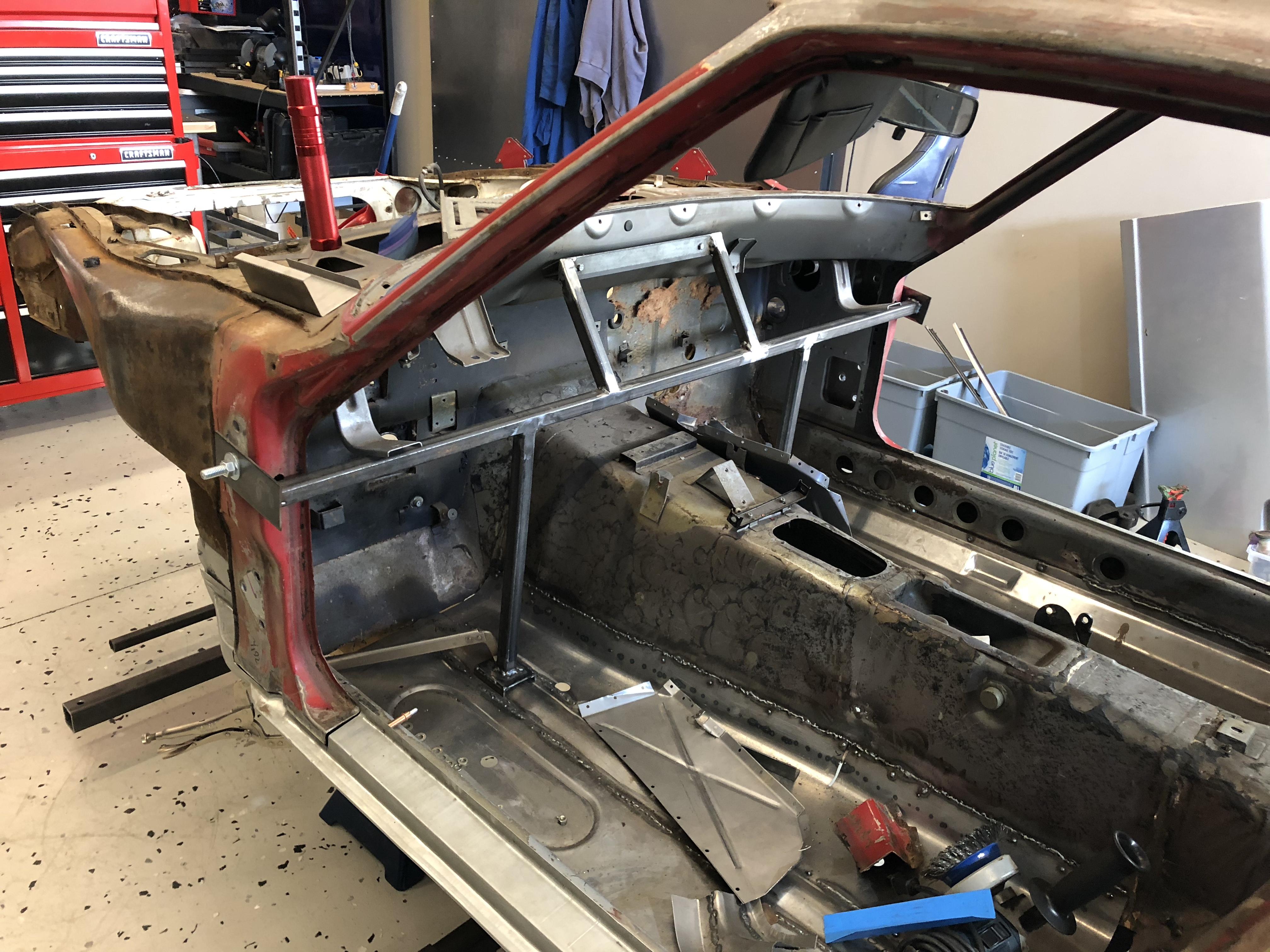
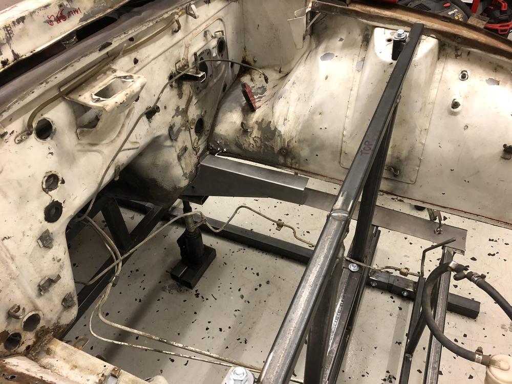
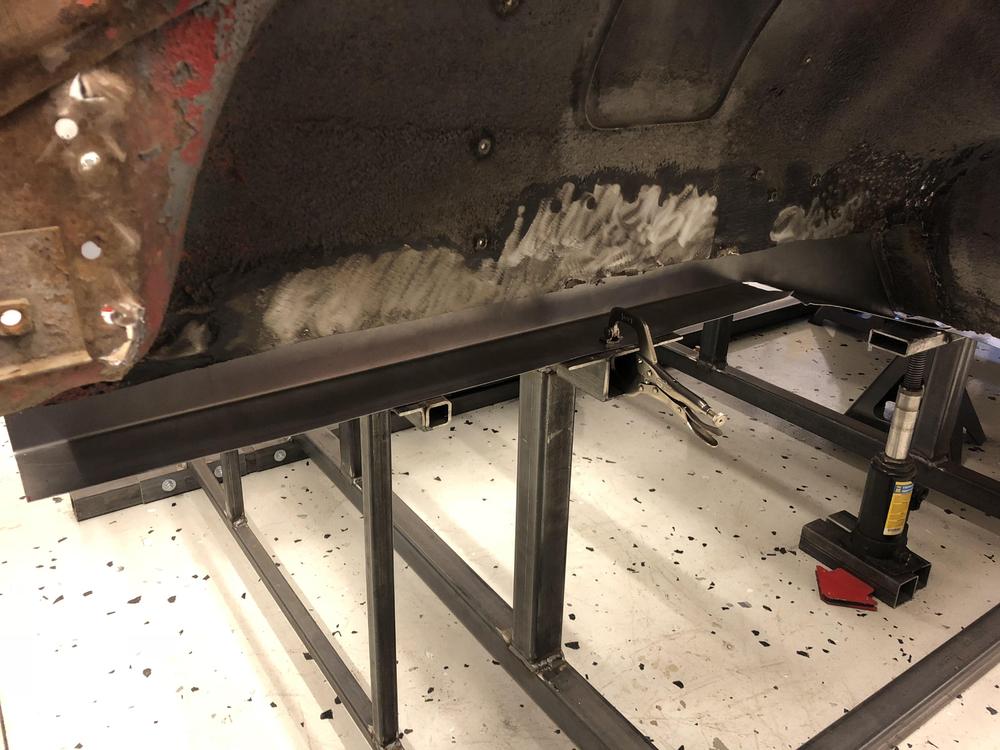
Sure. So with the front rail and the rad support out, I could push/pull the horn side to side a few mm by hand easily (except for the strut support holding it it place). If it was out of alignment, I could easily be re-aligned. The legs of the jig are bolted to the car, and to the long longitudinal rails. So the jig gets assembled / dissambled under the car while the car is on jacks. The floor is epoxy installed by the previous owner. It is slowly being destroyed by all the metal work ....
-
-
- no. I did the floors years ago, and then the car just sat for a couple of years.... The jig was built to factory dimensions, not to this car. I posted about the build in my other thread “240z gets jiggy”. (Can you link to another thread here? Not sure how to do it). Anyways, the jig supports the car at all the factory drivetrain and suspension points and under the floor rails. If the car is out of alignment you can pull it pack in for sure. The front is partially supported by the strut tower. It would be almost entirely if I had cut out both rails at the same time. The next support point is the transmission mount. its very rigid. Car did not budge when I cut the rail.
-
-
-
-
-
Haha - thanks Mark! Now that I am rolling, I am going to try to FINISH one LOL!
-
Thanks! The old 240 was actually surprisingly straight given how rusty she is. It was actually quite a nice car once. Unfortunately when the owner passed away the car was left sitting in tall grass so ... ???
-
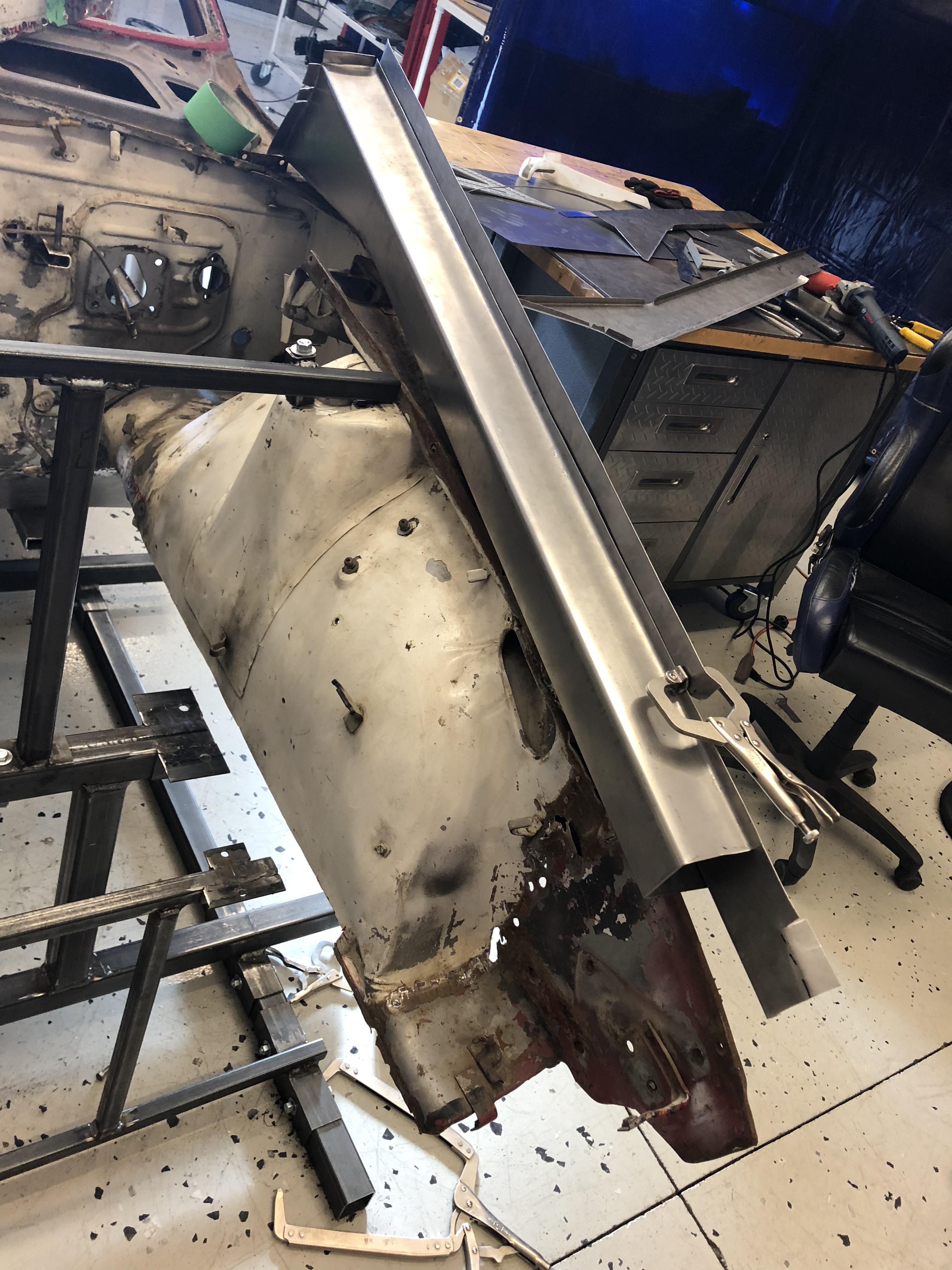
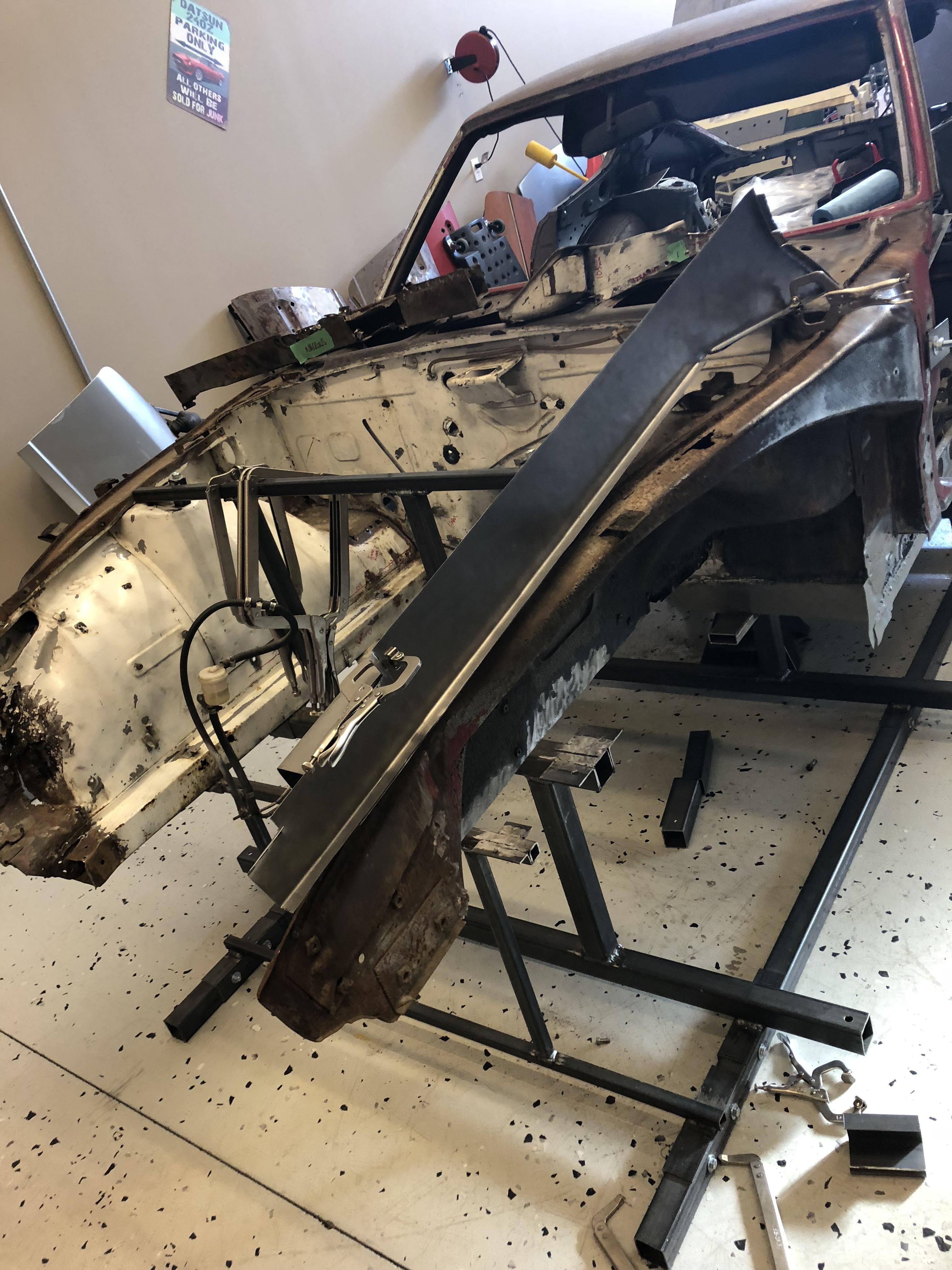
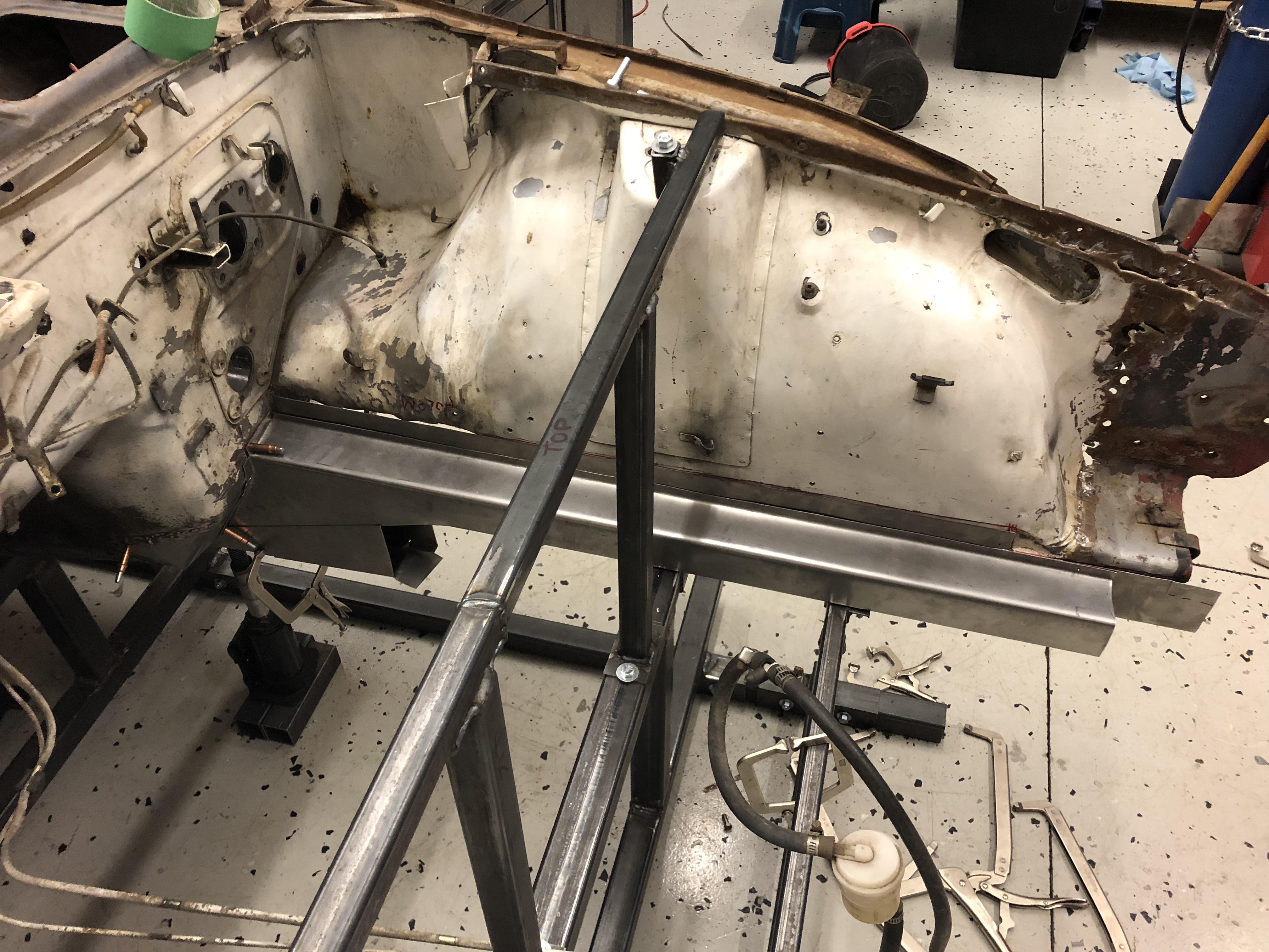
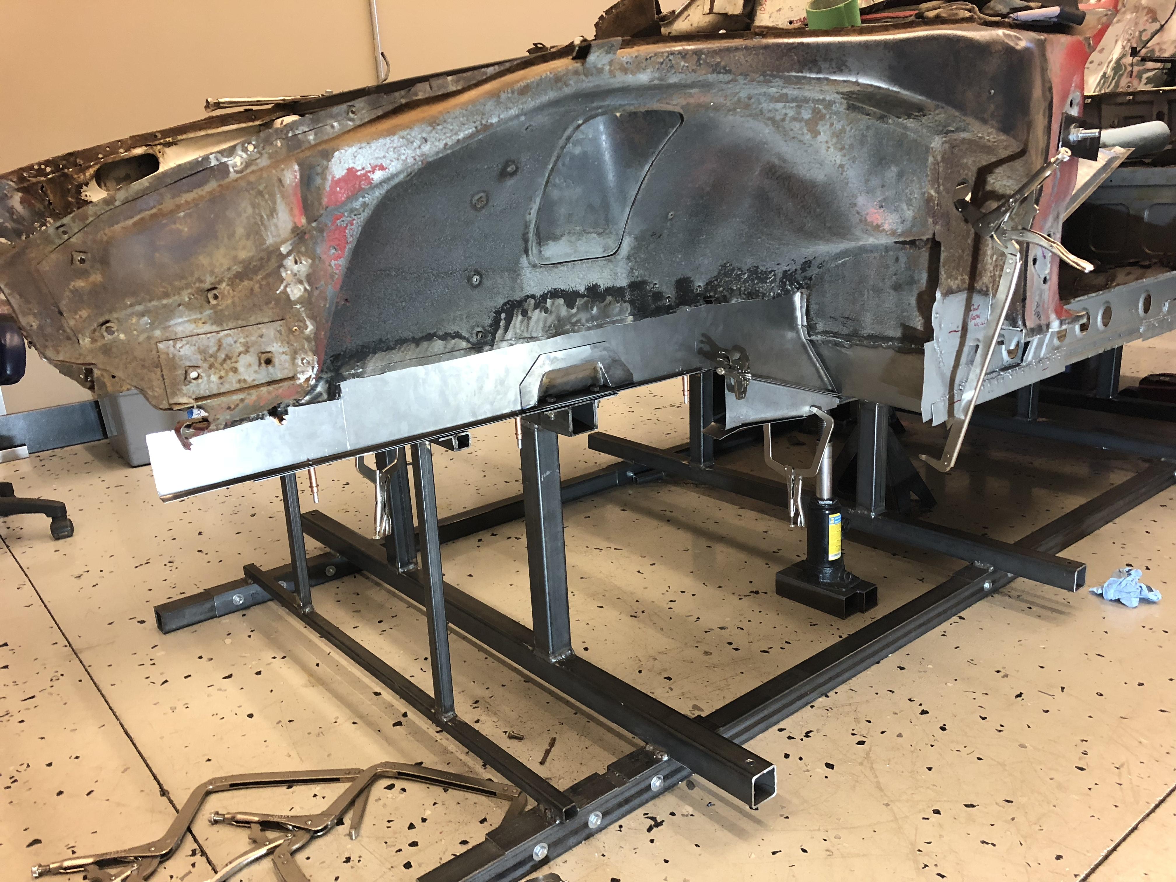
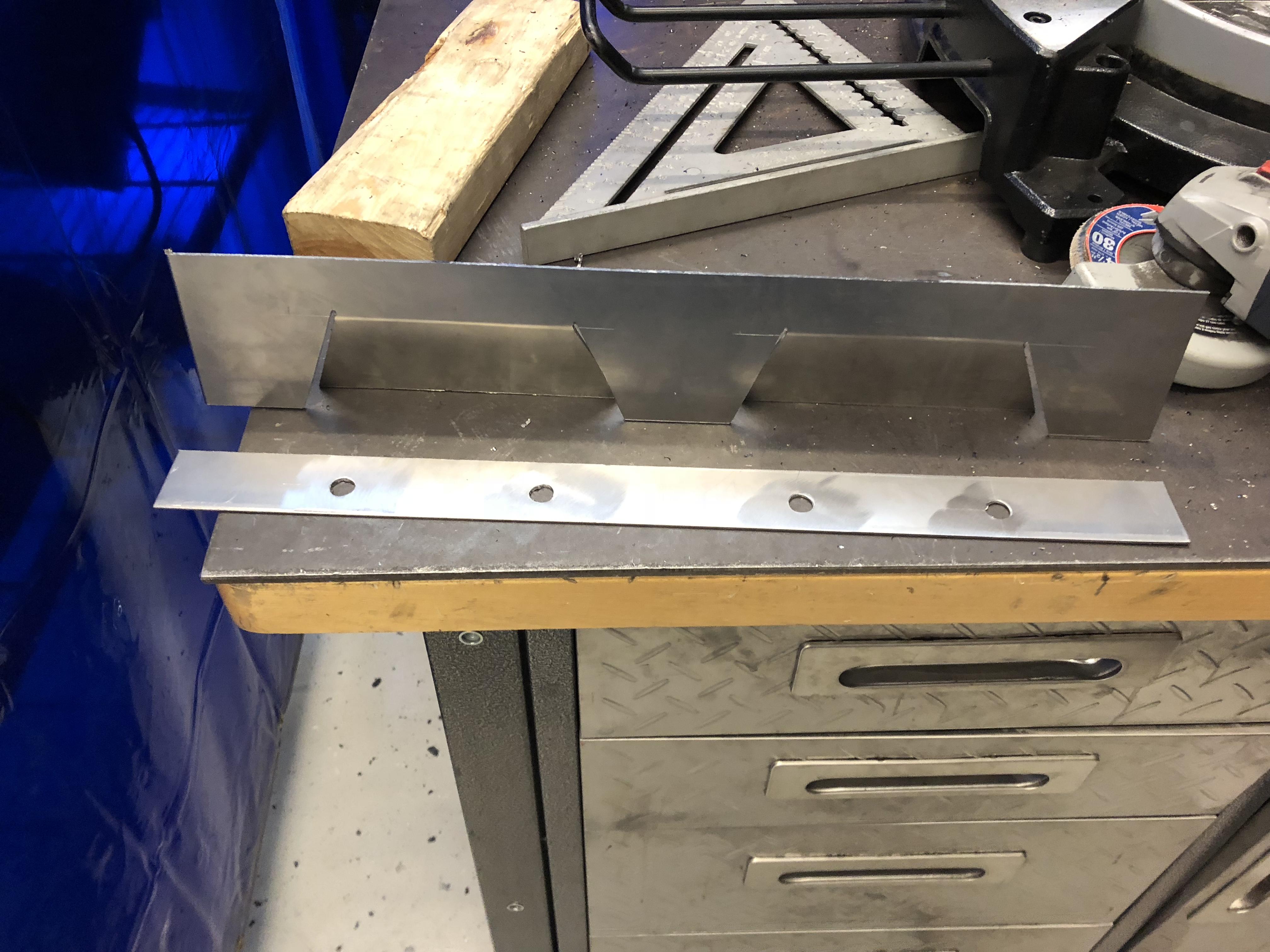
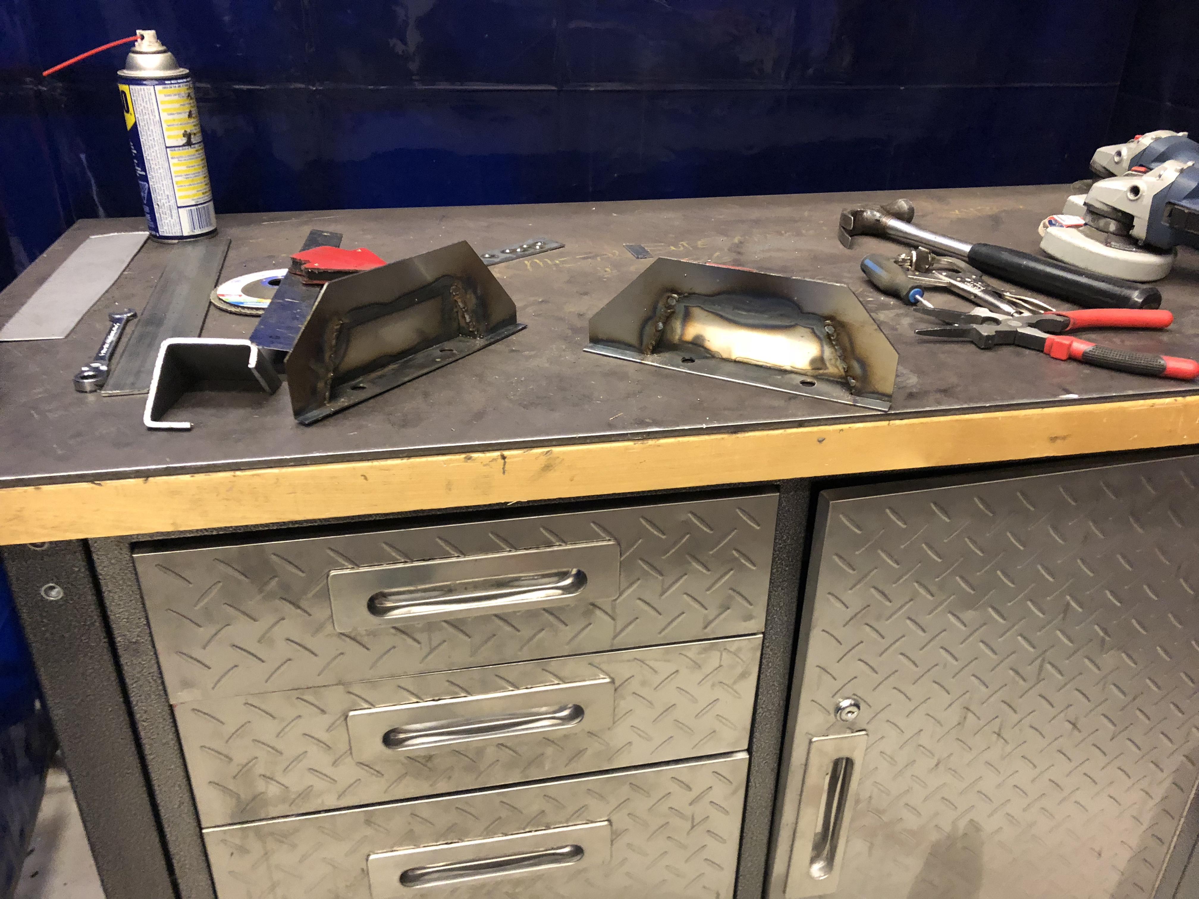
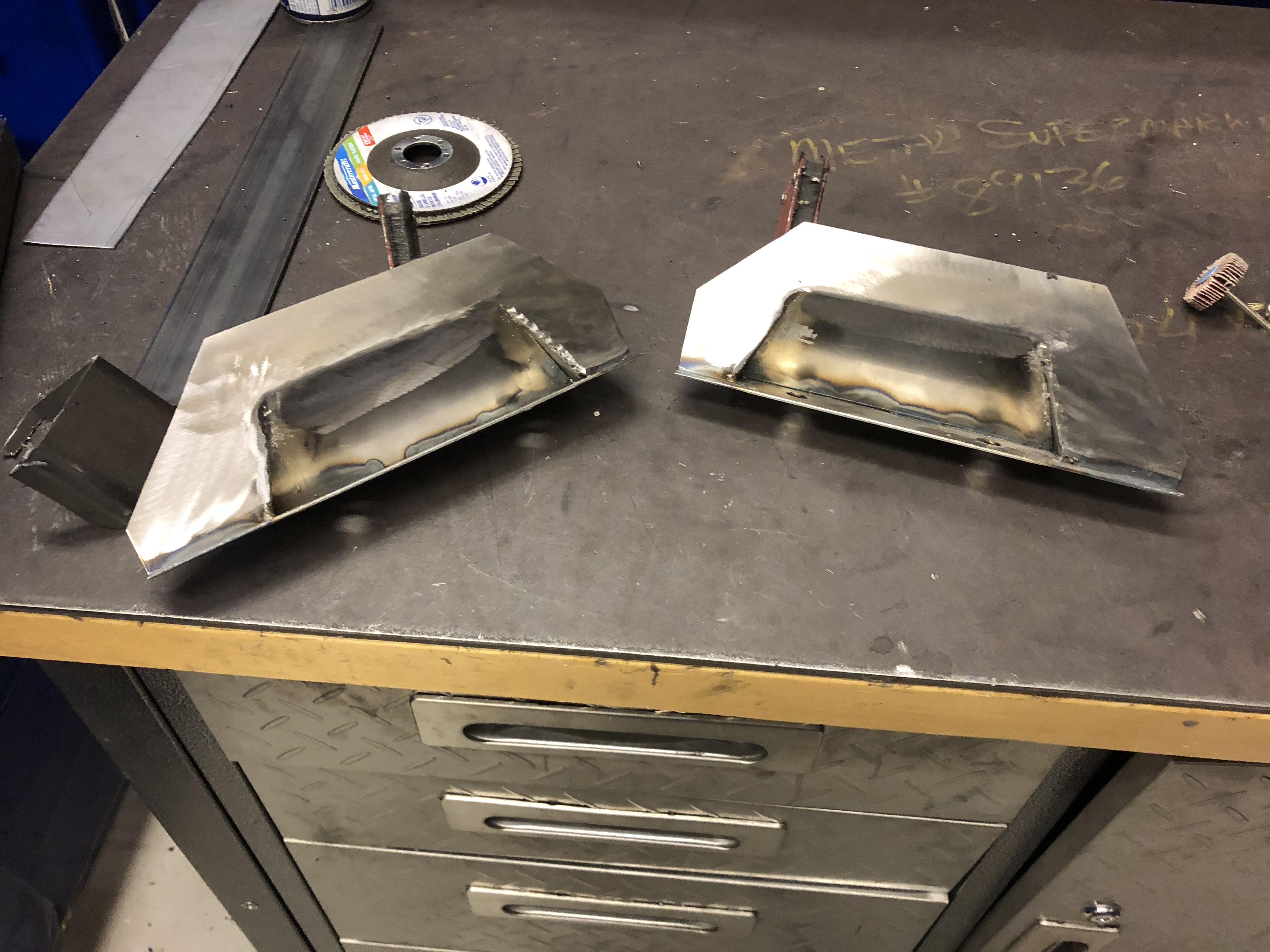
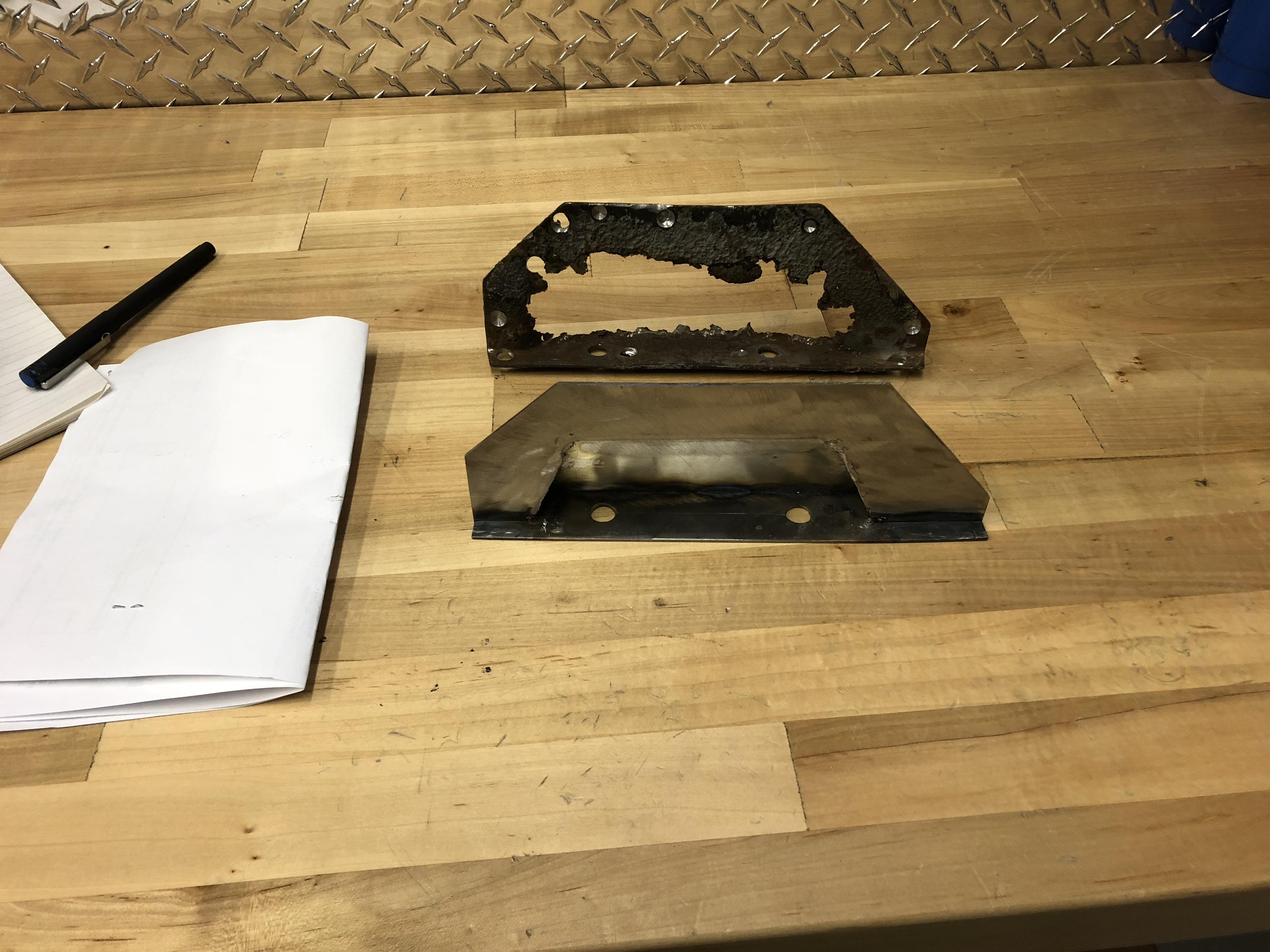
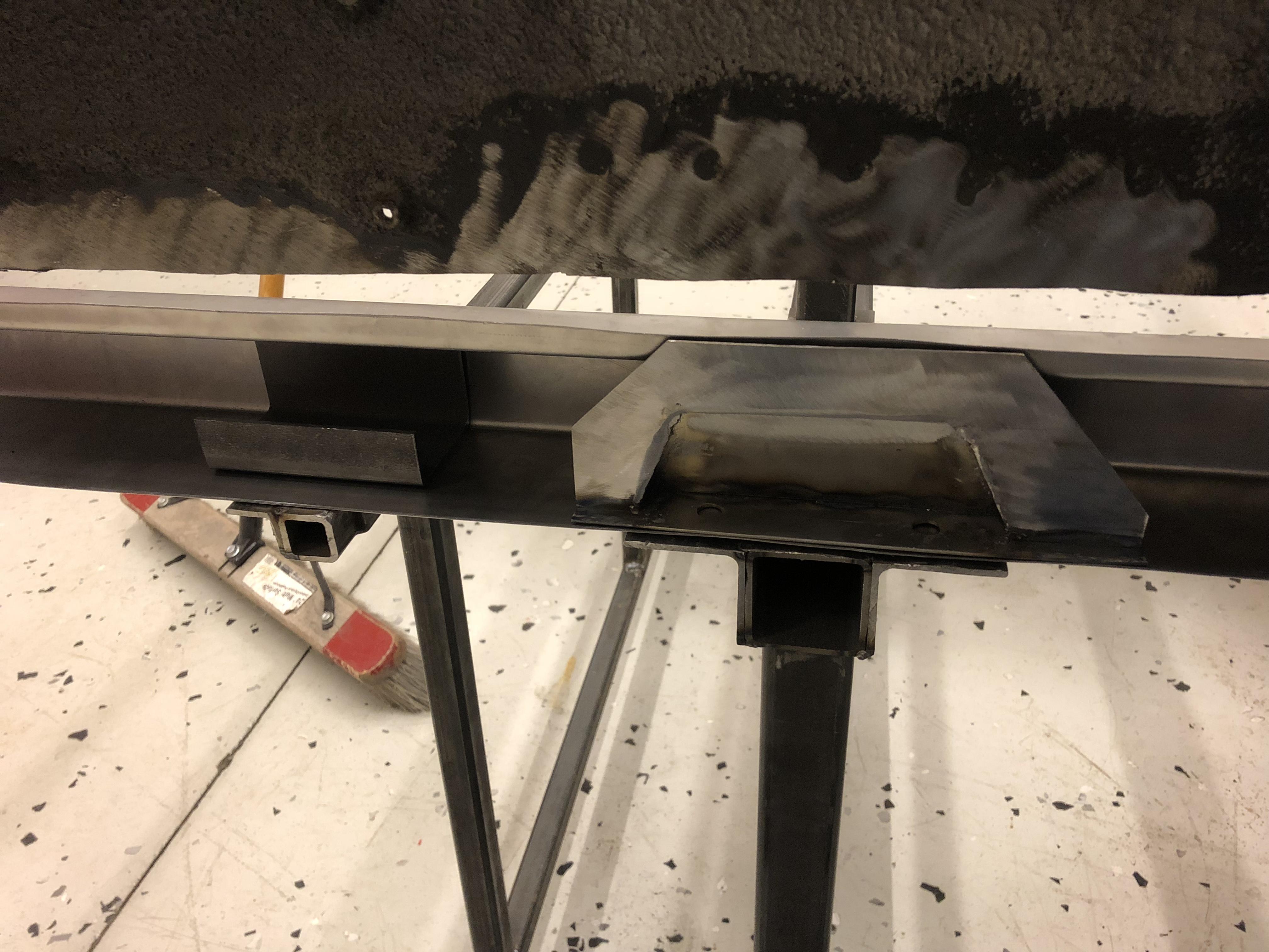
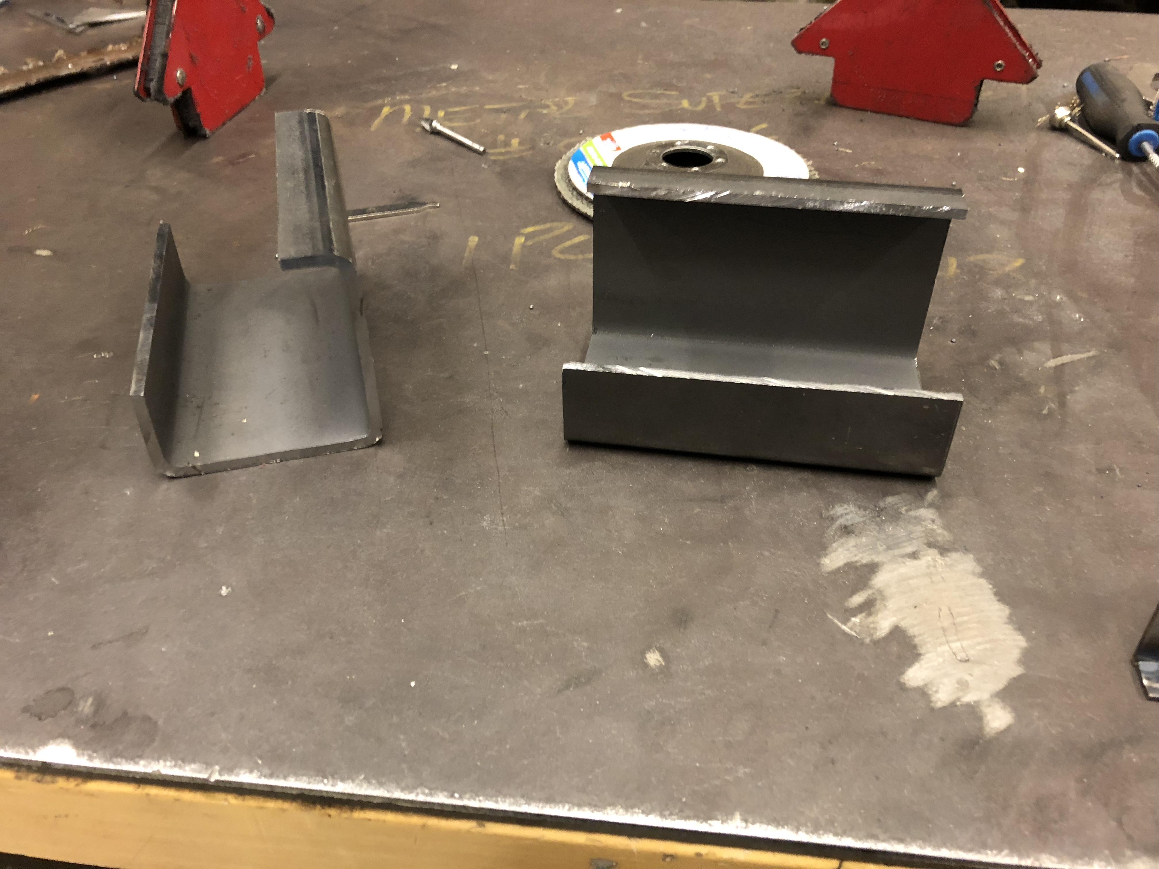
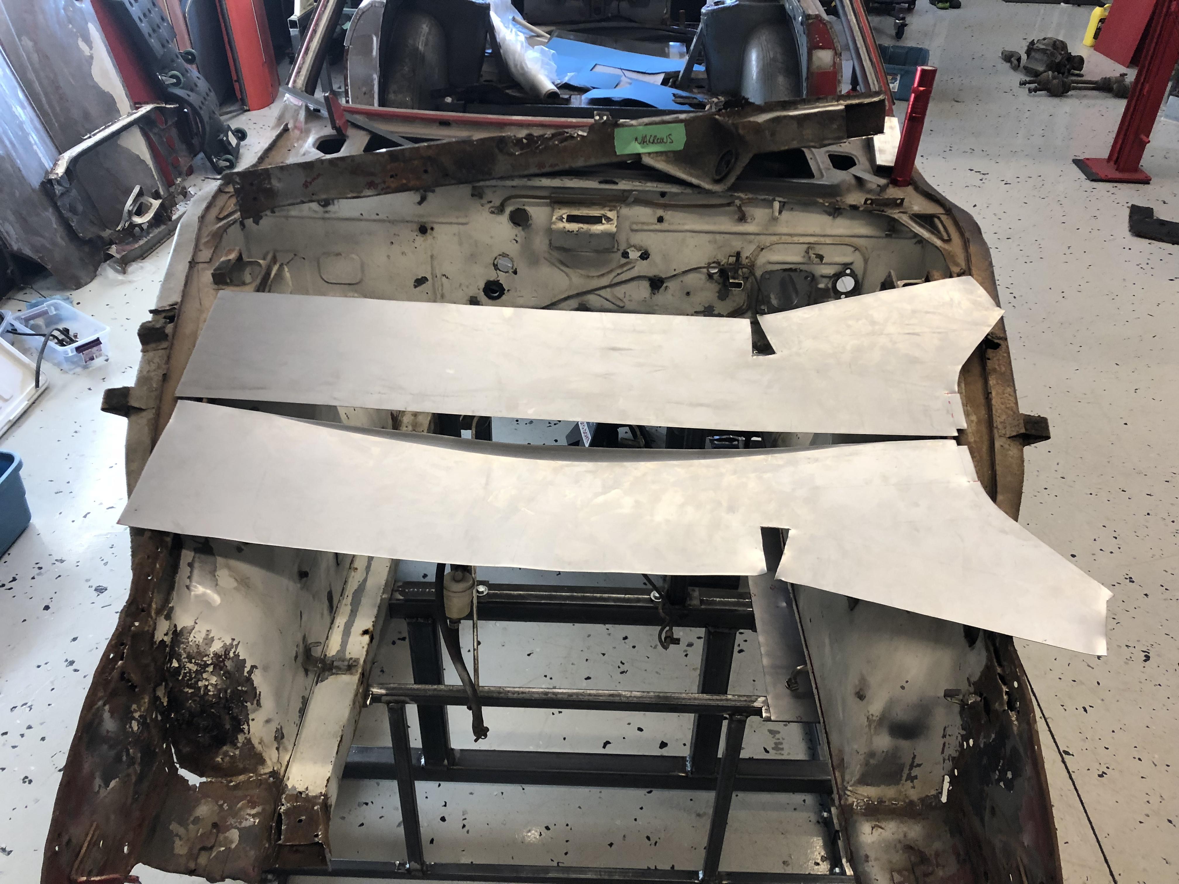
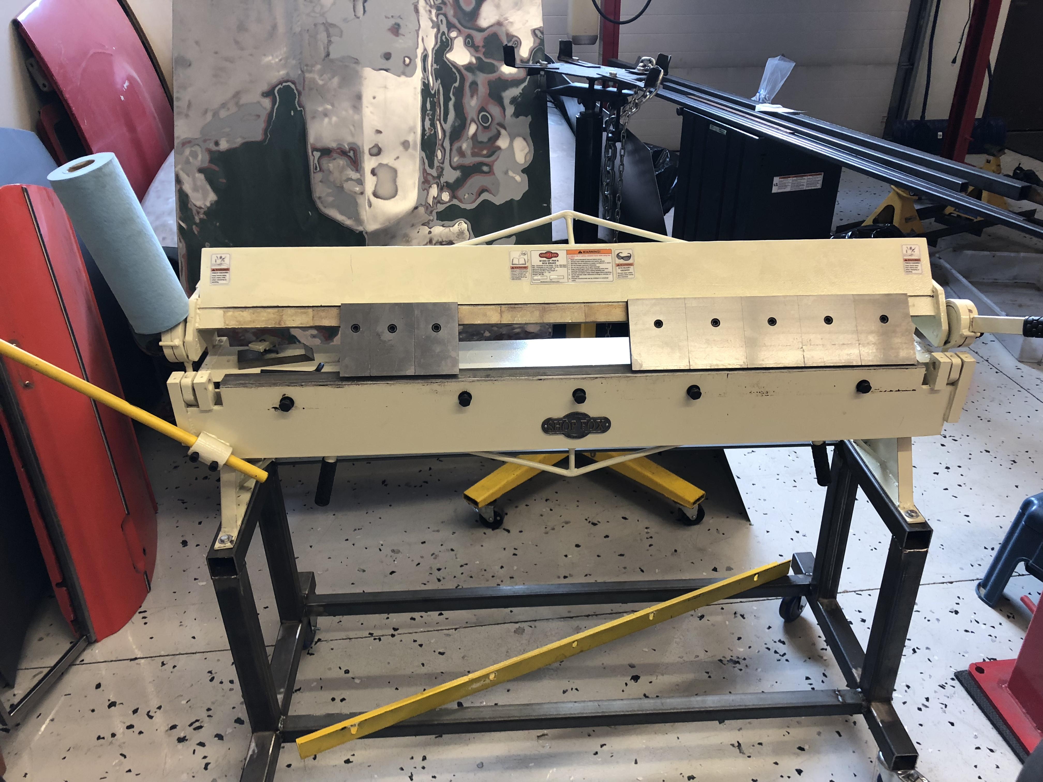
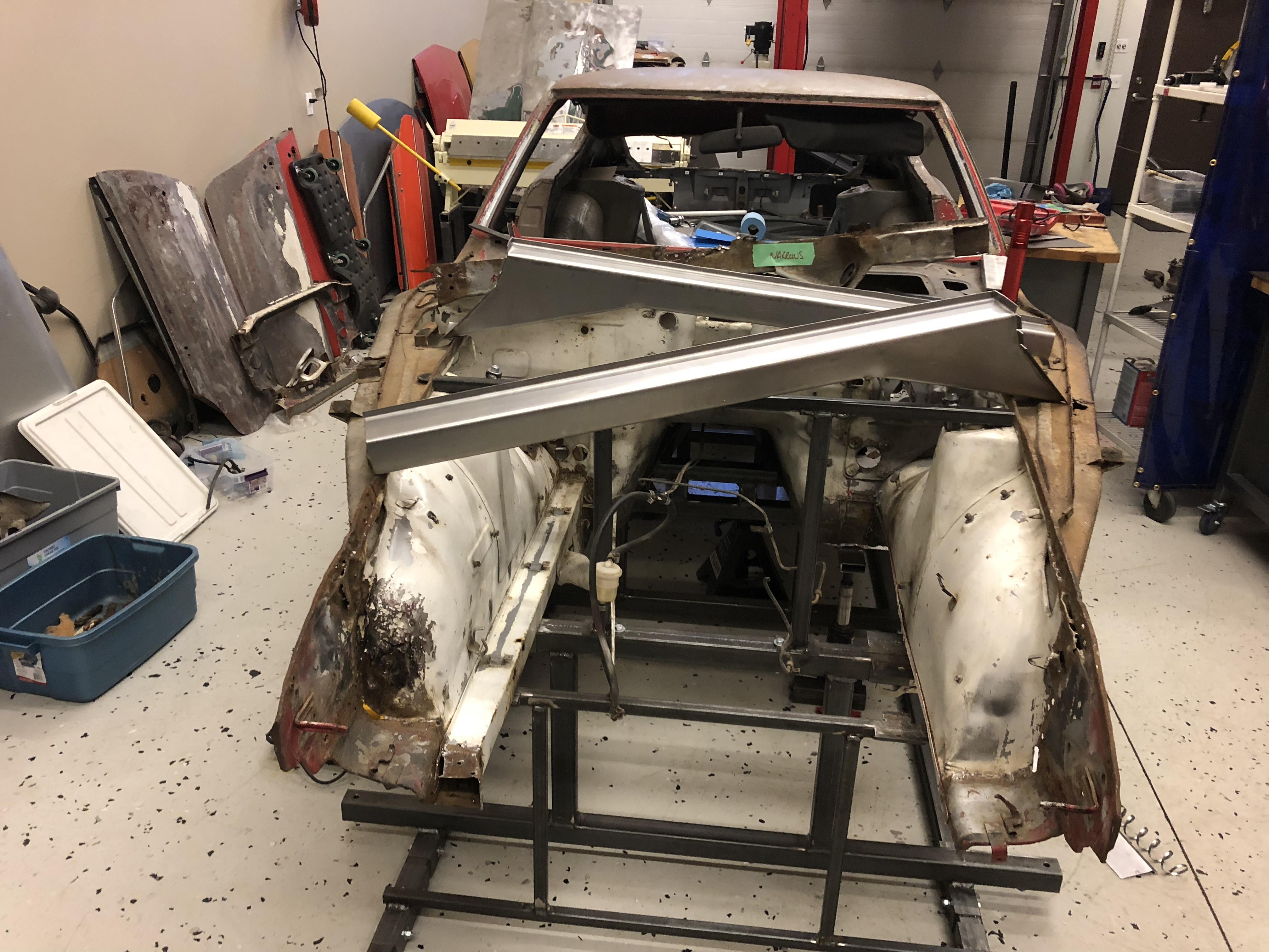
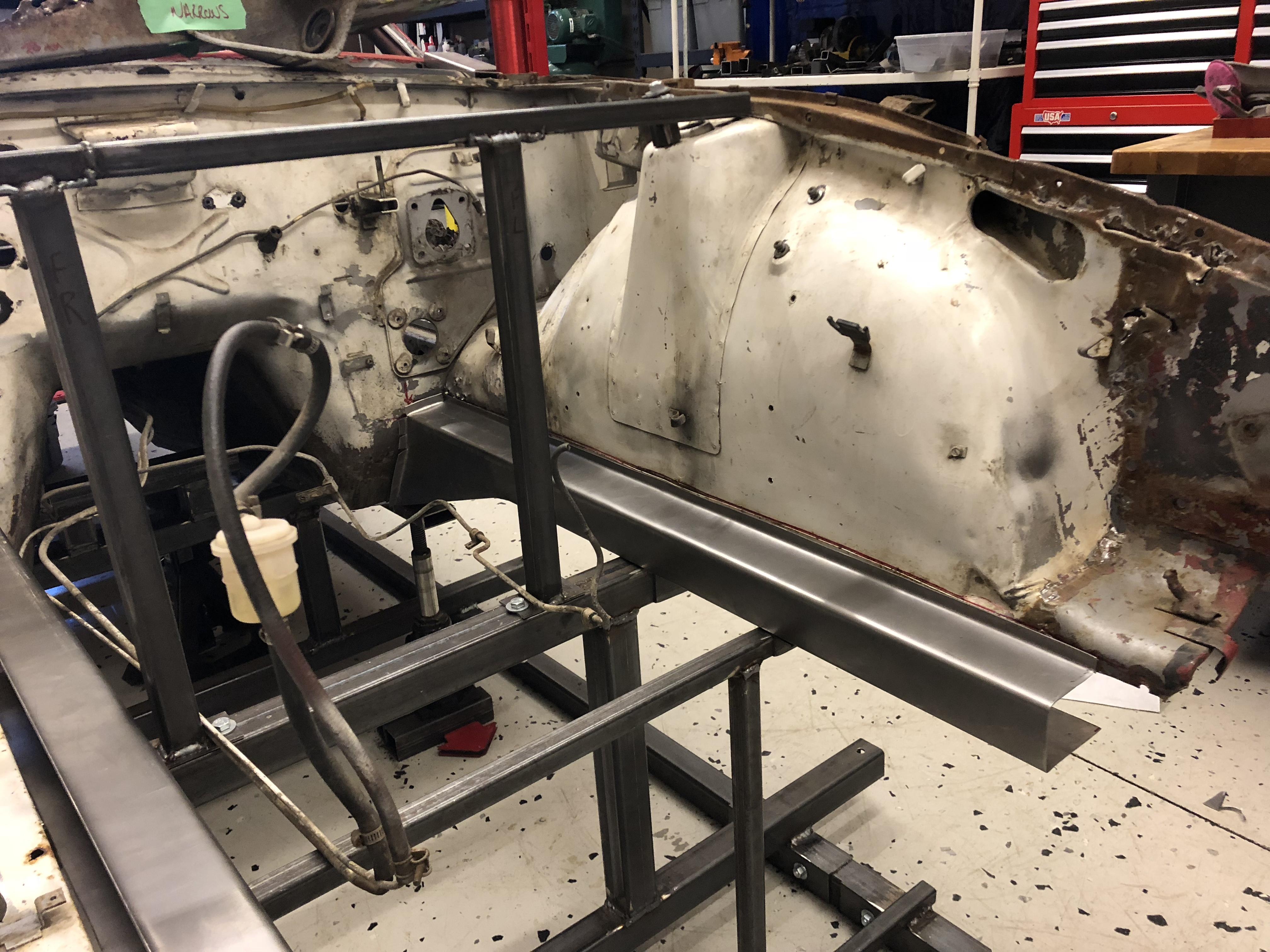
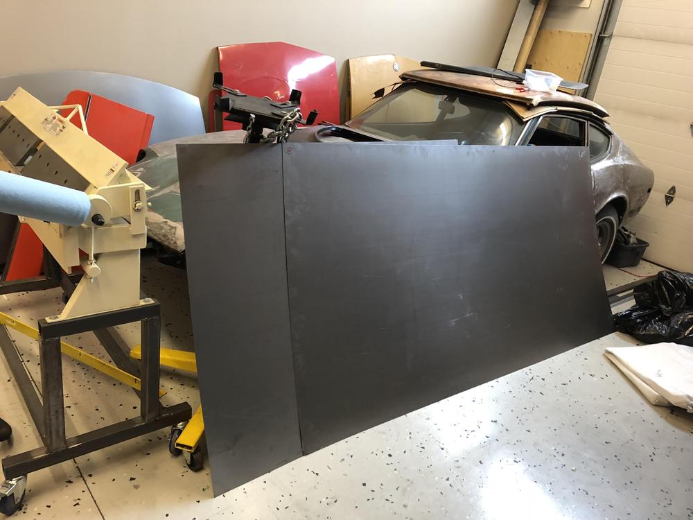
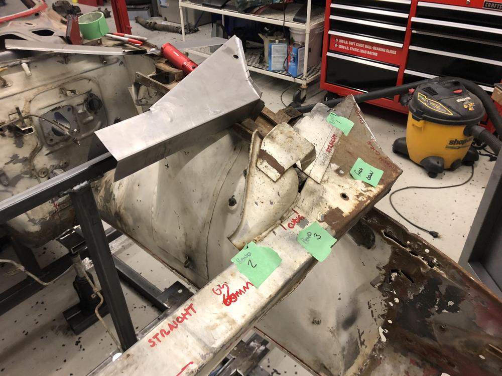
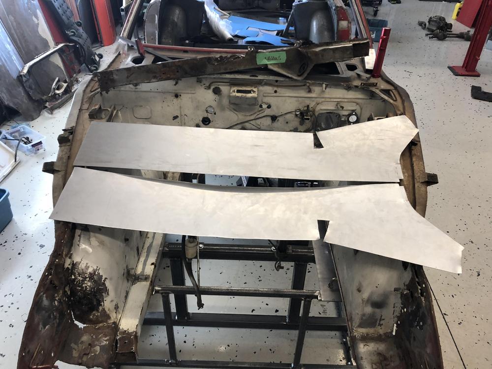
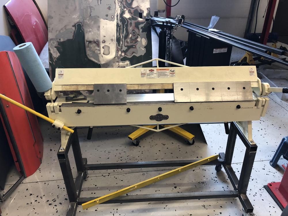
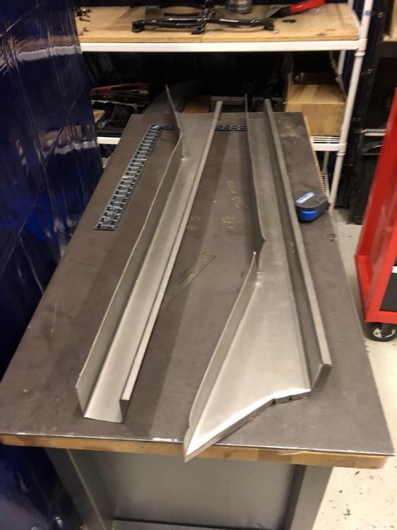
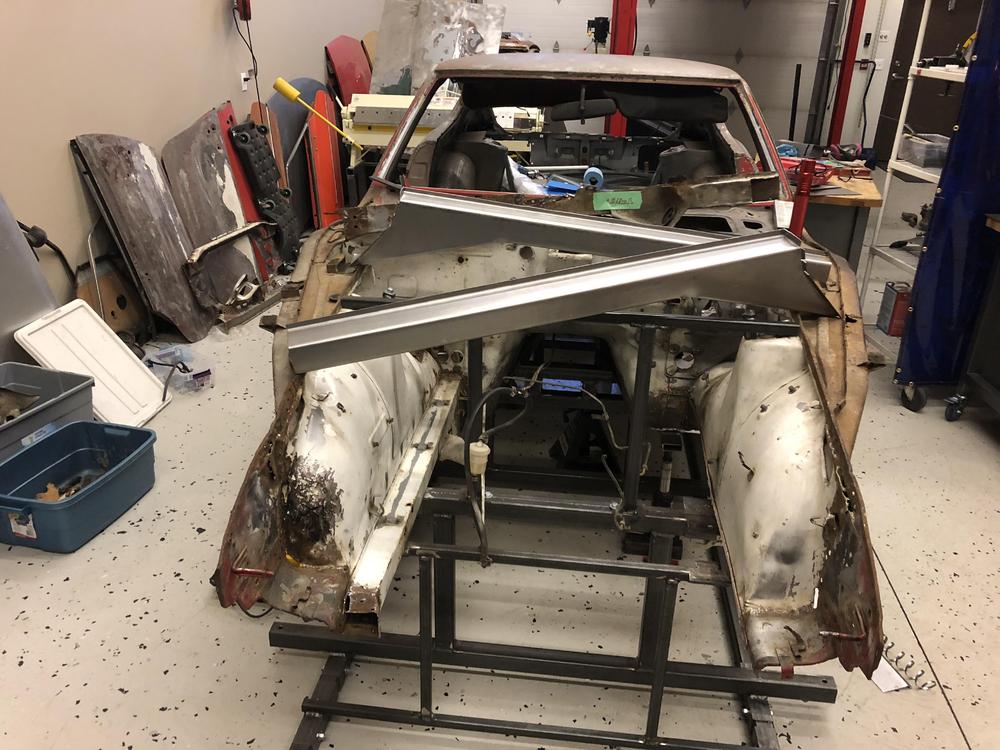
So I decided to fab up some new front rails for the Z.. What is the worst that can happen, right? (Answer: waste some time, buy a proper set from a vendor). So why not? Step 1 ? Step 2 - Pretty much committed now .... Step 3 - make a pattern and a cheap test piece from some leftover 20 ga Step 4 - game time ...18 ga Step 5 - bend them up.... This was way harder than it looks. My cheapo metal brake was at capacity, and several teeth had to be removed, inserted and realigned in order to make all the bends. But it seemed to work. z Step 6 - test fit Still a lot to do, (weld in the bend, all the internal bracing, new crossmember brackets, all the nuts, TC rod supports) but so far so good! And the jig is working perfectly. I should have done this years ago....


-
Thanks! I have more ambition than skill, but I am stubborn at least ?
-
I hope I fixed the pics? Still learning to drive, sorry
-
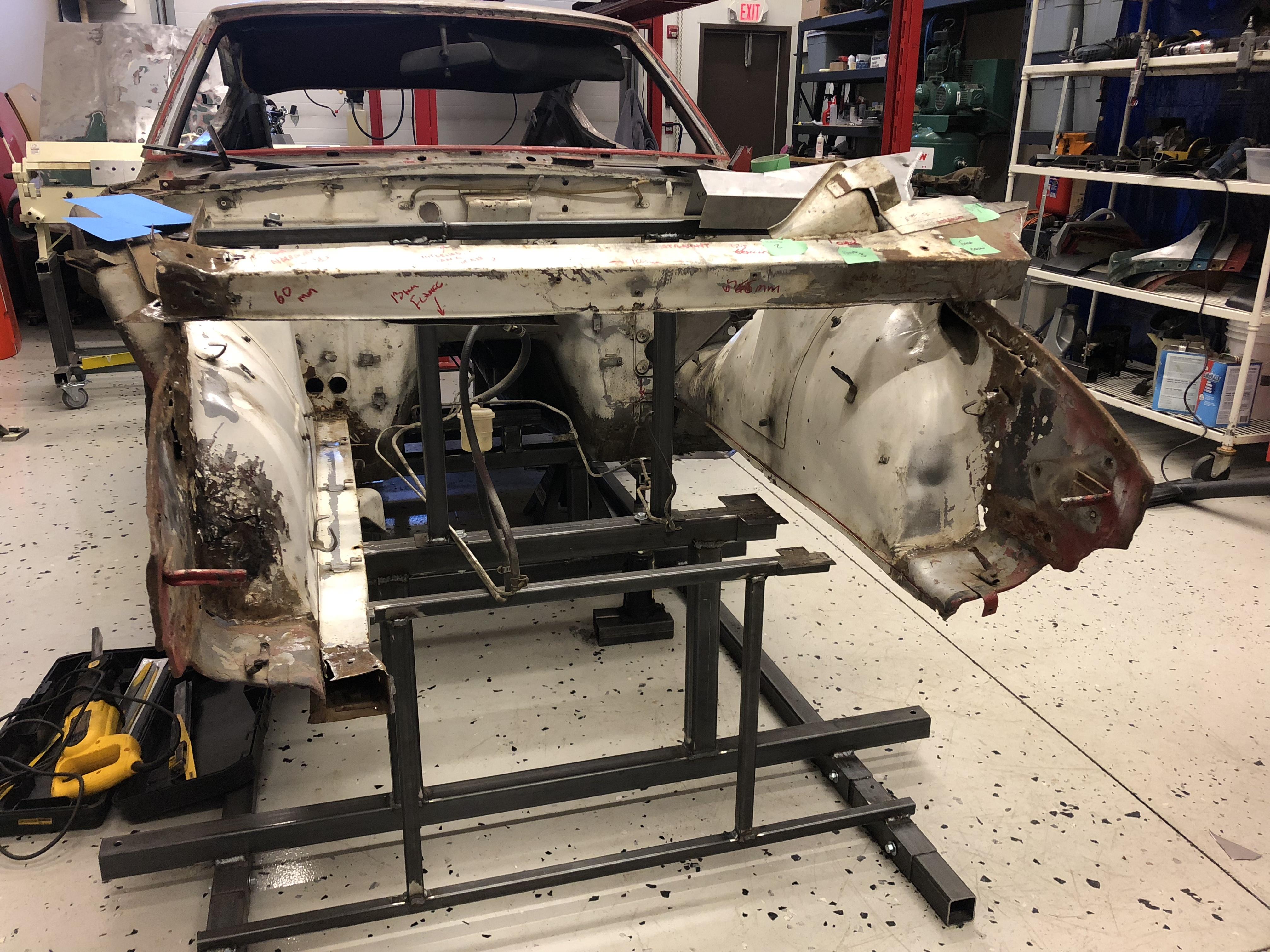
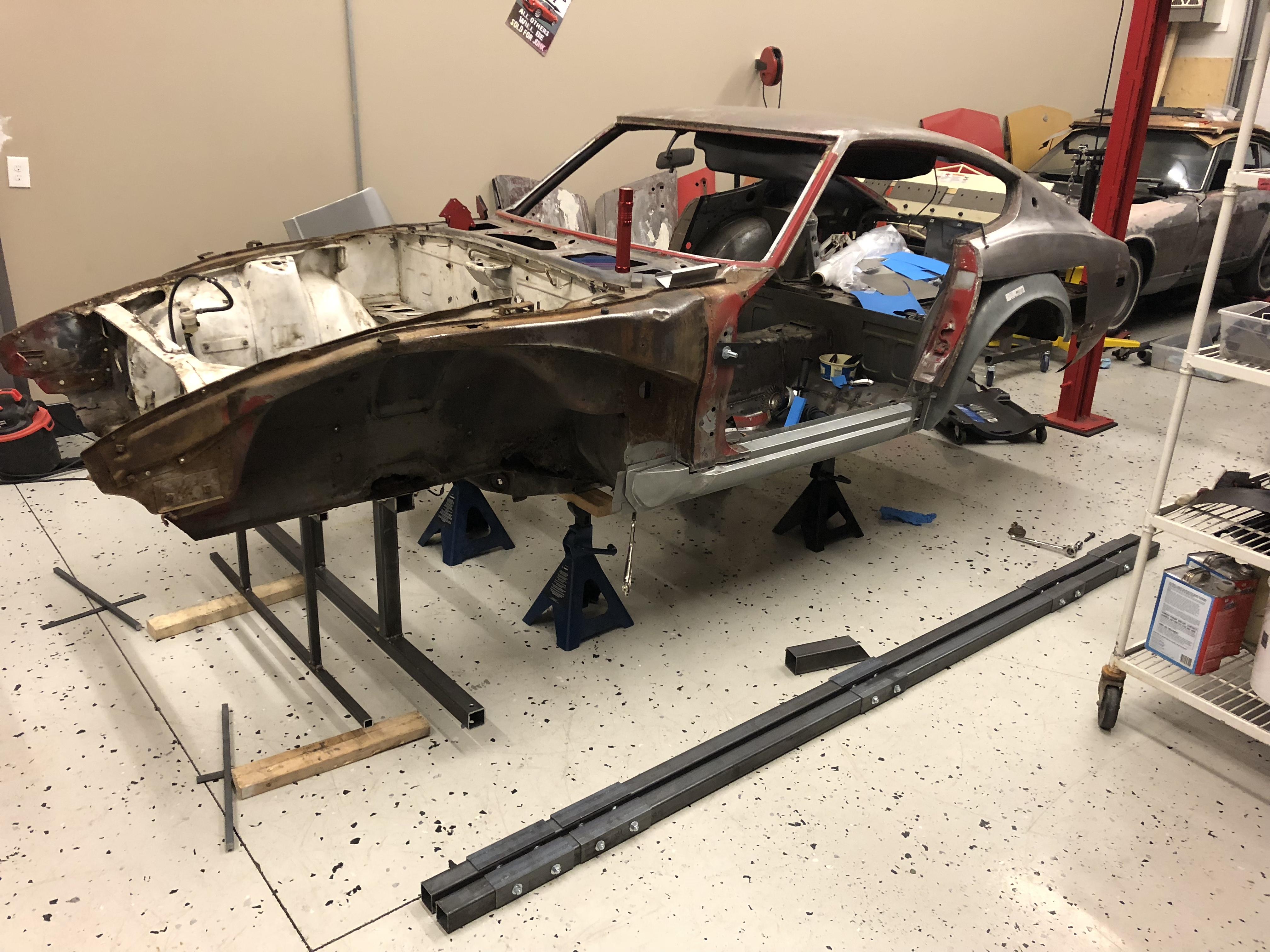
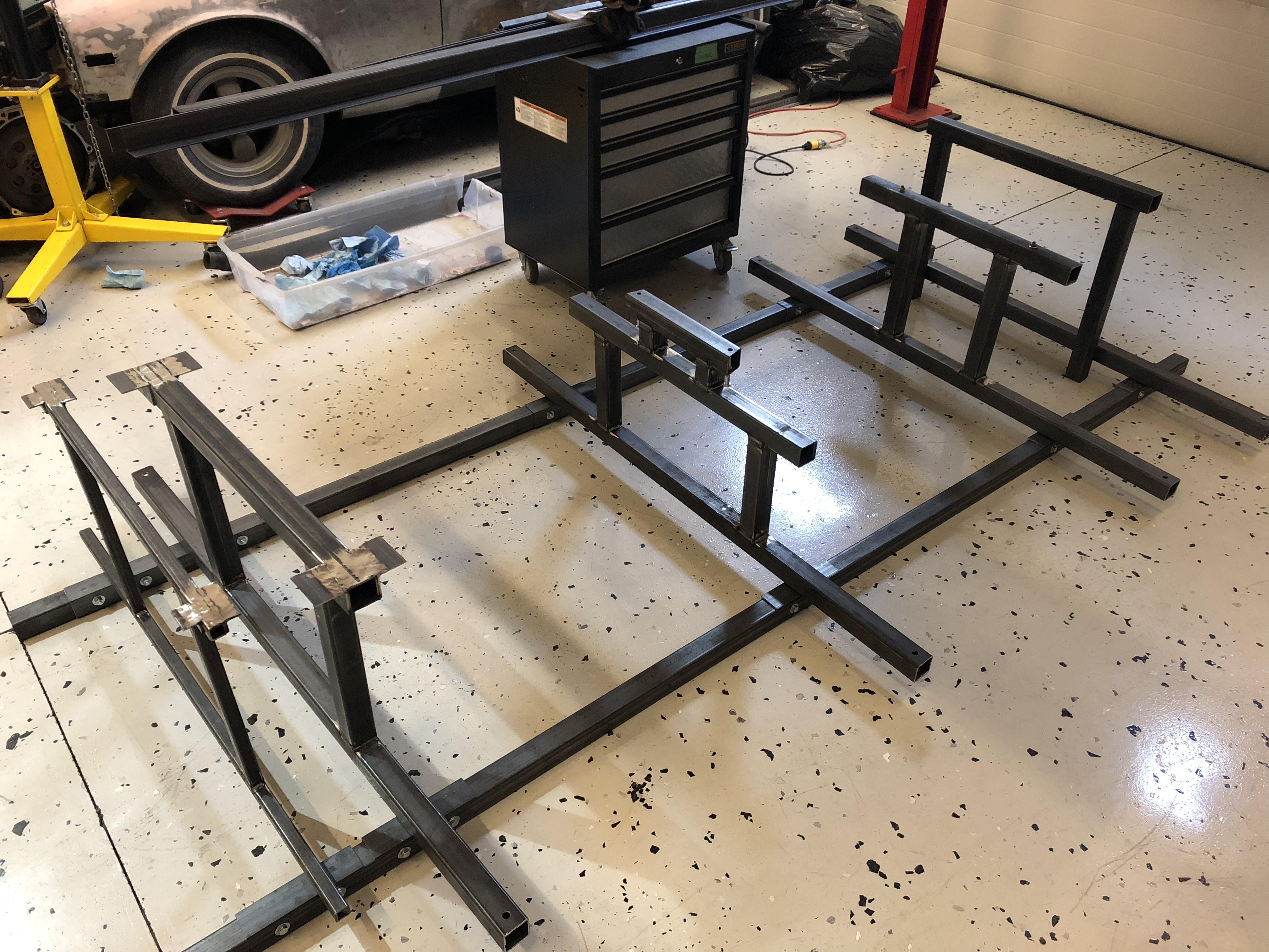
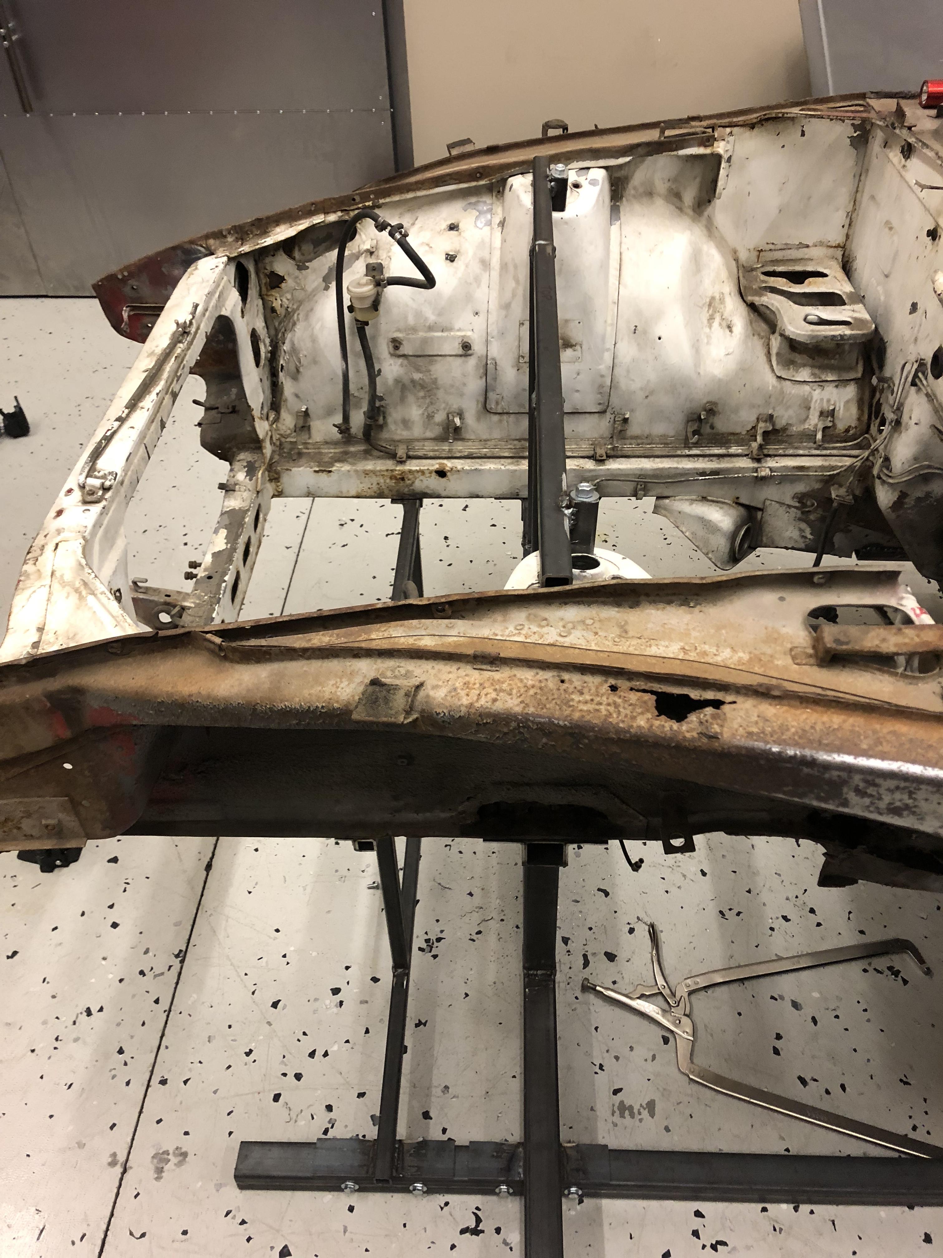
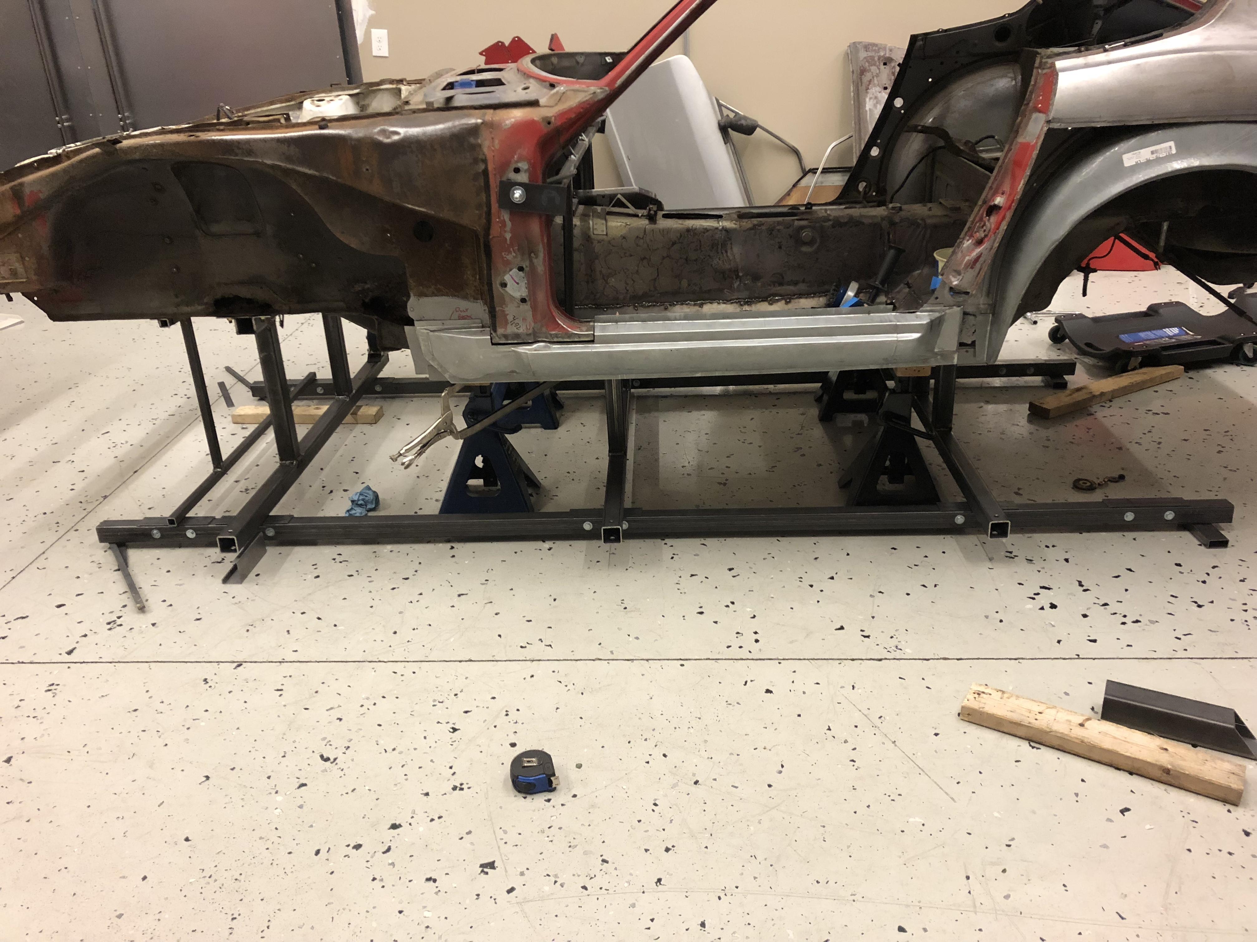
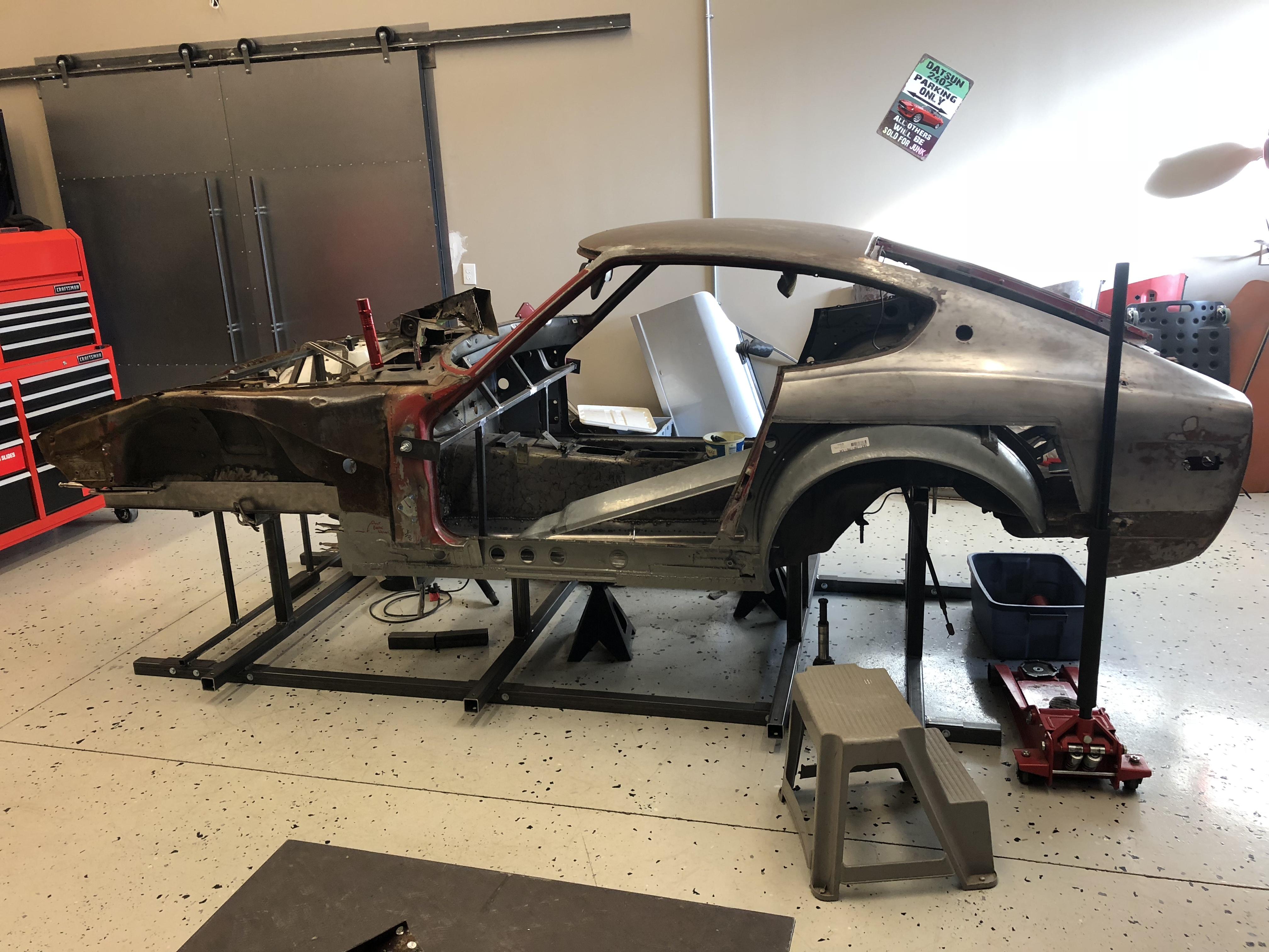
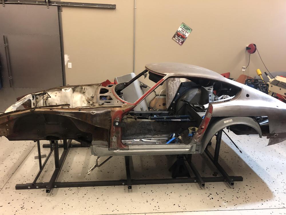
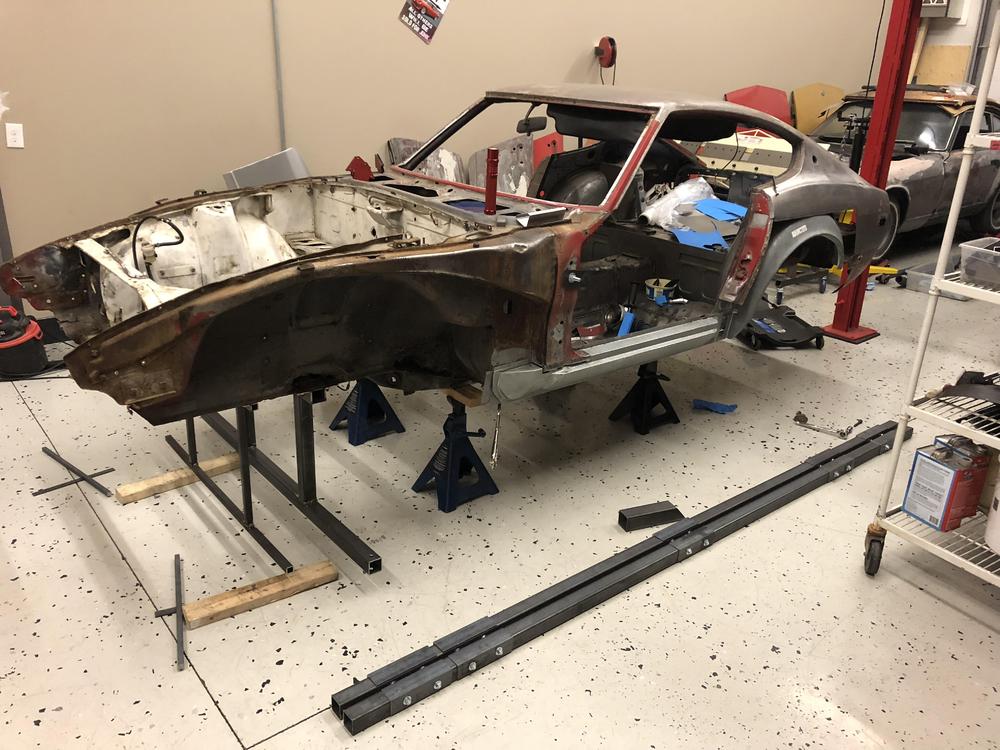
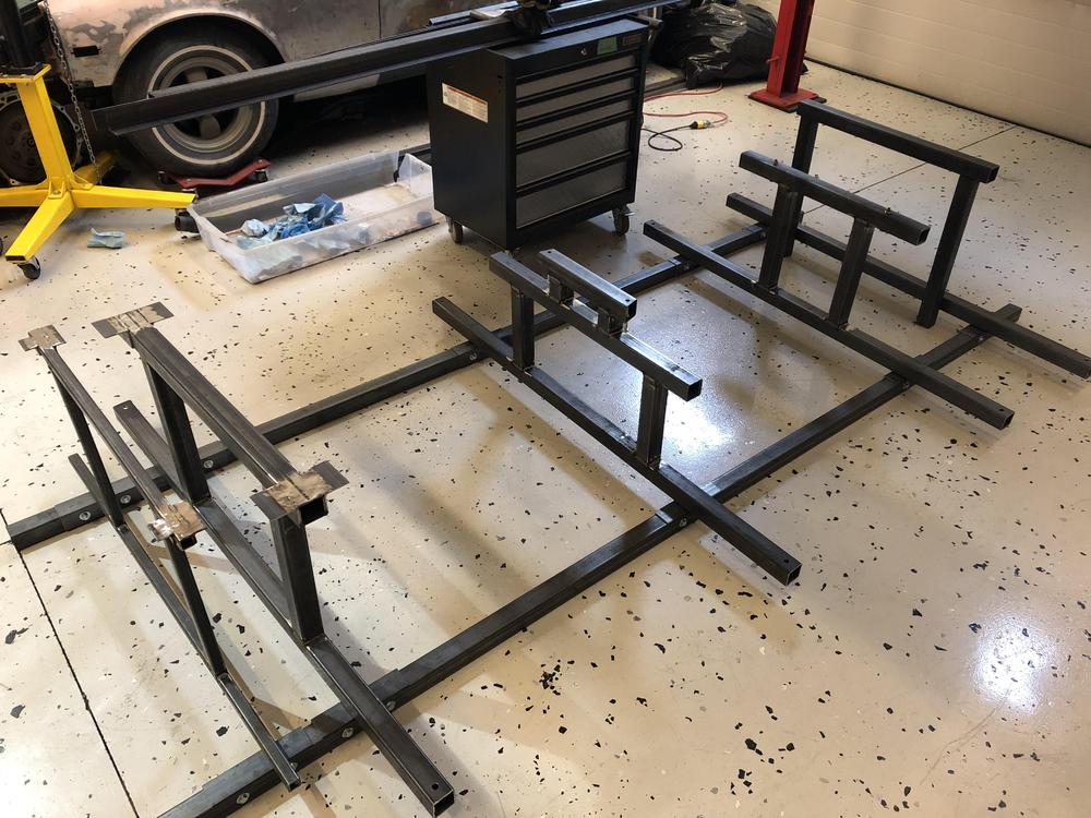
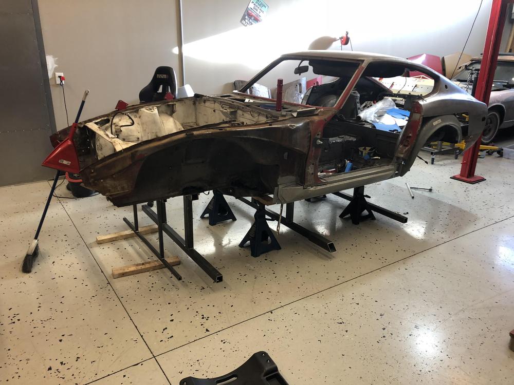
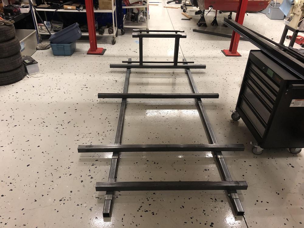
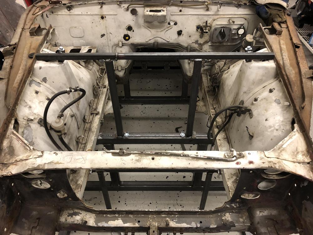
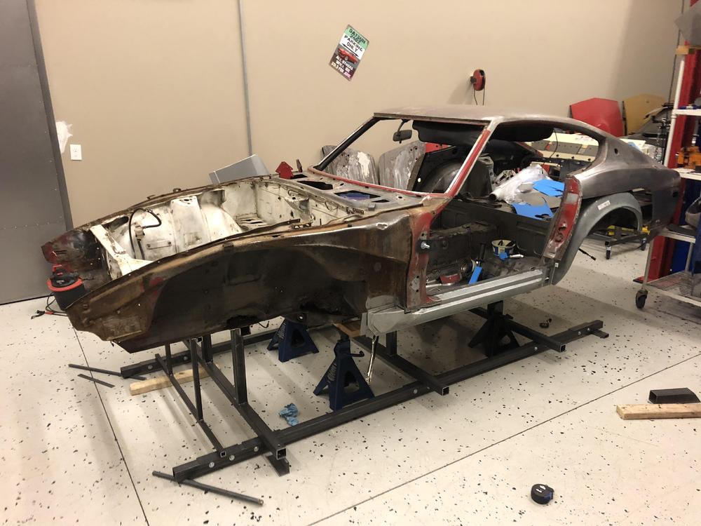
Hi Guys. My name is Kent and I am a long time lurker here. I have several 240z project cars - none completed - but lots of ambition ....but that’s a story for a whole different thread probably. I started this car a few years back and, skipping to the point, I recently realized that I needed to take a step backwards in order to go forwards. I had replaced the floors and fabricated some new floor rails, but I realized that it would be nearly impossible to replace the front rails and firewall rust without stabilizing the entire chassis. Plus the rad support was repaired poorly by a previous owner at some point. Rotisserie was out of the question - way too much rust... Here she is on the completed jig .... a The jig was made from 2 x 2 x 1/8 tubing. It supports the chassis at stock suspension and drivetrain points - front swaybar, front crossmember, trans tunnel, and both side of the rear differential mounting point. I also added a support for the front strut tower, and across the door openings as I will be cutting out a lot of the firewall and the front rails. All the dimensions are available in the FSM. It is bolted (not welded) to the chassis. The whole structure is very rigid and I think that the firewall and frame rail replacement is going to zip right along. Here’s how she came together, in pictures .... hopefully this inspires someone else to get back on the horse. Cheers! e ;


-
NO - this is Kent. I lurk here sometimes but never post ....
-
It was pretty scary in person, and I don’t mind the odd dream project