KenFirch
 Subscriber
-
Posts
265 -
Joined
-
Last visited
-
Days Won
5
Content Type
Profiles
Knowledge Base
Zcar Wiki
Forums
Gallery
Events
Downloads
Store
Blogs
Collections
Classifieds
Everything posted by KenFirch
-
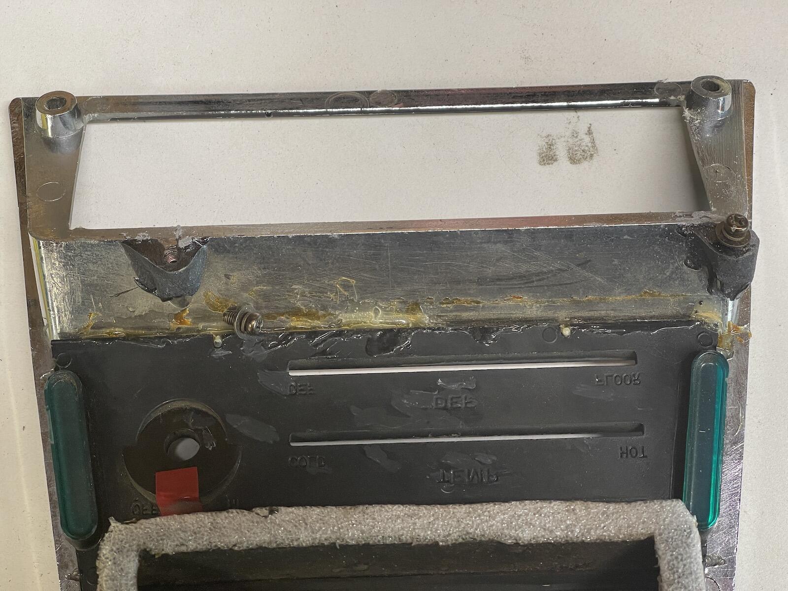
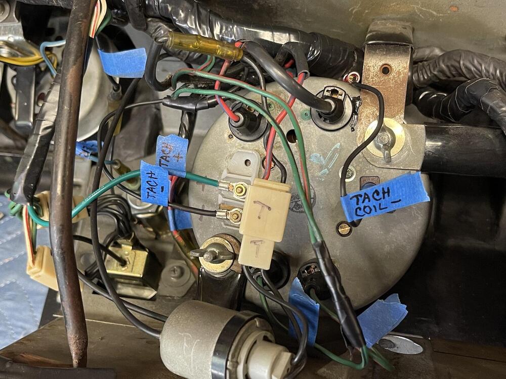
Okay, finished tracing out the tach wires. The feed was correct, goes through black/gray to coil negative. The plastic power connector was removed in the past, so the + to tach was wrong. I added the green + wire, spliced into green to hazard switch. If I need to add a resistor for the tach feed, I'll deal with that later if needed. Took all the heater control cables off and oiled them up. The little threaded brass inserts that hold the lever panel to the back of the center console had broken off, so I JB welded them back in place. Hopefully they will hold.
-
Ah, thanks for that. Fiber optic in the 70's, who would have thunk!
-
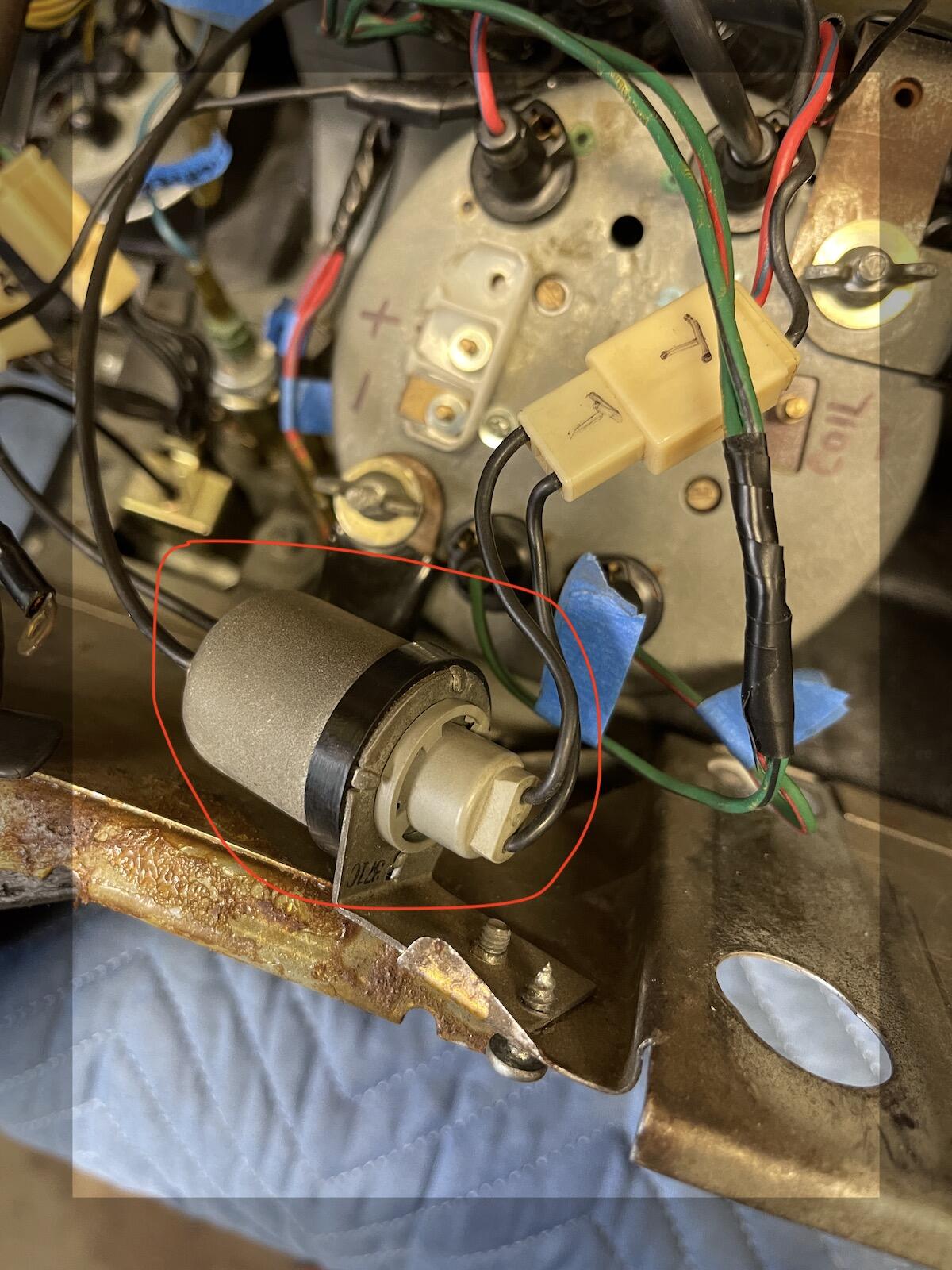
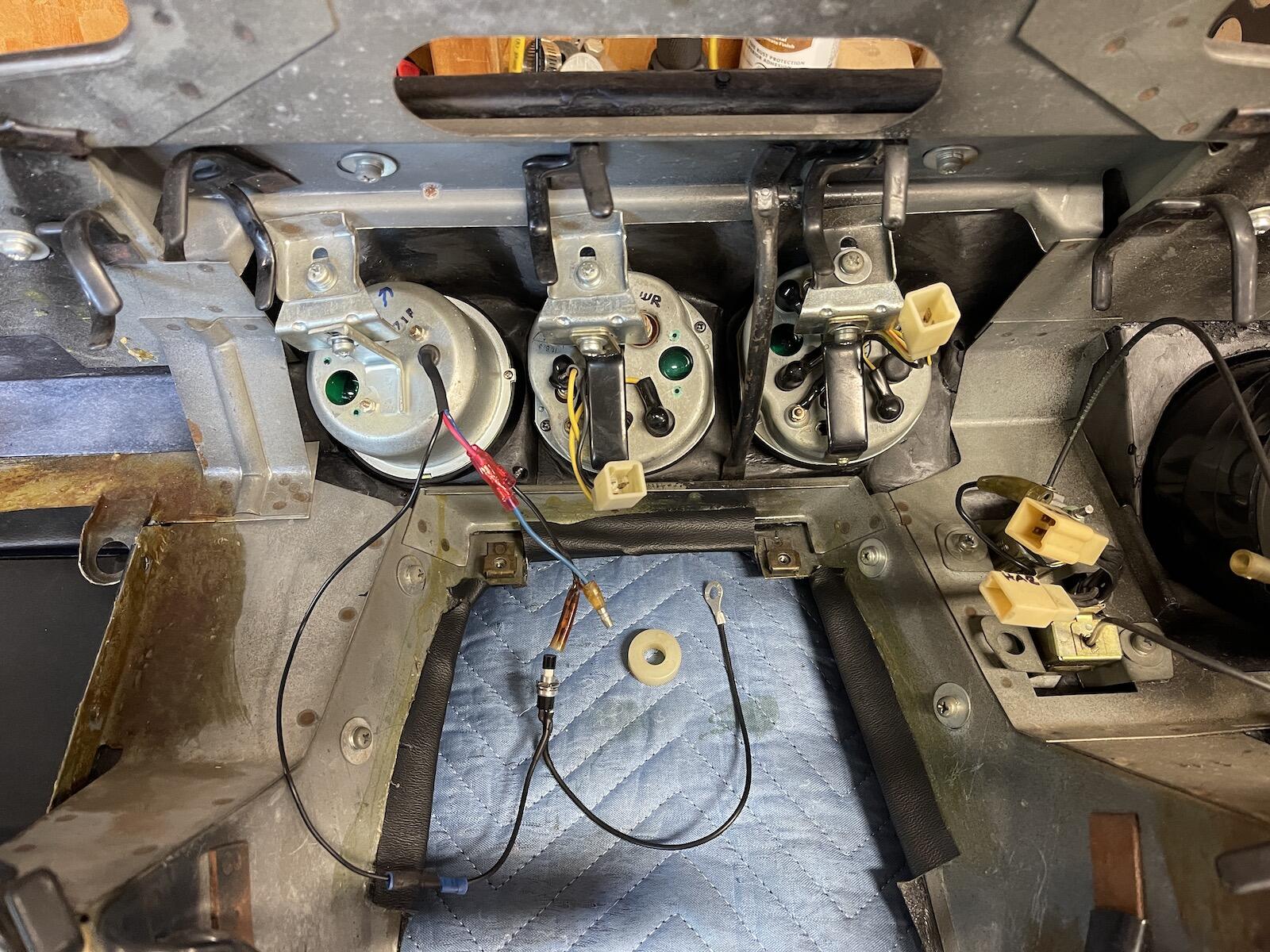
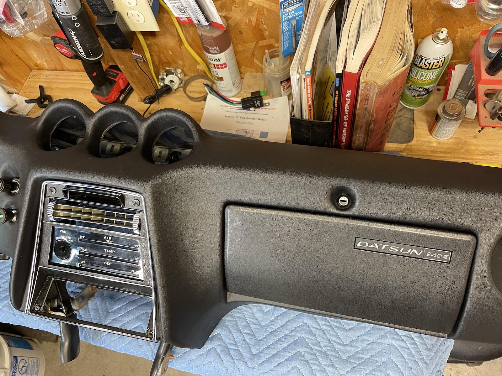
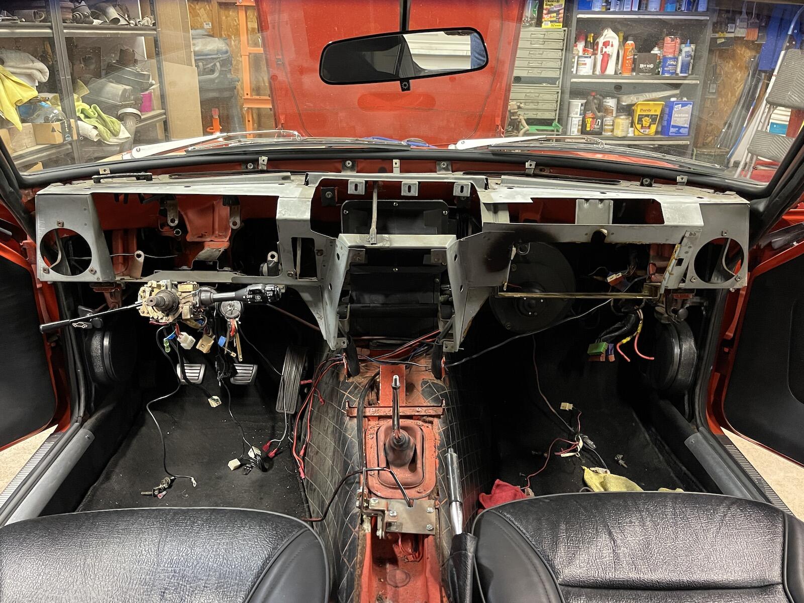
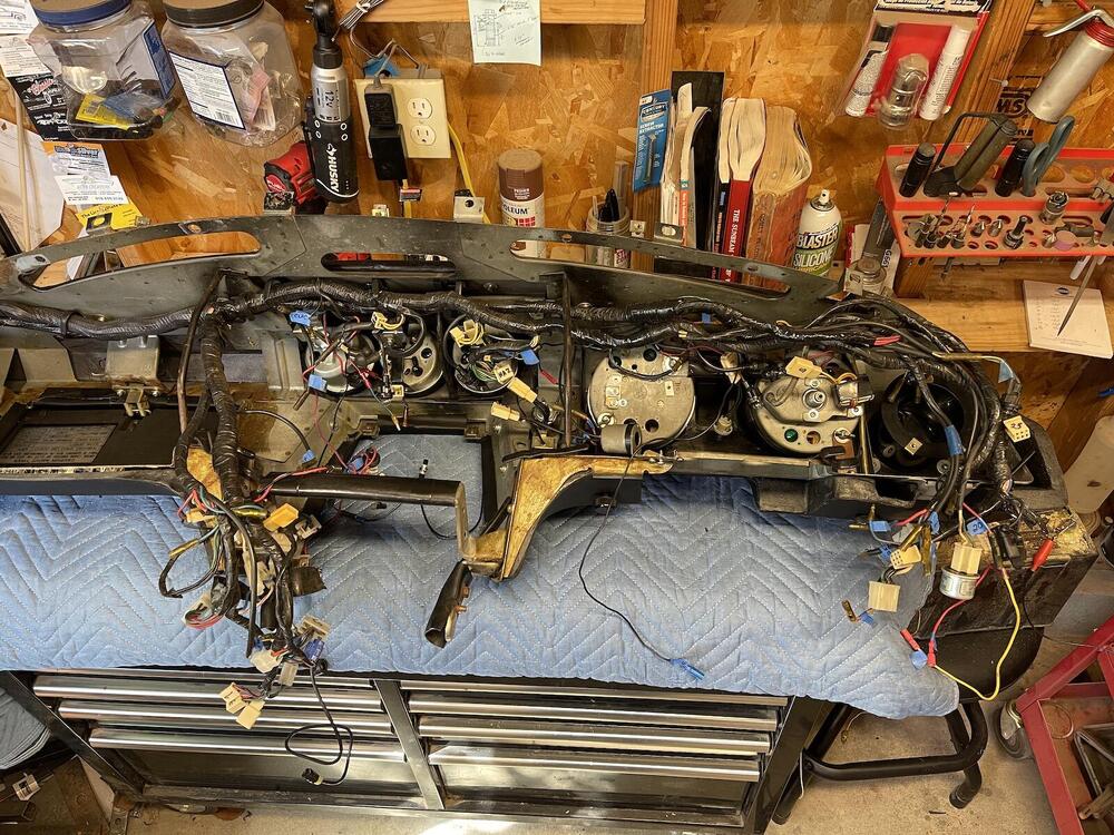
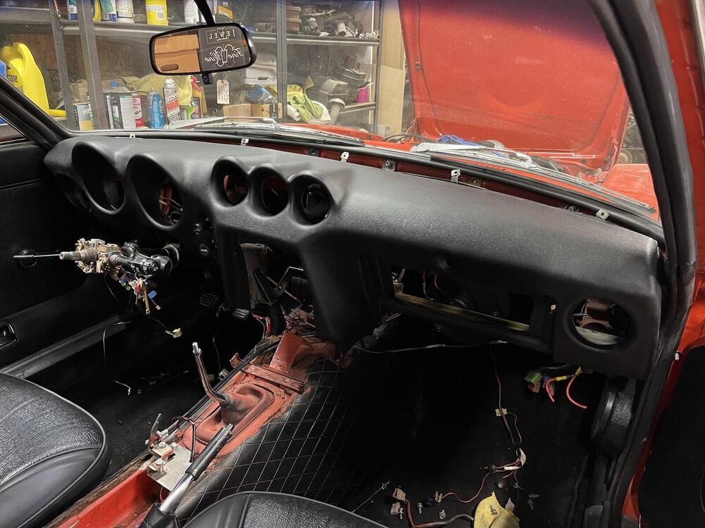
Just a note, connect amp gauge wires before installing gauge. Much easier. And, route the wiring harness above the tach and speedo before installing those two gauges. Also, what is this thing circled in red? The ground wires for the lighter and hazard switch connect to it. And it has a light socket (I assume the gray light goes there). Looked in FSM, 73 wiring diagram, Goggled it, etc., no luck. Still tracing out wires for the tach. Thanks!

-
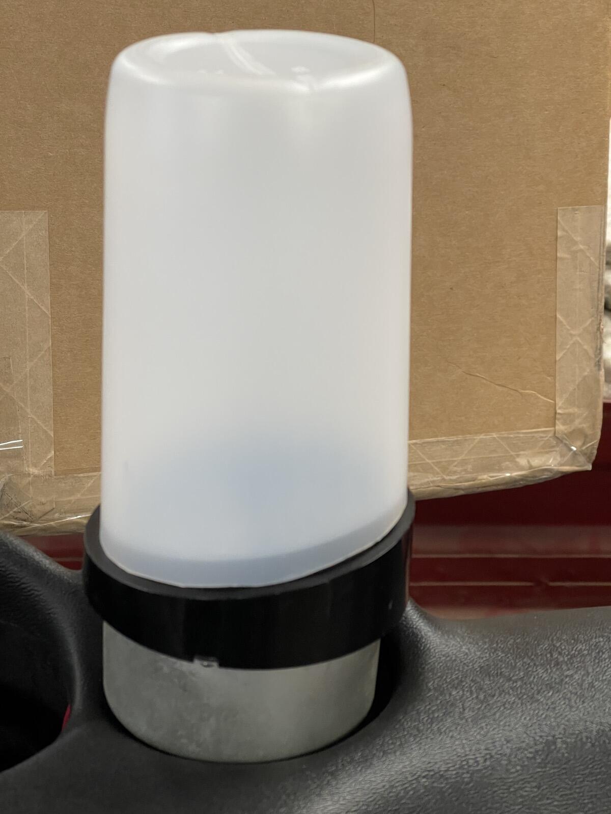
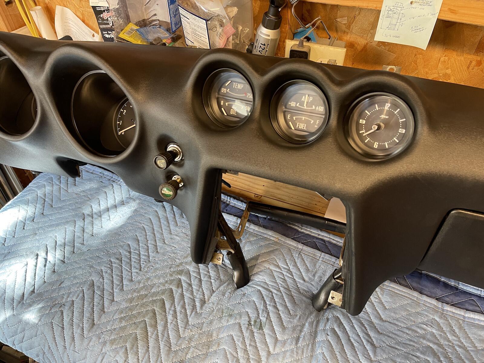
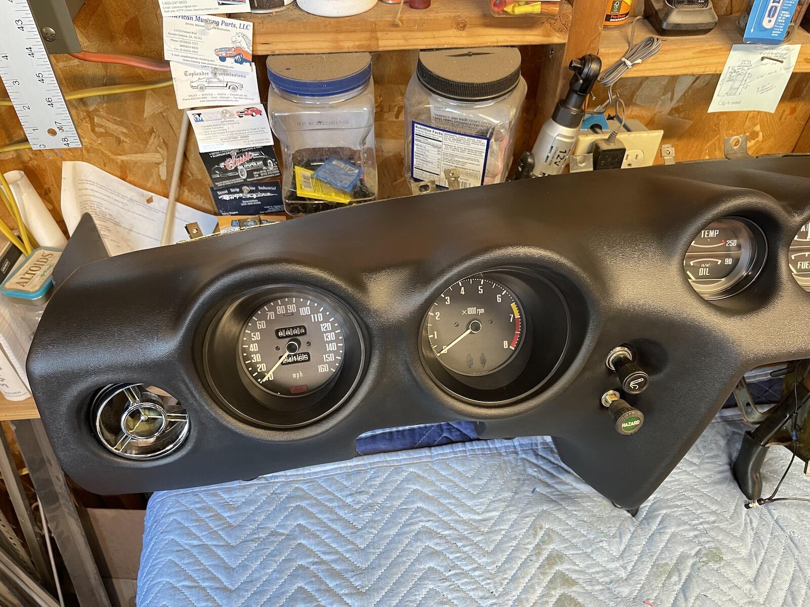
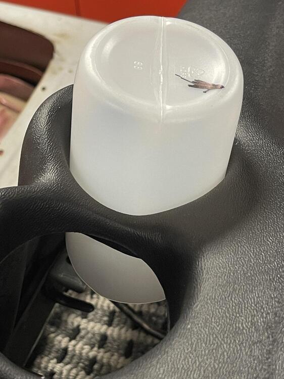
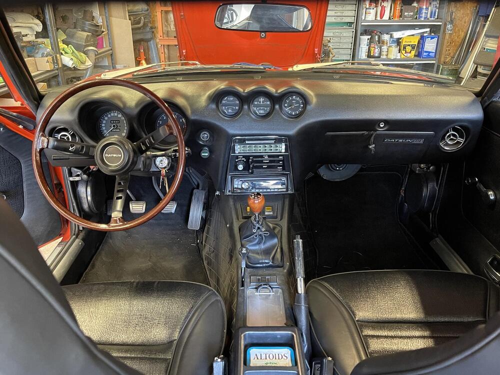
Got the gauges ready, clock converted, and right dial in the tach, and tested. I had a small paper gasket on the back side of the speedometer dial, around the needle shaft, that came loose, and it dropped down slightly covering part of the odometer, so had to take speedo apart to remove that. Cleaned lenses with Meguiar's PlastX, which worked good. As I was putting the clock back in the new dash, I noticed the dash holes were a bit tight, and had to pry the opening a little while pushing the gauge from the back. I didn't like the idea of prying on a new dash, even if it was a plastic tool. So, I found a plastic bottle, just the right size to fit through the dash hole, and fit around the gauge bezel rim, after cutting at a matching angle. And it was slightly tapered, smaller at the ending I poked through the dash hole first, wider at the gauge end. Once the bottle is shoved halfway through the hole, I put the gauge up inside the open end of the bottle and pushed gauge up against the back of the dash, and pulled bottle off. Worked great, plus no messing around the front of the dash gauge opening. I think it was a Clorox wipe bottle, but I'm keeping it! I'll bet the factory had something similar, but better. Gauges are mounted. Moved the old clock wires over to the new clock wiring, and have an adjustment switch ready to mount somewhere, not sure where yet. I also have this leftover part, that white spacer that fell out while removing the gauges. Can't for the life of me figure out where it goes, or even if it's needed. If anyone recognizes it, please let me know. 🤔 Now the fun part, connecting wires back up.


-
LOL! I didn't even notice that! Chinese humor, or they think we are idiots!
-
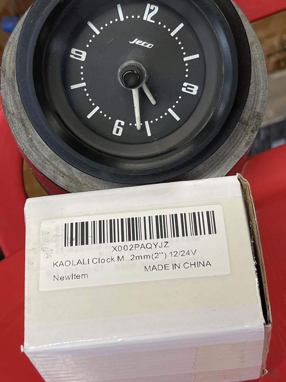
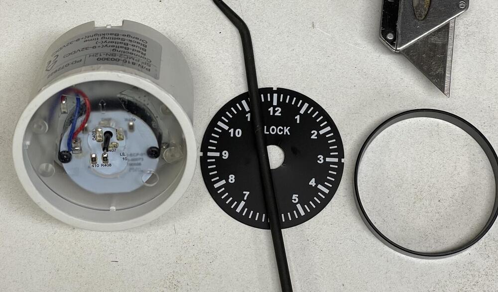
Yeah, I doubt a resistor is there. Looks like the tach is feeding from the Black/White wire going to the coil. And reading this thread, it looks like the need for a resistor is sometimes not needed, maybe depending on the electronic ignition used, I don't know. But something is funky with my tach wiring, I still need to work it out. On my clock, I stripped it down to the mechanical clock mechanism, cleaned it good, lightly oiled pivots with clock oil, no luck. Took apart motor too, cleaned and oiled. everything looked okay, worked for awhile, then quits. Beyond my capability. So, I ordered this electric clock off of Amazon for $40, and finessed it into the housing. I thought of just painting the orange hands white, but decided to clip the originals and epoxy them to the new clocks hands. I may still get some Testor's paint and mix up the right off white shade, and paint the hands. Plus I'll have to mount a small push button (negative ground signal) somewhere hidden under the dash or in glove box to adjust the time. I'm running it overnight to see if swinging the little extra weight of the hands affects it's accuracy.

-
Yeah, it had 3 wires. I'm going to have to trace that wire that supposedly goes to the coil.
-
I couldn't get that method to work. Maybe the newer battery chargers are too smart and figure out there's no battery hooked up to it. I hooked the 260/280 tach with the single signal feed to my Sunbeam Tiger, which also has a Pertronix. And it works fine! It read high at 2000 when the Ford 260 was at 1500, which makes sense. So, I'm going to move the 7000 redline dial the that newer tach, should be good to go. IMG_7803a.mov
-
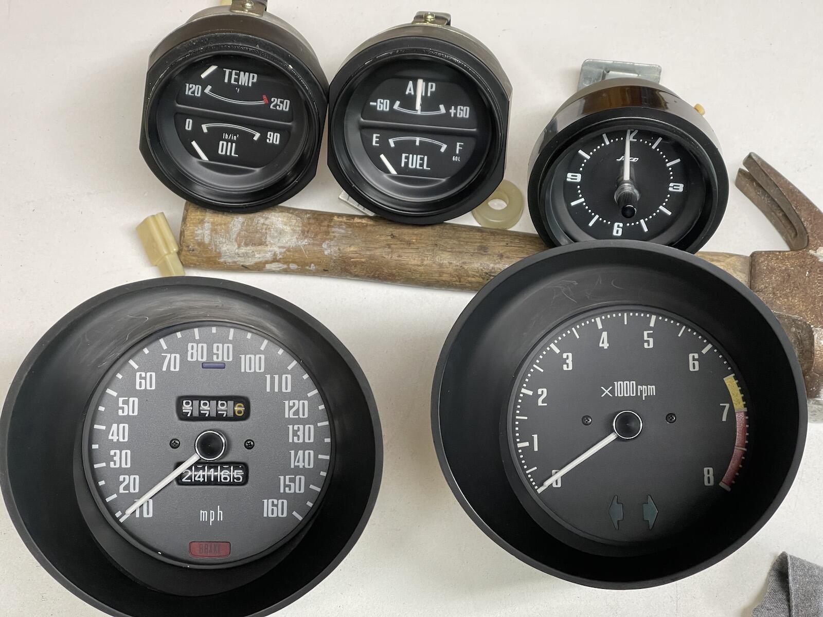
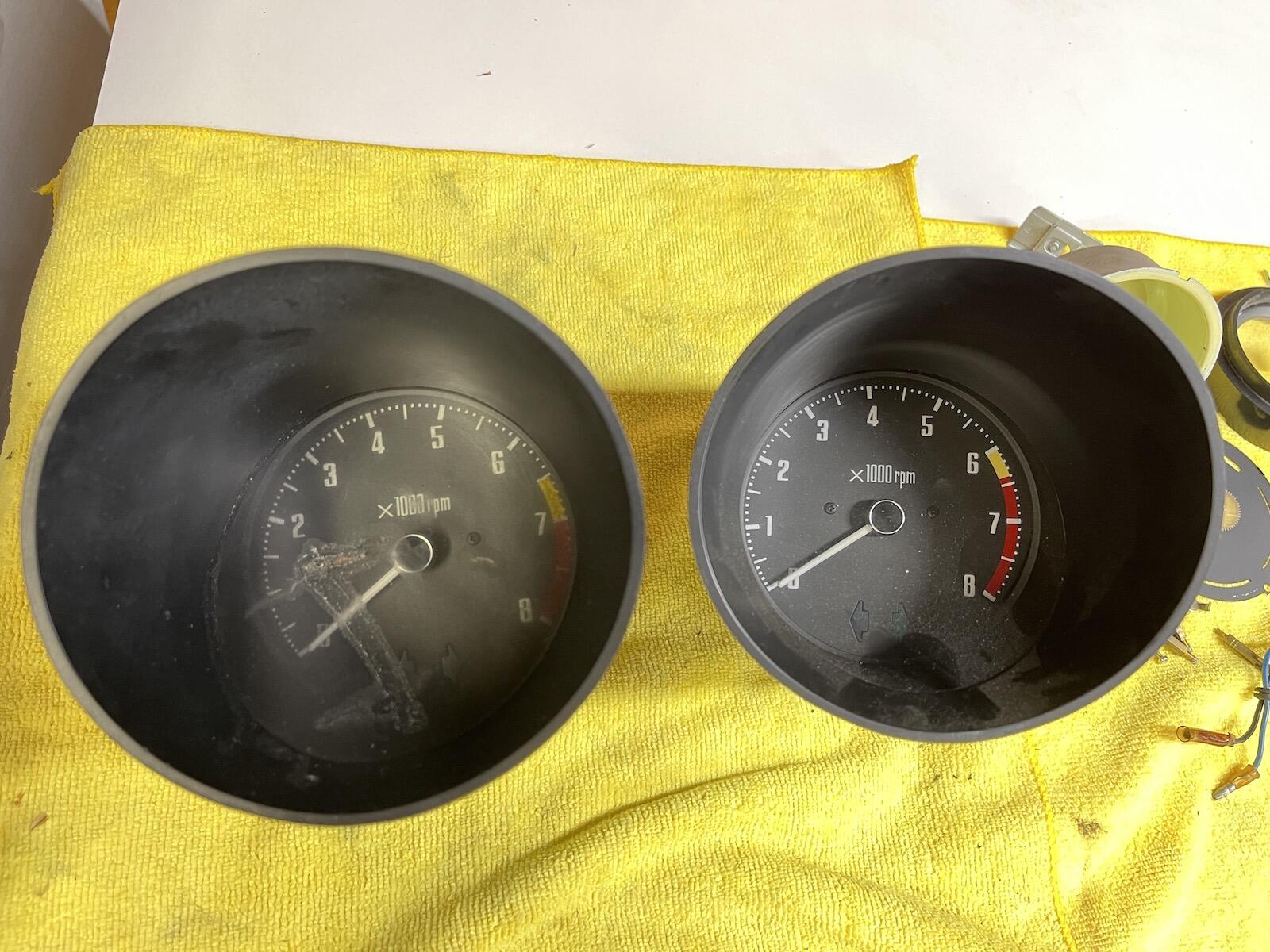
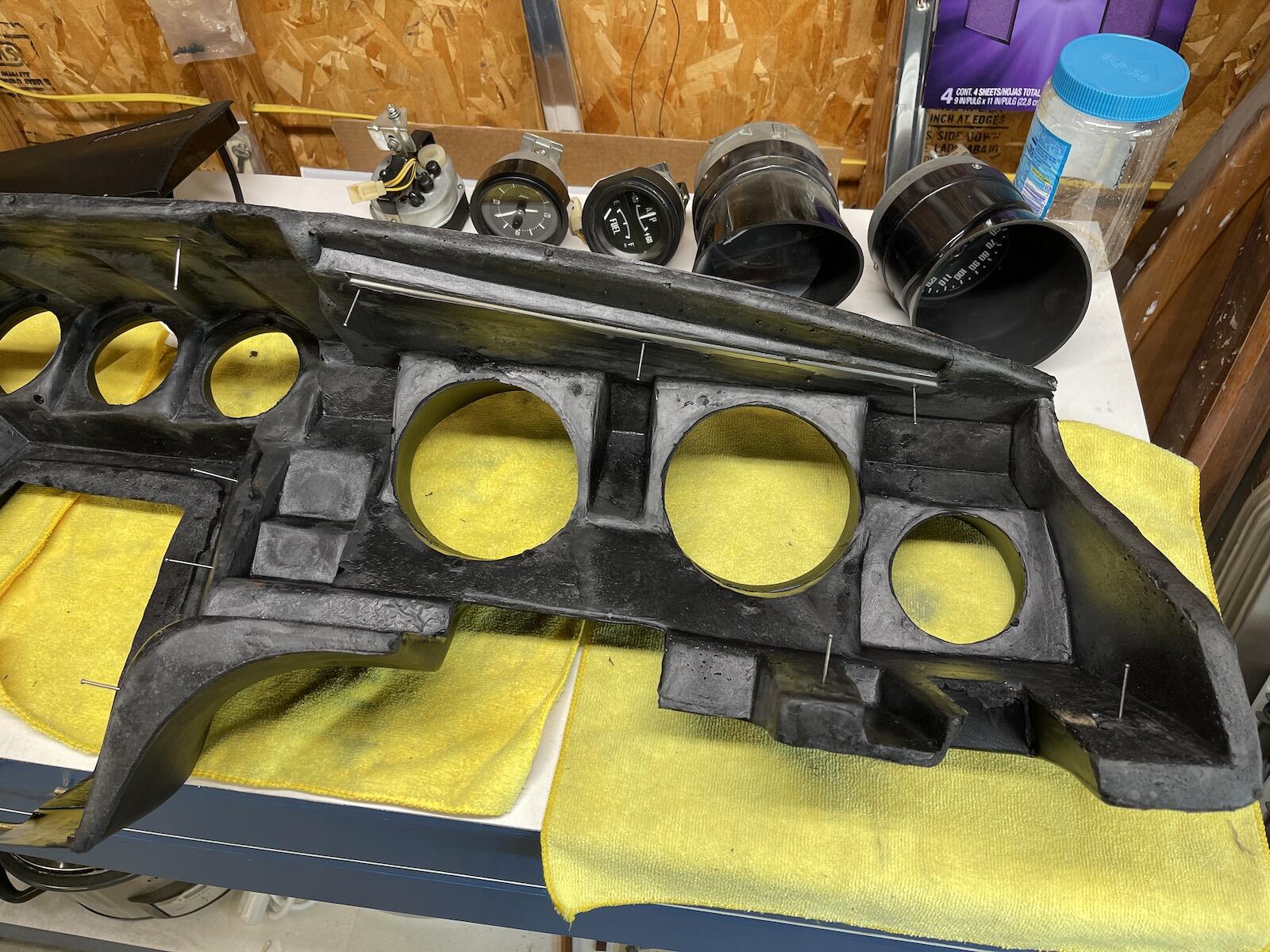
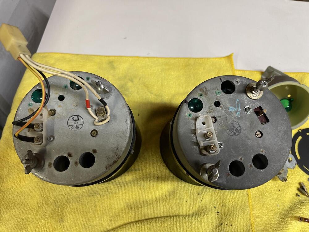
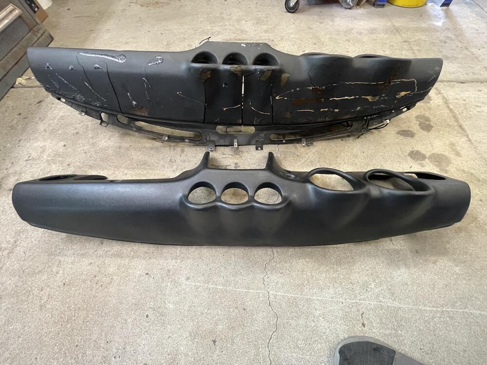
Got the edges glued, and test fit the center panel and glove box. Glove box works fine, not more string to pull it open. Getting new correct fasteners for the center piece. Now onto the gauges. I took the clock apart, tested the motor, which works. I might just try to clean it up and lightly oil with the correct stuff. Wait time on quartz conversion is 14 weeks, so maybe I'll hunt around for one already done. Might be nice to hear a ticking clock though. The tach has never worked in this car since I bought it. Not see sure what year tach it is, it has a 6400 redline. And I've got an old one, correct dial I believe. Pictures below. Looks like the one on the right in missing the loop wire on back. Is there a way to bench test these? Thanks!


-
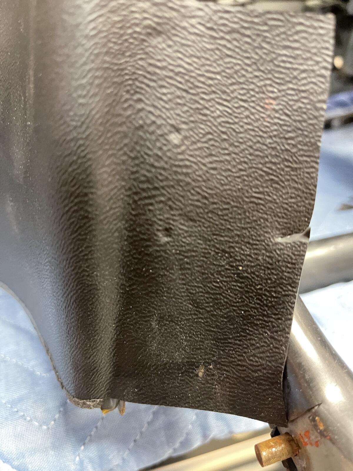
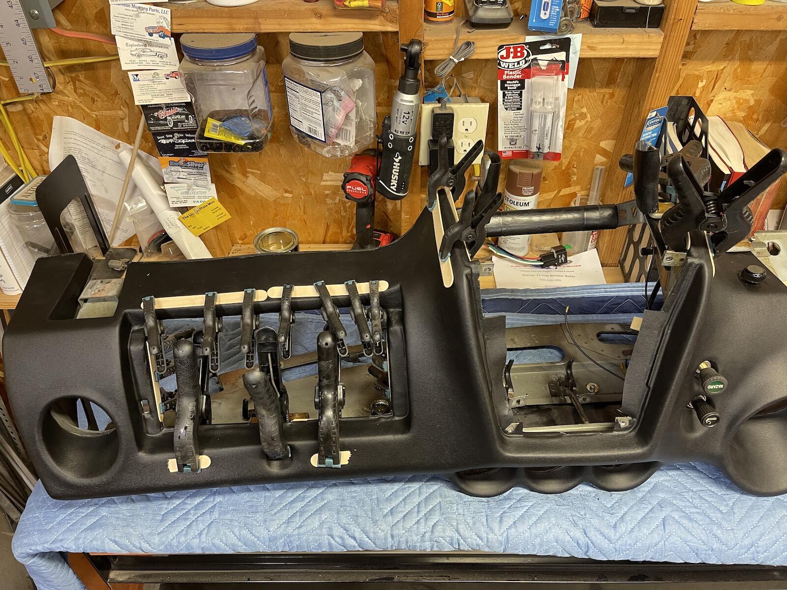
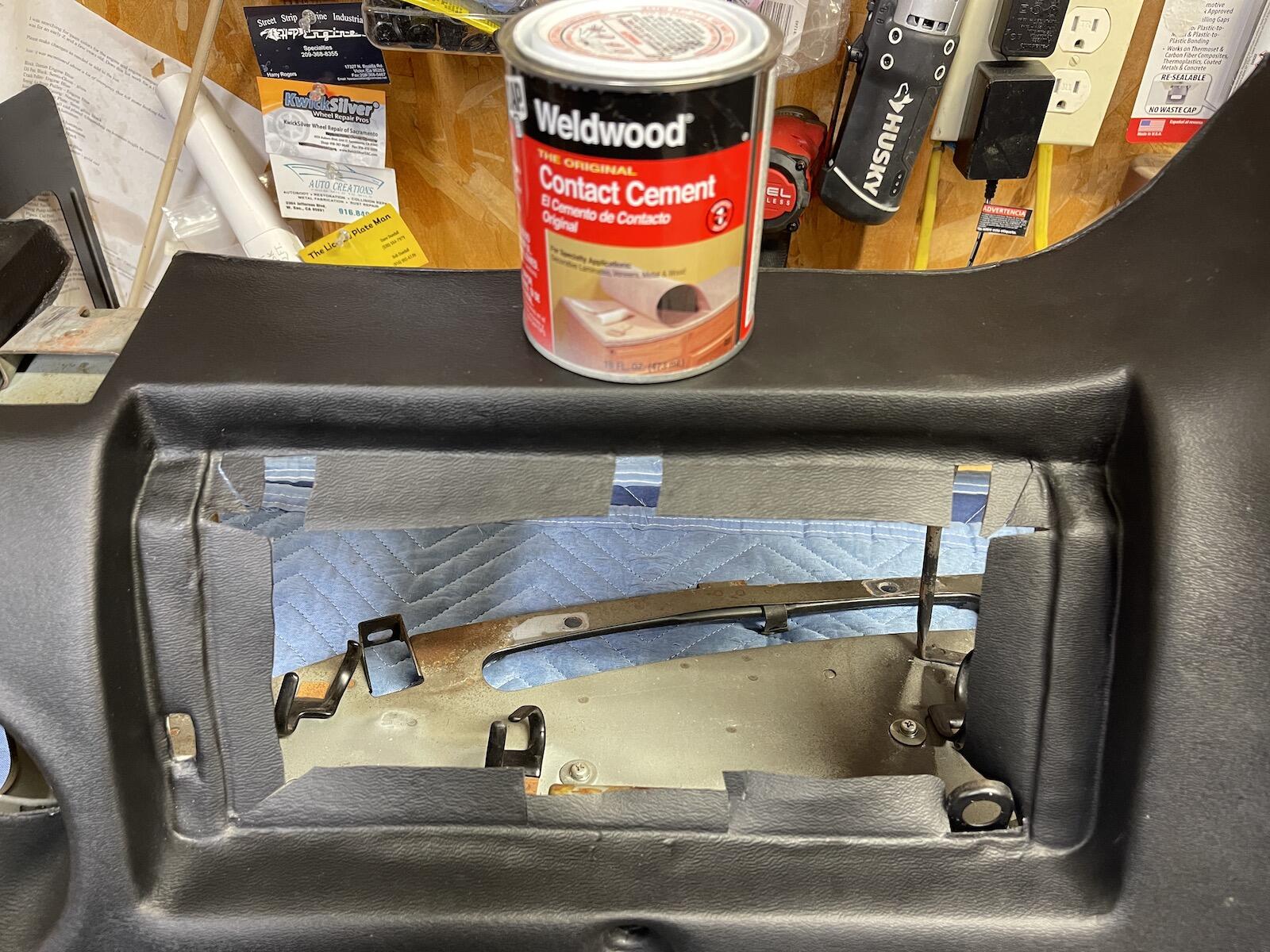
Got the center and glove box openings trimmed and ready to glue to the frame. I tried to generally match how the original dash was trimmed in the openings. Borrowed a friends solvent based Weldwood contact cement, hopefully it will hold good. I think these small dimples may be suggested cutting lines, I ended up cutting fairly close to them as I was trimming. Using stir sticks and clamps to hold overnight. I've got my 10mm 3/8" socket in the glove box button hole so dash is not getting deformed by the clamp. I ran out of clamps, so I'll finish the center tomorrow.


-
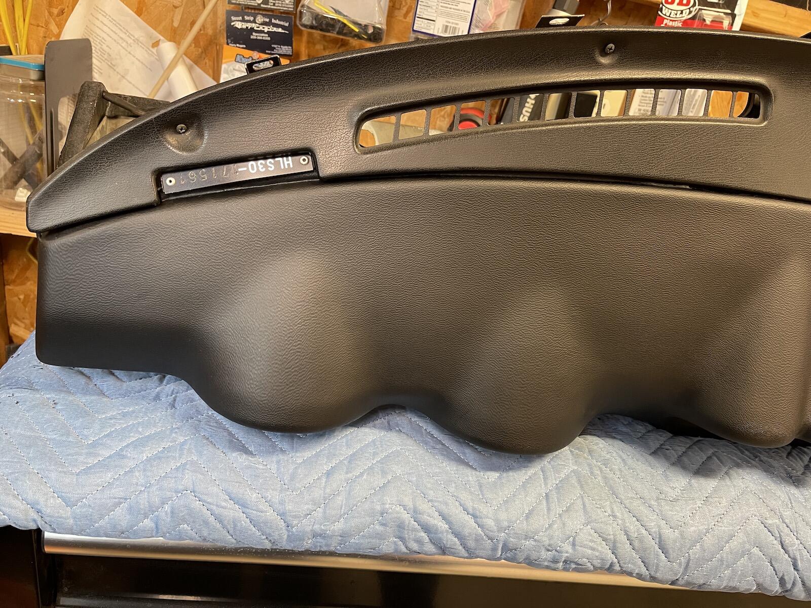
Thanks Dave for the suggestions! 👍 That's quite a set of videos you have up there! I attached the defrost vent panel to check the clearance between it and the dash. Looks good. I should paint that panel, but I'm afraid I won't get the right sheen and won't match the dash. Did a dry fit into the car to see how it fit, and any clearance issues with the doors, etc. I still haven't figured out how this car got so much overspray on the inside, shifter boot, wiring near the harness and relays, even some of the diamond tunnel covering. It wasn't a color change, and no floor or frame work has been done. What the heck were they trying to accomplish?

-
Ha, yeah, I know the feeling! I've never done a Z dash before, and I'm not trying to pass myself off as an expert. Just showing what I'm doing and hopefully get a few tips along the way. 👍
-
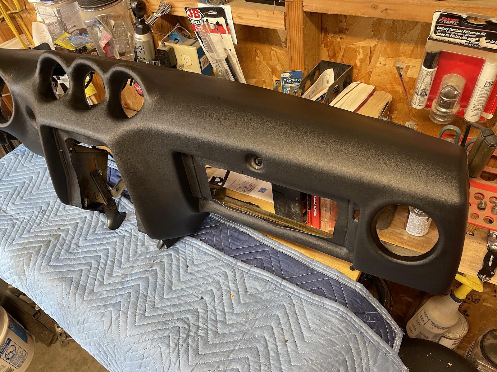
I've got the new dash screwed to the frame. Glad it wasn't a 50 year old original dash pad, as much as you have to muscle it in place to get the holes aligned. New one has some flex to it. Got the holes drilled/cut for the hazard switch, lighter, dimmer, and odometer reset. Next is cutting. trimming, folding the edges, and gluing to frame, around the center and glove box opening. I assume that is what others do.

-
I screwed the vent panel in place and marked the edge, just so I know the top edge is forward enough to "hook" the top front edge of the dash pad when screwing pad to frame. Nice that the new dash has the same molded in place steel rails to screw into. There's 17 screws, here I've got finish nails sticking out of each hole. I should have ran a screw through each hole just to get a thread formed instead of waiting while trying to mount to frame. I also marked each hole with a marker which helped while positioning the dash over frame. I worked from the center outward.


-
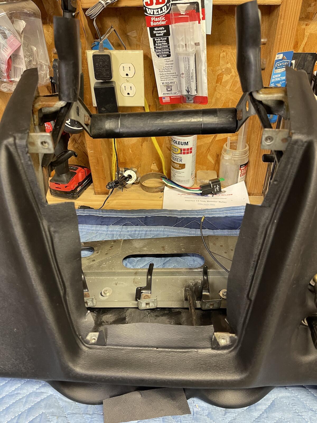
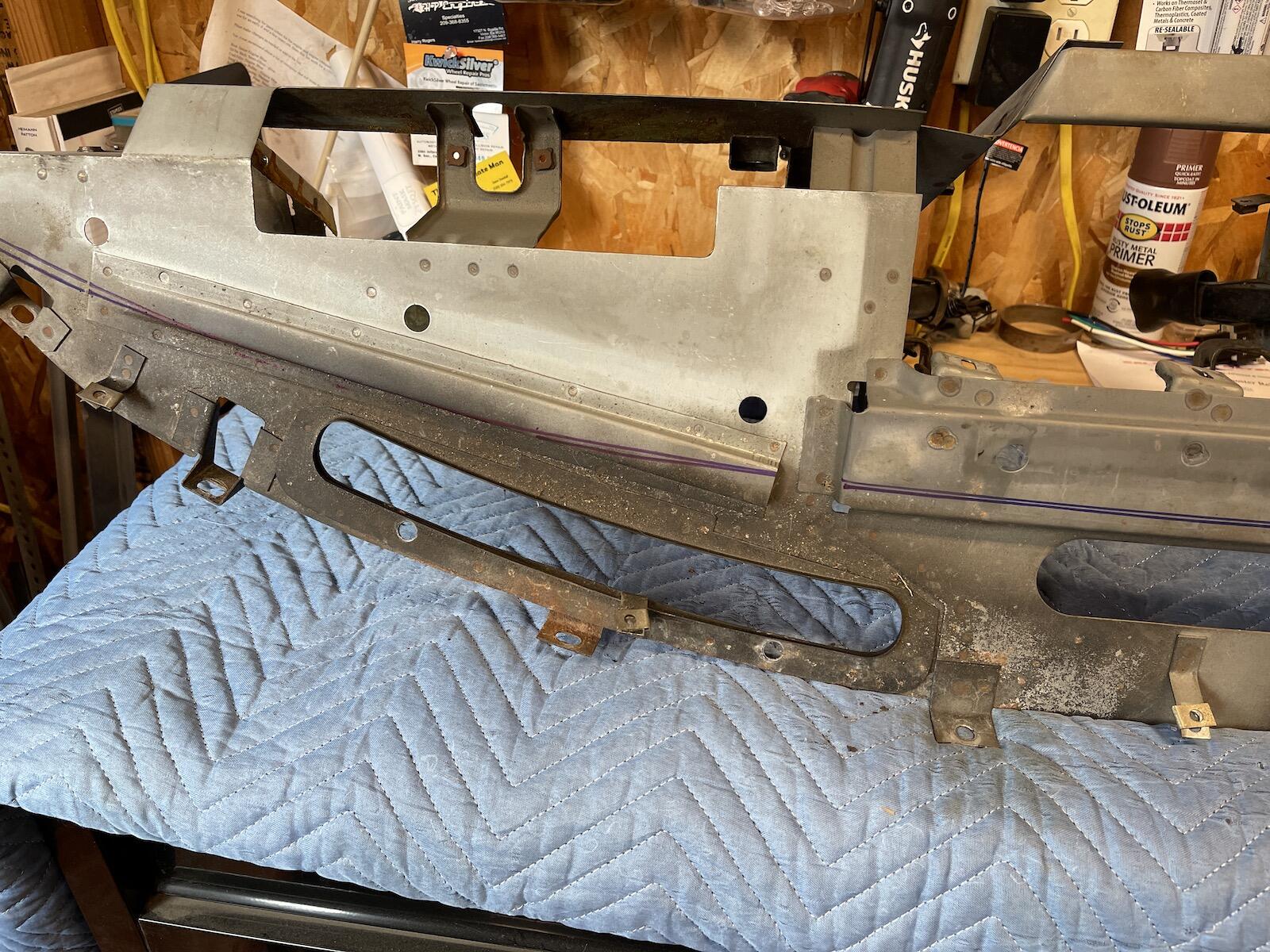
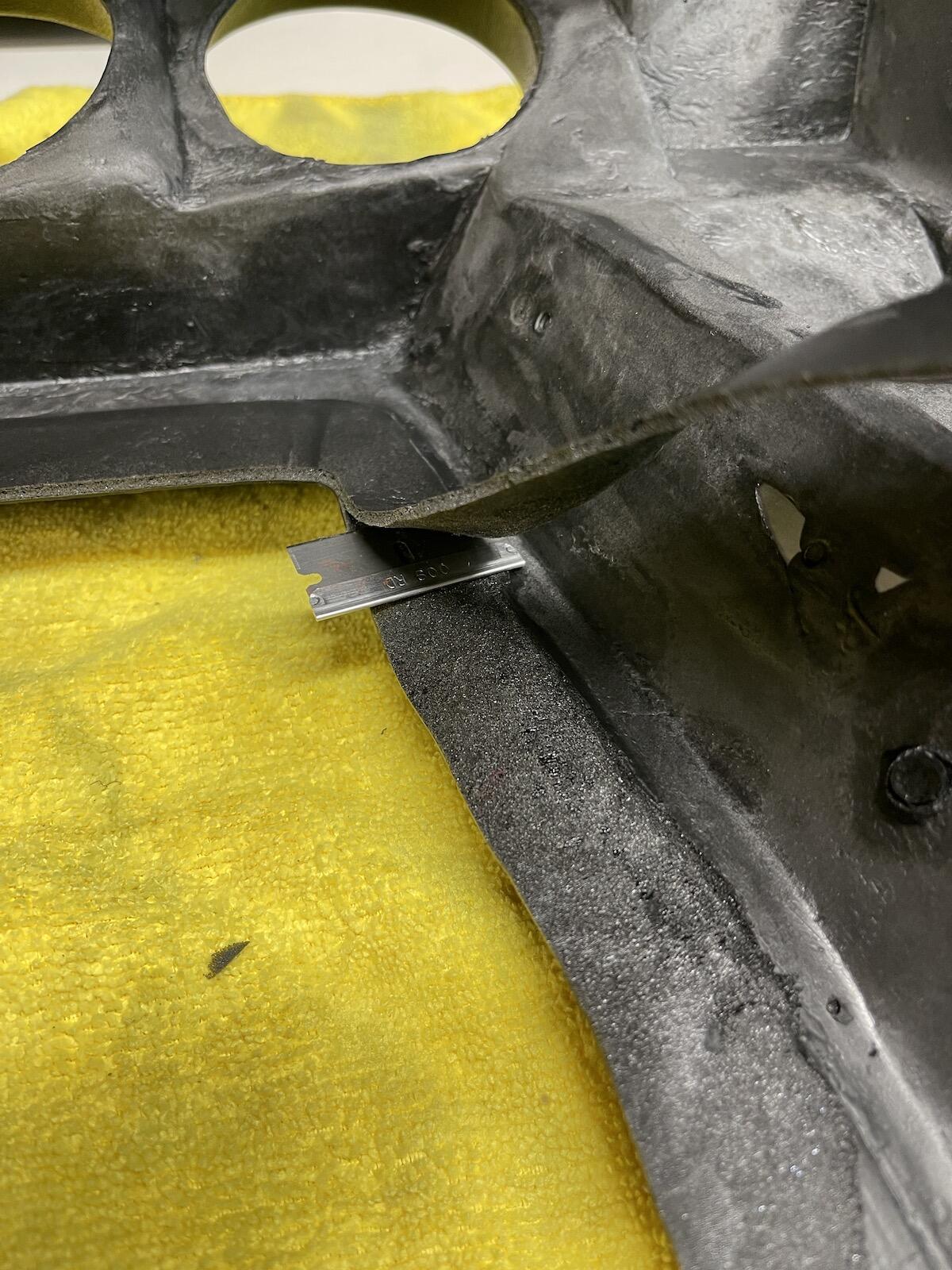
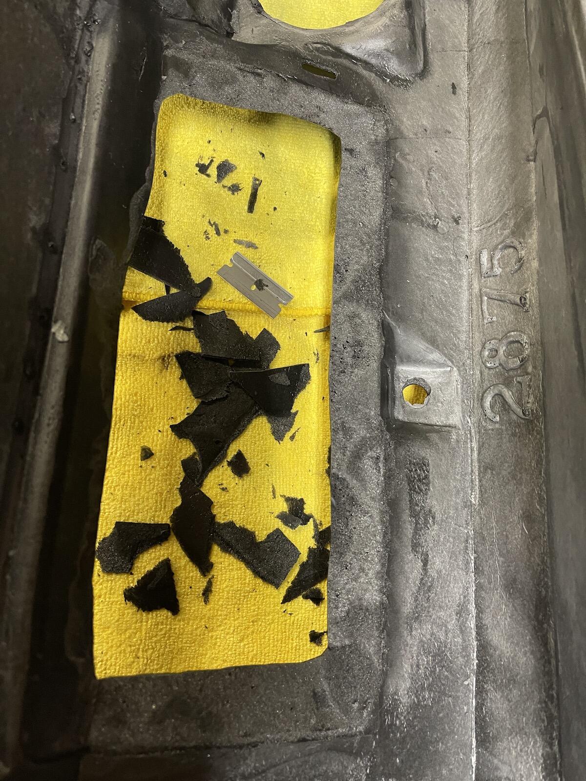
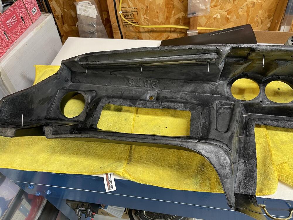
Good idea, thanks for that. I mounted the dash frame just to get an idea of the bolt in process, without all the weight. Pretty ugly. The edges that will need to be slit and folded around the frame is kind of thick, like 1/16" or more of dense foam on back of the dash. So for the glove box and center panel opening, I used a blade to thin it more like the original dash, as close to the outside material without cutting through. It was like filleting fish! I may have to drive over to Reno to get some adhesive, since California has banned all the good stuff. Weird that it was left to me to do that cutting, but I can't imagine a thick piece like that being wrapped around the edge and being held in place with contact cement! Maybe I'm missing something here.


-
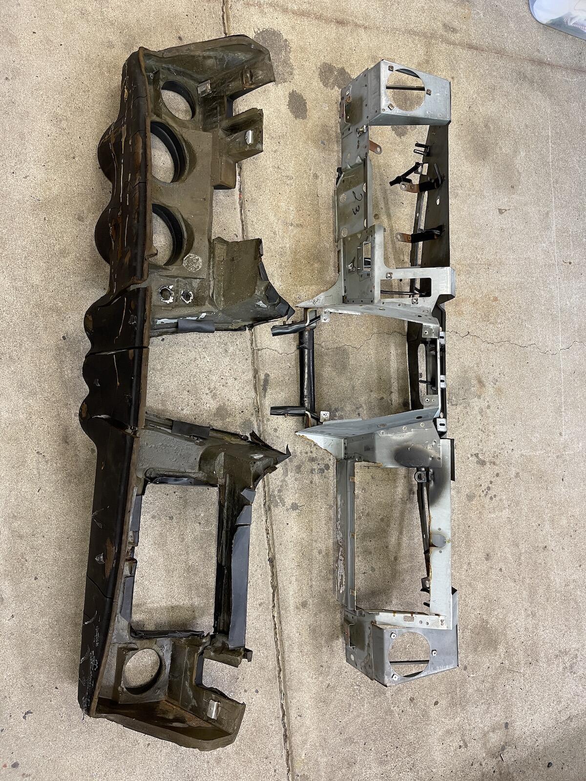
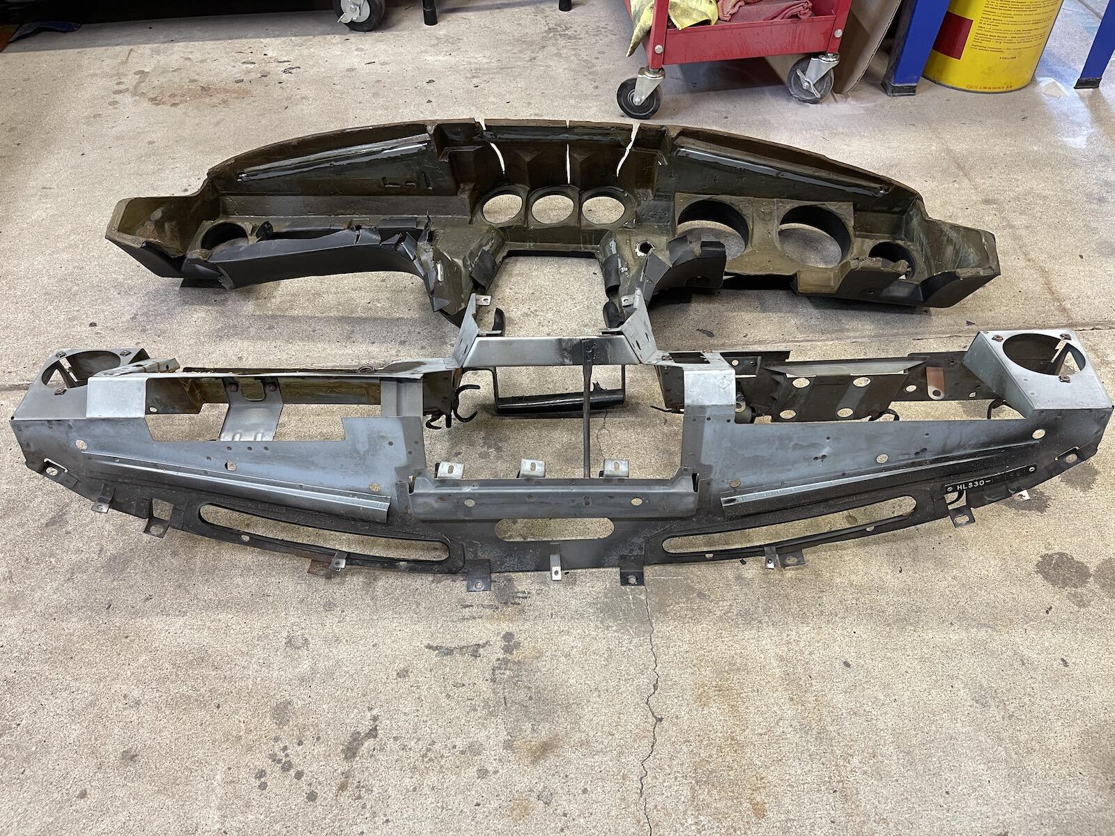
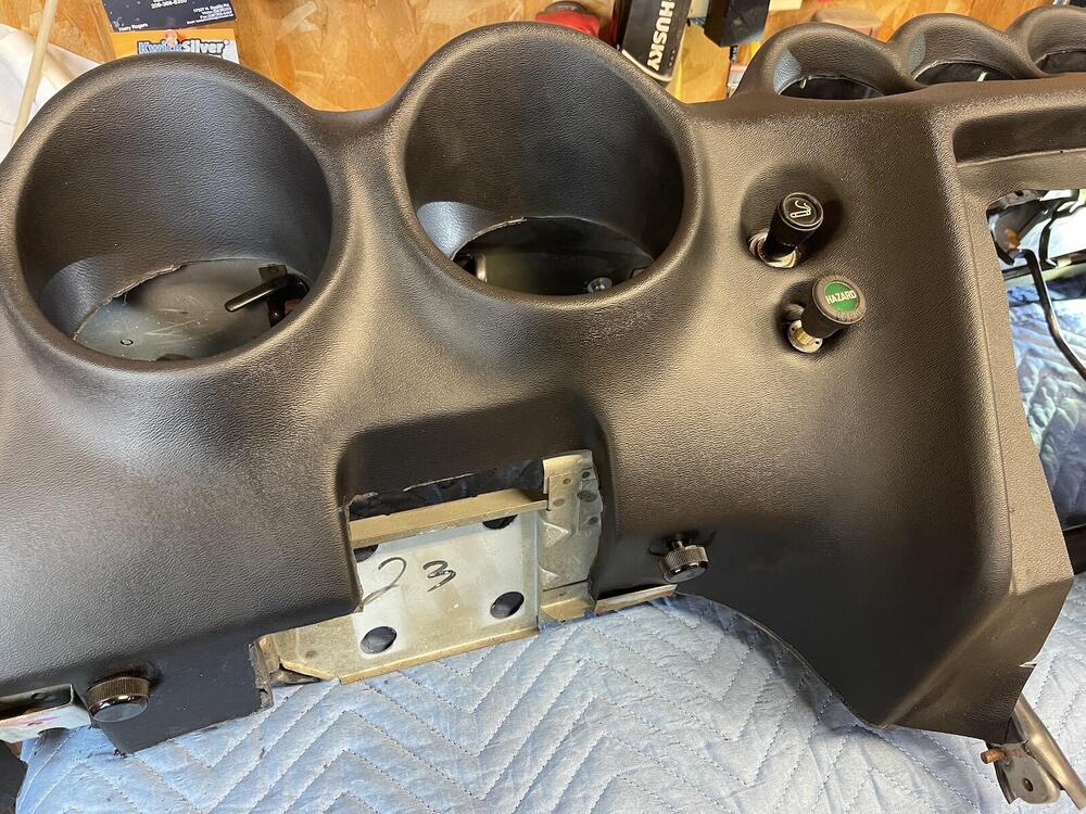
Now I removed the cap from the original dash. To remove the various knobs: Odometer reset: small set screw at speedo end, and pull knob off, remove cable. Hazard switch: push knob in, twist 1/4 turn counter clockwise. Lighter: 1" socket works to remove nut on back. Panel light knob: pull off, remove 2 screws from back. Luckily there wasn't too much adhesive holding the cap on, and it took about an hour of carefully prying it off the dash without cracking it. I'll probably sell the cap eventually. Once the screws that held the dash to the metal were removed, it slid right off.


-
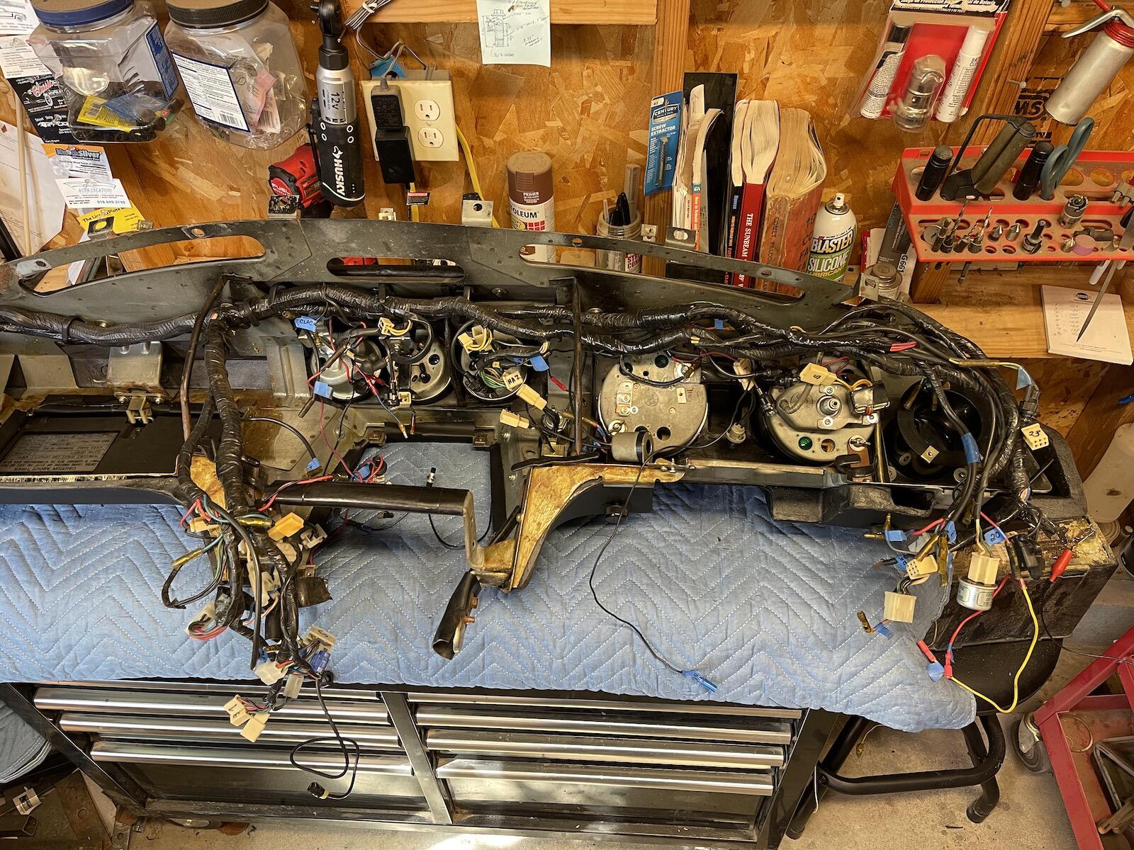
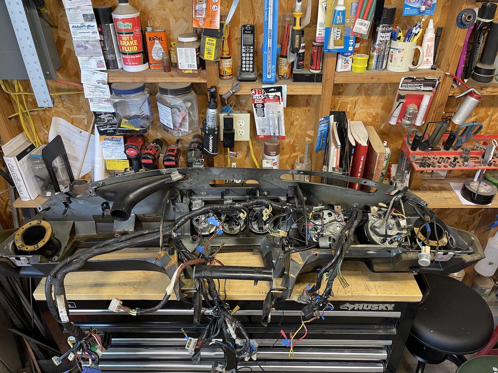
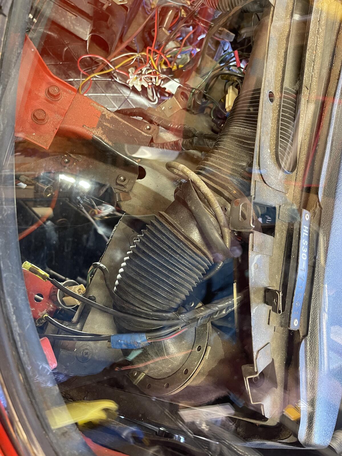
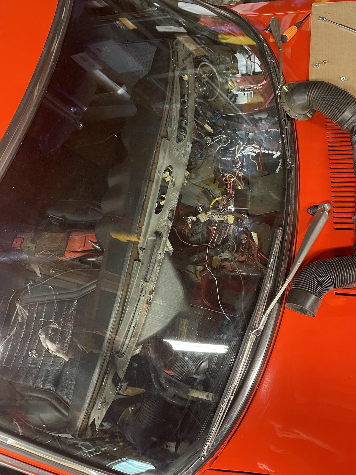
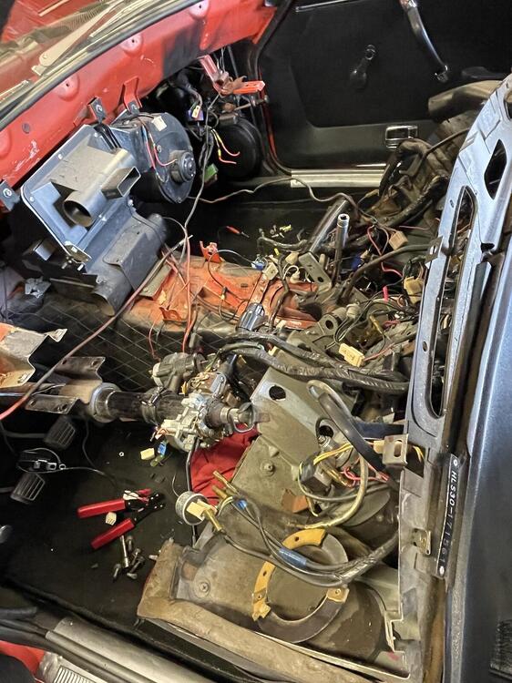
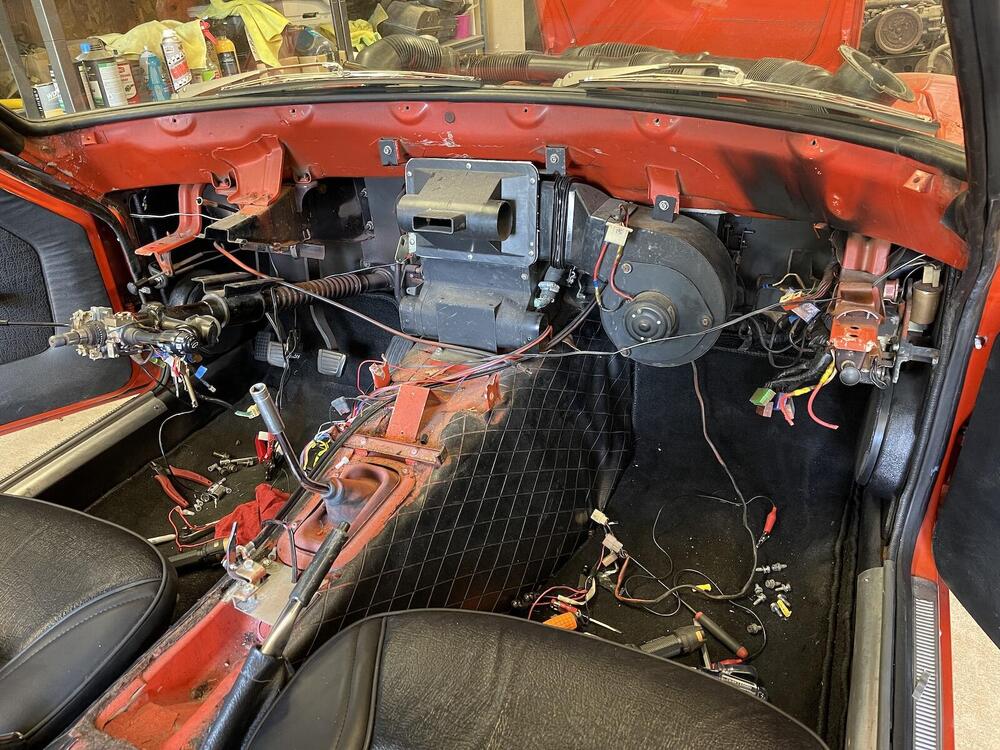
I marked all connectors and and worked slowly removing all wires. Plan was to disconnect the multiple plugs on the right side and leave wiring harness attached to backside of dash. Removing ducting gives a bit more room to work. Luckily the wiring in this car isn't butchered with splices, only the radio connections had to be dealt with. The two main power feeds (large white and white/red) through the firewall had crimped butt connectors, so I assume the dash has been out before. I should probably check the heater core too.


-
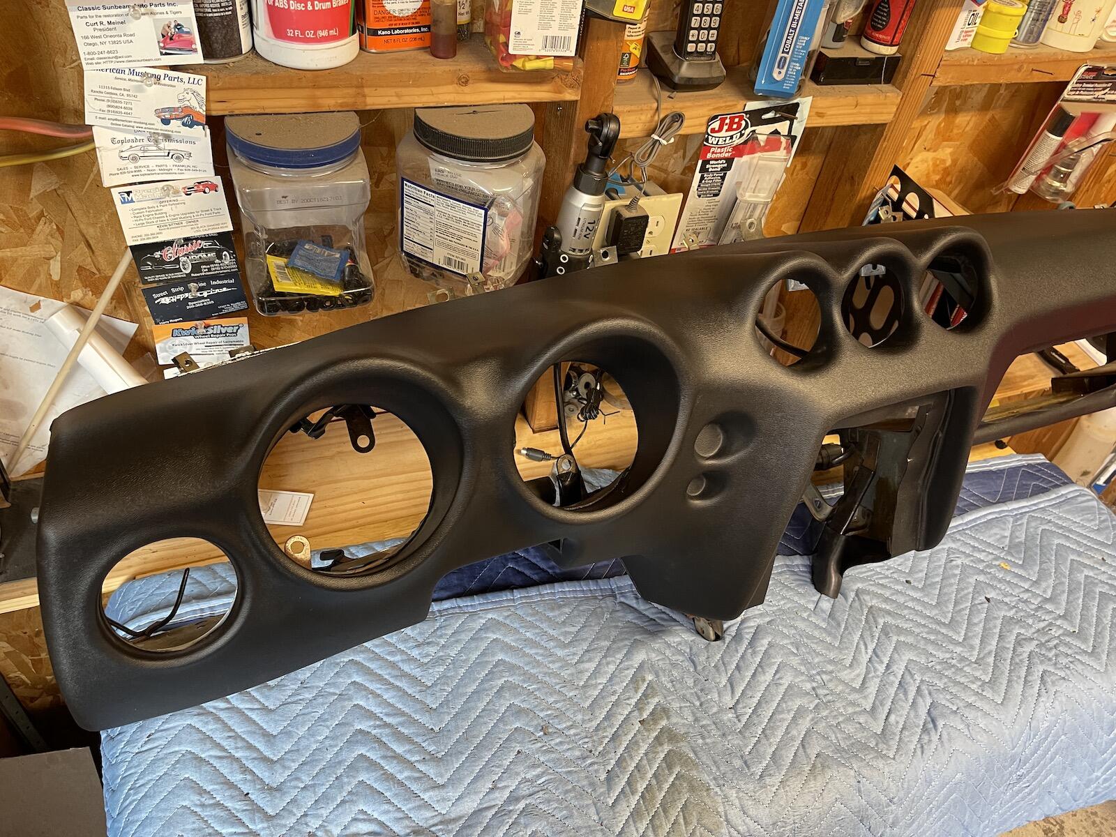
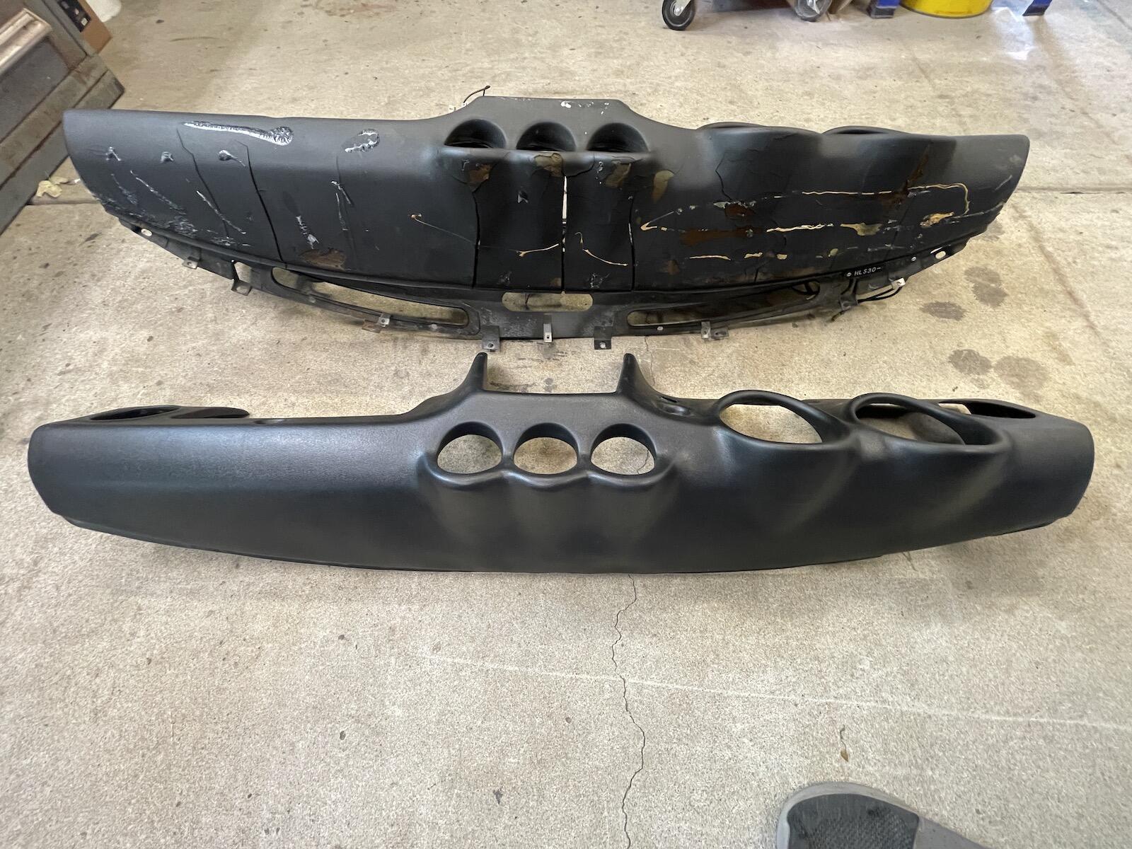
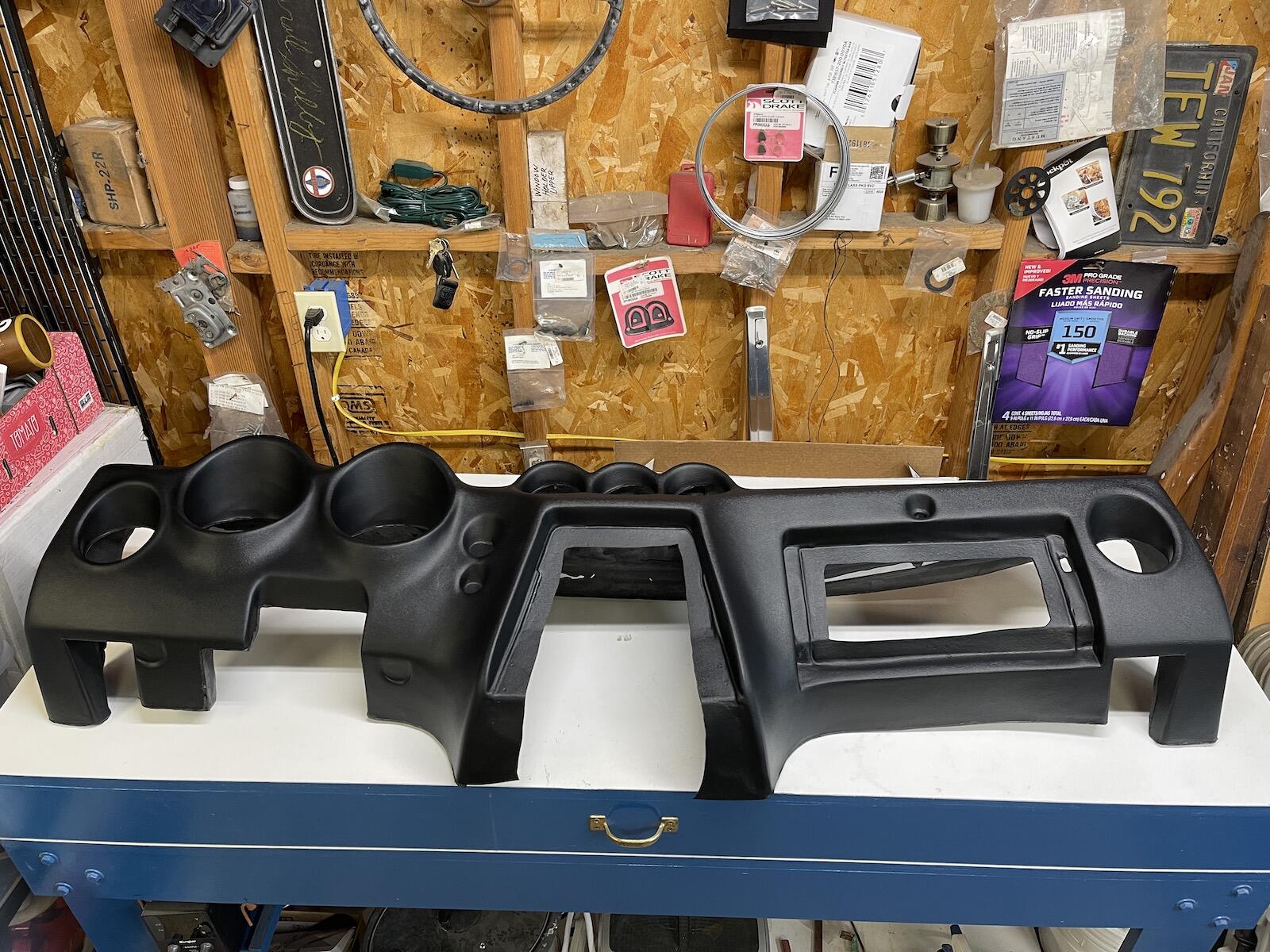
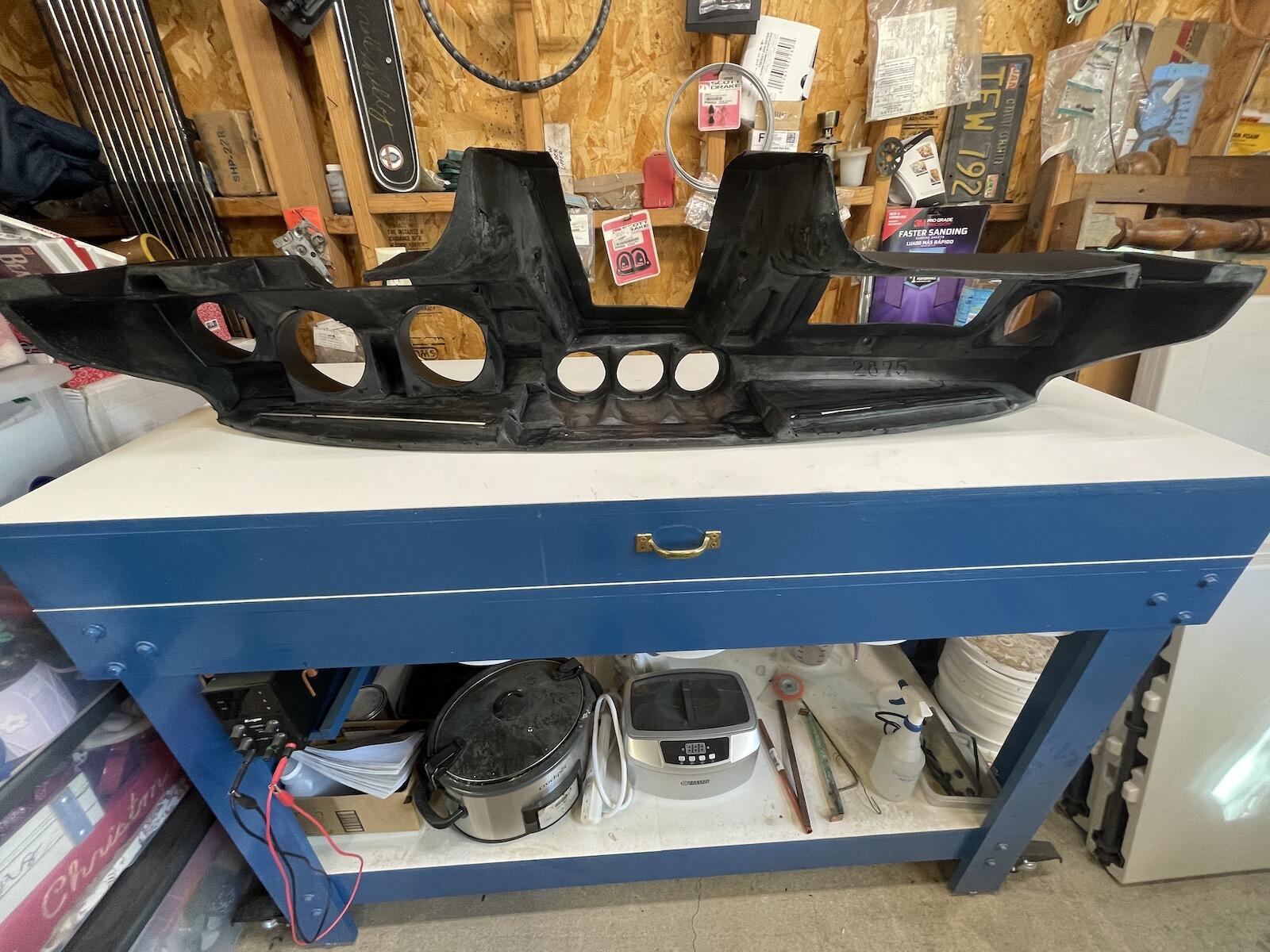
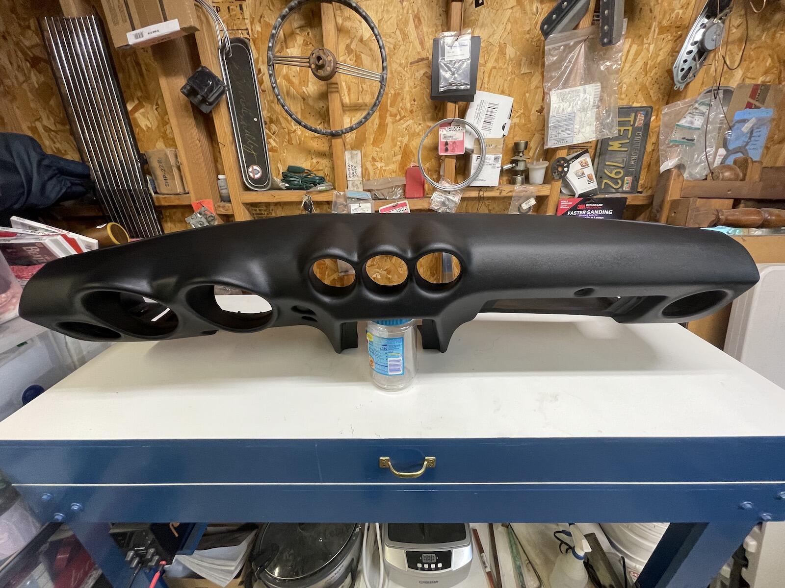
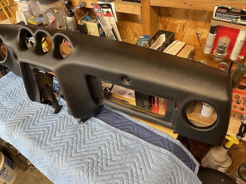
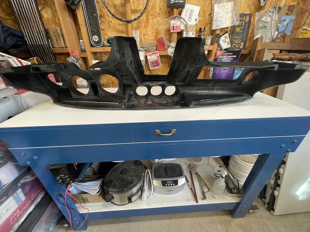
I ordered a reproduction dash from Vintage dashes December 2021, finally received July 2022. Been psyching myself to do the replacement, since dashes a wiring are not my favorite to work on. When I purchased the car 8 years ago, it already had a full dash cap installed. It actually looked okay, but the tach has never worked, and a cap prevents the removal of the gauges from the front, at least for me. So I really couldn't do a proper repair of the tach. And I want to fix the clock, which always reads 2:40. All other gauges work fine. Here's the new dash: Here's the old full dash cap. Also the glovebox door fits tight and has a string to help pull it open. The fun begins....🤔


-
You could call Damper Dudes in Anderson, CA and see if they do Z dampers. They did a SBF one for me a couple years ago for $78 + $15 shipping. Or Damper Doctor in Redding, CA.
-
On HBO's Tokyo Vice, there's a Z driven by a detective. Light bar is on car next to Z, thankfully.

-
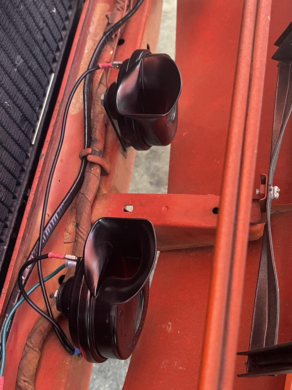
For now, I installed the Hella 007424801 horn set. Painted them black. I'll probably take a stab at rebuilding the old ones eventually. At least I have a working horn, and pretty loud.

-
Those same ones fit my 7/73 240Z fine, for what it’s worth.
-
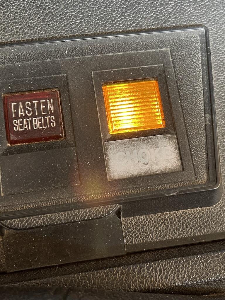
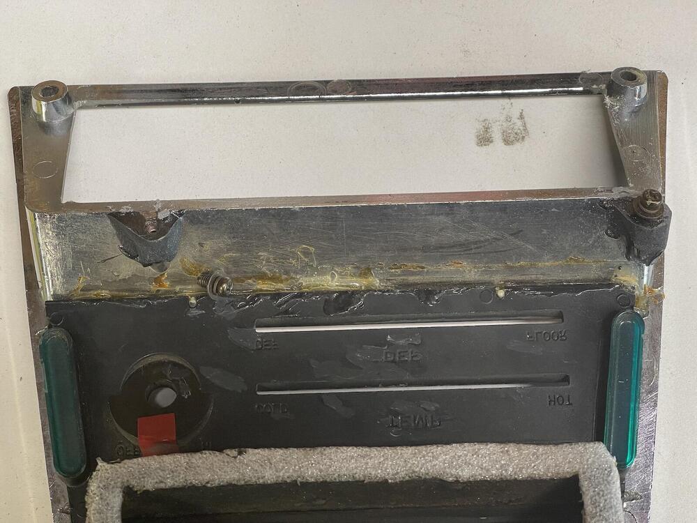
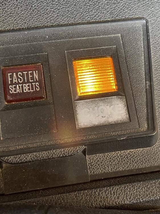
I'm looking to replace the choke light label on my console. Does anyone reproduce it? I found this old thread, but solution seemed to be to peel it off and whiten the engraved pictogram that's supposedly underneath it. Thanks
-
Whew! Good to hear! I was worried someone would buy them and say “Man, these things suck!” L O L
-
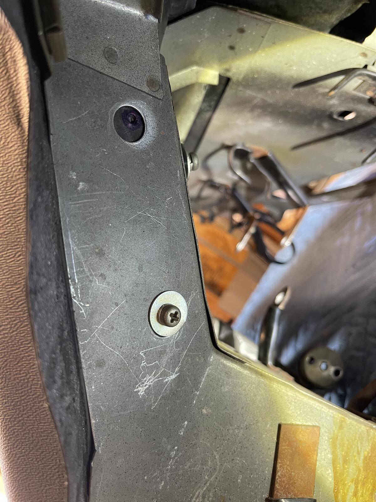
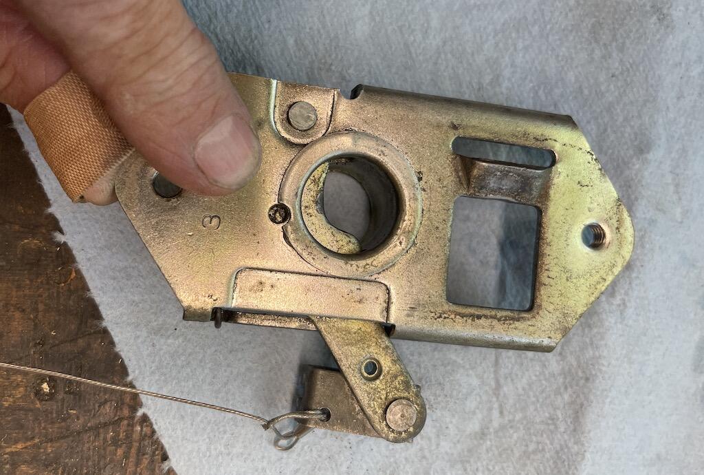
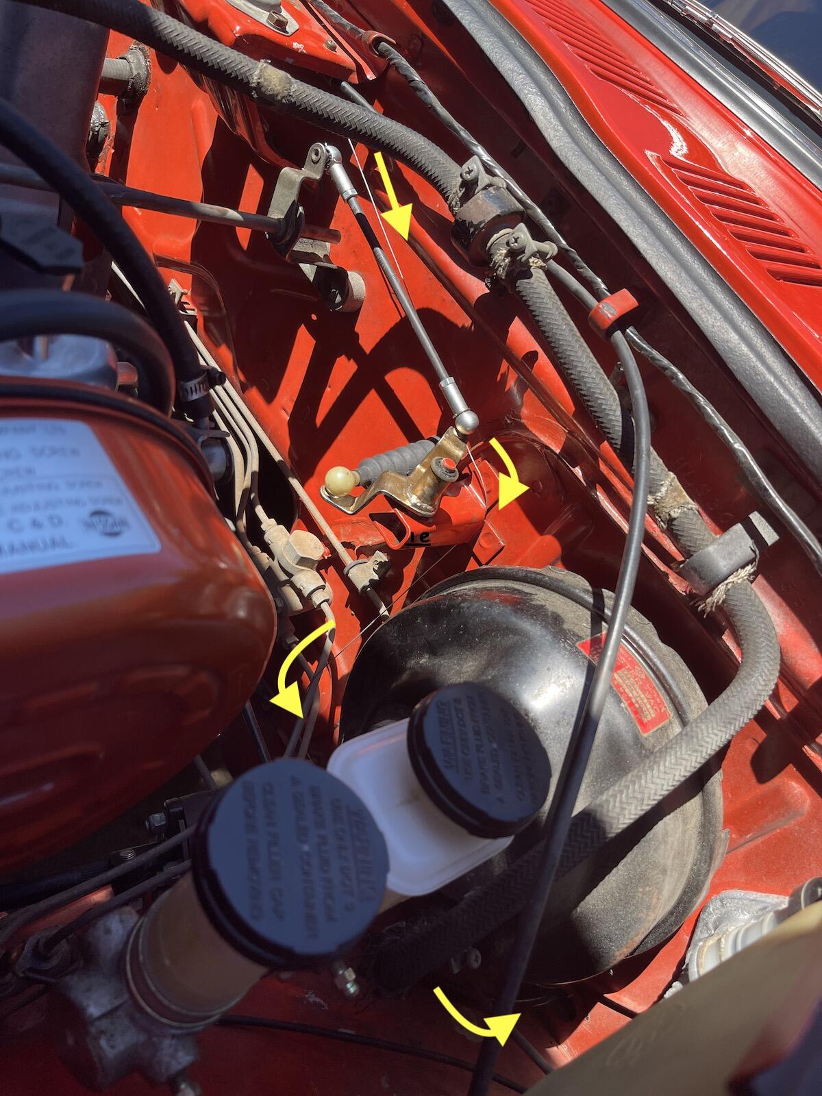
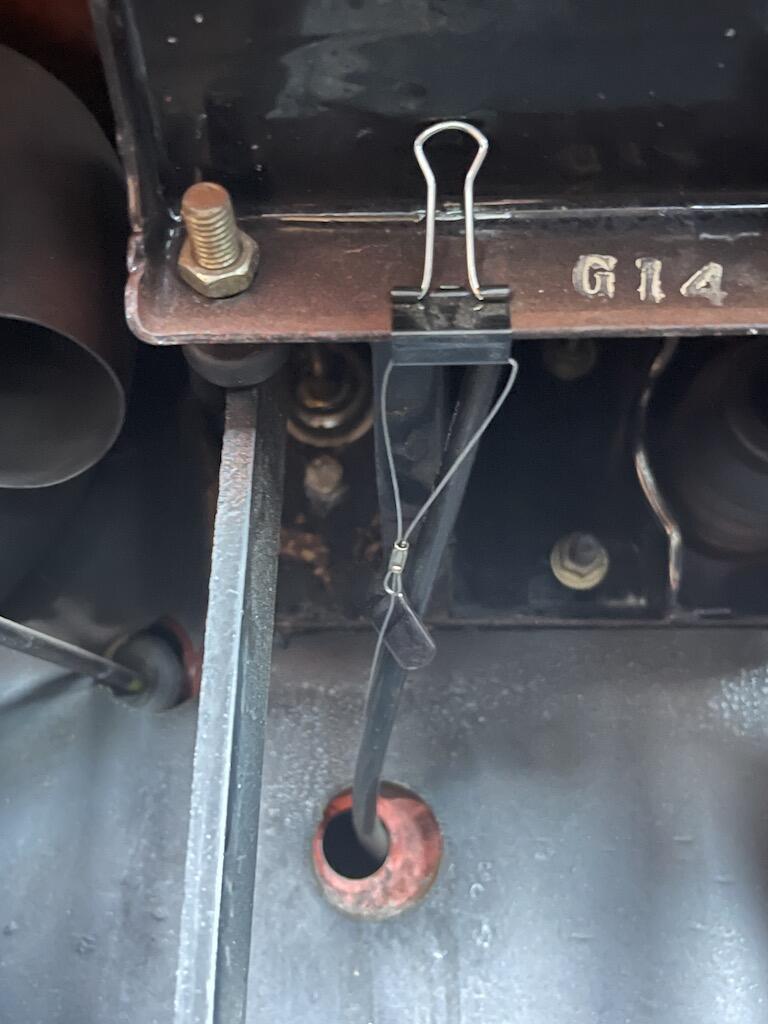
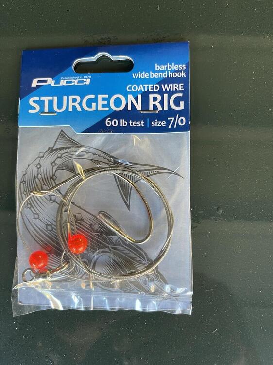
Last night I tried popping my hood open, with no luck. I figured I'd have to get it up in the air today and try prying the latch as mentioned in many other threads. But, somehow it did open, luckily. So while removing and cleaning the hood latch, checking the cable, I decided to add an emergency cable, just in case the original fails. First I bought a $2 hook and wire leader from Walmart, 60 lb test, about 34" long, and removed hook and beads. . Drilled an 1/8" hole in the top of the swiveling cable end connector, on the firewall side so it won't bind up with real cable. Fed the small cable loop up through the hole, then big loop through small loop. Attached factory cable and reinstalled latch. Fed new cable to throttle linkage bracket, down the inside of bracket, around brake lines so it wouldn't wedge into something, over to speedometer hole, and inside. Used small binder clip to clamp end of cable to clutch/brake pedal frame. Looks like I'm missing the speedo hole grommet. Anyway, it works great. Hopefully I'll never have to use it, but it's there if the occasion arises.


- 1 reply
-
- 5
-

-

-