pogden
Free Member
-
Joined
-
Last visited
Everything posted by pogden
-
I bought it on eBay, yes, and no, it wasn’t very expensive. I believe it was from Newark Auto. It fits very well, and seems to be well made. My only complaint is the lack of slits in the rear piece for cargo straps. I can add photos if you are interested. Sent from my iPad using Tapatalk Pro
-
I bought it on eBay, yes, and no, it wasn’t very expensive. I believe it was from Newark Auto. It fits very well, and seems to be well made. My only complaint is the lack of slits in the rear piece for cargo straps. I can add photos if you are interested. Sent from my iPad using Tapatalk Pro
-
I used various sizes of adhesive-backed insulation strips from the hardware store. They are sold in coils and should be with the door and window insulation stuff. Some worked better than others - the main problem I had was than some of them had crappy adhesive. Overall, it worked fine. Sent from my iPad using Tapatalk Pro
-
With my 76 280Z on stands under the FSM-specified support points (as show in Zed’s post), and with the engine, transmission, interior (including seats and dash) and front undercarriage out, it was easy to tilt the car back off of the front stands. My point is that the FSM support points may be focused mainly on chassis strength and not on balance shift due to major disassembly of heavy parts. As Zed said, you will probably be okay (as long as you don’t lift the rear or sit on the front while the suspension and tank are out), but it could not hurt to throw a bottle jack or something under the front crossmember just to be safe. Sent from my iPad using Tapatalk Pro
-
I laid my flat, in the sun, on the patio. It flattened quickly (a couple of hours, I guess), but not completely. It will finish flattening in place in your Z.
-
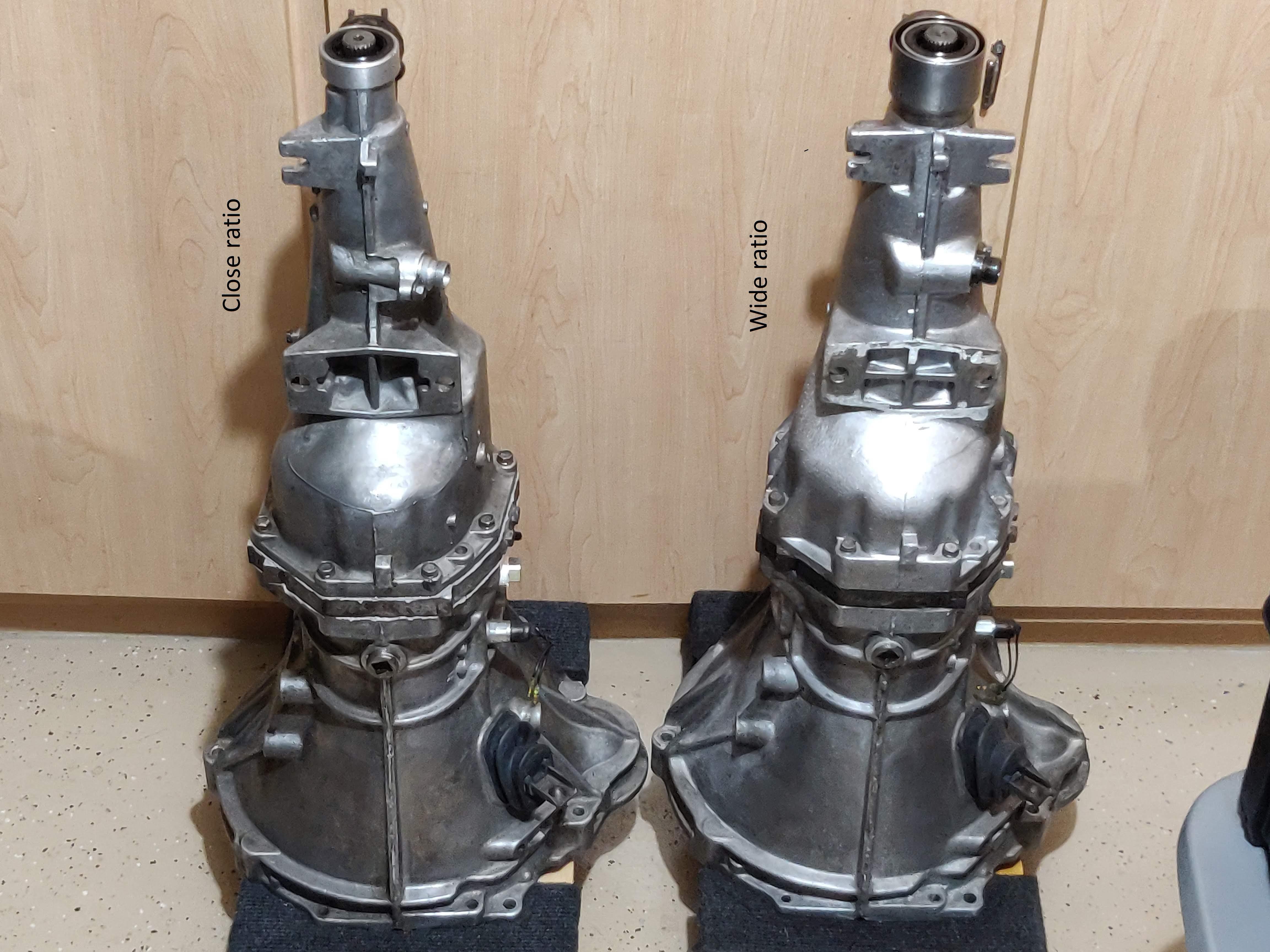
@L.Flores, yours looks like a close ratio gearbox to me, though your bell housing does look more like the one from my wide ratio. It is possible that yours (or mine) was at one point rebuilt and reassembled with a bell housing from a different year, or (more likely, IMO) they were just assembled at the factory with bell housings that came from different castings. I think all of the relevant changes between the early (wide ratio) and later (close ratio) boxes were internal or in the rear extension.
-
Thanks, Chas. I just might be able to fix this then - I also ordered the large roller bearings (the ones not included in the rebuild kit, for some reason). What you say about the baulk rings makes sense, but I'll probably replace them anyway (cuz I have 'em). But I'll give the old ones a good inspection first.
-
My wide ratio gearbox (the one in the pictures at the top of this thread) pops out of 2nd gear. Not always when upshifting, but always when downshifting. I've been reading everything I can on this site about overhauling one of these things, and I am going to give it a shot. I just received the rebuild kit from Rock Auto, which seems to be the exact same one sold by other places as described in @zKars's lengthy FS5W71B Rebuild Thread, and it was <$60. I also ordered a bunch of other small parts (seals, main shaft and countershaft nuts, detent springs/balls, oil gutter, Torx screws) that I might need from Courtesy Nissan. I did not order any of the big parts (gear sets, shafts) - I understand that many of those are NLA. Regrading slipping out of gear, I have no idea why it's doing that, but I hope to find out. My *guess* is either a problem with the 1-2 baulk ring or maybe one of the detent springs. Thanksgiving project, I hope.
-
I understood the original question to be "If both engine and transmission are out, is it better to install the engine and transmission as a unit, or drop the engine in first and then the transmission". In that case I would always do them as a unit unless something (maneuvering room, availability of a leveler) prevents it. If only the engine or the transmission needs to be removed, then yeah, only remove that - no need to remove both just to service one.
-
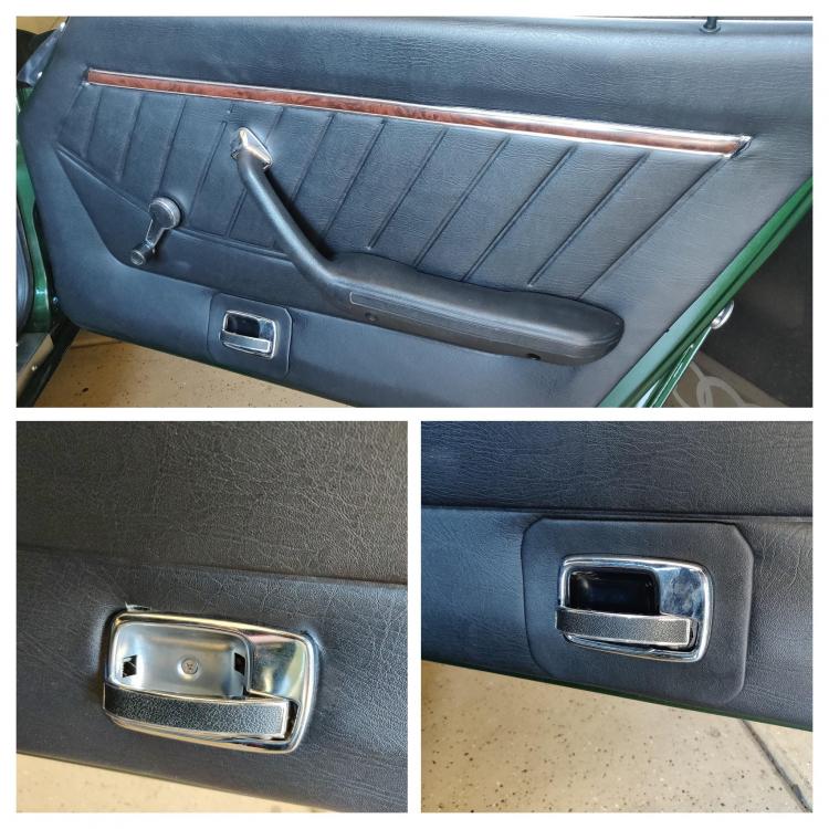
I am really happy to hear that Hung Vu will be producing 75/76 (and presumably 74) door panels. I've never understood why there are aftermarket ones available for 77/78 but not 74-76 - I always ASSume that the hard part is shaping and producing the card itself and that it could be adapted for either (and maybe even for the 70-73), but I guess if it were that easy someone would have done it by now. FWIW, several years ago I did manage to find a set of aftermarket panels for my 76. They are not quite right (NONE of the holes are where they should be, and they are actually a little too short front-to-back), but the shape and fabric were way better than my originals. The biggest problem was the hole for the release handle which was about half an inch too far forward. I made a little rectangular trim piece to cover the gap around the handle. Not really happy with the end result, so I'll be keeping an eye open for Hung Vu's offering.
-
It is, Chuck. I hope Ford tested it in an F-250 or a Focus and not a Crown Vic! Sent from my iPad using Tapatalk Pro
-
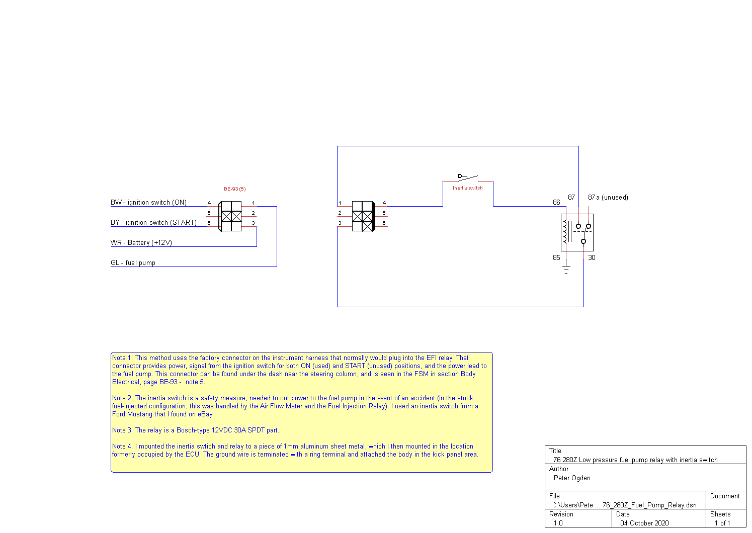
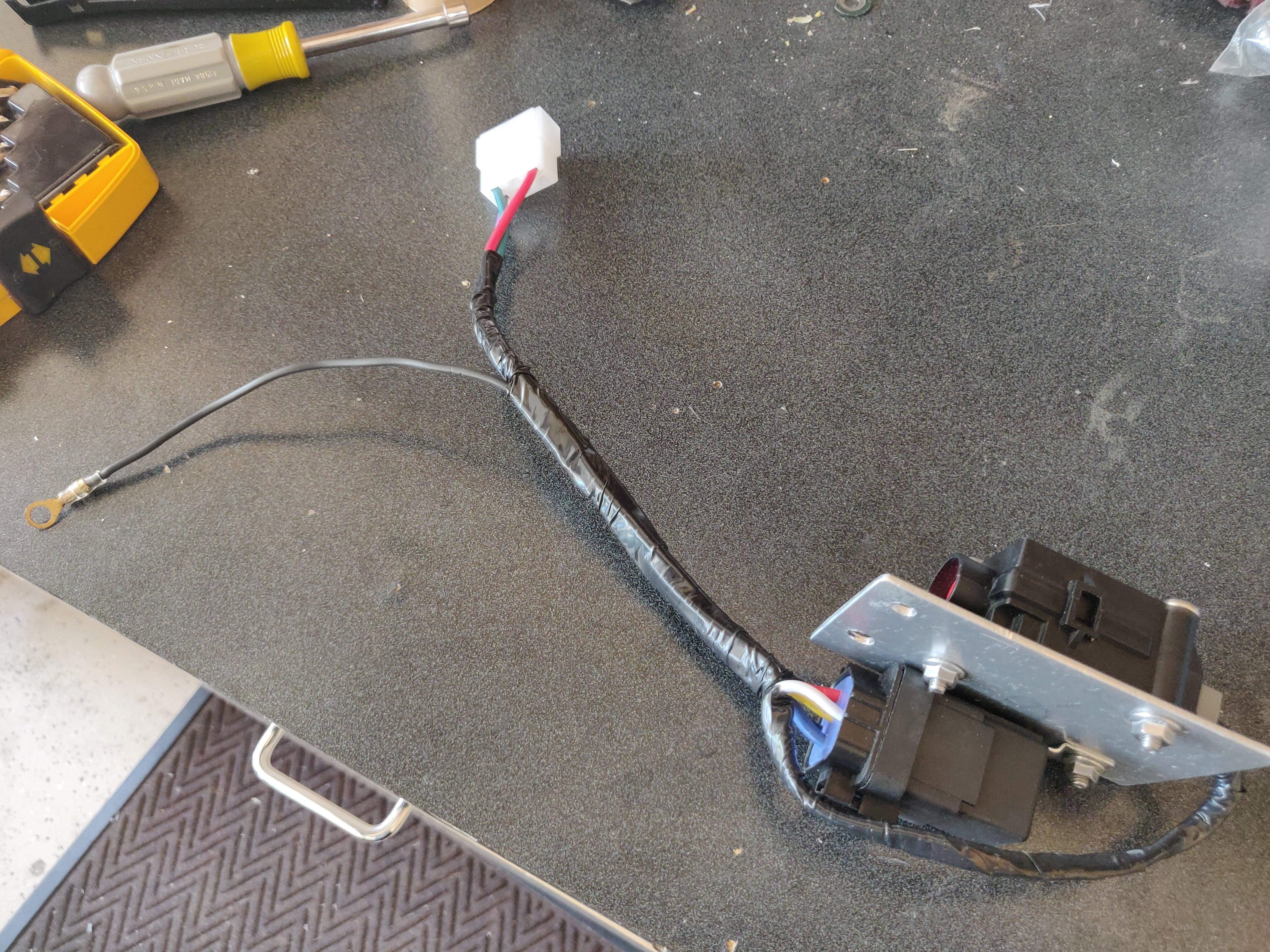
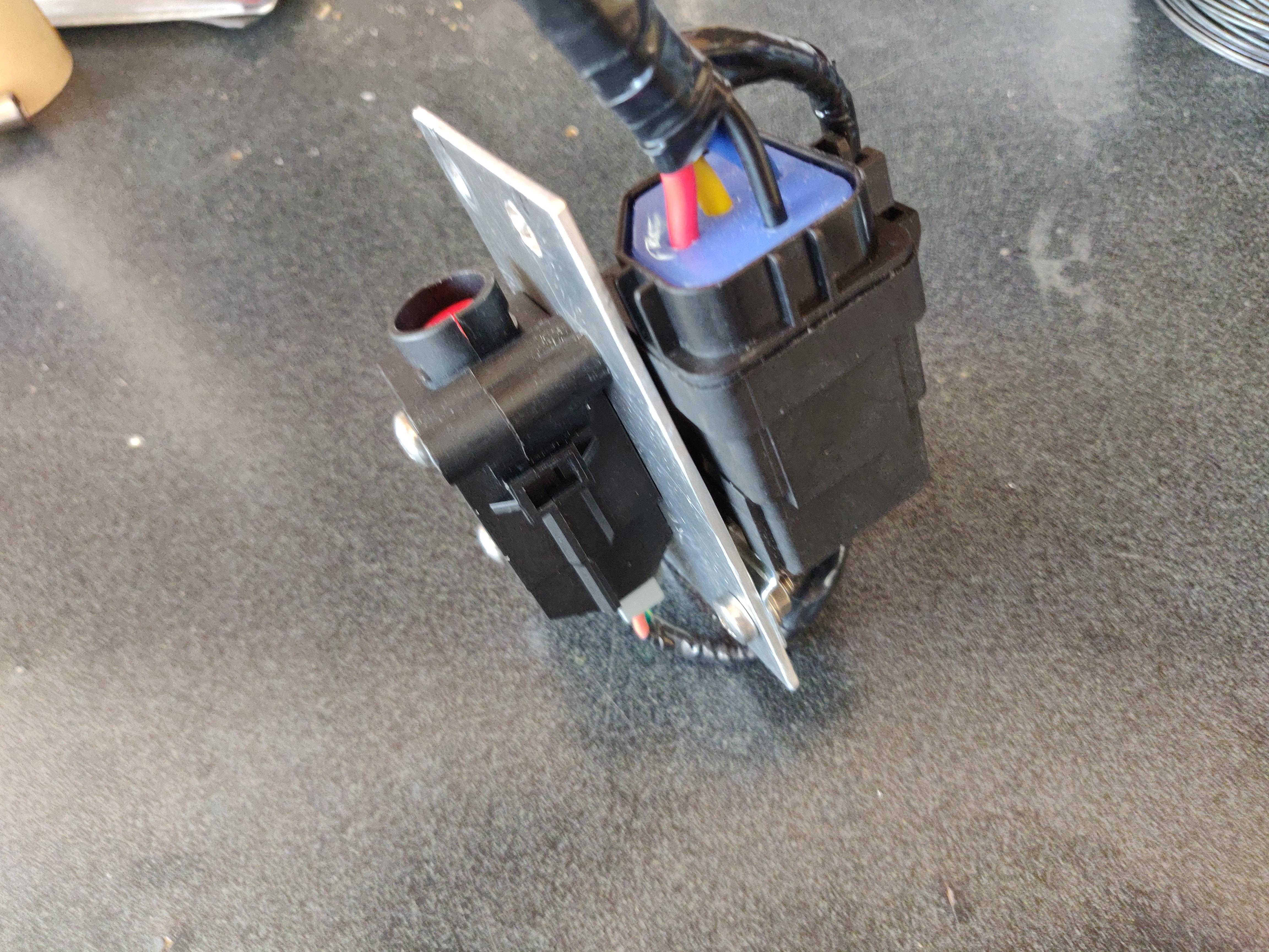
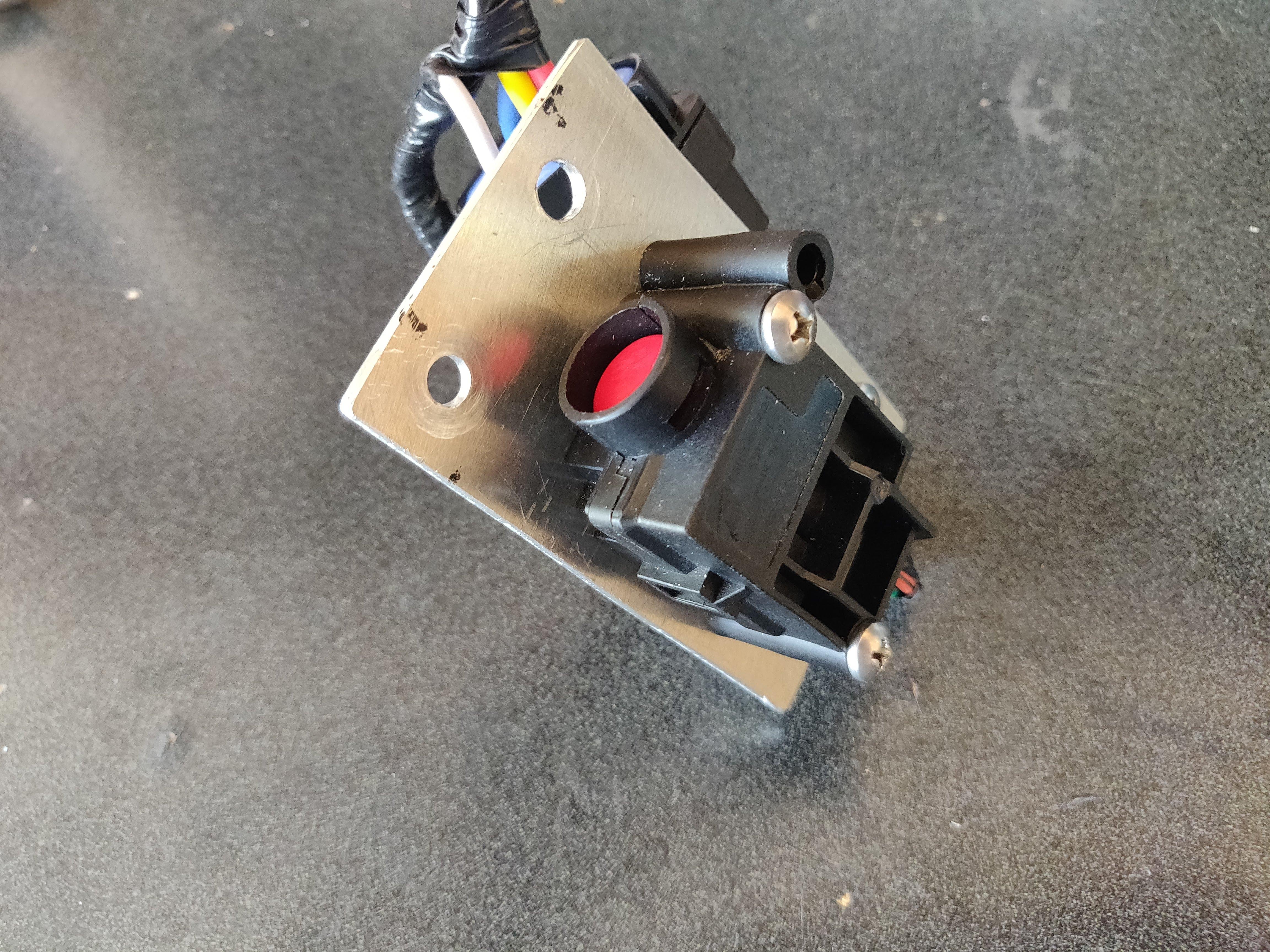
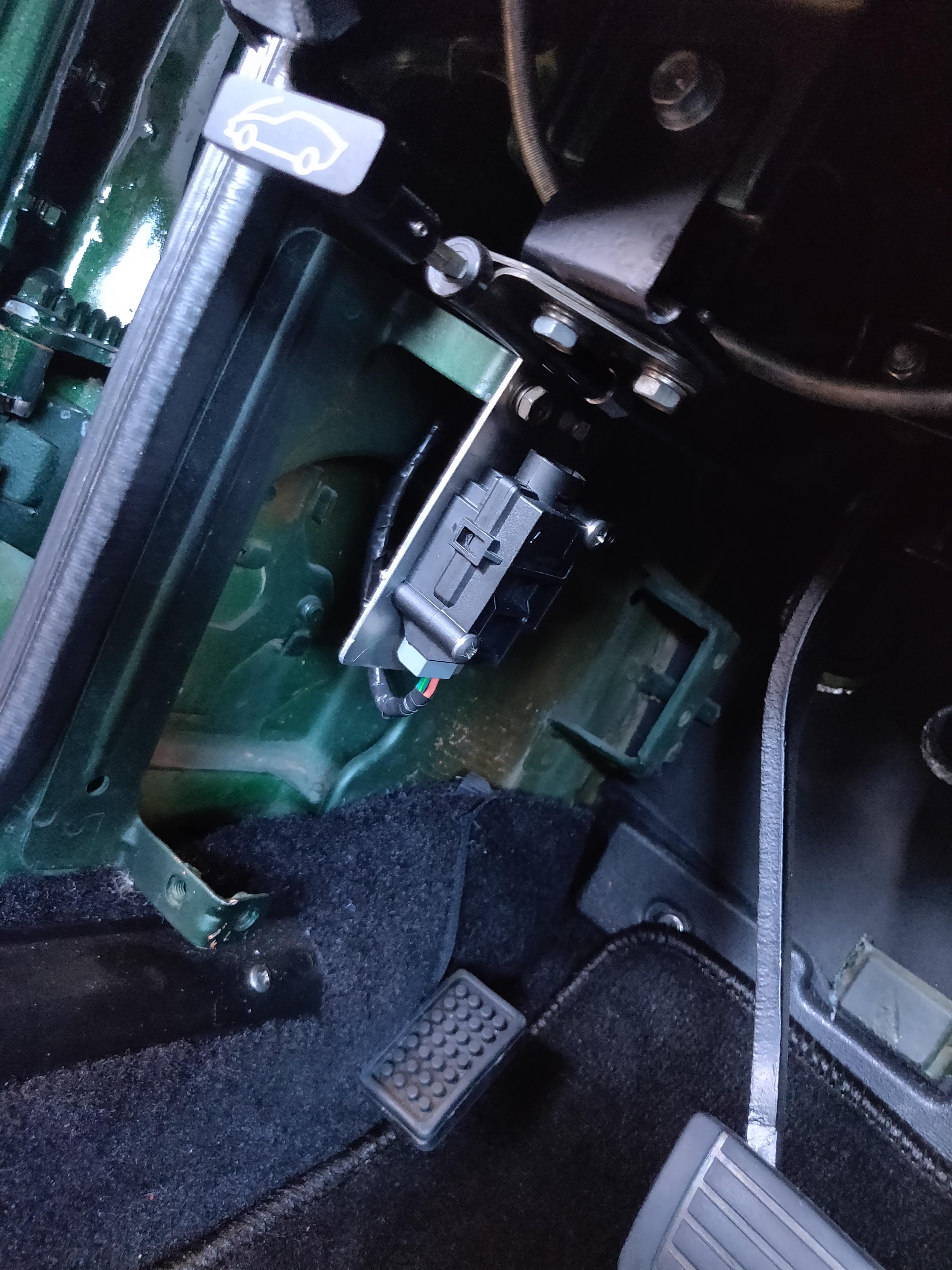
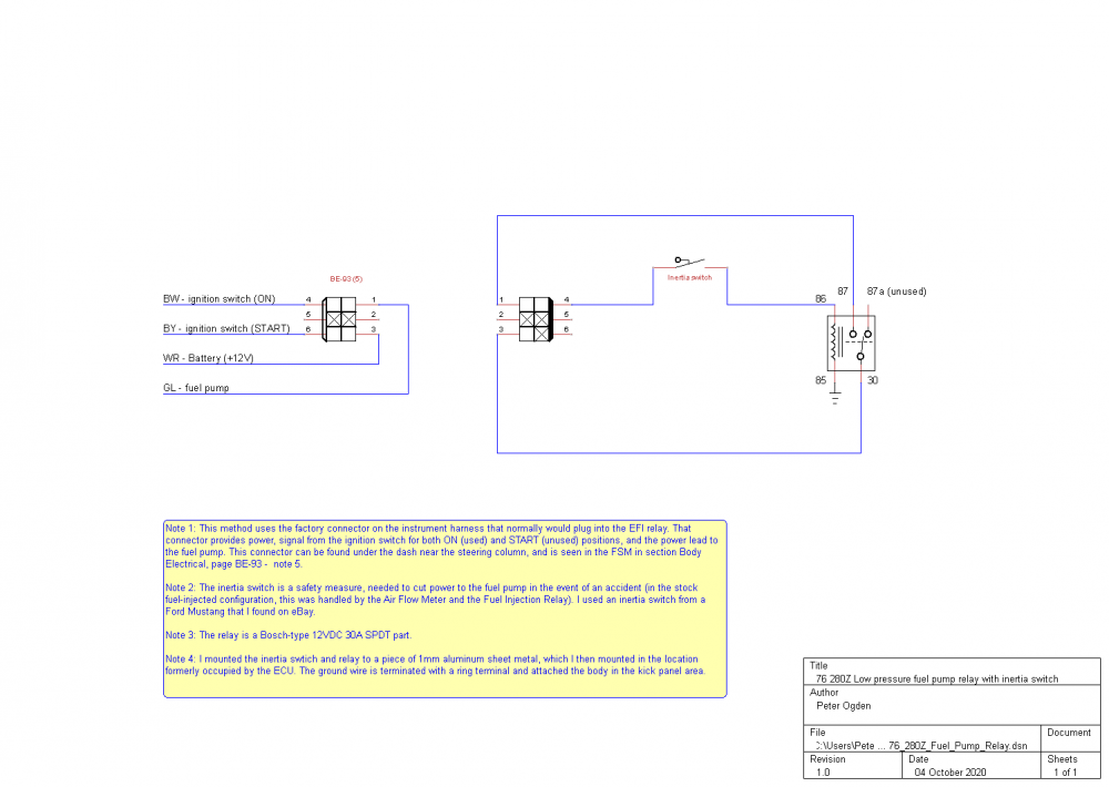
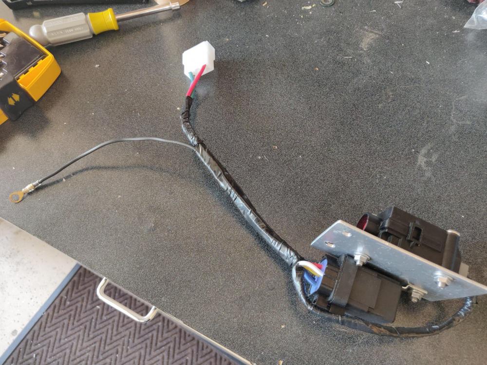
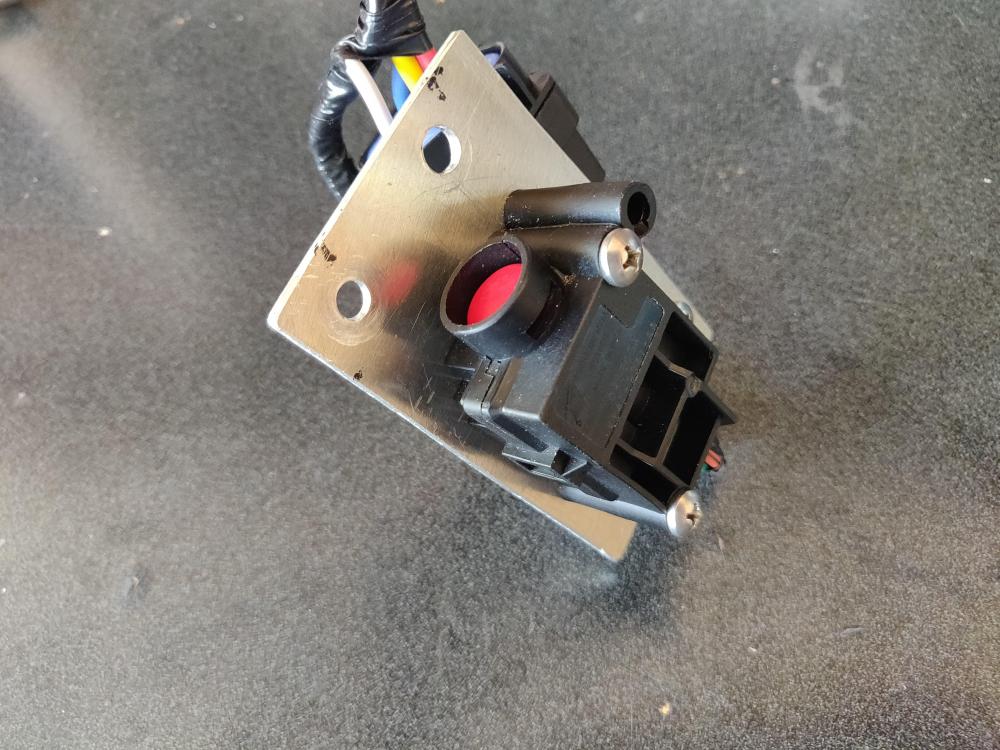
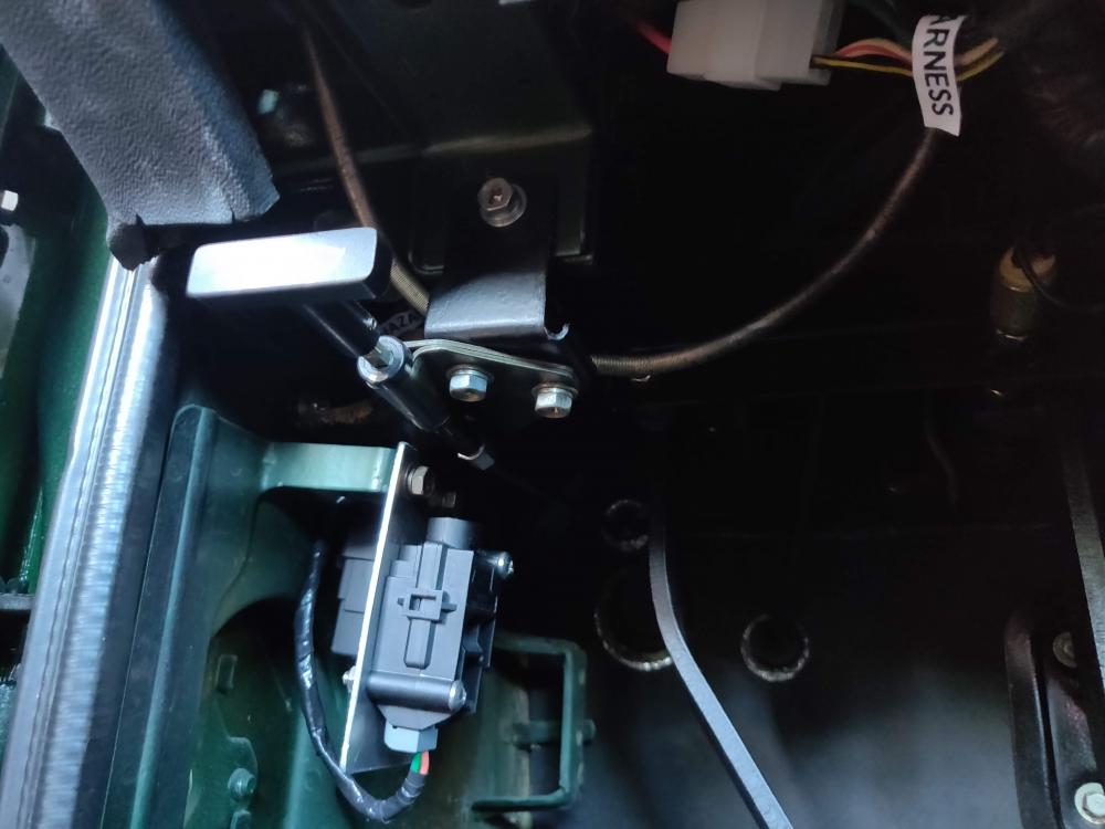
I have a 1976 280Z that was converted to SU carbs by the previous owner. The mechanical fuel pump was crap, so I replaced it with a GMB part which didn't seem to work very well. I replaced that with another GMB pump which seems to work fine. I am aware that some have reported problems with them, so I also installed a NISMO electric pump. In reading on this site about how to wire this up I saw lots of advice about adding an inertia switch for safety. From the FSM and wiring diagram I also learned that the factory fuel pump in my car was controlled by the fuel injection relay, which had been deleted long ago from my car. This article describes one pretty clean way of wiring in a relay and an inertia switch to provide power to a low-pressure electric fuel pump in a carb-converted 280Z. Background: In the 280Z the fuel injection relay is actually two relays packaged together: the EFI bible refers to these as the Power Relay and the Fuel Pump relay. When the ignition switch is in the ON position, the power relay sends sends power to the fuel injection system (ECU, fuel injectors, AFM); the fuel pump relay sends current to ... yep, the fuel pump. The current sent to the AFM doesn't power the AFM; rather, the AFM closes a set of contacts when the engine is running and air is flowing, and it opens those contacts when the engine is off. The current required to operate the fuel pump relay runs through those AFM contacts so that the fuel pump relay closes only when the engine is running and air is flowing. If the engine stops, the AFM contacts are opened and so is the fuel pump relay. It's a little more complicated than this (related to how the Start position of the ignition switch sort of overrides all of this so that the fuel pump can run in order to start the engine), but that's not really important for this discussion - I want the fuel pump to run when the ignition is in the ON or START position, unless I've been in an accident. It turns out, there's an easy way to do this. The connector that (formerly) ran to the Fuel Injection relay is part of the instrument harness and is found under the dash by the steering column. I just replaced the female 6-pin connector (only 4 pins are used) with a similar one from Vintage Connections and then wired the male part to the Ford-type inertia switch and Bosch-type 12VAC 30A relay as shown in the diagram and pictures below. I just mounted the relay and switch to a piece of 2mil aluminum plate, and mounted the whole thing by where the ECU was located. It seems to work: the fuel pump comes on with the key in the ON position, and if I tap (well, smack) the inertia switch to get it to open, the fuel pump turns off. I haven't driven it enough yet to know whether the inertia switch will "break" when I don't want it to (going over bumps, etc.), but it's easily reachable from the drivers seat.


-
Very good explanation, Captain. I agree that his should be a sticky. Sent from my iPad using Tapatalk Pro
-
Cell phone cameras have improved quite a bit in half a decade, eh? :-) Sent from my iPad using Tapatalk Pro
-
The paint looks fantastic - nicely done, man. Sent from my iPad using Tapatalk Pro
-
I’ve done it both ways a few times now, but believe putting the engine and transmission in as unit is easiest. I can imagine that just a small difference in the geometry of one hoist/leveler setup vs. another could make an annoyingly big difference, but here’s what worked well for me: Jack up the rear of the car and set it on jack stands (lowest level, about 12in from the floor to the top of the stand. Make sure you leave enough room in front of the Z for the full length of the engine+transmission hanging from the hoist. Aside: My son and I (mostly my son) devised this approach to minimize the vertical clearance needed (my garage ceiling is 10ft) while leaving room under the car to finagle the transmission crossmember into place. It works perfectly. Put some folded towels over the core support and draped in front of the firewall from the cowl. Lubricate the screw threads on your engine leveler. Raise the engine+trans until the transmission clears the core support, then wheel it over the engine bay, centering it right-left as best you can. Using your leveler start tilting the whole thing back (transmission down) and raising the whole thing up so that the oil pan clears the core support. Between you and your helper, one keeps a hand on the tail of the transmission and steers the whole thing, the other guy manages the hoist (up/down, forward/back, tilt/level). Hoist man should be confident in his ability to lower the hoist at a slow rate and stop its decent - practice before this point can’t hurt. As the oil pan crosses the core support you will probably approach the backward-tilting limit of your hoist. As you lower it into the bay, start tilting it forward (transmission). Continue lowering, pushing, and tilting until the the engine is almost resting on the drivers side mount (it’s higher than the other one). Make sue the fore/aft tilt looks good compared to the engine brackets and mounts. At this point, it may be useful to loosen the engine brackets bit to make threading the bolts into the engine mounts easier. Put the bolts on the driver side first, then lower the engine a bit more so you can get the bolts on the passenger side. Getting all four transmission mount bolts threaded can be one of the most fiddly, annoying, swear-inducing things you can do on a Z (at least, on mine), but you WILL get them. Having your helper push tail piece of the transmission forward/back, in/out, up/down from under the Z can help. Once the front engine mount bolts are finger-tight, the transmission crossmember can be installed. Sent from my iPad using Tapatalk Pro
-
@dutchzcarguy, thanks for adding the detail. I knew that Euro-market 240Z's were available with 5-speeds, but the specifics you added here are great. And I'll edit my original post to make it clear that I'm in the US, and my comments are based on what I've seen/heard about Z's here. @zKars, the wide ratio gearbox in my photos came out of a 280ZX - I believe it was a 1979 - I removed i myself (with help from my local Z buddy @Randalla). I'm honestly not certain of the origin of the close ratio box - I bought in on eBay - but it was said to be out of a 1983 280ZX. It is my understanding that the term "close ratio" refers to the difference between 2nd and 3rd. Looking at your table, either of the two later model 5-speeds would be considered "close ratio", right?
-
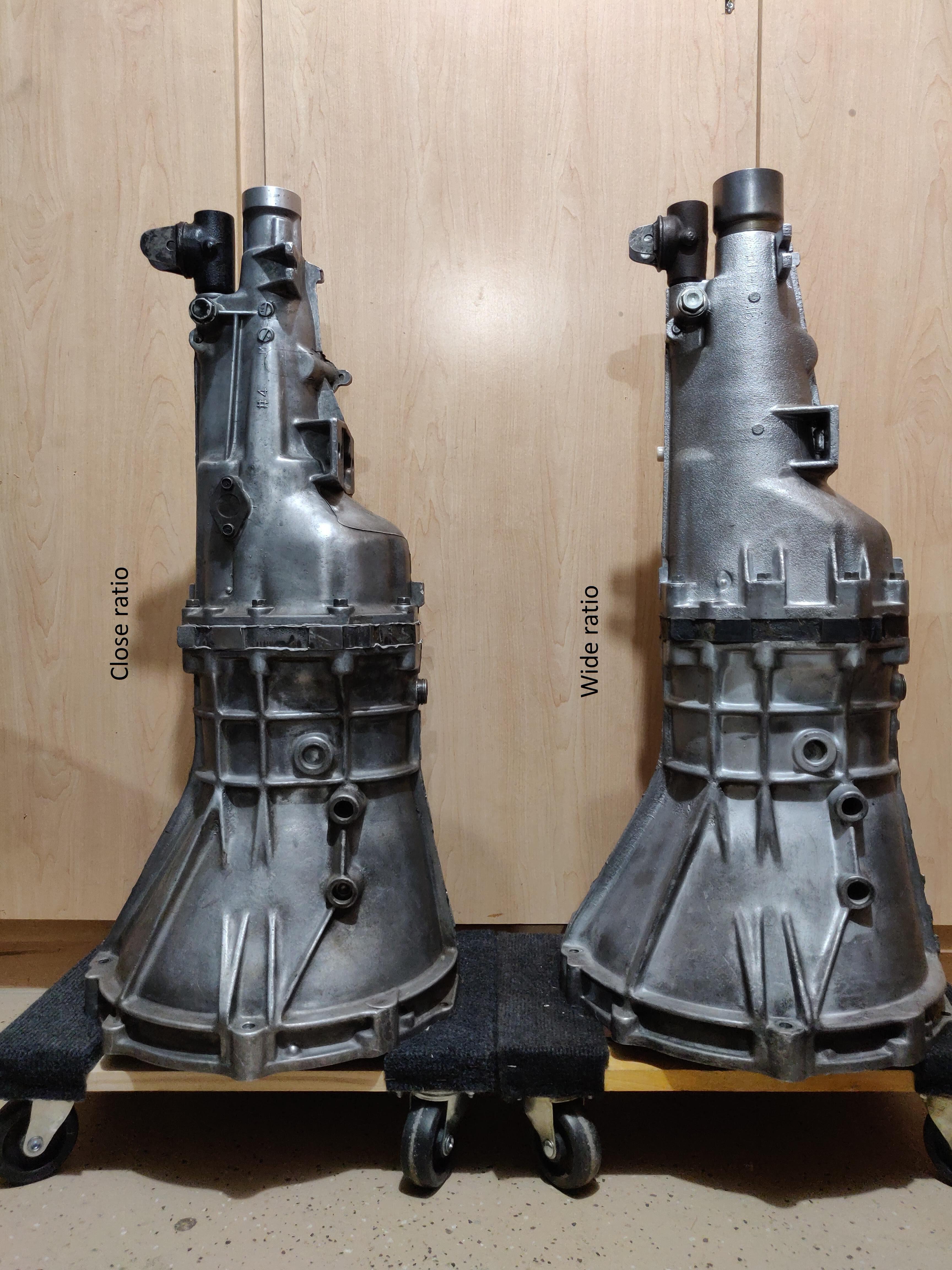
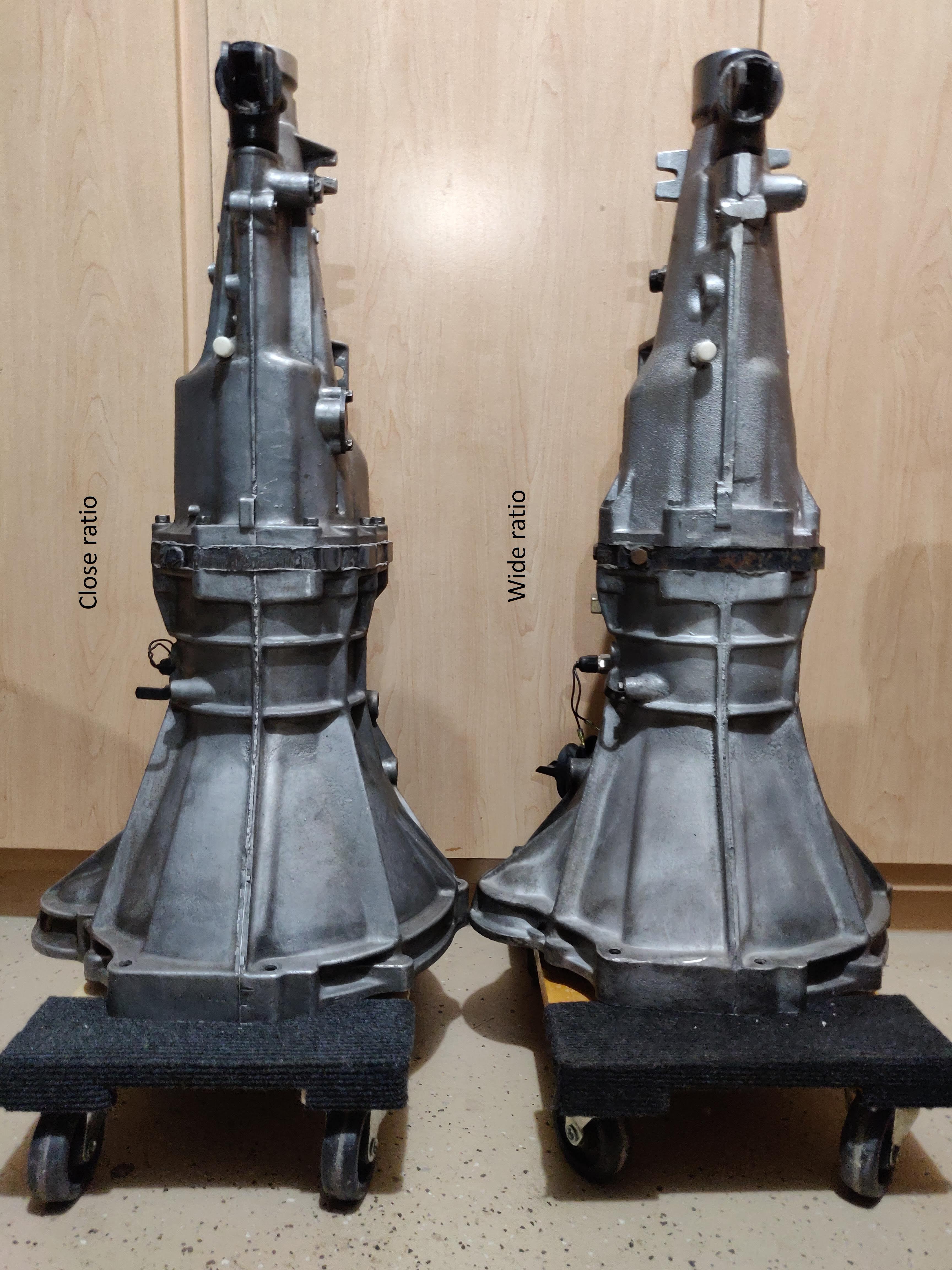
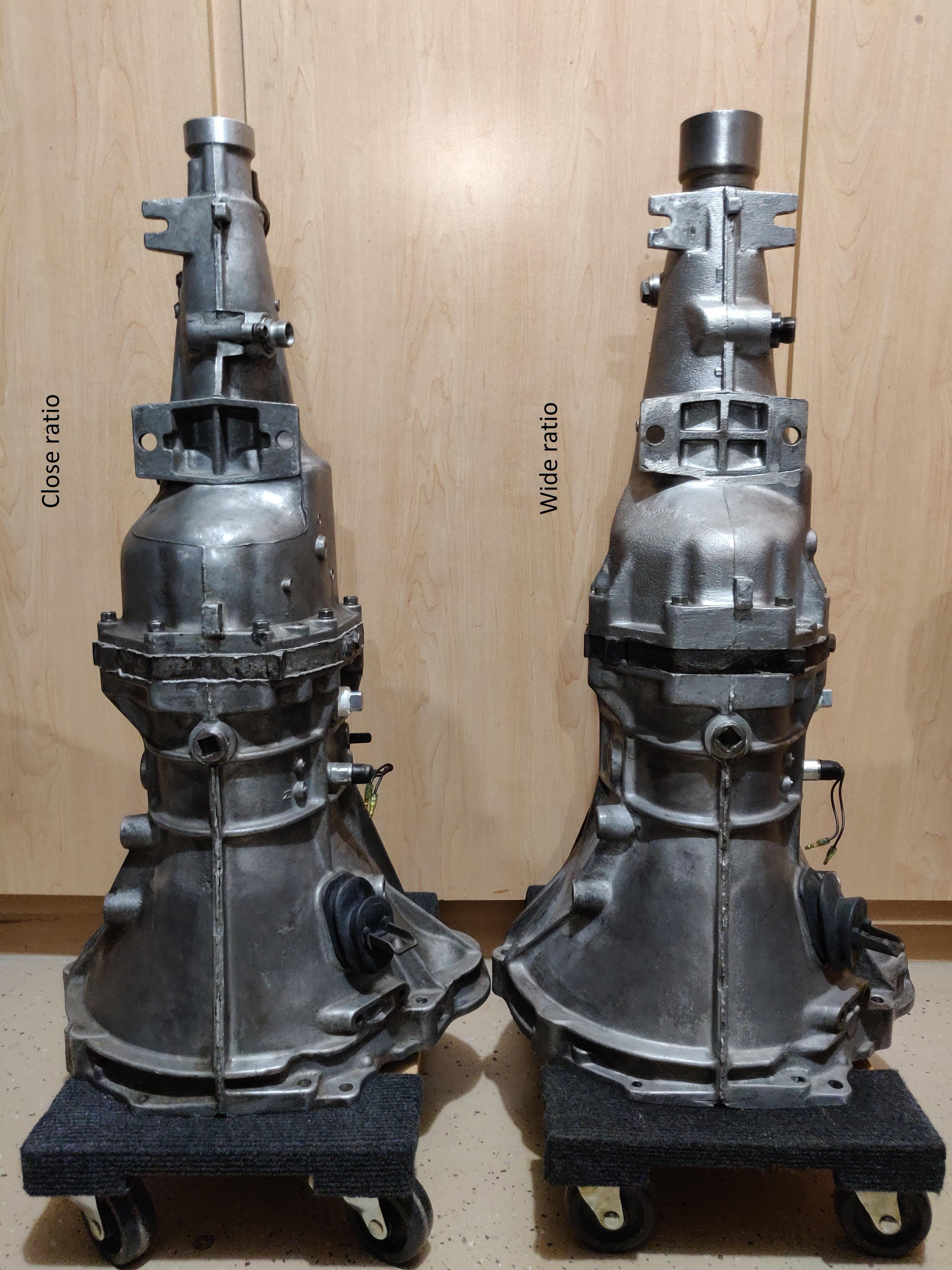
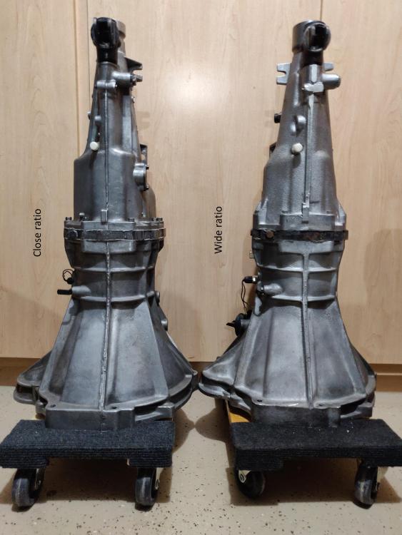
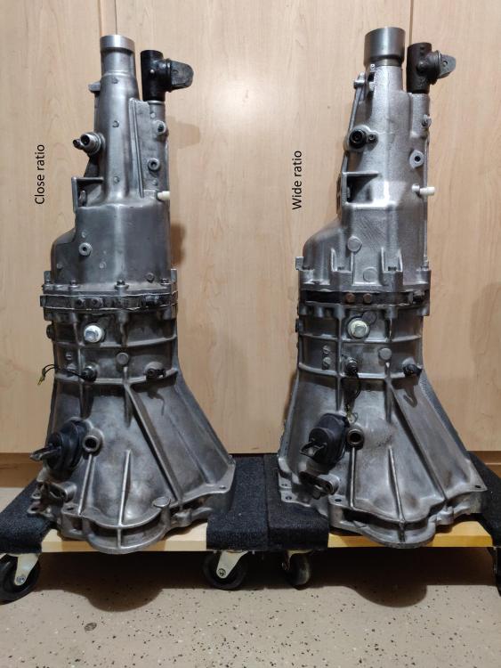
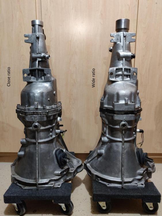
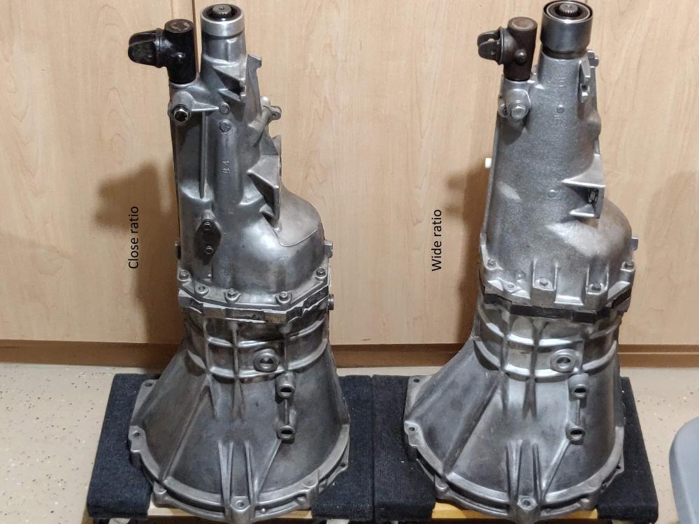
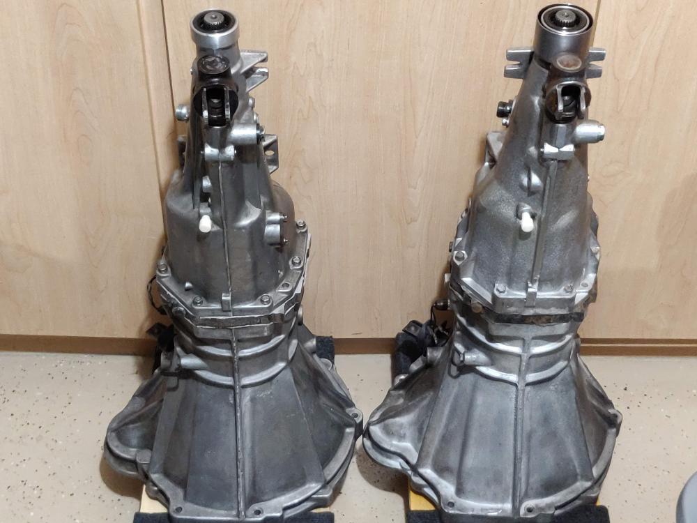
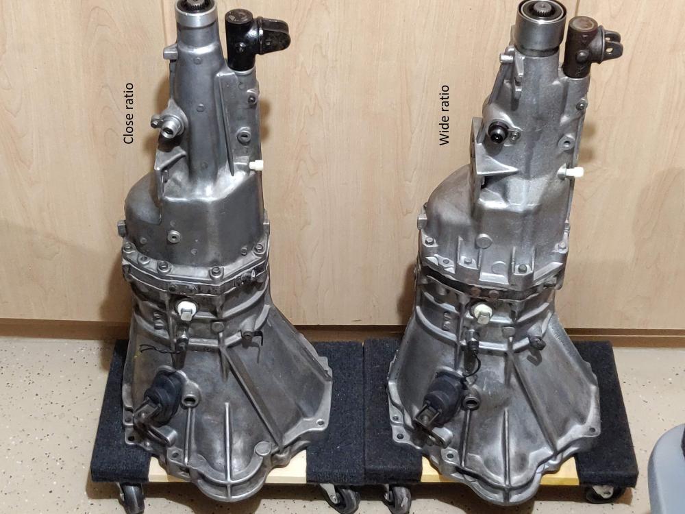
A few years ago when I was looking for a 5-speed transmission for my 1976 280Z project, I searched and searched for photos of the early ("wide ratio") and later ("close ratio") versions side-by-side. I never really found any, but I did acquire one of each, and thought I'd post pictures of them for easy comparison. The main things to notice are all on the rear extension housing: The wide ratio gearbox has two exhaust hanger ears on the rear extension housing, the close ratio has only one (on the driver's side). The wide ratio has a dust collar/shroud surrounding the end of the tail piece, the close ratio does not. The close ratio box has a cover for the reverse loickout mechanism on the left side, the wide ratio does not. On the close ratio, the screw that secures the speedometer drive assembly to the rear extension housing is located at 6 o'clock (toward the bottom of the transmission), on the wide ratio the screw is at 12 o'clock (toward the top). The striking rod guide (where the shift lever attaches) is slightly wider/taller on the close ratio than on the wide ratio. Overall, the wide ratio rear extension housing has s smoother, more rounded appearance.


-
I guess the spinning screws were probably over-tightened, which either stripped the plastic threads on the housing or cracked the the plastic around the holes. Either way, the friction between the housing and the screws is probably enough to hold it somewhat securely, but maybe you can gently wiggle or pry the housing back away from the panel, at lease enough to grab the screws with pliers and wiggle/twist them out? When repairing the holes, I would be tempted to use a tooth pick or two liberally coated with expoxy to fill the holes, then drill them out with a bit that is slightly smaller in diameter than the screws, giving them something to bite into.
-
I too can confirm Zed’s 92mm number. I just replaced my clutch and it works great with the “long” sleeve that was already on the car. Glad you replaced the pilot bushing, the old one looked pretty far gone. Sent from my iPad using Tapatalk Pro
-
^ This. Every trimmer/upholsterer I’ve talked to is reluctant to try refurbishing Z door panels that don’t have good (not wavy and water-damaged) Masonite cards to begin with. They just don’t think they can restore the panel itself, and therefore the end result will be a wavy, deformed panel nicely covered in view vinyl. I’ve seen reproduction 240Z panels, and 77-78 280Z panels, it nobody seems to produce panels for 260Z and early 280Z. 4-5 years ago I did find an aftermarket set for my 76 from a seller in BC, and I bought them. Years later, when I was ready to fit them, I found that not a single cutout or hole was in the right place (except for the lock knob). Canadian Z’s must be an inch shorter than the ones sent to the US ... Sent from my iPad using Tapatalk Pro
-
I am by no means an expert, but here is my recent experience that sounds similar to yours. I am 5 years into the restoration of a 76 280Z that did not run when I bought it. I was told, by the PO, that it had been driven a couple of months before I bought it, but I don't know that to be true. I swapped the 4-speed for a rebuilt close-ratio 5-speed , but (like an idiot) I did not replace the clutch. The clutch disc was supposedly new, and to my untrained eye the pressure plate looked ok. Fast forward to a month ago when I got the car running for the first time. It was still on jackstands, so I decided to run it through the gears - no dice. It shifted fine with the engine off, but with it running it just wouldn't go into gear, and like you I didn't want to force it. I had recently replaced the master and slave cylinders, blown out the lines, added fluid, and bled the system. I checked the travel on the slave cylinder while a friend (and Z expert) pushed the clutch - it smoothly moved the clutch fork about an inch, maybe a bit more. My friend suggested double-clutching (clutch to the floor, back up, then back to the floor), and it actually worked. By double-clutching, I was able to shift through gears 1-5, though it wasn't exactly smooth. Reverse was still a no-go. The local consensus was a clutch problem, so I dropped the transmission and removed the clutch. I bought a new M-pact kit from ZCarSource (just down the street from me here in north Phoenix), installed it, and it shifts beautifully now. Having said that and just read EuorDat's and Zed's suggestions, it's possible my clutch disc was seized (i.e., not sliding along the splines of the input shaft) - I never thought of that. When I installed the new clutch, I followed the directions in the FSM - I carefully lubed the splines (with the little tube of purple lube supplied with the clutch kit), mated the disc to the splines and ensured it slid back and forth nicely, and wiped off the extra before bolting the clutch assembly to the flywheel. It's possible I either omitted this step or used the wrong lube when I first installed the 5-speed several years ago.
-
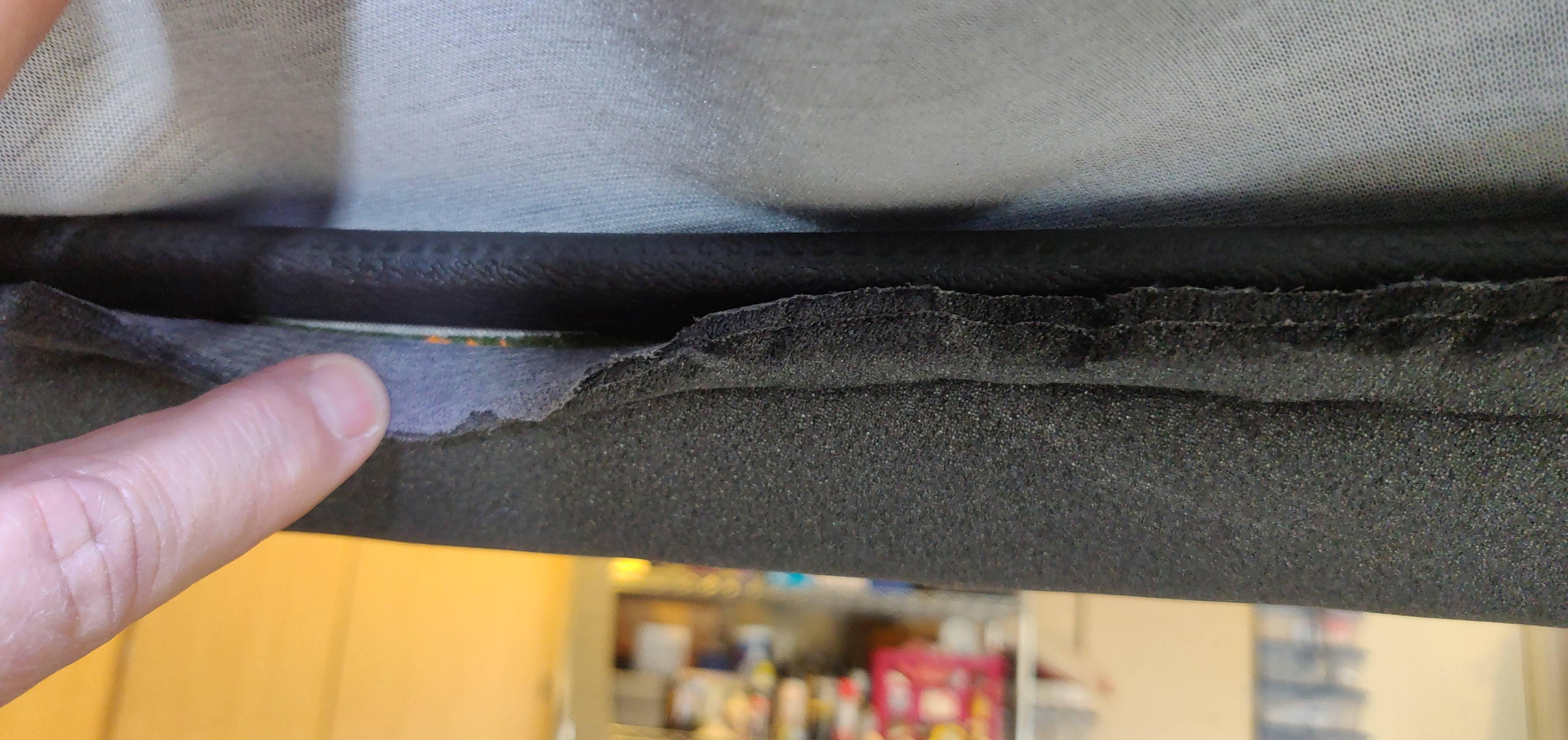
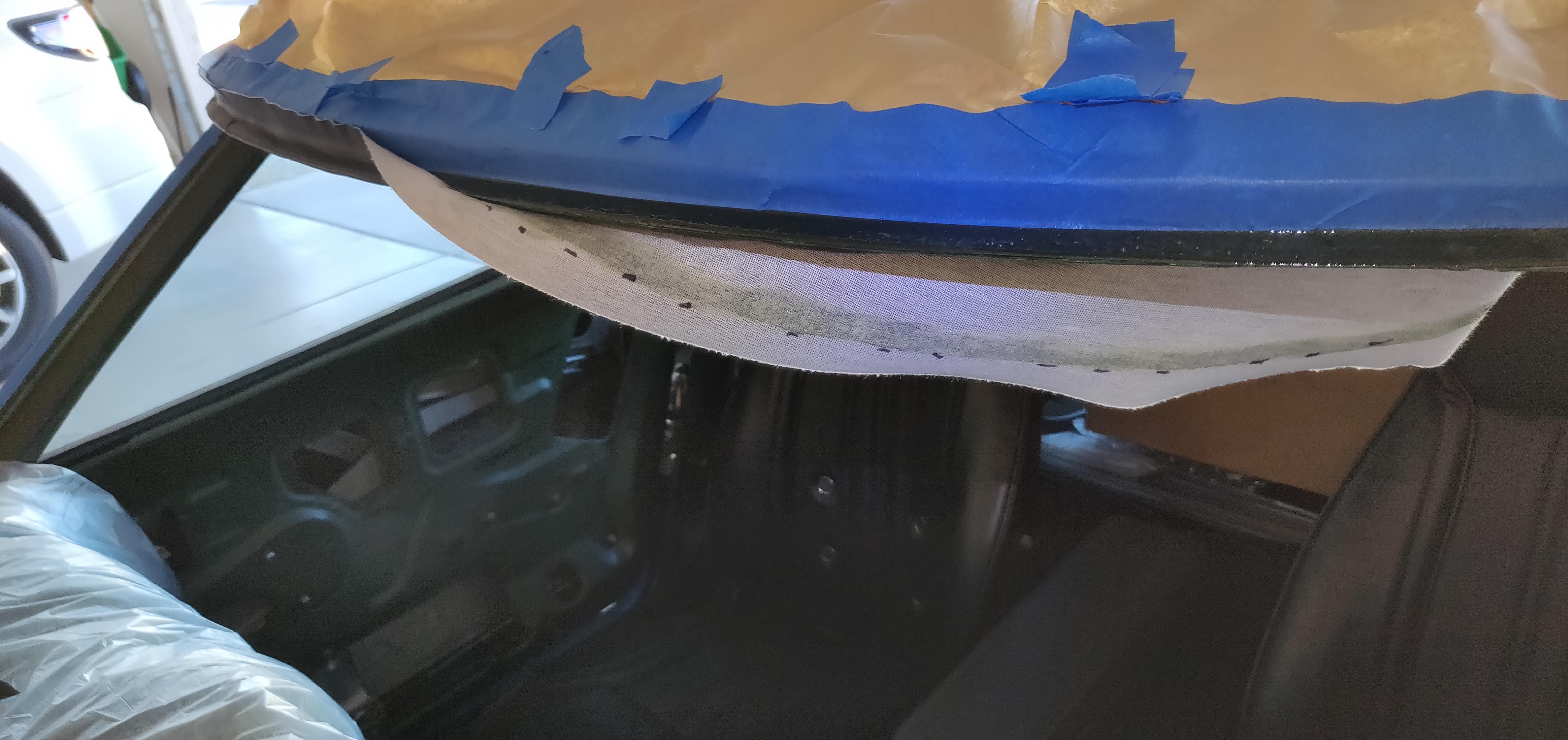
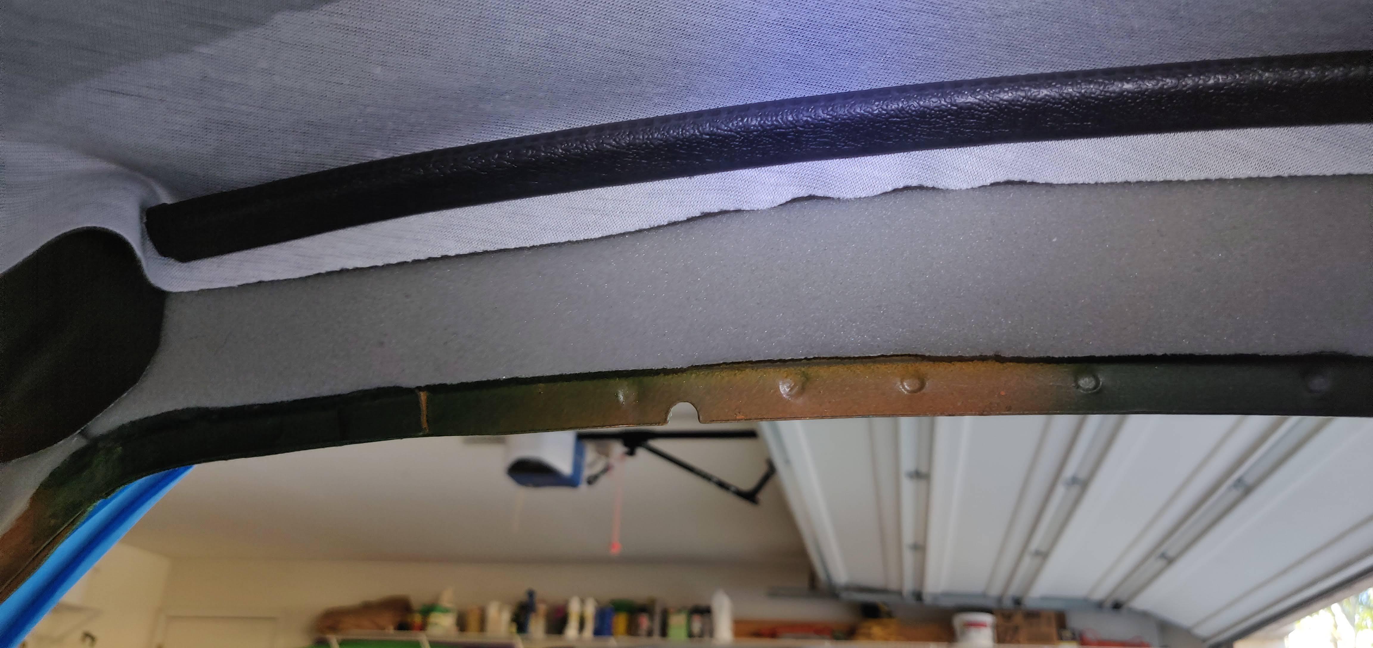
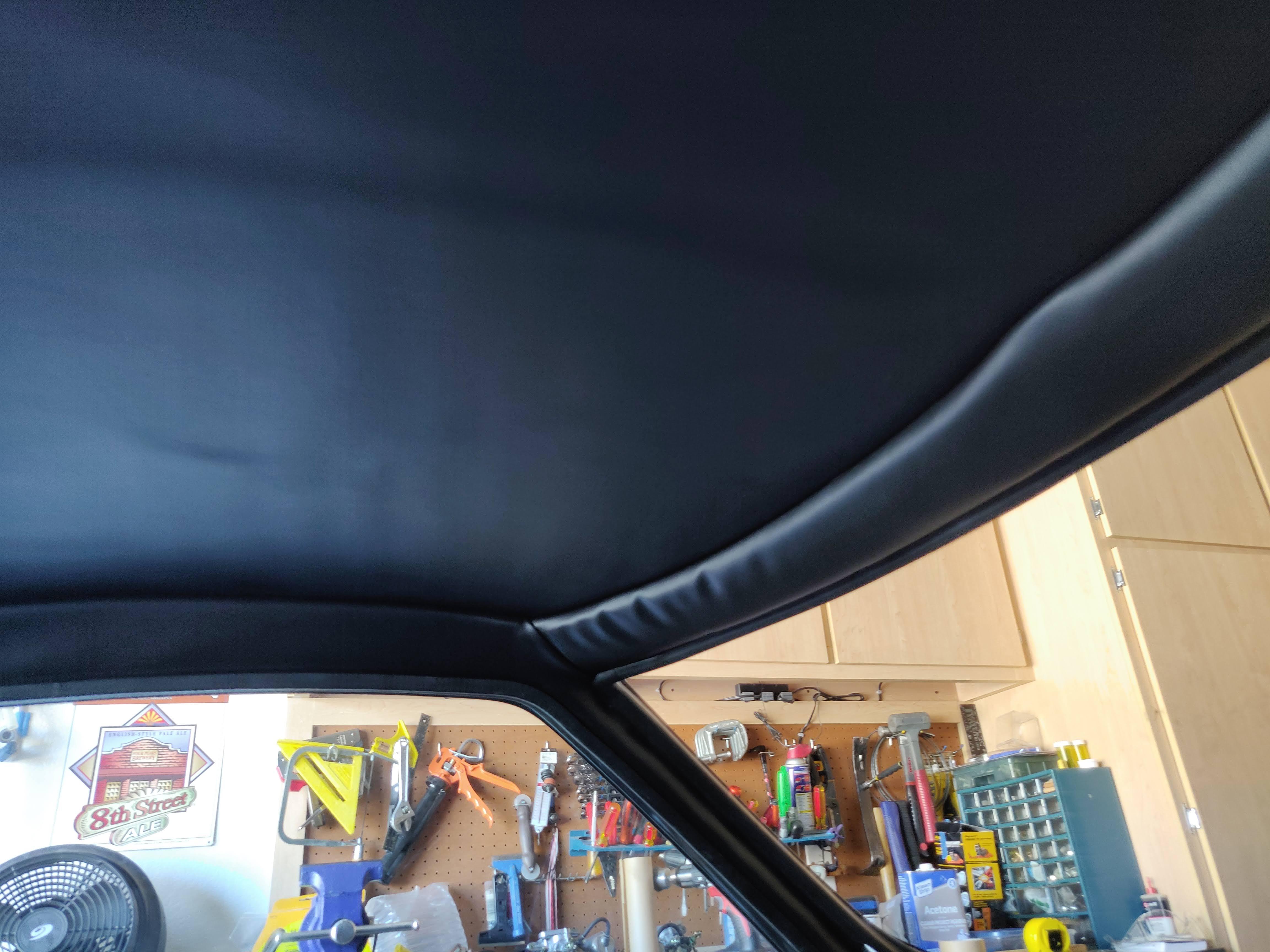
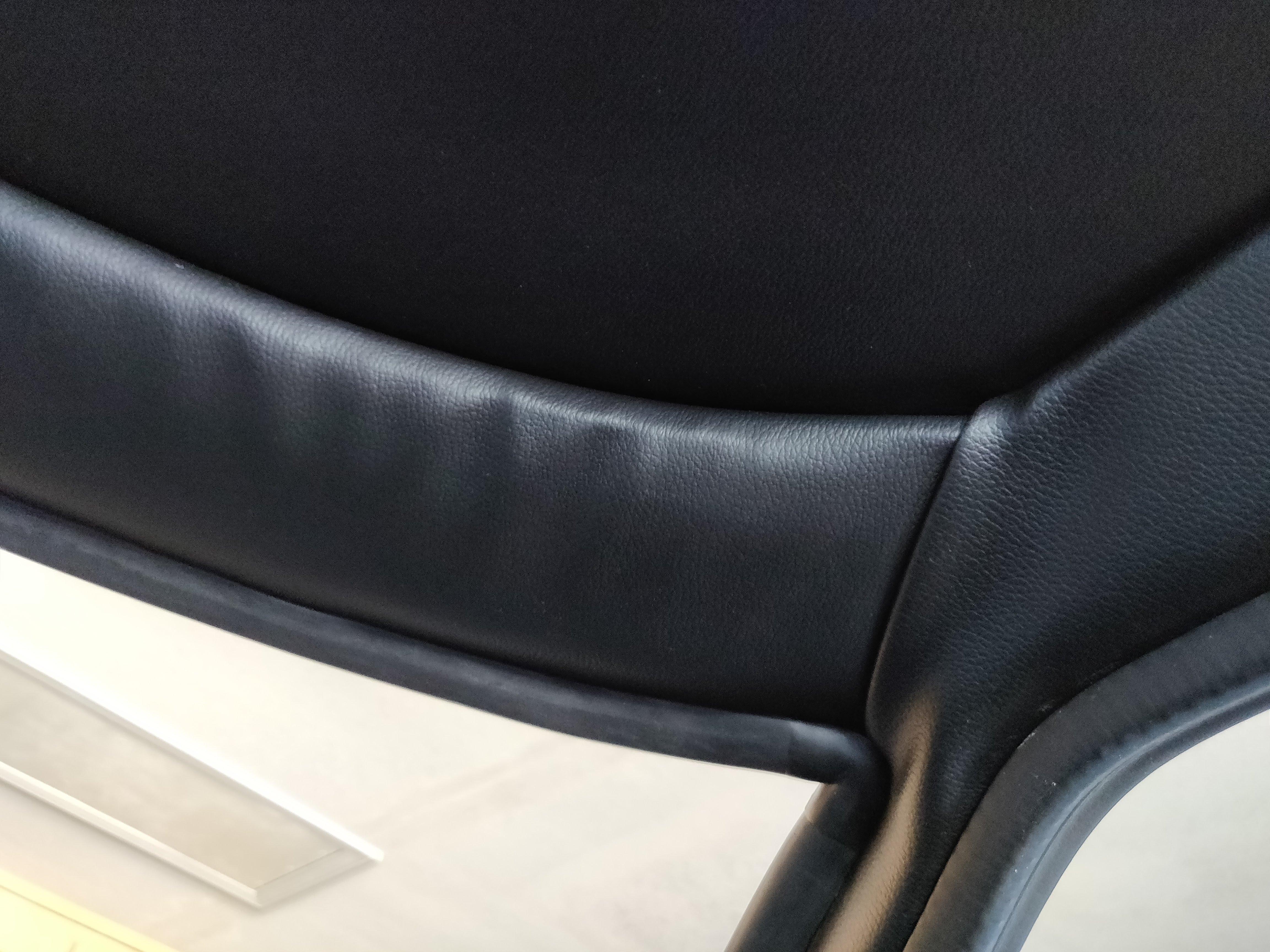
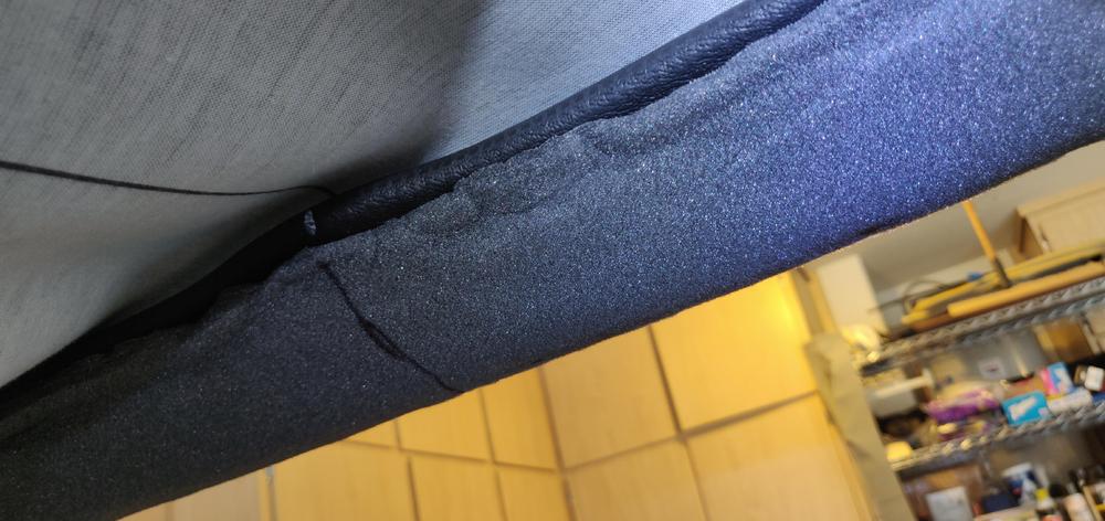
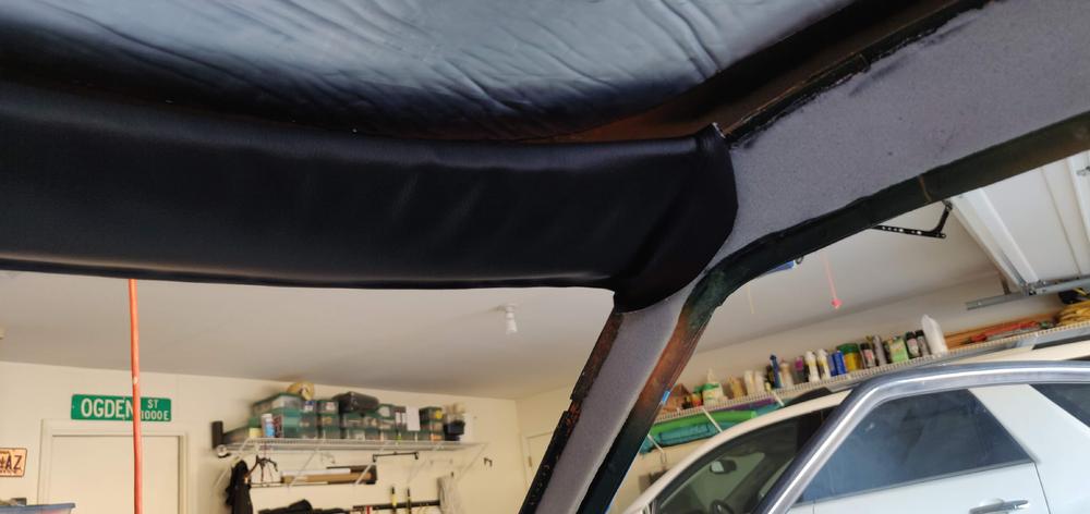
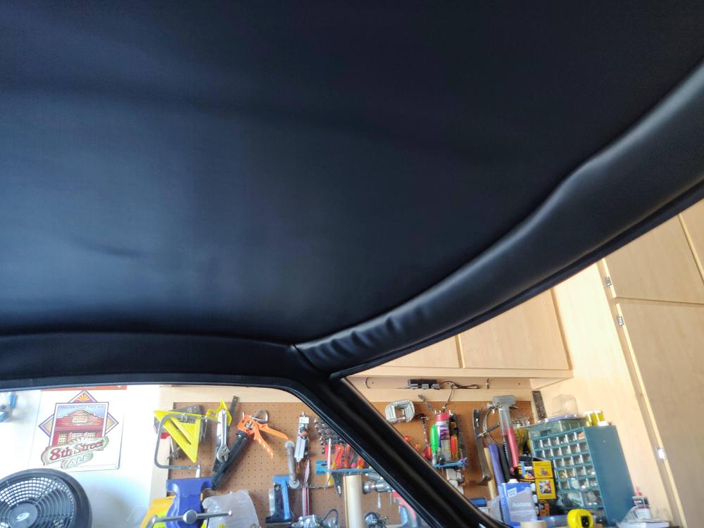
BTW, I bought the U-channel from McMaster-Carr - 10ft of part no. 24175K63 "U-Channel Push-on Trim Flame-Retardant, 3/16" Wide X 13/32" High Inside". Here are a few pictures of the process and the end result. It was much more of a PITA than it should have been. Windshield part of the roof rail with padding glued on and vinyl pinched into place with u-channel molding. . I trimmed the padding to be the full width of the rail, but only applied glue to the wide flat part so that the u-channel could fit under it (allowing the padding to overlap the u-channel). When gluing the vinyl in place, I started in the center and worked my way to the sides. I did not apply glue to the padding, hoping that it would make it easier (and more forgiving) to get the vinyl stretched properly into place. I still ended up with some wrinkles in the corners, where the sun visors attach. Here's the pinch molding attached to passenger side roof rail. And, then end result:


-
I just installed this kit not too long ago. It does have lots of extra material so you do need to trim it. The kit is also missing the pinch molding (also called steel reinforced rubber u-channel) you may need if yours is missing. It’s used to secure one edge of the trim pieces to the roof rail before wrapping them down and around and gluing the other edge. It’s possible to install without the pinch molding, but I thought it would give me a way to get the pieces lined up in an “undoable” way, and I’m glad I did. I glued the padding in place first and trimmed it, then pinched the windshield piece in place. Repeated with the side pieces, doing the roof rail part first, then the A-pillars. Sent from my iPad using Tapatalk Pro
-
Modified my Dave Irwin headlight relay harness by replacing the 240Z non-weatherproof connectors with Delphi WeatherPack connectors. I did not want to hack up my original 280Z headlight pigtails with their impossible-to-find Yazaki YPC connectors.