Matthew Abate
Free Member
-
Joined
-
Last visited
Everything posted by Matthew Abate
-
 Okay, the body harness has been stripped. I am very glad I didn’t try to use this thing. It’s melted / burnt in two places and has been messed with and rewrapped in three places. The next step is to compare this to the diagram and see what the story is.
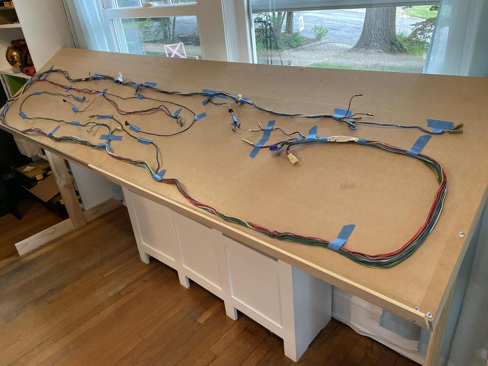
-
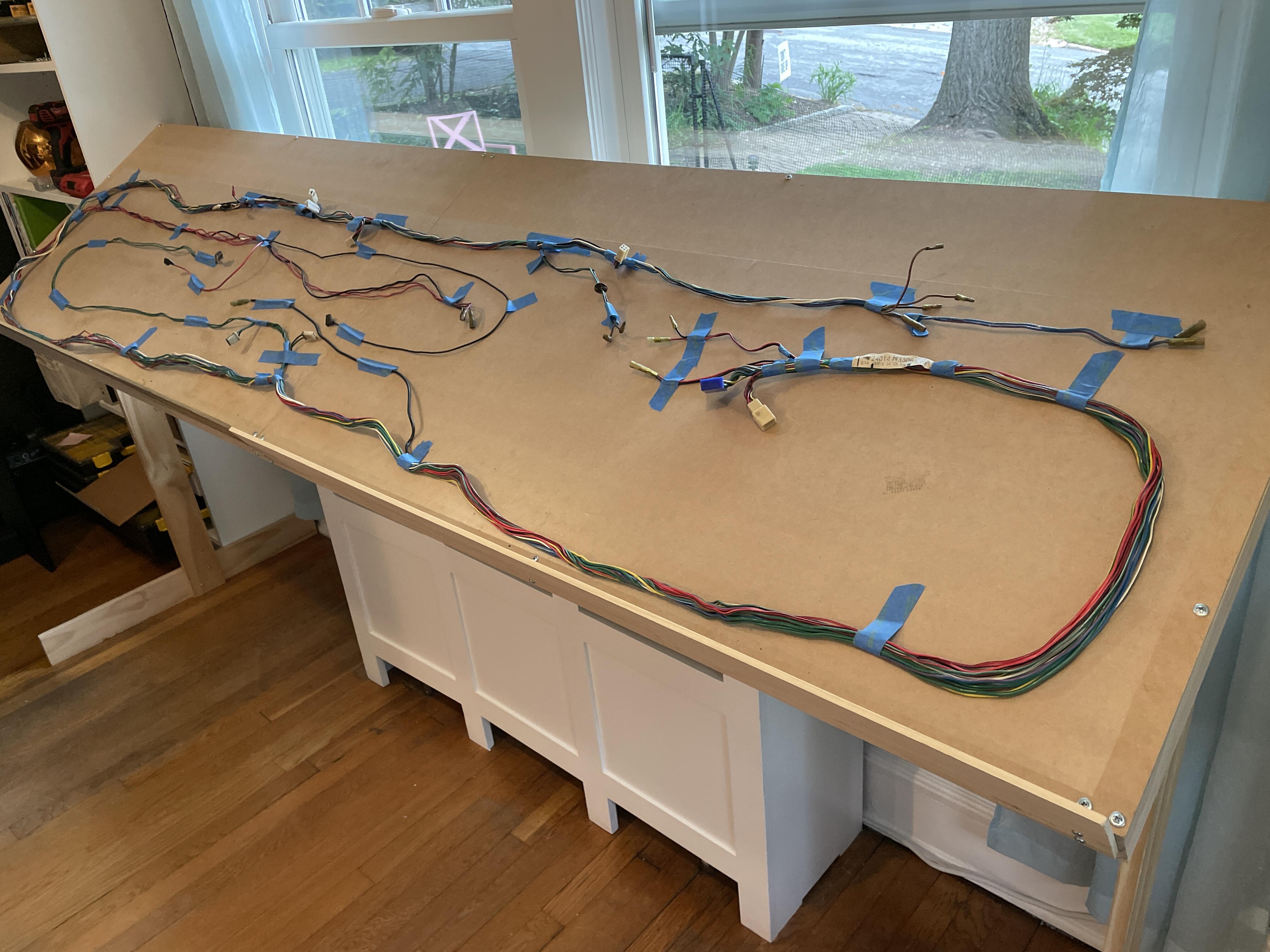
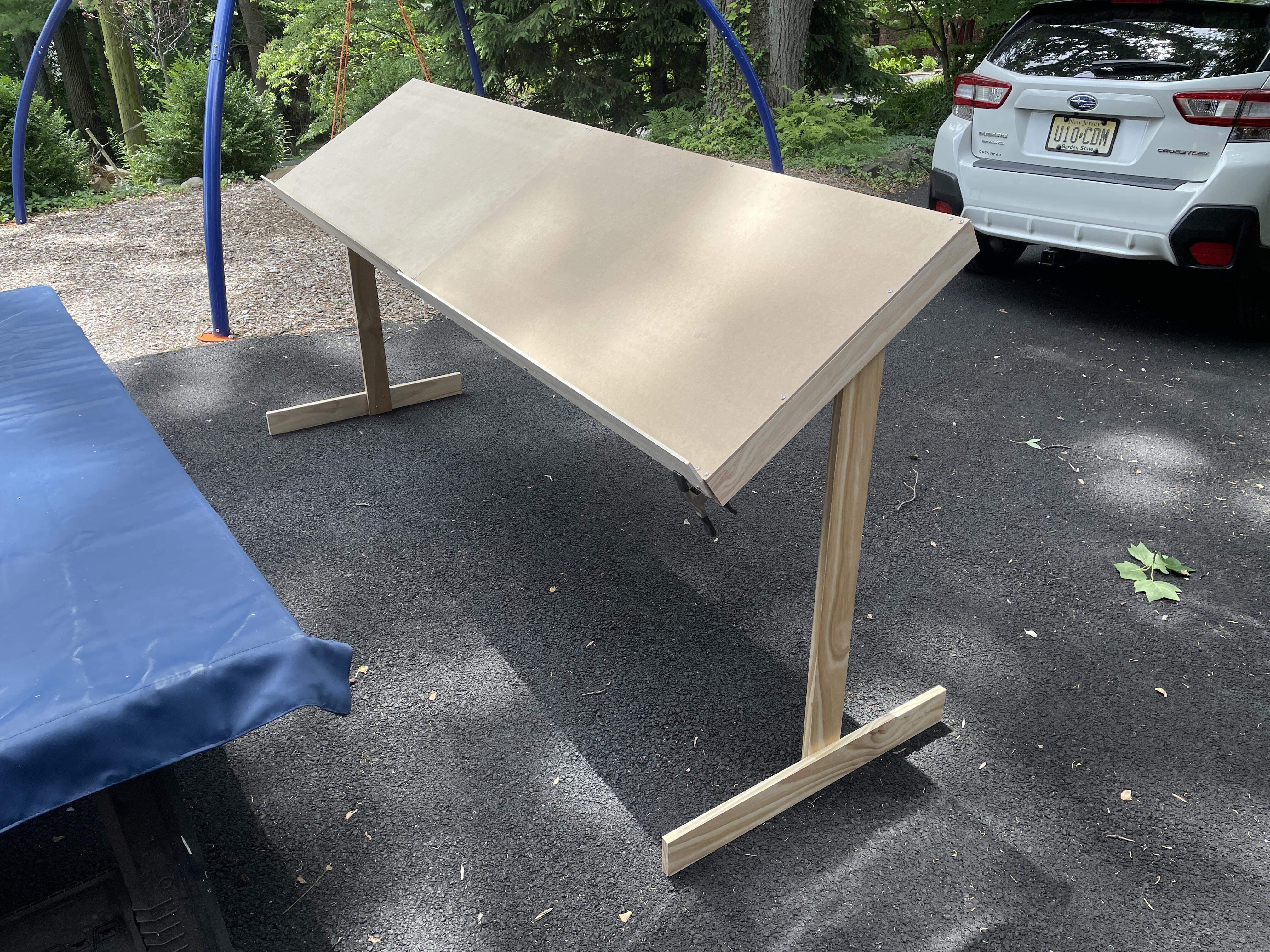
Okay. Made a nail board… It’s flimsy and probably too small, but it fits in my home office so I can theoretically work on this when it’s crazy hot out. I’m hoping that makes the project more likely to move forward.

-
This is super cool! It also sort of negates the reason I got a 240z, which is to have a car with no computer that I can fix myself. It also costs 2/3rds what the car cost me. I am looking at going with a more modern ignition system though…
-
I have some noob questions maybe some of you can help me out with: Is it better to build the wiring for mods into the main body harness or make a separate one that attaches to the main one, given I am starting from scratch? Can I somehow repurpose the Thermo Switch / Thermo Relay for an automatic transmission to control my electric radiator fan? Could I repurpose the wires for the automatic antenna and antenna switch for anything, like power for a Bluetooth speaker, for example? Could I repurpose the wires for the Inhibitor switch for an automatic transmission for anything? Could I repurpose the wires for the indicator lamp for an automatic transmission for anything?
-
Also, I found this helpful in understanding what we are dealing with here:
-
I went through the wiring diagram I have, which I downloaded from this site, and captured the wire colors running to each component in the stock system. I am planning to use this list to figure out what color wire to change to when I am unable to source wiring in the stock colors, but I thought I would post it here for anyone who wants it. Item OEM Wire Color Water tank • Black • Black w/ Yellow Side Marker Lamp RH • Black • Green w/ Blue Inspection Light • Ground • Red w/ Blue Horn Relay • Green • Green w/ Black • Green w/ Red Battery • Black • Black • Ground Accessory Relay • Blue • Black • White w/ Red • Blue Choke Switch • Black • Red w/ Blue Map Light • Black • Red w/ Blue Rheostat • Green w/ White • Red w/ Blue Fuel Pump • Yellow • Black Defrost Relay • Blue w/ Red • Black • White w/ Red • Red w/ Black Glove Box Light • Ground • Red w/ Blue Room Light • Black • Red w/ Blue Tank Unit • Yellow • Black Step Light RH • Black • Red w/ Blue Side Marker RH • Black • Green w/ White Ground • Black Rear Combination Light RH • White w/ Black • Green w/ White • Black • Red w/ Black Rear Combination Light RH Rear Combination Light RH License Light RH • Black • Black License Light LH • Black • Black Heat - Glass • Red w/ Black • Black Rear Combination Light LH • White w/ Black • Green w/ White • Black • Red w/ Black Rear Combination Light LH Rear Combination Light LH Auto Antenna • Blue w/ Red • Blue w/ White • Black • Antenna Lead Antenna switch • Blue w/ Red • Blue w/ White • Blue Side Marker LH • Black • Green w/ White Step Light LH • Black • Red w/ Blue Comb. Switch • Green w/ Blue (1) • Green w/ White (2) • White w/ Red (19) • Black (3) • Blue w/ Yellow (4) • Blue w/ White (5) • Red (20) • Blue (6) • Red w/ Blue (7) • Blue w/ Red (8) --- • Green w/ Yellow (9) • White w/ Red (10) • White w/ Black (11) • Green w/ Red (12) • Green w/ Black (13) • White (14) • Red w/ White (15) • Red w/ Black (16) • _____ (17) • Green w/ Black (18) Hand Break Switch • Ground • Yellow w/ Blue Speedometer • Red w/ Blue • Red w/ Blue • Red • Red w/ White • Yellow w/ Blue • Red w/ Blue Tachometer • Green • Red w/ Blue • Green w/ Black • Green w/ White • Black w/ White • Green w/ Red • Red w/ Blue • Black Oil Pressure / Water Temp • Black • Yellow w/ White • Green to Yellow w/ Red • Red w/ Blue • Green to Yellow w/ Red • Yellow w/ White Fuel Gauge / Ammeter • White w/ Red • White • Red w/ Blue • Yellow • Green to Yellow w/ Red • Black Clock • Black • Red w/ Blue • Blue Choke Warning Light • Red w/ Blue • Red Defrost Switch • [MISSING] • Blue w/ Red • Blue Seatbelt Warning Light • Black • Green Fog Light Switch • Red • Red w/ Green Door Switch RH • Black • Black • Ground Cigarette Lighter • Blue w/ White • Black Seat Switch • Red • Green w/ Black Seatbelt Switch LH • Green w/ Black • Green Seatbelt Switch RH • Green • Green w/ Black Neutral Switch • Green • Green Buzzer • Green • Black Door Switch LH • Black • Black • Black • Black • Ground Indicator Lamp (Auto T/M) • Black • Red w/ Blue Hazard Switch • Green w/ White (1) • Green w/ Red (2) • Green w/ Black (3) • Green (4) • Green (5) • Green w/ Yellow (6) • Green w/ Yellow (7) • White w/ Black (8) • White w/ Red (9) Ignition Switch • Black w/ Yellow (1) • Black w/ White (2) • White w/ Red (3) • Blue w/ Red (4) • Green w/ Blue (5) Steering Lock Switch • Red • Black Wiper Motor • Black (E) • Blue w/ Red (B) • Blue (L) • Blue w/ White (M) • Blue w/ Yellow (H) Buzzer • Yellow • Red Inhibitor Switch (Auto T/M) • Black w/ Yellow • Black w/ Yellow • Red w/ Black • Red Air Con Power • Red to Blue Blower Switch • Red • Black • Black Heater / Blower • Red • Black • Black • Ground Side Marker Lamp LH • Black • Green w/ Blue Parking & T/S & Side Front LH • Black • Green w/ Red • Green w/ Blue Head Light LH • Red w/ Black • Red w/ White • Red w/ Yellow Horn L • Green • Ground Fog Light LH • Black • Red Fog Light RH • Black • Red Horn R • Green • Ground Head Light RH • Red w/ Black • Red w/ White • Red w/ Yellow Parking & T/S & Side Front RH • Black • Green w/ Blue • Green w/ Black Voltage Regulator • Black (E) • White (A) • White w/ Black (F) • Yellow (N) • _____ (L) • _____ (–) • Black w/ White (IG) Thermal T/M • Yellow w/ White • Ground Oil Pressure • Yellow w/ White • Ground Fuse Box • Green w/ Red (H) • Green w/ Yellow (S) • Red w/ Blue (PT) • Red w/ Blue (PL) • Red (HR) • Red w/ Yellow (HL) • Blue w/ White (C) • Blue (A) • Blue w/ Red (W) • _____ (F) • Black w/ White (IG) • Blue w/ Red (C) • _____ (–) • _____ (–) • _____ (–) • Red (–) • White w/ Red (A) • White w/ Red (A) • _____ (–) • White (B) Starter Motor • Black • Black • Black w/ Yellow • Ground Fusable Link • Black Radio • Ground • Black • Red w/ Blue • Antenna Lead Reverse Switch • Red w/ Black • Red Turn Signal Flash Switch • Green • White Four Way Flasher • Blue w/ White • Green w/ White Brake Indicator • Yellow w/ Blue • Ground Stop Switch • Green w/ Yellow • Green w/ Yellow Ballast Resistor • Green w/ White • Black w/ White Thermo sw (Auto T/m) • Black w/ White • Green Alternator • Black (E) • _____ (A) • White w/ Black (F) • Yellow (N) • _____ (–) • _____ (–) • _____ (–) • _____ (–) • _____ (–) • _____ (–) • Fusible Link (A) • Black (E) Fusable Link • White w/ Red Thermo Relay (Auto T/M0 • Green • Black • Black • Red w/ Black to Black Coil • Black • (To Distributor) Distributor (Manual T/M) • Black • (From Coil)
-
Thanks @zKars! I'll take your comments into account. I was already leaning toward Deutsch or Weatherpack connectors. The gauges I had not considered changing due to the lack of dual options out there, but I'll look around. In addition to suggestions for adding or swapping things, if anyone sees anything on my list that they think I should take off, please let me know. For example, I had someone tell me to ditch the electric fan and keep the original, but I am not sure about that because I am going to add air conditioning.
-
Thanks @SteveJ! I think you already noticed this based on your comments, but I'll state it for anyone else who may comment: My overall goal in this is to make the ideal wiring system for the car with consideration to the modifications I am going to make, not to replicate the original. That said, I don't want to deviate wildly from original because I want to be able to go back and fix stuff if necessary. I also want to reduce complexity and weight wherever possible. However, I also think I will go heavier than necessary with the wiring so I never have to worry about that part of the system. The things on the ends of the wires are a lot easier to fix down the road than the wires themselves. ___ Here is my first pass at an inventory of components for this project, sorted according to their position in the wiring diagram: Mod Item Replacement In Diagram? Stock Antenna Lead Delete Yes Stock Antenna Lead Delete Yes Stock Water tank Yes Upgrade Side Marker Lamp RH LED Bulb - Front Turn Signal Yes Upgrade Inspection Light LED Bulb - Inspection Light Yes Stock Horn Relay Yes Stock Battery Yes Stock Accessory Relay Yes Stock Choke Switch Yes Upgrade Map Light LED Bulb - Map Light Yes Stock Rheostat Yes Stock Fuel Pump Yes Stock Defrost Relay Yes Upgrade Glove Box Light LED Bulb - Glove Box Light Yes Upgrade Room Light LED Bulb - Dome Light Yes Upgrade Room Light Yes Stock Tank Unit Yes Stock Step Light RH Yes Upgrade Side Marker RH LED Bulb - Red Marker Light Yes Upgrade Rear Combination Light RH LED Bulb - Brake Light Yes Upgrade Rear Combination Light RH LED Bulb - Rear Turn Signal Yes Upgrade Rear Combination Light RH LED Bulb - Reverse Light Yes Upgrade License Light RH LED Bulb - Plate Light Yes Upgrade License Light LH LED Bulb - Plate Light Yes Stock Heat - Glass Yes Upgrade Rear Combination Light LH LED Bulb - Brake Light Yes Upgrade Rear Combination Light LH LED Bulb - Rear Turn Signal Yes Upgrade Rear Combination Light LH LED Bulb - Reverse Light Yes Stock Auto Antenna Delete Yes Stock Antenna switch Repurpose ??? Yes Stock Side Marker LH Yes Stock Step Light LH Yes Stock Comb. Switch Yes Stock Hand Break Switch Yes Stock Speedometer Yes Stock Tachometer Yes Stock Oil Pressure / Water Temp Yes Stock Fuel Gauge / Ammeter Voltmeter Yes Stock Clock Yes Stock Choke Warning Light Yes Stock Defrost Switch Yes Stock Seatbelt Warning Light Yes Stock Fog Light Switch Yes Stock Door Switch RH Yes Upgrade Cigarette Lighter 12 volt plug Yes Stock Seat Switch Yes Stock Seatbelt Switch LH Yes Stock Seatbelt Switch RH Yes Stock Neutral Switch Yes Stock Buzzer Yes Stock Door Switch LH Yes Stock Indicator Lamp (Auto T/M) Yes Stock Hazard Switch Yes Stock Ignition Switch Yes Stock Steering Lock Switch Yes Stock Wiper Motor 91 Honda Civic Wiper Motor Yes Addition Wiper Motor Wiper Upgrade Relay No Stock Buzzer Yes Stock Inhibitor Switch (Auto T/M) Yes Stock Air Con Power Yes Addition Air Conditioner No Stock Blower Switch Yes Stock Heater / Blower Yes Upgrade Side Marker Lamp LH LED Bulb - Front Turn Signal Yes Addition Side Marker Lamp LH Side Marker LED Conversion Plugs No Stock Parking & T/S & Side Front LH Yes Upgrade Head Light LH Headlight Projection Housings Yes Upgrade Head Light LH Headlight Projection Housings Yes Stock Horn L Yes Stock Fog Light LH Yes Stock Fog Light RH Yes Addition Front Fog / Rally Light Relay No Stock Horn R Yes Upgrade Head Light RH Headlight Projection Housings Yes Upgrade Head Light RH Headlight Projection Housings Yes Addition Head Light RH Headlight Relay Upgrade Harness No Upgrade Parking & T/S & Side Front RH LED Bulb - Front Turn Signal Yes Addition Parking & T/S & Side Front RH Parking Light Upgrade Harness No Addition Parking & T/S & Side Front RH Parking Light Upgrade Harness, 70-73 No Stock Volt Reg Yes Stock Voltage Regulator Yes Stock Thermal T/M Yes Stock Oil Pressure Yes Upgrade Fuse Box 280ZX Fuse Box Yes Upgrade Fuse Box Long Pigtail Blade Style Fuse Box Yes Upgrade Fuse Box Short Pigtail-Blade Style Fuse Box Yes Upgrade Fuse Box Short Pigtail-Blade Style Fuse Box Yes Upgrade Starter Motor Gear Reduced Starter Motor Yes Stock Fusable Link Circuit Breaker / Fuse Yes Upgrade Radio Stereo Delete Box Yes Stock Reverse Switch Yes Stock T/S Flash SW Yes Stock Four Way Flasher Yes Stock Brake Ind. Yes Stock Ballast Resistor Delete ??? Yes Stock Stop Sw Yes Stock Thermo sw (Auto T/m) Yes Upgrade Alternator Alternator - 100 Amp Yes Addition Alternator Alternator Upgrade Plug No Stock Fusable Link Circuit Breaker / Fuse Yes Stock Thermo Relay (Auto T/M0 Yes Stock Coil Yes Stock Distributor (Manual T/M) Yes Stock Distributor Condenser No Addition Anti-Theft Kit / Alarm N/A Addition Auxiliary Fuse Box N/A Addition Bluetooth Speaker Power N/A Addition Electric Radiator Fan N/A Addition Electric Radiator Fan Pigtail N/A Addition Electric Radiator Fan Temp Control Kit N/A Addition GPS Power N/A Addition Third Brake Light N/A Addition Under Dash / Footwell Lights N/A Addition USB Socket / Phone Charger N/A Upgrade LED Bulb - Dashboard Light Set N/A Stock Fuel Sender Electrical Connector No Stock Electric Fuel Pump Wiring Install Kit Harness Relay No @SteveJ, I don't know if I will be going with the ammeter I have or converting to a voltmeter. I need to look at the pros and cons of that change. In fact, I have not decided if I am keeping the factory gauges at all. This is a restomod and I have already made irreversible changes, so I don't know. I might also address the 9-pin switch by backdating that to an earlier version. Any suggestions on other changes anyone has that will make the car better would be much appreciated. I am hoping this thread can turn into a resource for others and not just me tracking my progress.
-
Okay, I've decided to start a new build thread dedicated to this wiring project. I think it is going to be complicated enough to necessitate its own space. Here's the link:
-
I have decided that the wiring on my '73 is going to be complicated enough to warrant it's own build thread. I will post the high level stuff in the full-car build thread (https://www.classiczcars.com/forums/topic/51541-1973-rebuild/#comments), but the details and back and forth conversation will be here. This is going to be a huge learning process for me since I have no experience in this area. With that said, this is where I am with this so far… When I got the car, the harnesses were installed, but the car was otherwise stripped. I pulled the harnesses, gave them a cursory dusting off and stuffed them into a box. The dash harness is still on the dashboard, which is on a shelf. I have been tracking an inventory of modifications I want to make to my electrical system over the past few years as I work on the rest of the car. I had a lot of ambition when I first put this list together, but I have backed off from my initial list of additional components over time. This is what I am still thinking about doing: Anti-Theft Kit / Alarm (Mostly because I have one laying around that I never installed on my motorcycle) Auxiliary Fuse Box or an Upgraded Fuse Box Bluetooth Speaker Electric Radiator Fan, plus maybe a thermostat controlled switch that would allow it to run after to car is turned off. GPS Third Brake Light Under Dash / Footwell Lights USB Socket / Phone Charger LED Exterior Lights 100-Amp Alternator Radio Delete LED Headlights Rally / Fog Lights 12-volt Socket (Replaces Cigarette Lighter) Door / Step Lights (These are super rare and way too expensive) Other Considerations… Figure out where I am going to do this work (it's getting hot) Decide which type of wire for each component (TXL, SXL, GXL, etc.) Choose connectors (Original style?, Deutsch style?, AMP style?, Weatherpack style?) Decide which colors to use for each color in the original harnesses Find amperage / voltage / wattage for each component Determine ideal wire size for each component Choose distributor Choose fuse box, distribution block, relay upgrades Identify fuse and relay requirements for each component Draw up new / modified wiring diagram Choose wrapping material Find shrink-wrap labels for label maker Find retailers ___ Right now I have a pretty solid spreadsheet put together with all of the components I need, mapped to the wiring diagram, and tracking the parts I plan to buy. Oh, and I’ve never done automotive wiring before, so this will be an experience.
-
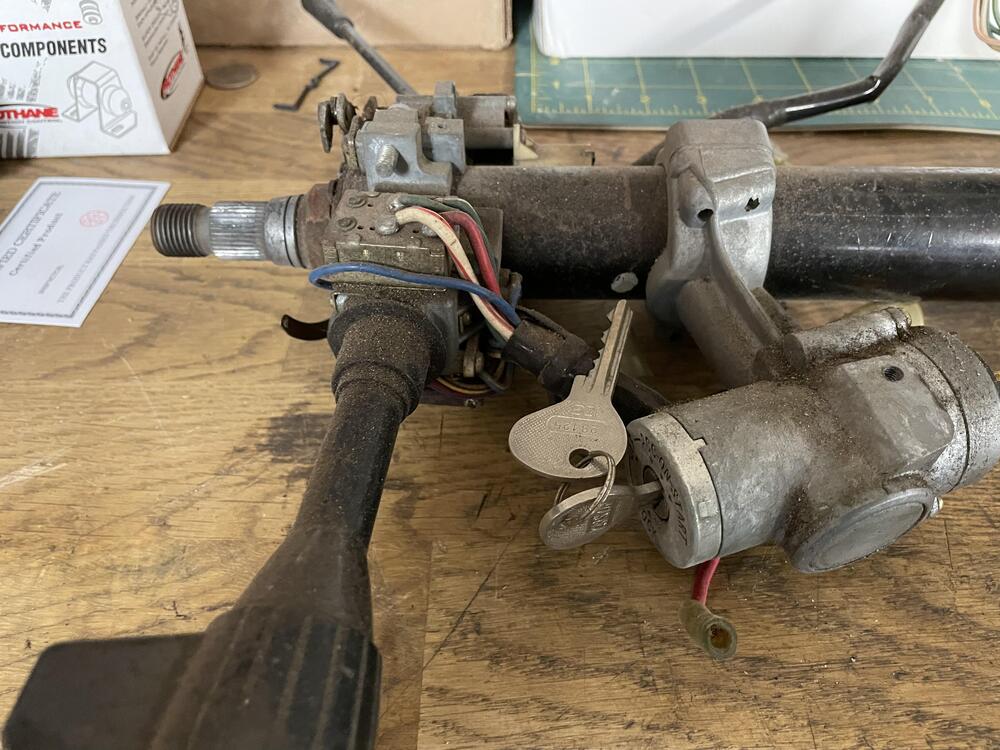
Getting ready to work on installing the firewall insulation and other parts. Can anyone point me to a good thread about the sequence here? I’ve seen several threads about the overall sequence of the interior, but they all sort of gloss over this part. The specific information I’m looking for is the order for these items: Sound deadener / Dynamat Grommets Heat shield/jute or similar Black card pieces / kick panels Wiring Pedal Box Steering Column Heater Blower Dashboard I assume that’s the right order, but if anyone thinks differently let me know. What are the pitfalls I’m overlooking?
-
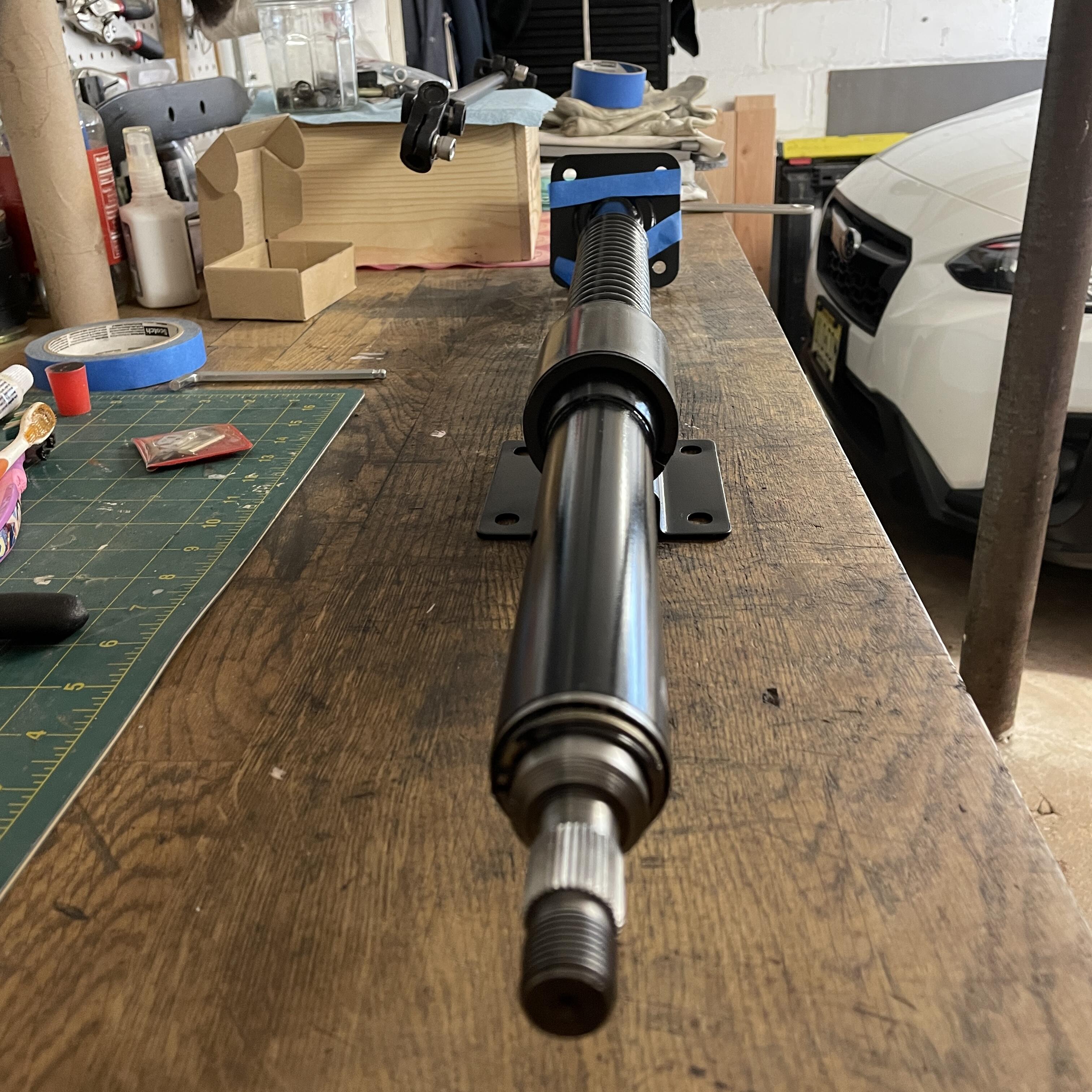
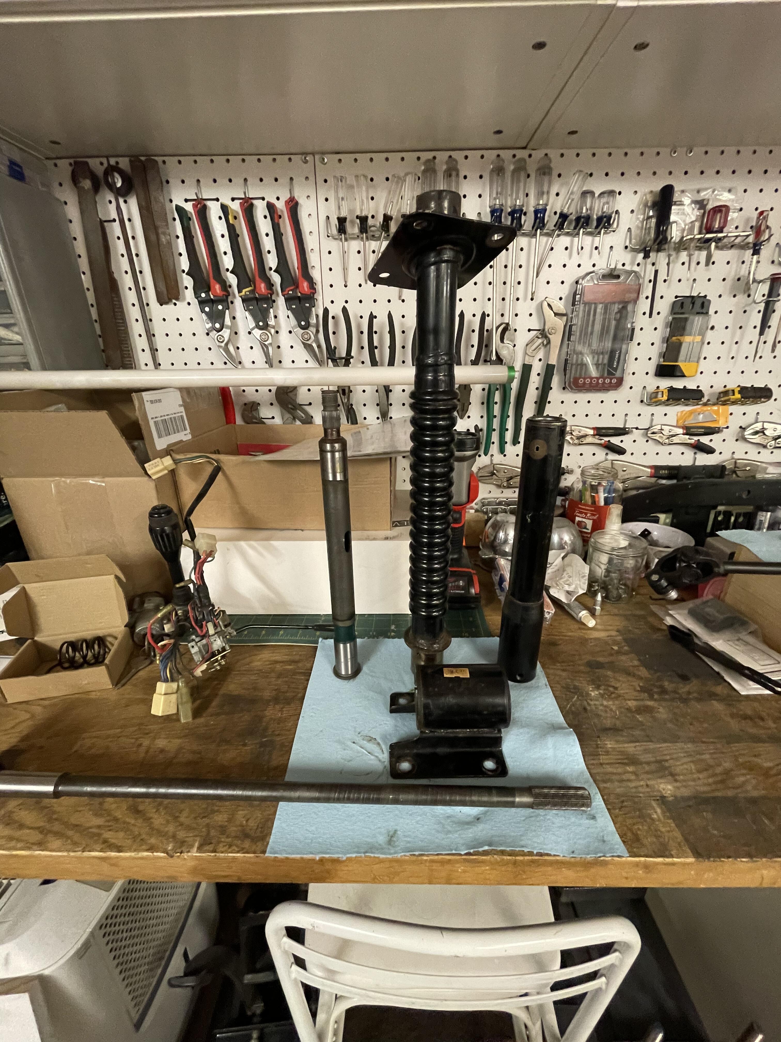
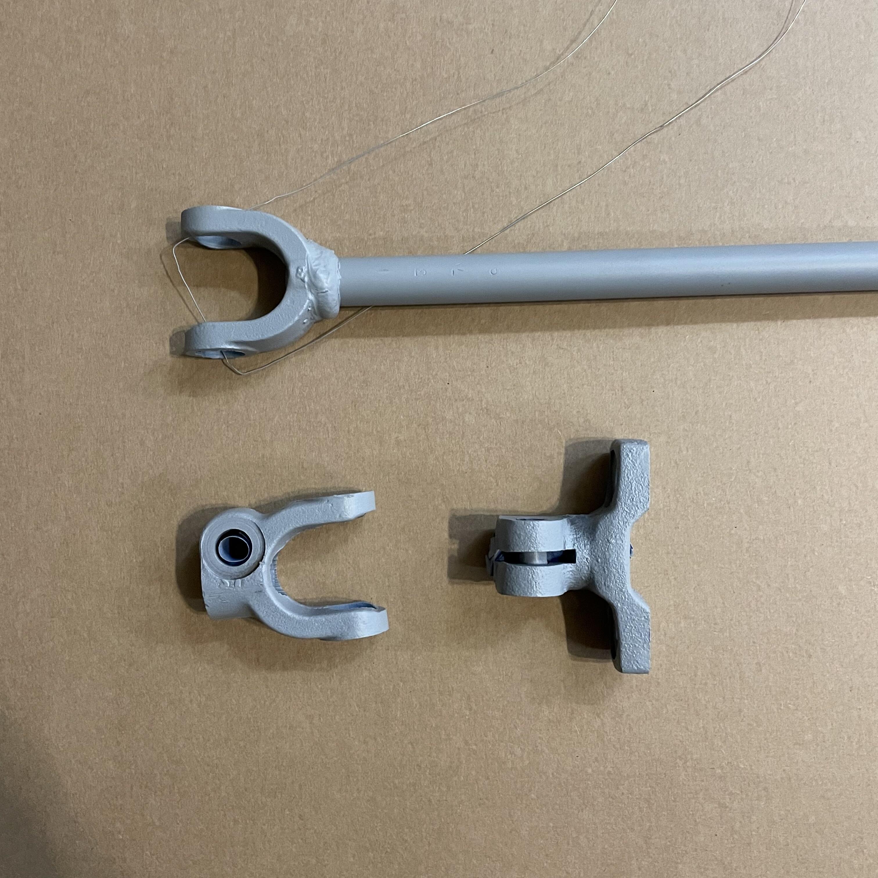
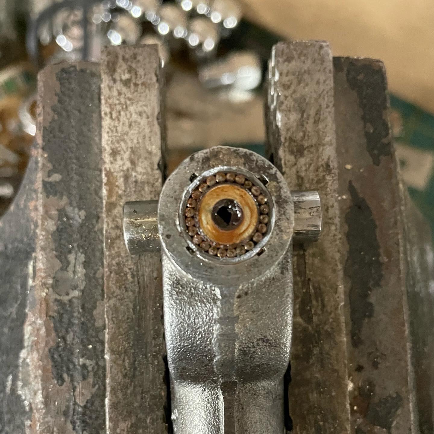
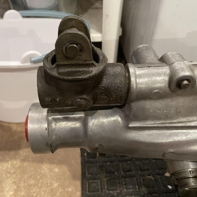
Back together: I found this component to be a pretty simple refresh project… if you don’t try to pull the bearings or the plastic bushing out of the column as I’ve seen done in other threads. I used a variety of degreasing sprays, patience, time, and gravity to clear everything out. I think eight rounds and it was flushing out clean. Then repacked the bearings using more patience and a syringe full of grease. It took way too long but it worked. Primer and paint were harder given the poor weather in the north east over the last several weeks. It took a full week for each coat to completely cure. And that’s in the heated garage with a dehumidifier running 24/7. Hence the drawn out timing of this process.


-
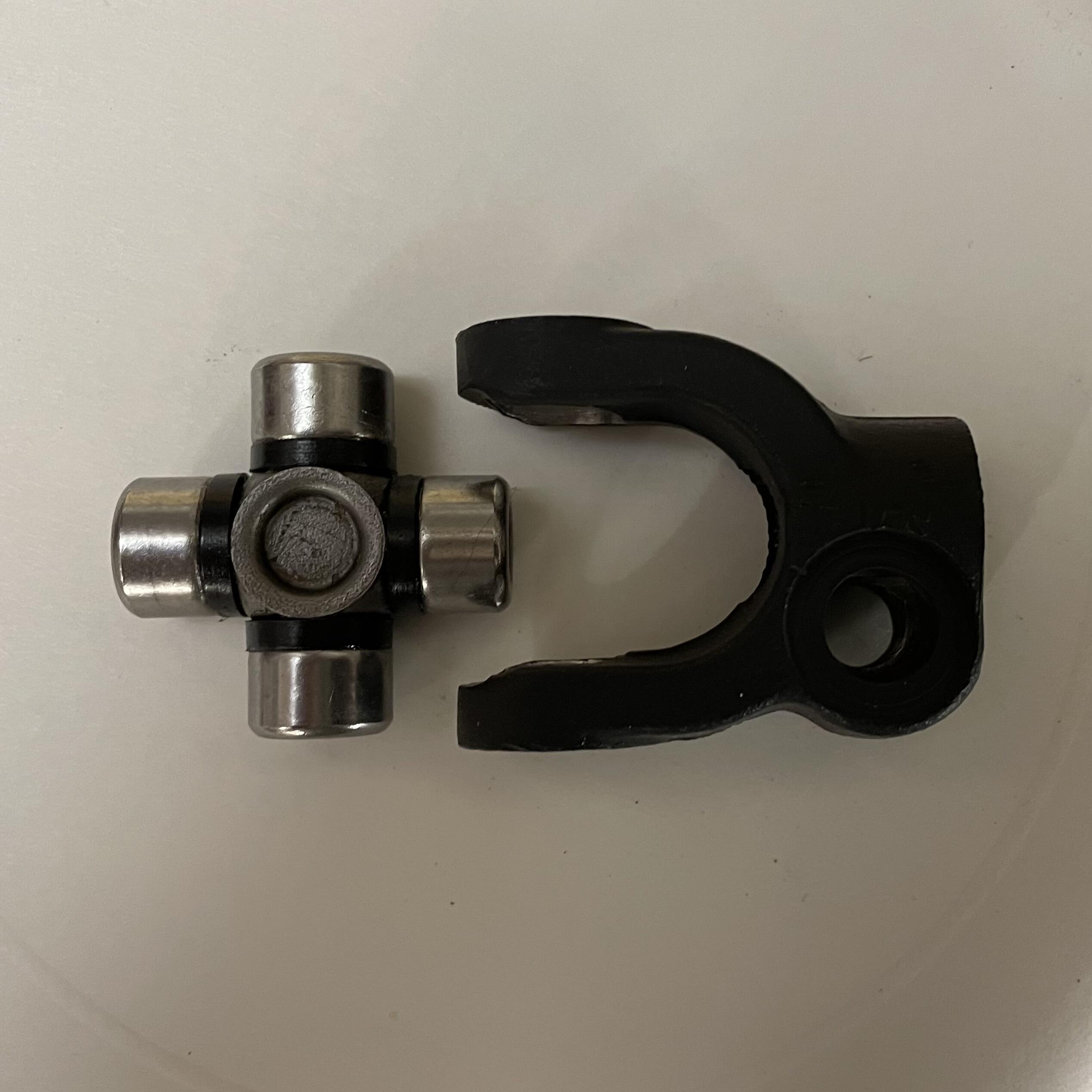
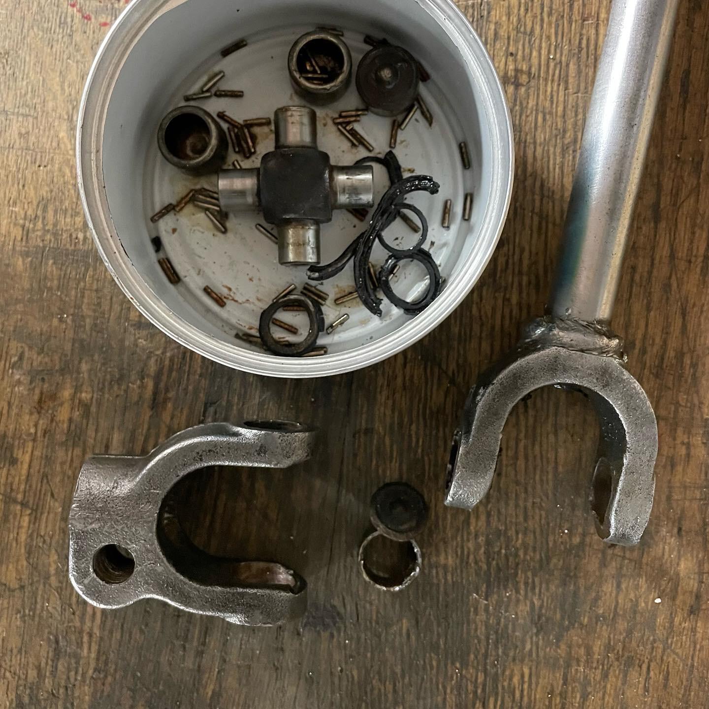
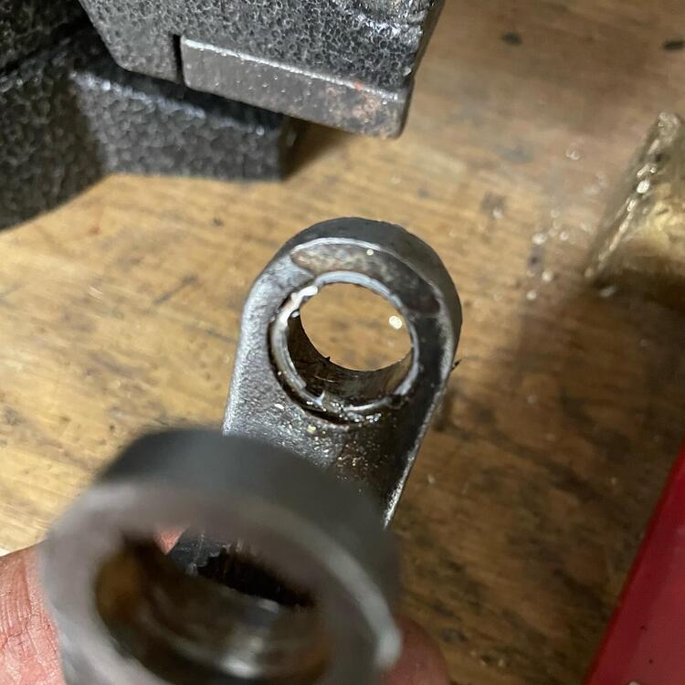
So this is the next thing I’m working on. Cross your fingers that other u-joint survives the cleaning process and I don’t spiral into another repair process. 🙄


-
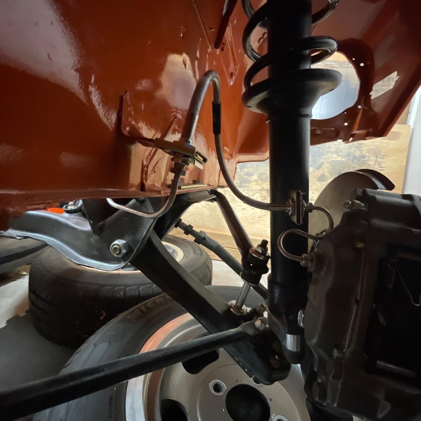
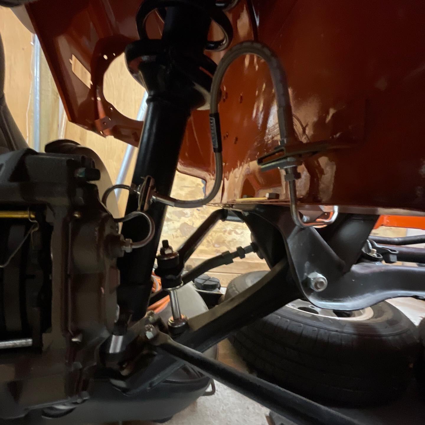
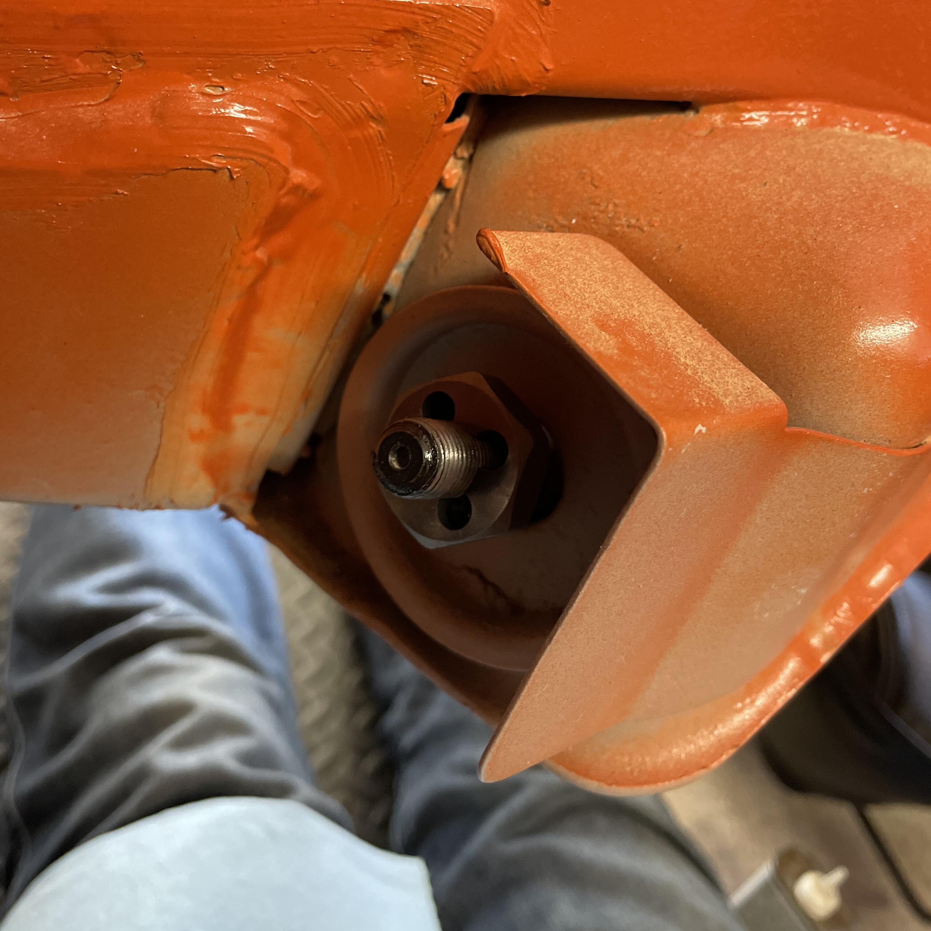
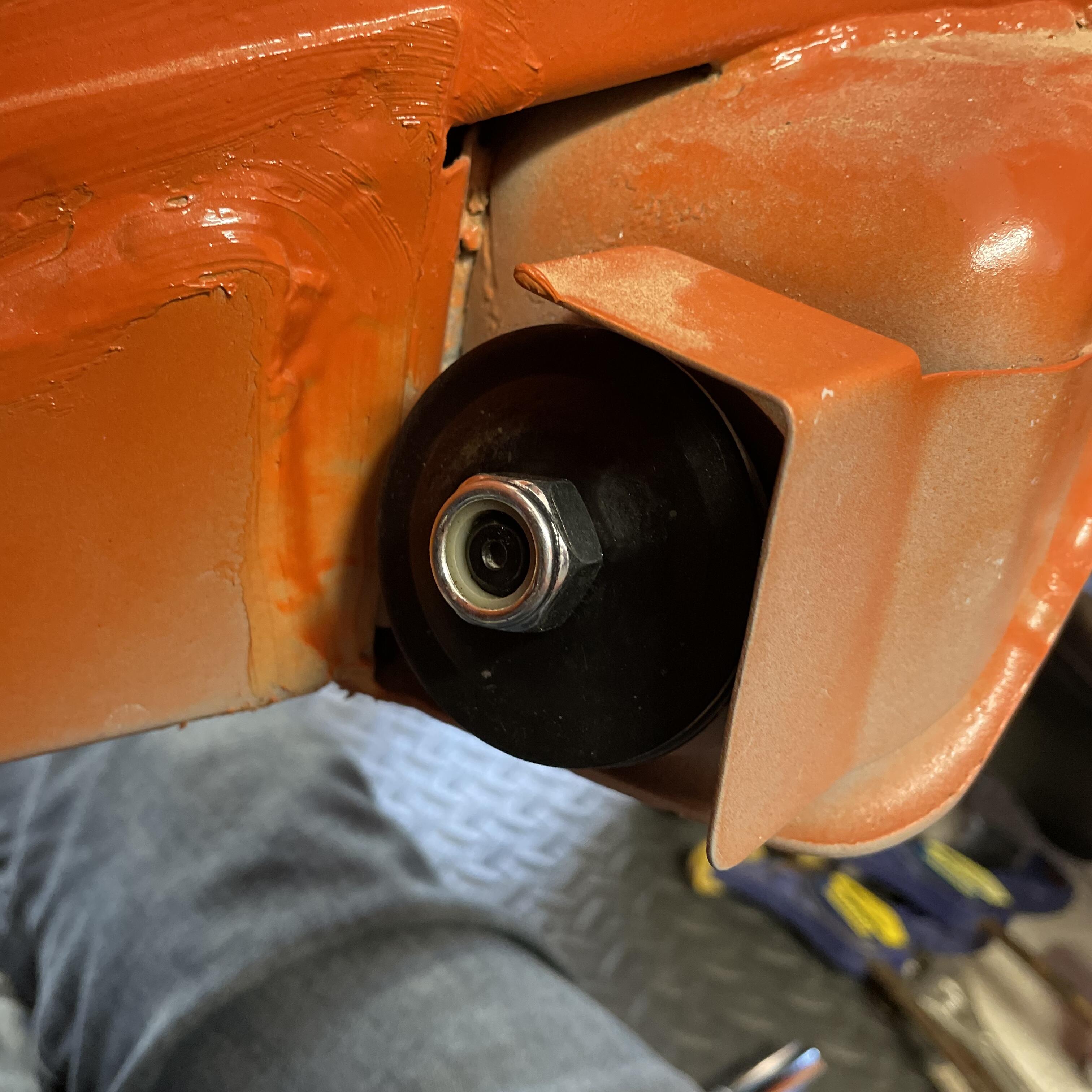
Getting this tension rods tighter meant I could move back to the brakes. I now have a complete system between the distribution block and all four calipers. Now I will check my torque on all of the fittings. Then I can go back to rebuilding my master cylinder and start thinking about rehabilitating my pedal box.


-
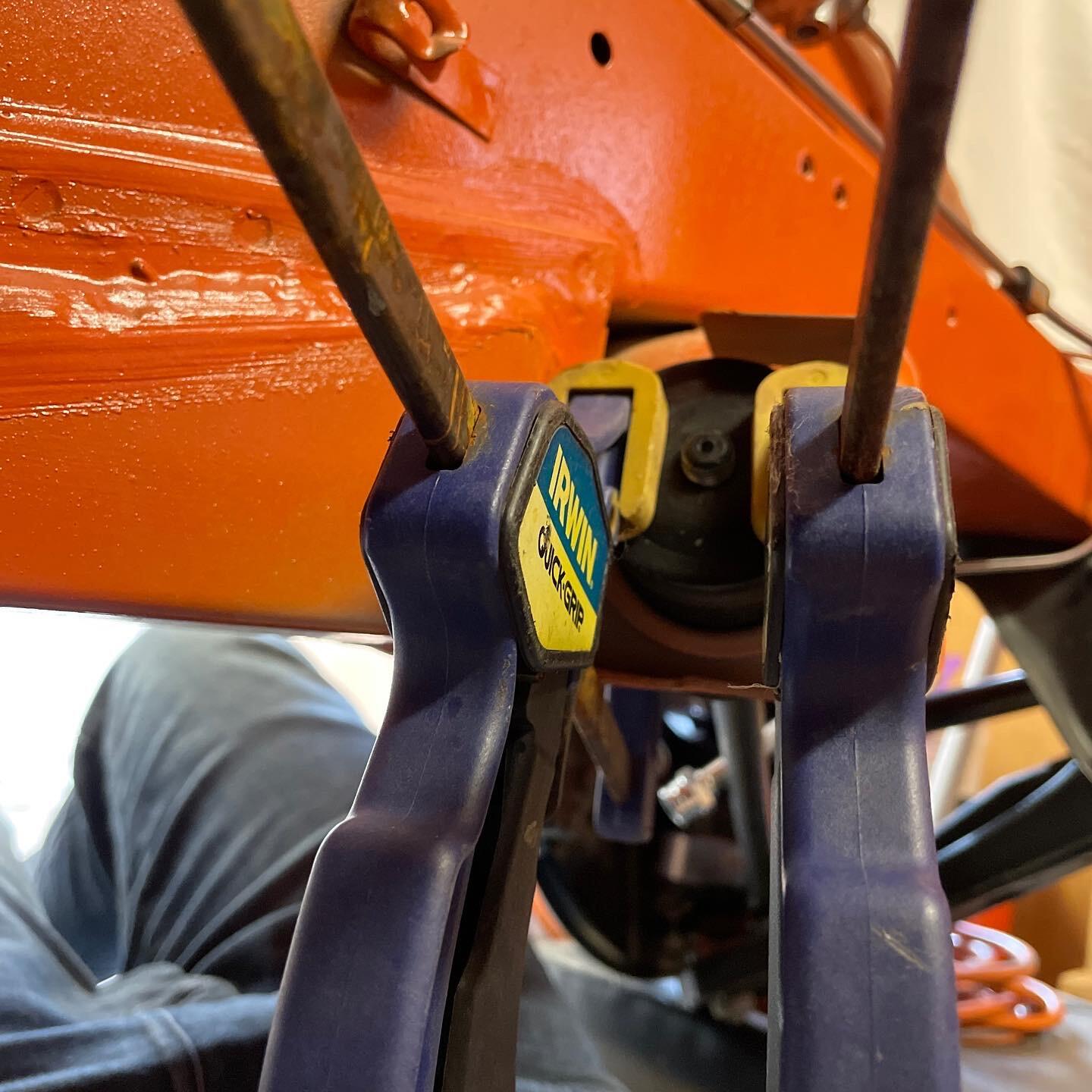
I was making it WAY WAY WAY more complicated than it needed to be. The bushings are rubber so they’re pretty soft. Cleaning up the threads and two carpenter’s clamps did the trick. I’m going to wait until the engine is in to torque them. Right now they are just on to the nylon so I don’t have to worry about the single-use factor.


-
I have the car in four jack stands and it’s nearly empty (no engine, no interior). I tried spring compressors but they don’t fit in the space around the spring. I also tried using four ratcheting tie down straps but it started to feel dangerous so I abandoned that route.
-
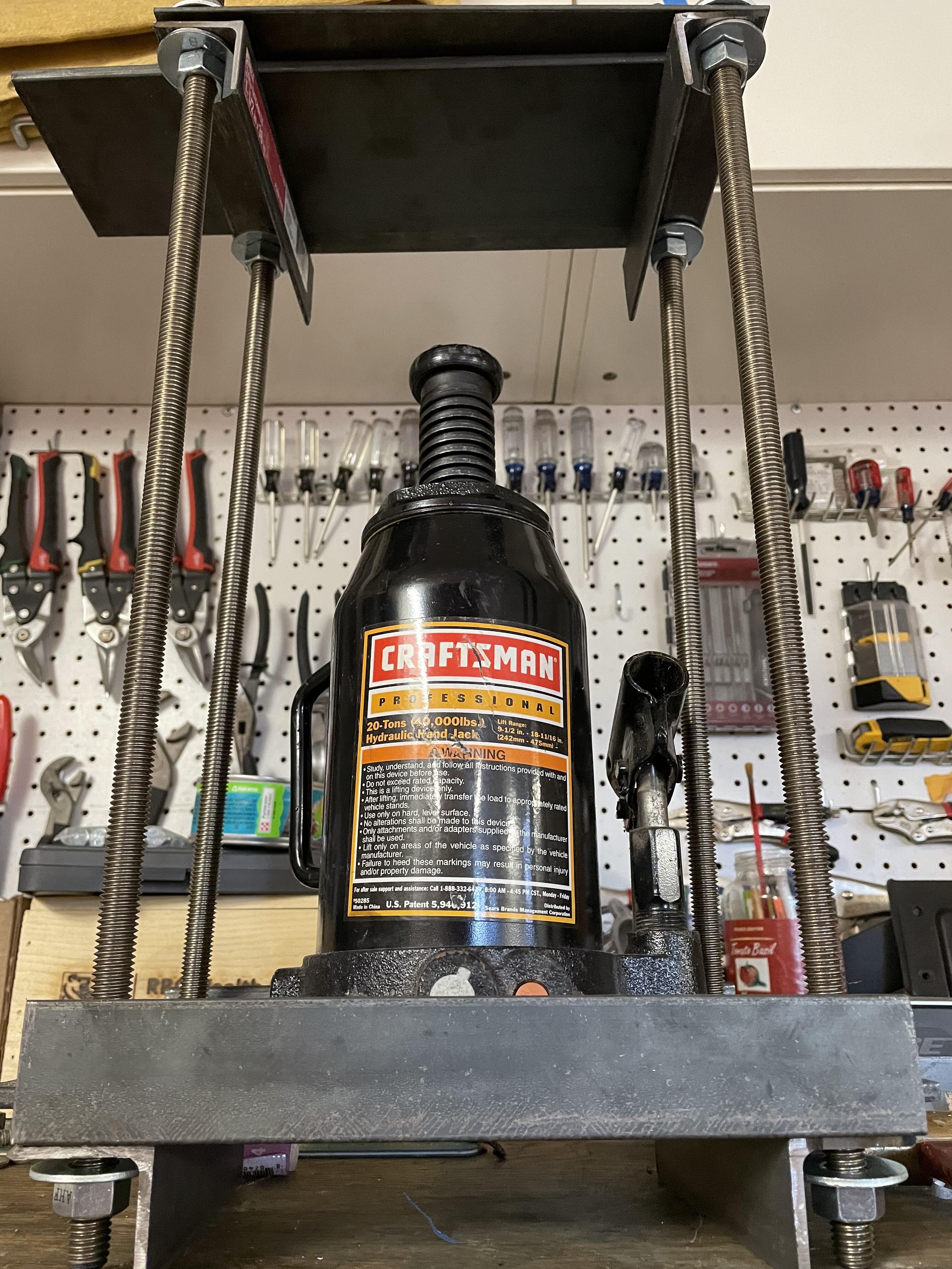
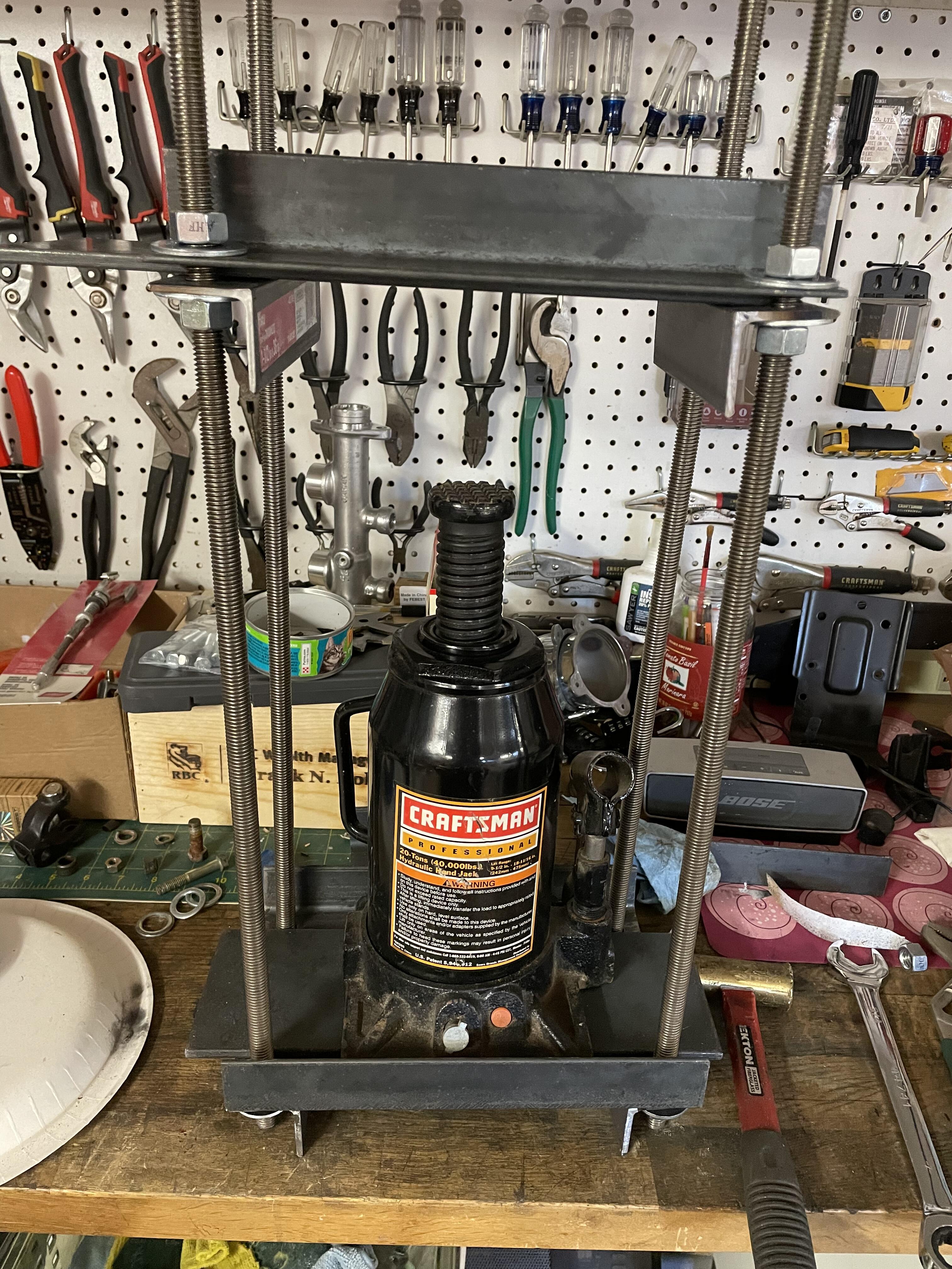
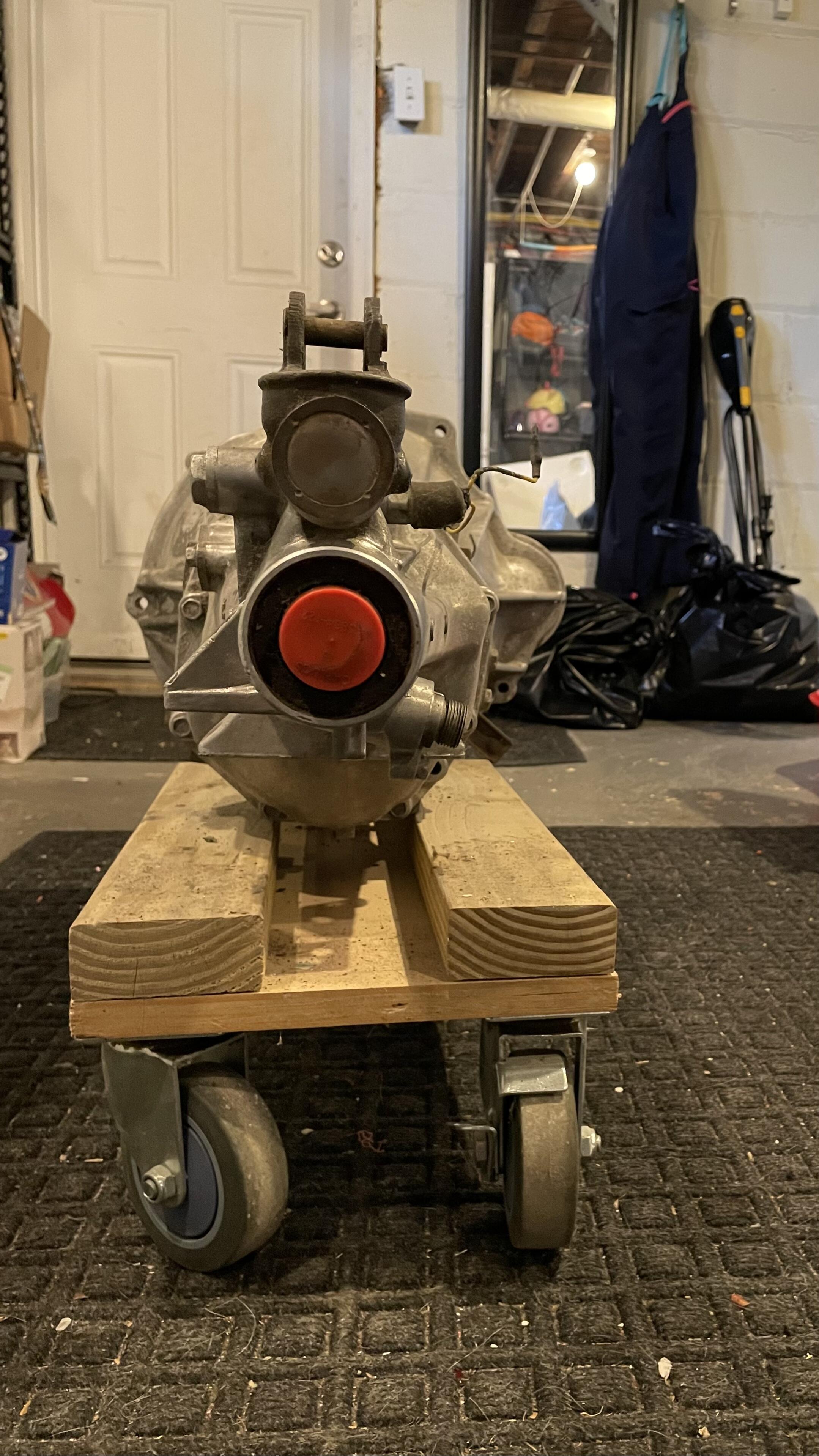
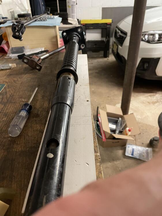
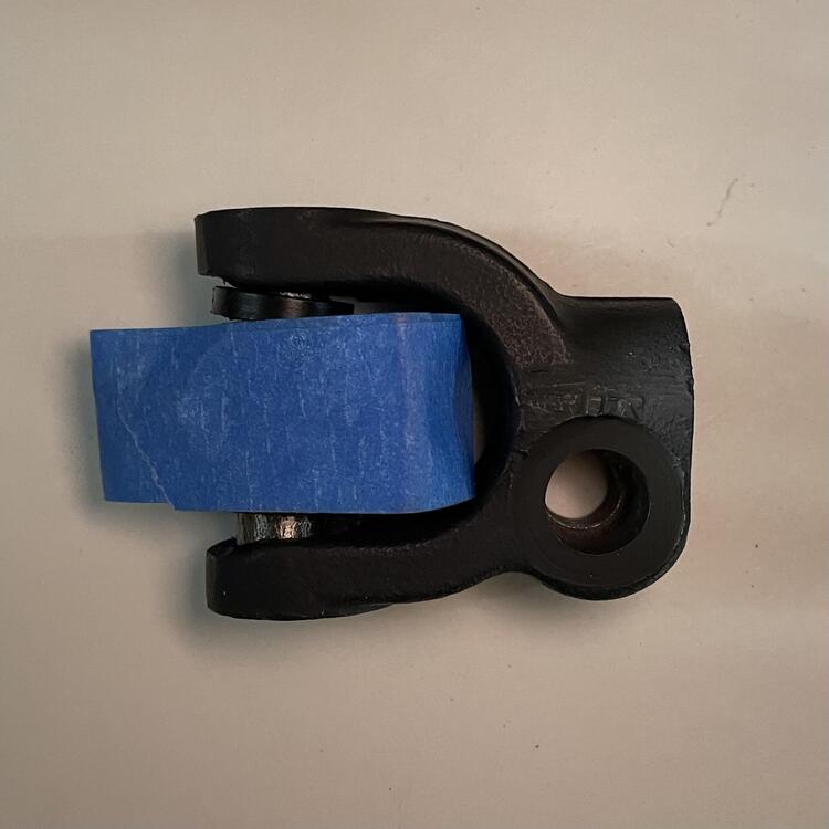
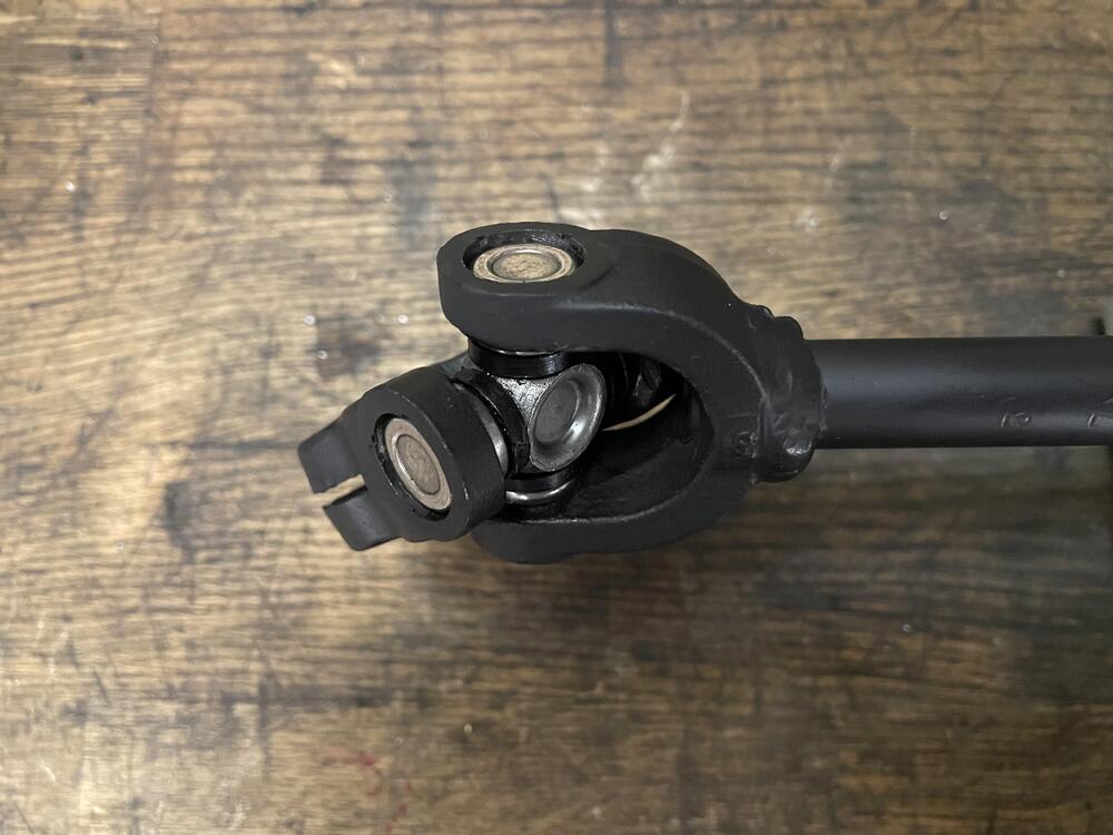
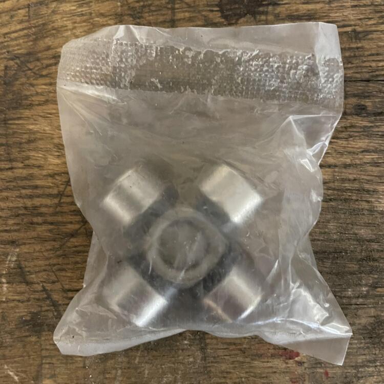
Had several setbacks this month… Setback #1. The u-joint was a major PITA to get in and I ruined the first one putting it in, so I had to wait an additional two weeks for a replacement. While I waited I built myself a hydraulic press. It’s really just a box my bottle jack fits in, but it does the job. With that I was able to get the steering shaft back together the right way. The u-joint isn’t as nice in real life as the photo on Amazon indicated. Go figure. Restaking that thing was super tough, but I got it done and nothing is moving. —- Setback #2. I cannot seem to get the nuts on the tie rods that connect the lower control arms to the frame in the front of the car. Because the suspension is sagging they don’t protrude far enough, and the rubber bushings are brand new so they don’t give enough to cram it on. This is a problem because I need my suspension to compress a bit to keep the brake lines from getting pulled taught and sitting there under tension while I do other stuff (yes they are the right length). Tightening this up will create the slack I want. Since the engine is out I have to figure out another way to get some weight on the front to settle things in place and get that tightened up. Sandbags maybe? —- Setback #3 (This really pissed me off). It turns out the differential I bought that supposedly came out of a 2014 Subaru WRX STI is NOT out of an STI. If it was it would be the LSD I wanted. Instead it is open, which means it is from a WRX, Outback, or Forester. Unfortunately I’ve had it too long to complain or get any compensation. So all that time and money I spent rebuilding it is semi-wasted. The reason I noticed is I realized that I didn’t want a 3.9 rear end, which the STI also has. When I put the adapters in and checked the ratios this evening I noticed the sides rotated opposite directions. NOT AN LSD!!! So what I have is an immaculate r180 with an open differential and a 3.54 ratio. Not ideal, but slightly quicker than stock. It’s essentially the same as the dif for an automatic. Now I have to decide how much I care about having an LSD. Do I go buy the correct carrier from Subaru for $750? That’s a Torsten style and would be nice. Do I get a fancy aftermarket dif for over a grand? Those are helical and probably overkill. Or do I live with this thing on my bench. Easiest and cheapest but I’m the kind of person who is forever bothered by things not being “right.” Putting my Datsun dif back in is also an option, but it would need a rebuild. Anyway, on with the show.


-
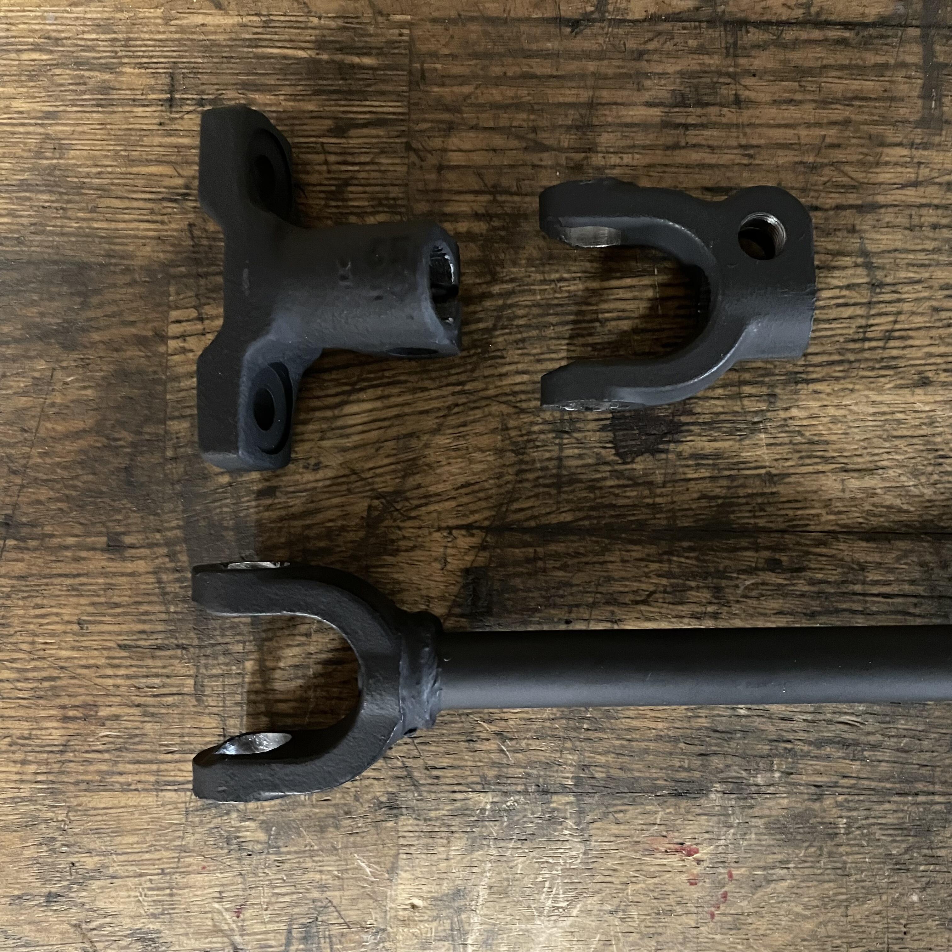
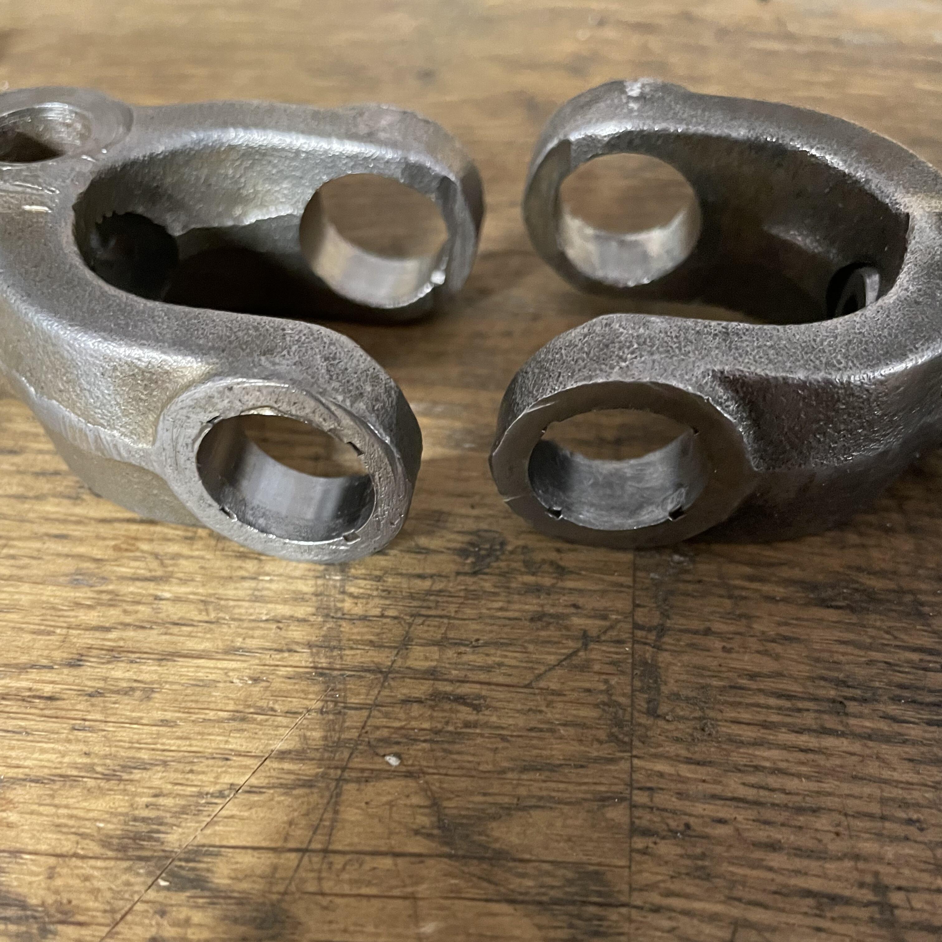
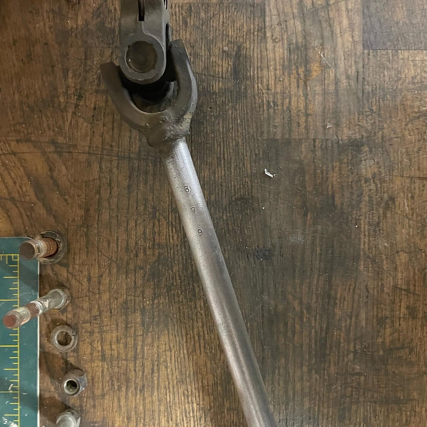
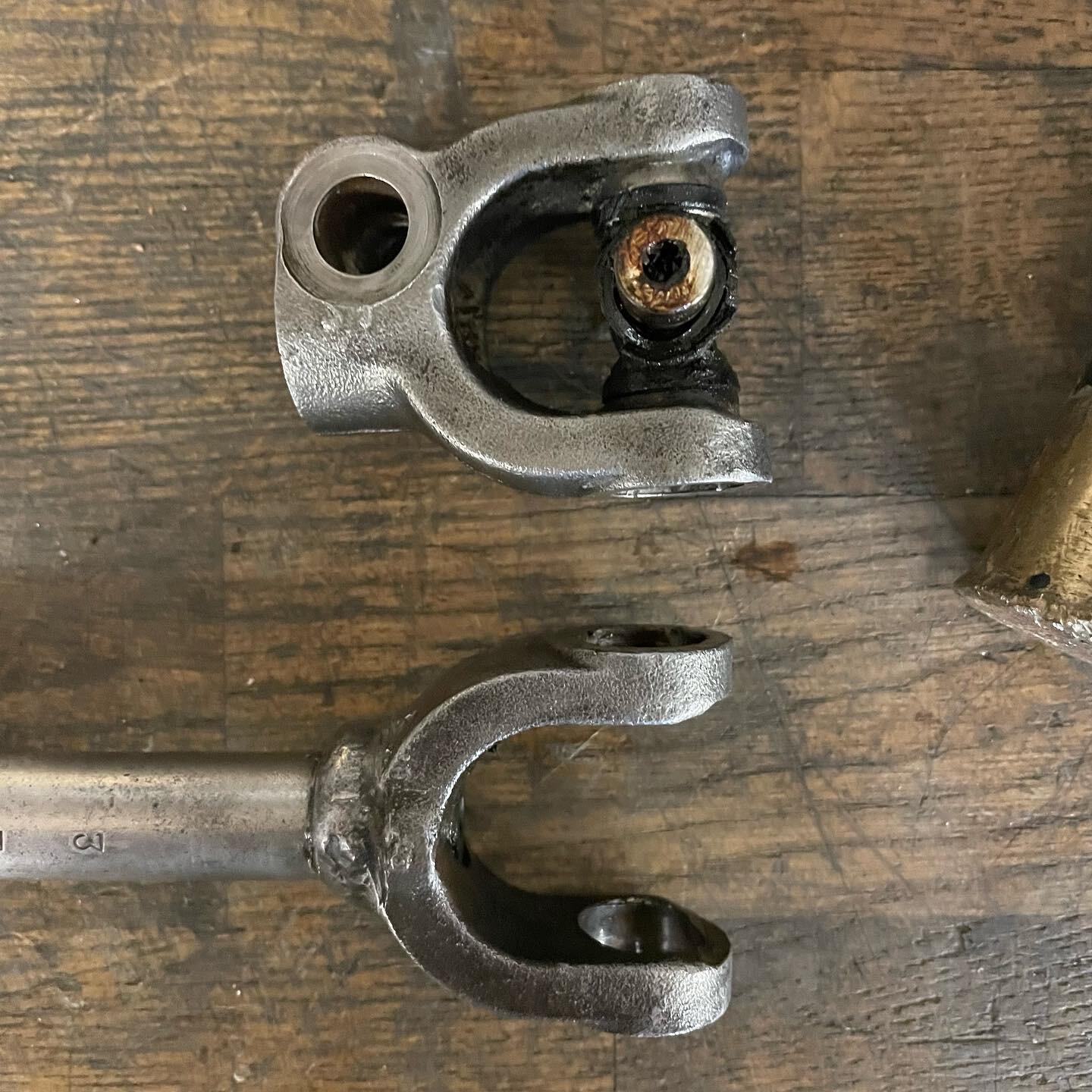
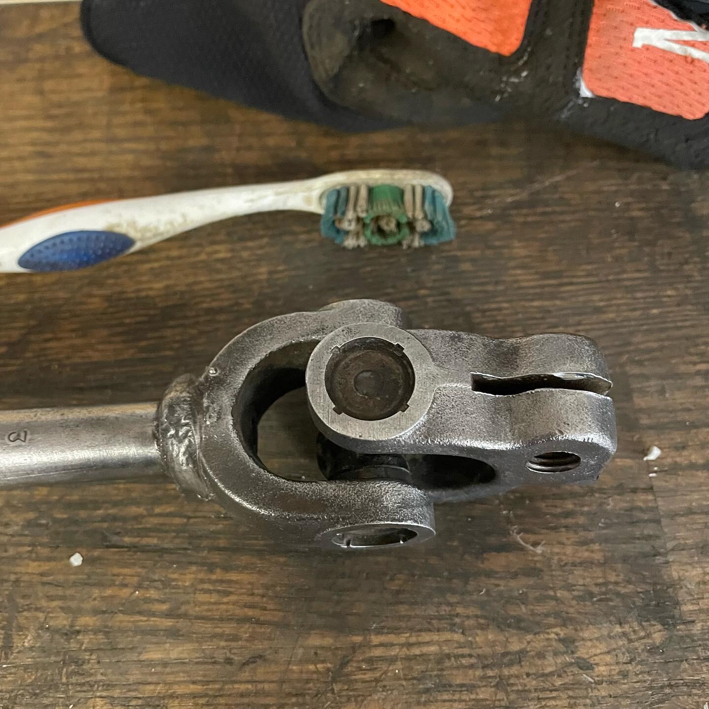
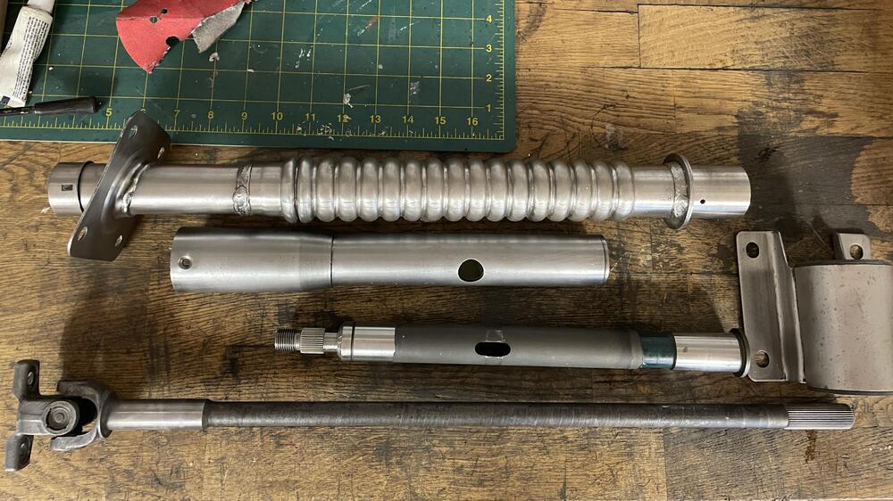
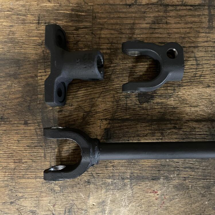
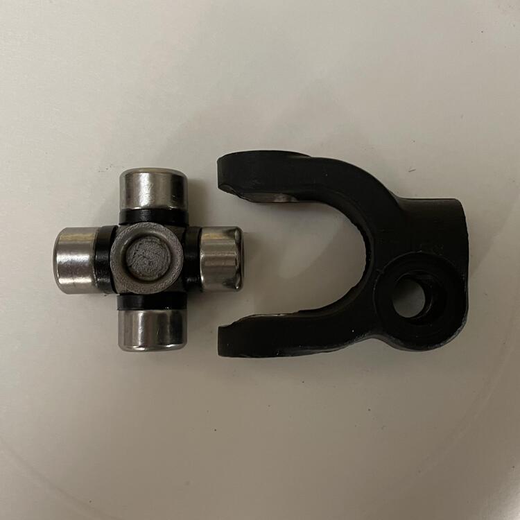
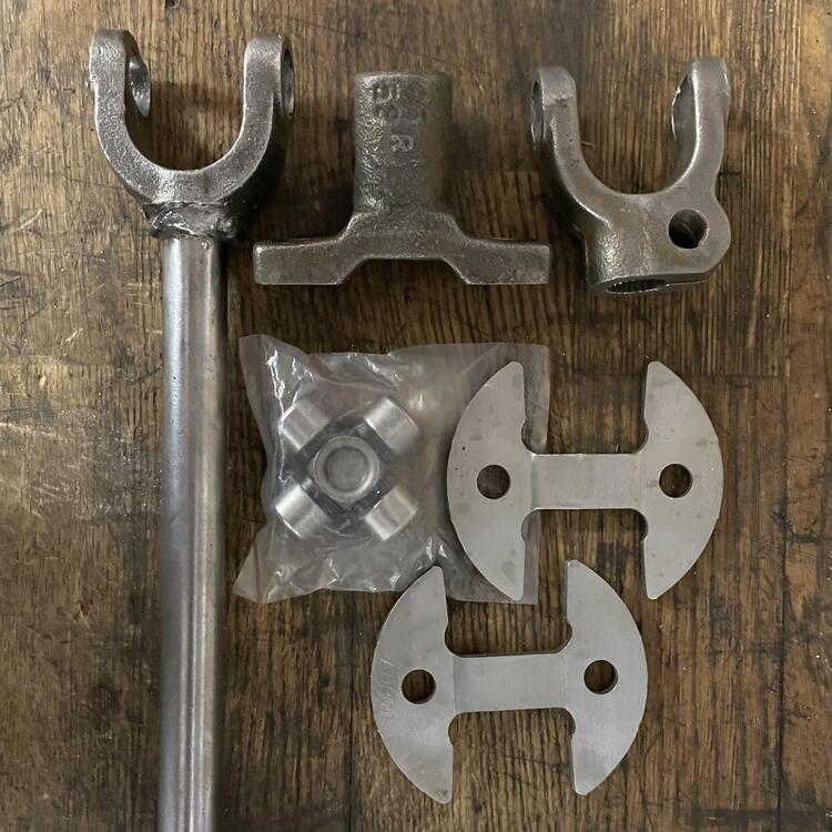
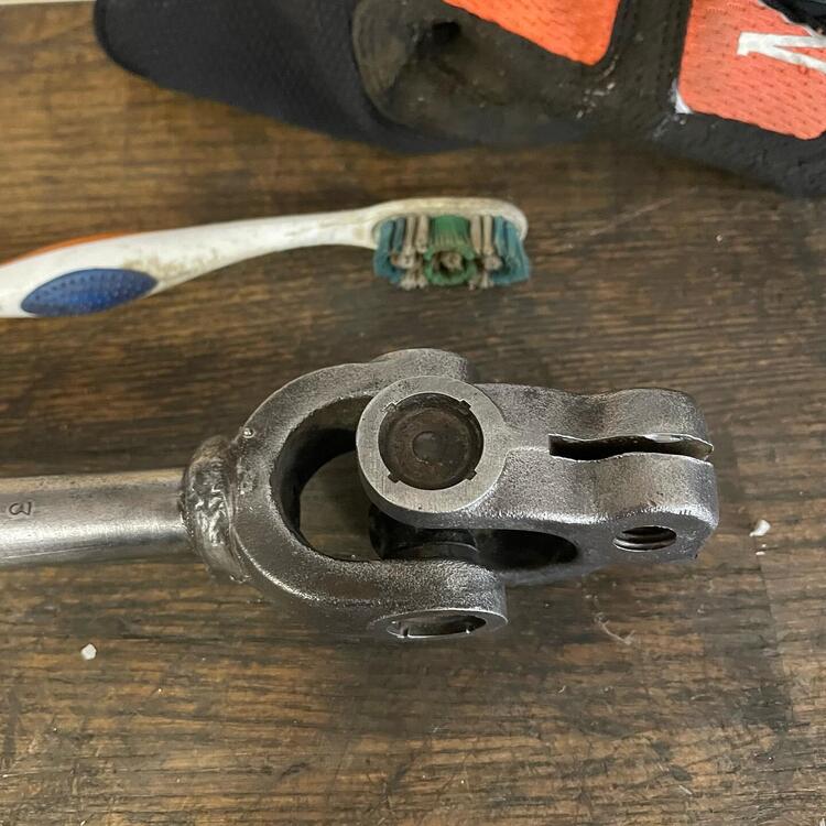
Okay, back to steering… All my original parts are clean and ready for paint. The Land Rover universal joint arrived last night, and new hardware is on its way. The next step is to mic the LR u-joint and make sure it’s a match. Then I’ll paint the shaft parts and get them ready to go back together. The u-joint is from FEBEST, which I have never heard of. Hopefully it’s not garbage. ¯\_(ツ)_/¯ At least this isn’t going to spin a whole lot… Getting the old u-joint out was fun. Since I blew through the top of one of the caps I spent 4 hours and a million different tools to delicately get the remainder out. I dressed the inside of the yokes and got it pretty enough for reassembly. They’re a little bit ugly but not where it matters. I still need to mic them, but I am reasonably certain that I did not open up the holes and ruin the friction fitting.

-
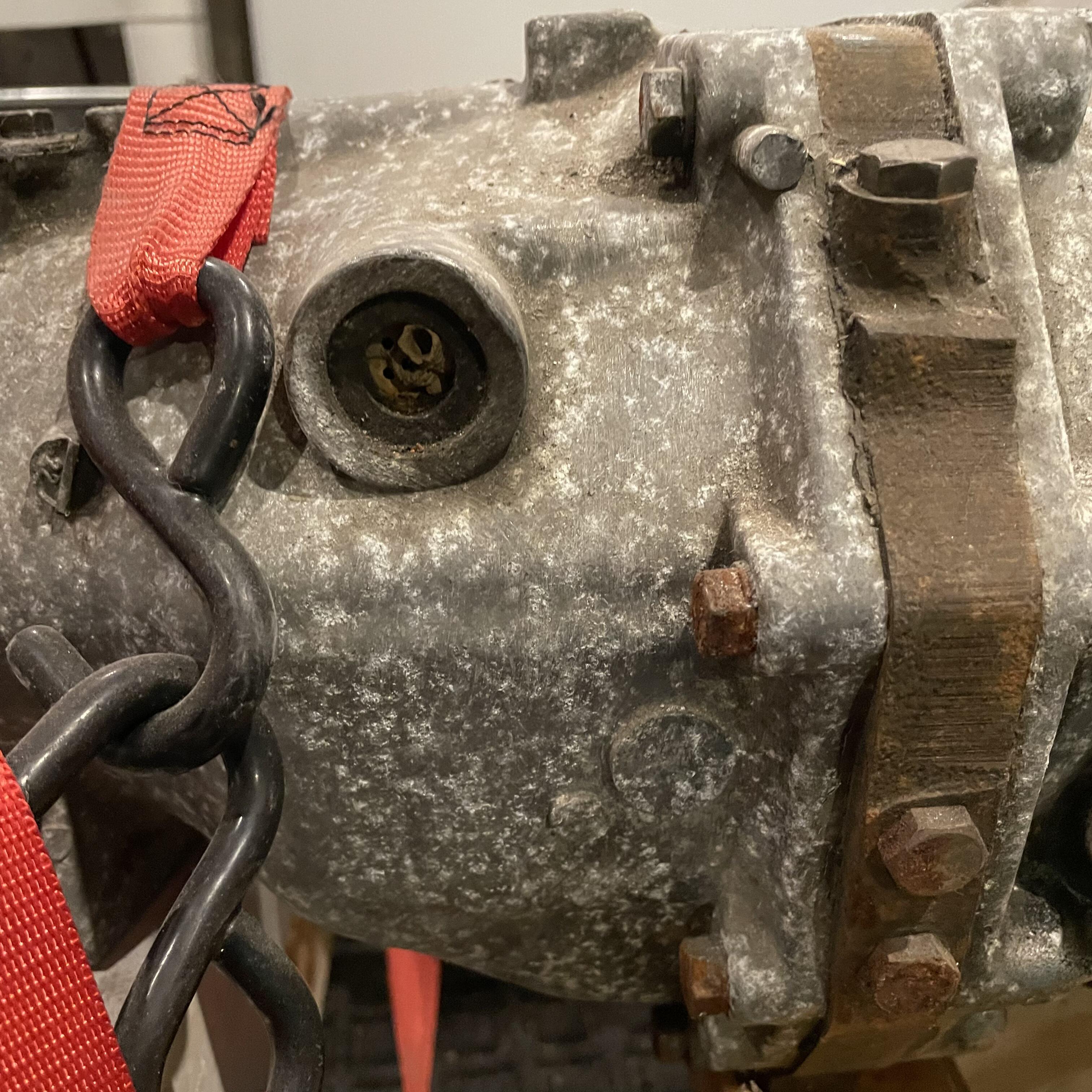
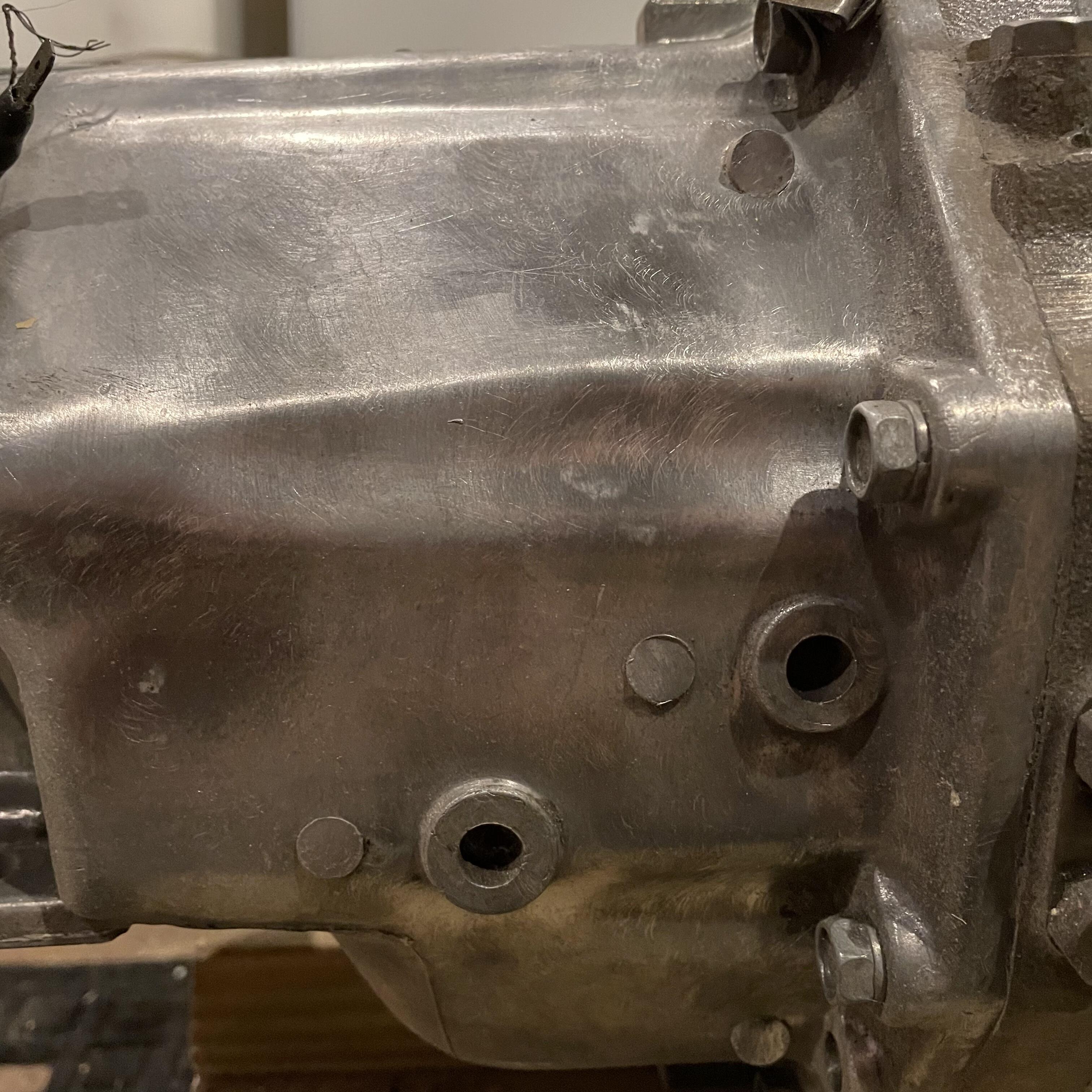
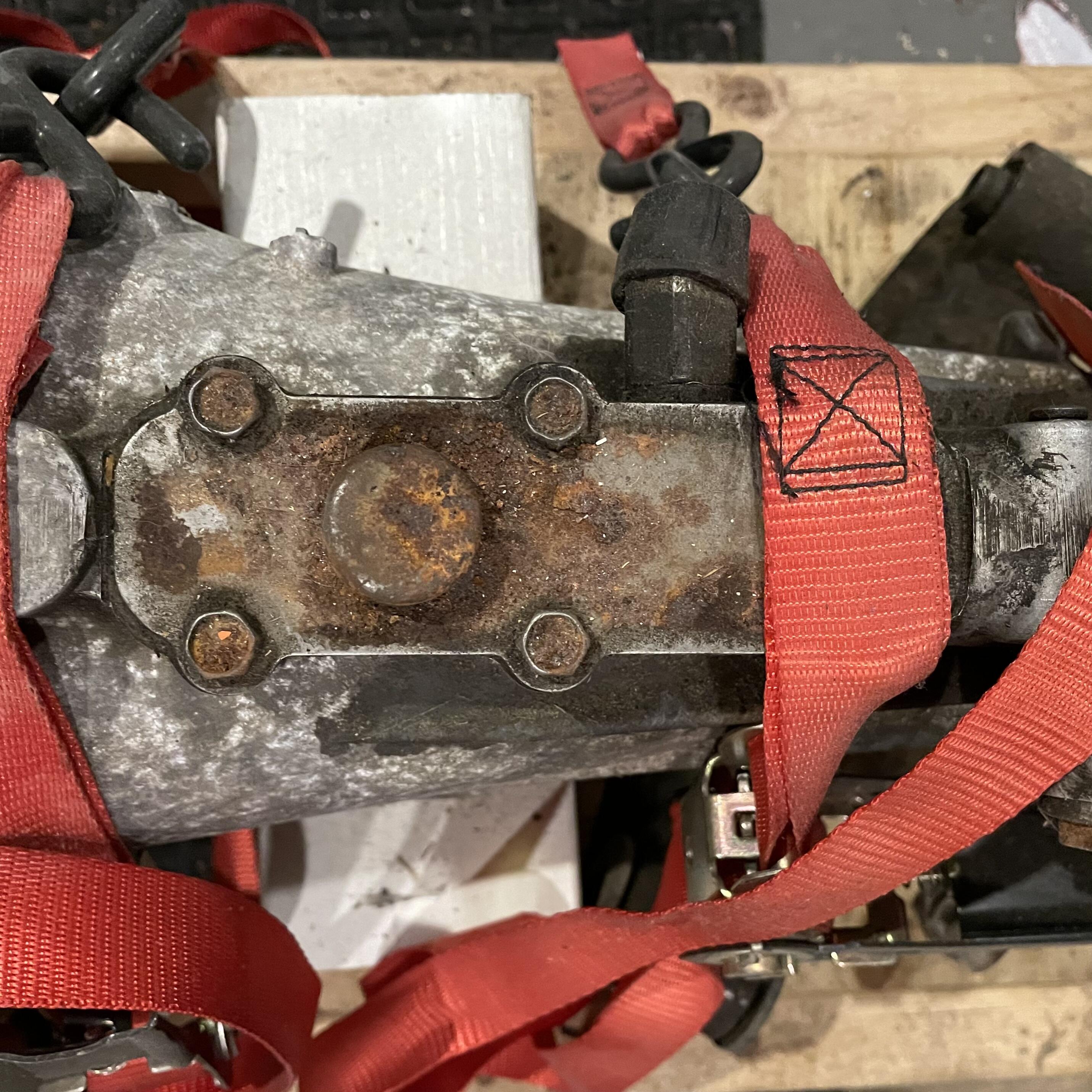
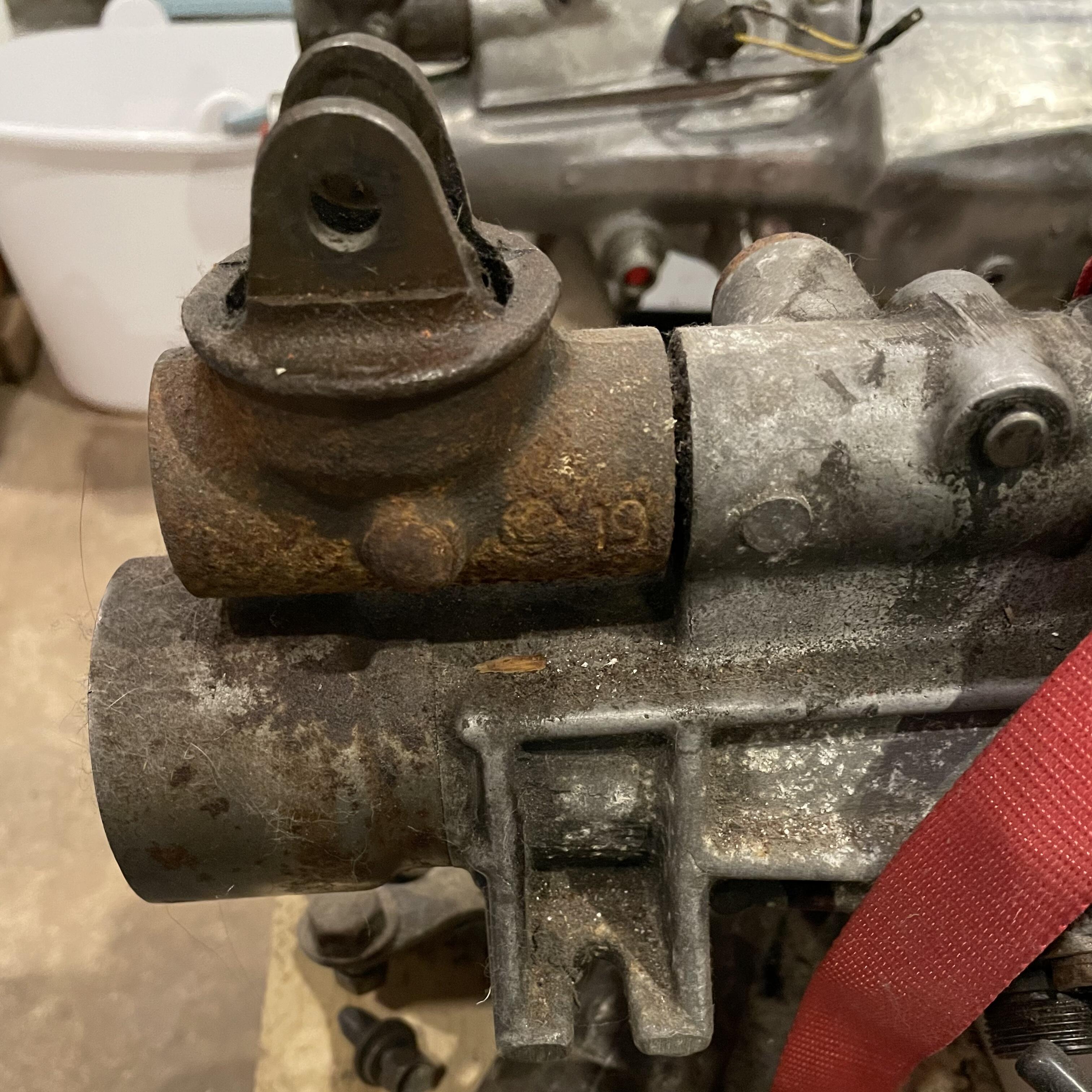
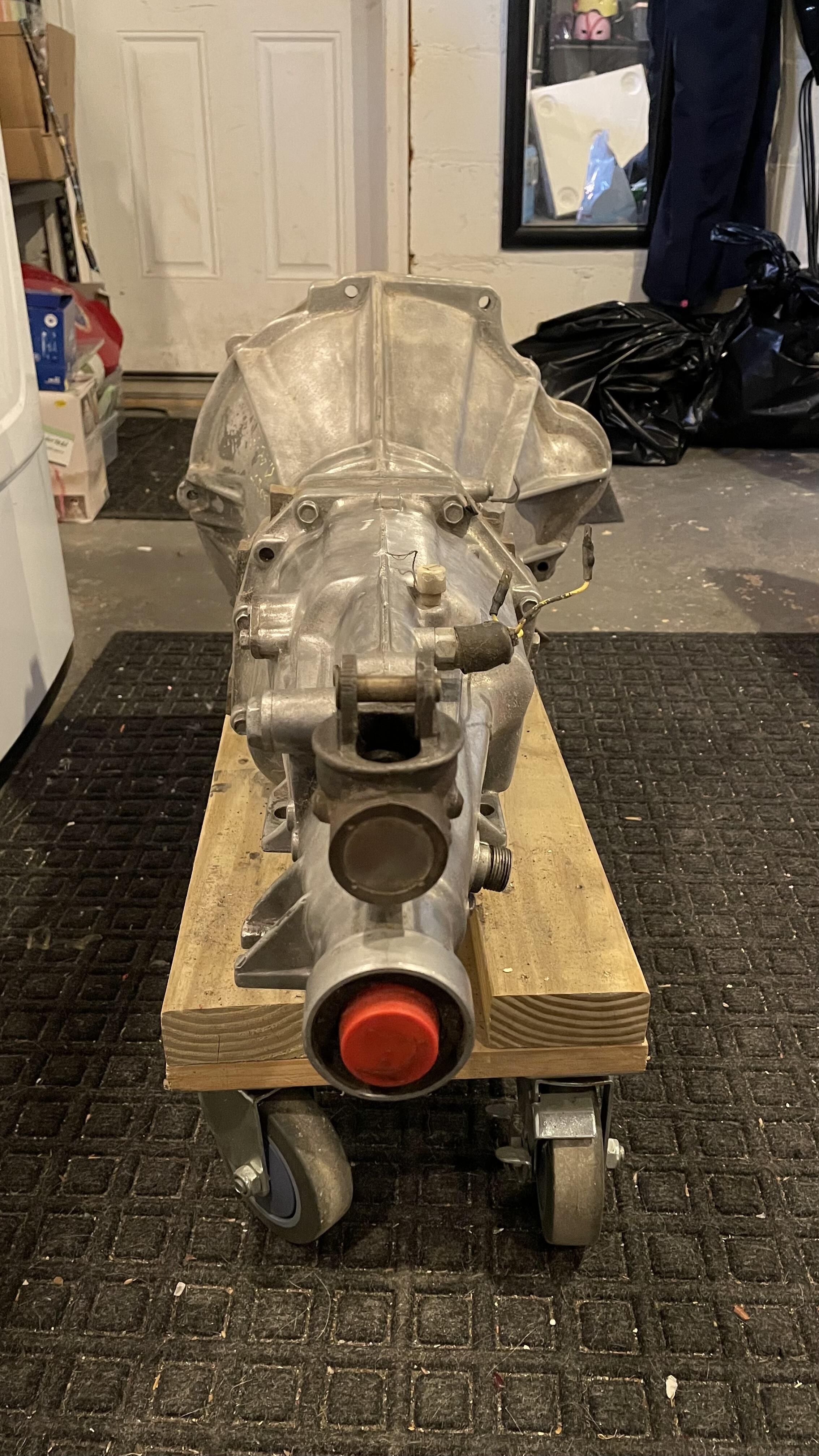
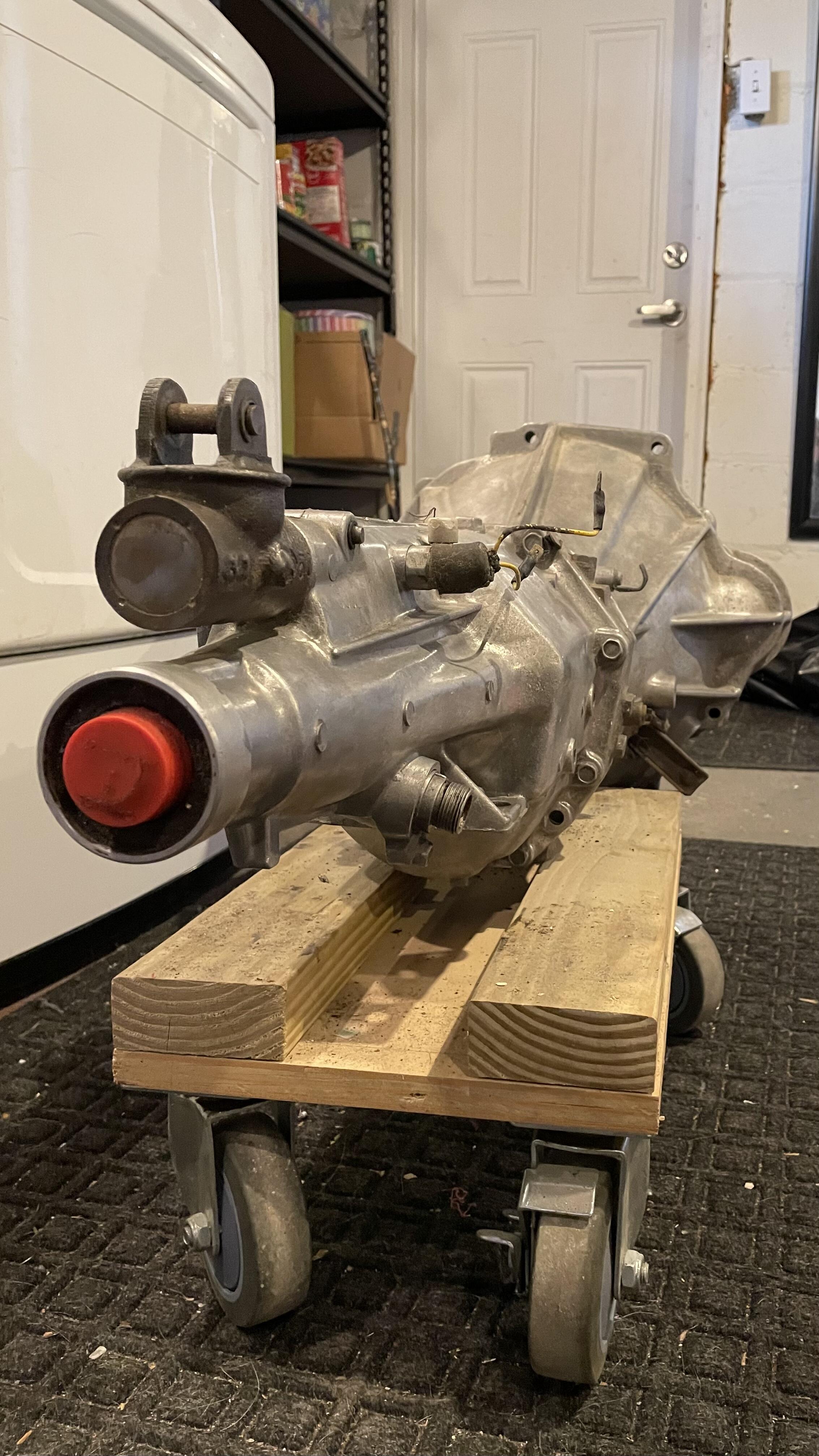
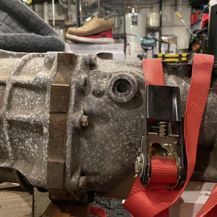
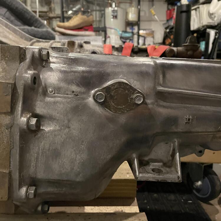
And some photos highlighting the differences between the cases for the 5-speed (shiny) and my (possibly not) original 4-speed (filthy with red tie down straps):


-
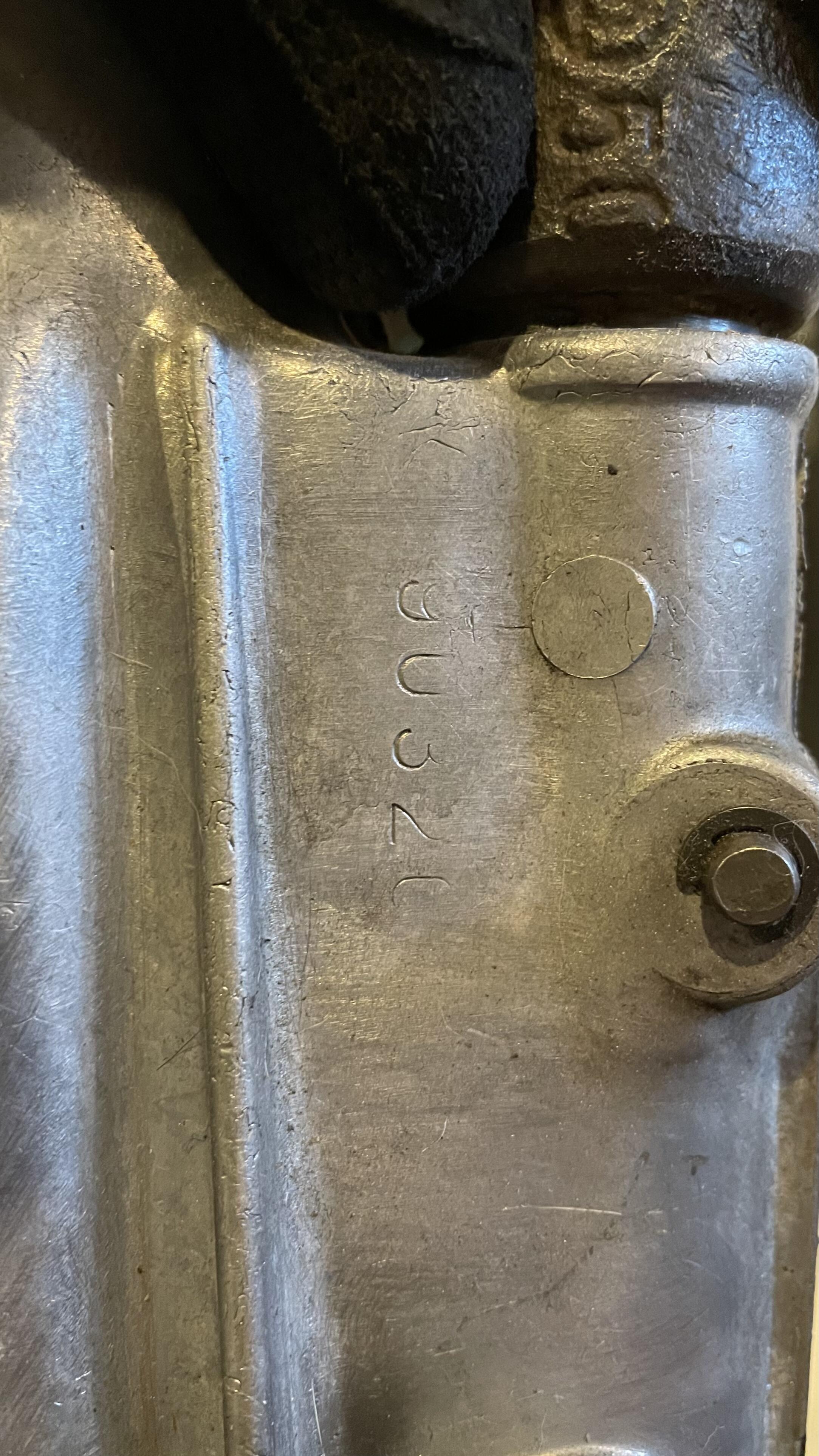
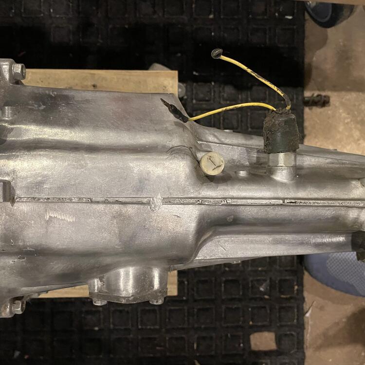
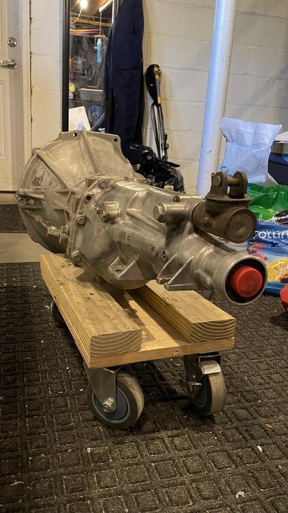
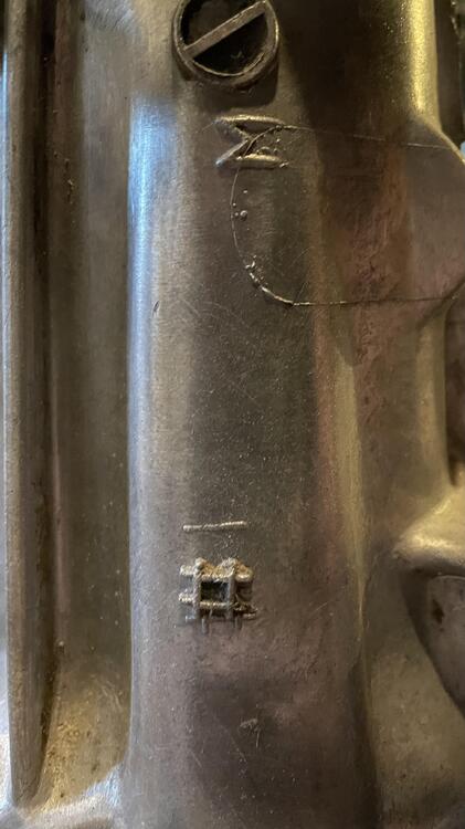
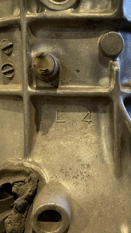
Speaking of the transmission, I took some photos of my 1980 720 5-speed: And the case markings: The #1 indicates the following gear ratios should be in this case: 1 3.592 2 2.246 3 1.415 4 1.000 5 0.813 Same as the stock 4-speed plus an overdrive. Should offset my 3.9 LSD rear end for cruising.


-
Yeah, my dad is doing it for me. He’s close. We ran into some issues with the machinist we went to and our head all needing different problems solved, but we are on track to be done real soon. Soon enough that I need to get the transmission sorted for when the engine shows up.
-
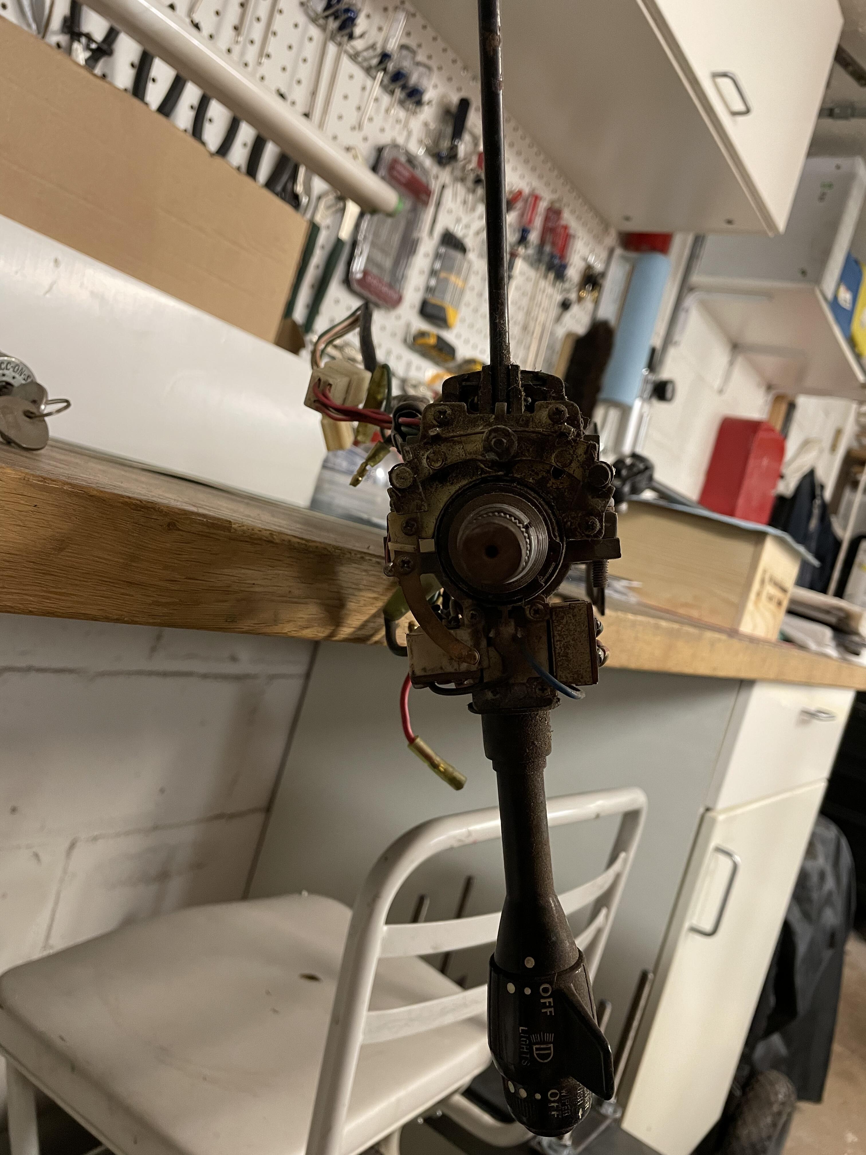
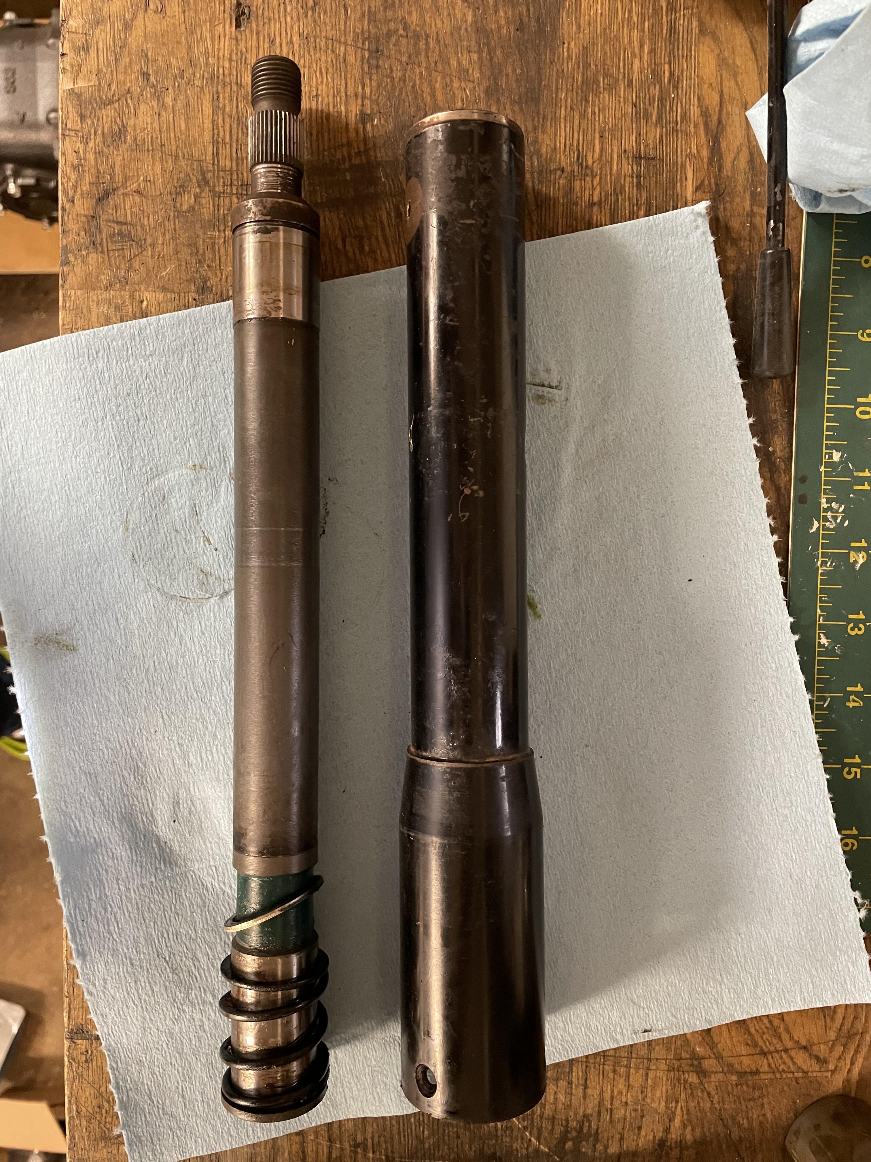
Started cleaning up that steering shaft. The first bit was easy, but I didn’t cut enough of the staking off the last cap and I ended up punching through it. It took 11 times as long to do the last one as it took for the first three. I wanted to be very careful to not ruin anything, so it was a very delicate process of tapping various punches with the brass hammer. In the end I got it apart. Now I just have to wait for the new u-joint. Next step is that wire wheel again, followed by paint. This was black originally, but I’m thinking of going with silver for the respray


-
Oh thank bejeezus! I was having a mild panic attack about having put a lot of effort and money into something that was maybe going to be a boat anchor.
-
Sorry to resurrect an old post from a semi-old thread, but I’m curious what makes you say the first gear ratio on the truck transmission is a stump puller. It’s identical to the stock 4-speed ratio (as are 2, 3, and 4), according to ZHome. I’m concerned about this as this is the transmission I’m intending to put into my ‘73 (a 1980 720 5-speed with case #1).
-
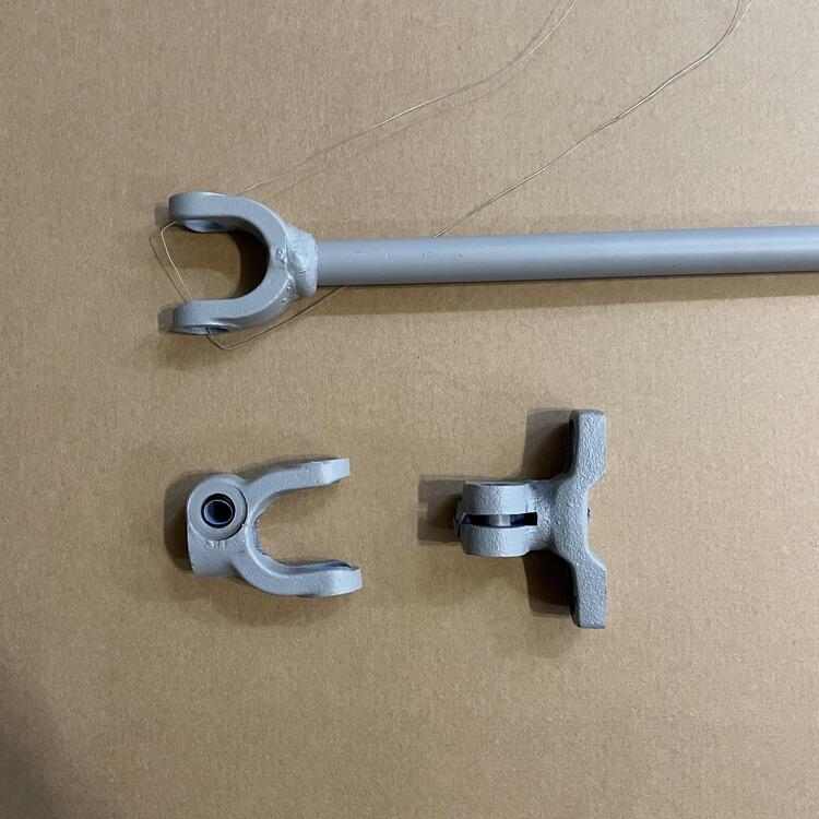
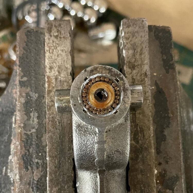
Well, I thought I’d be smart ad clean up my steering shaft with a wire wheel, but I wasn’t thinking about what I was doing and I hit the rubber seals on my perfectly good universal joint and ripped them off. Now I have a problem. I know you can get a u-joint from a Land Rover that fits in these staked shafts from later 240zs, but it’s the restaking that is the issue. I can’t find a machine shop willing to do anything with a staked u-joint, including removing them.