Matthew Abate
-
Posts
1,187 -
Joined
-
Last visited
-
Days Won
16
Content Type
Profiles
Knowledge Base
Zcar Wiki
Forums
Gallery
Events
Downloads
Store
Blogs
Collections
Classifieds
Everything posted by Matthew Abate
-
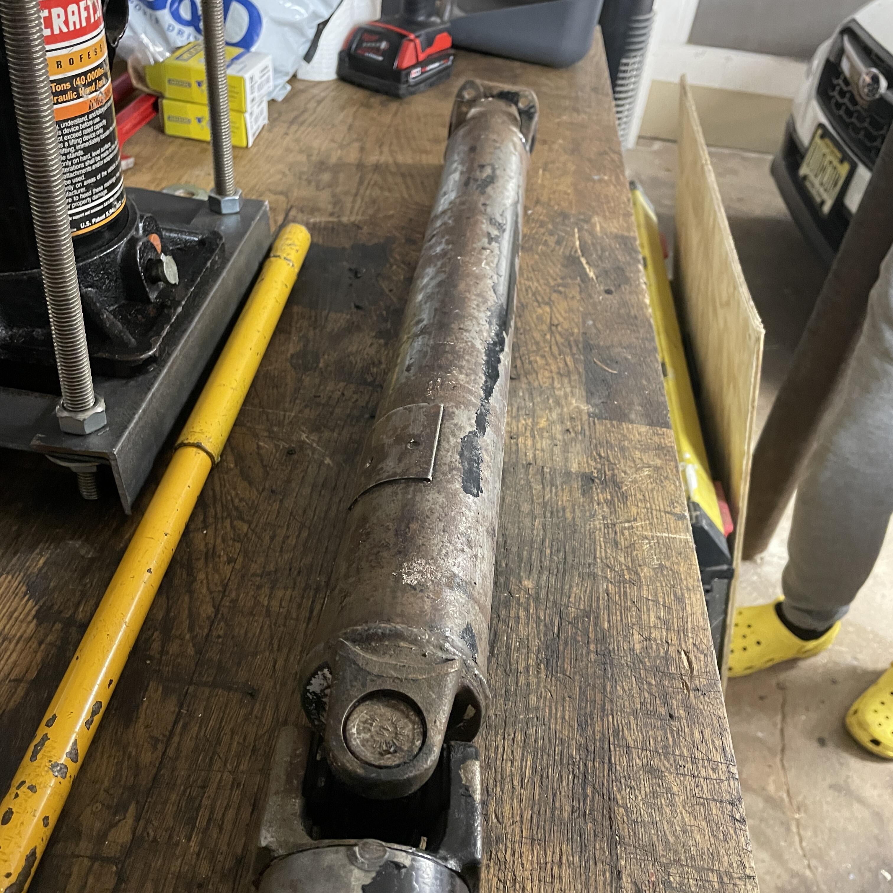
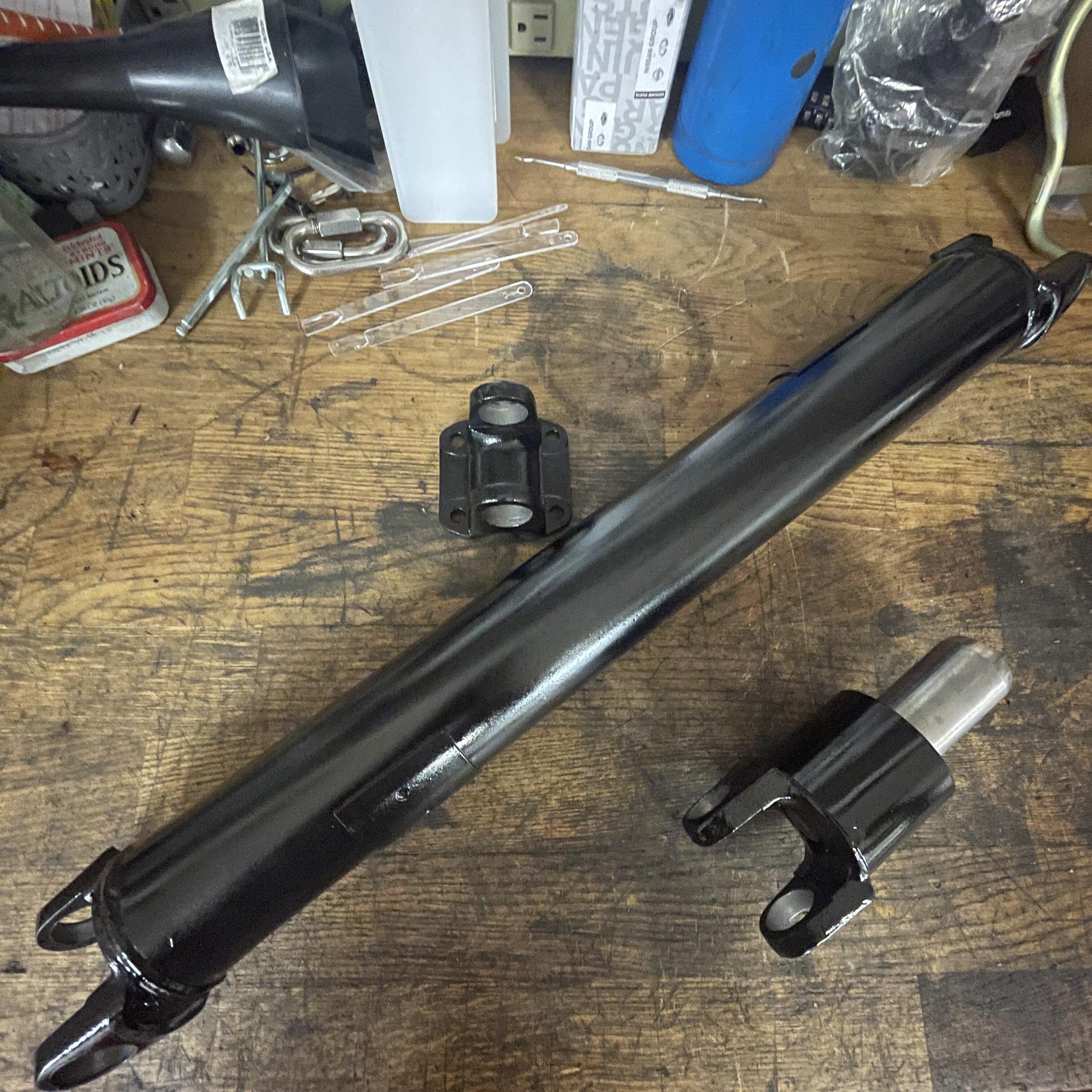
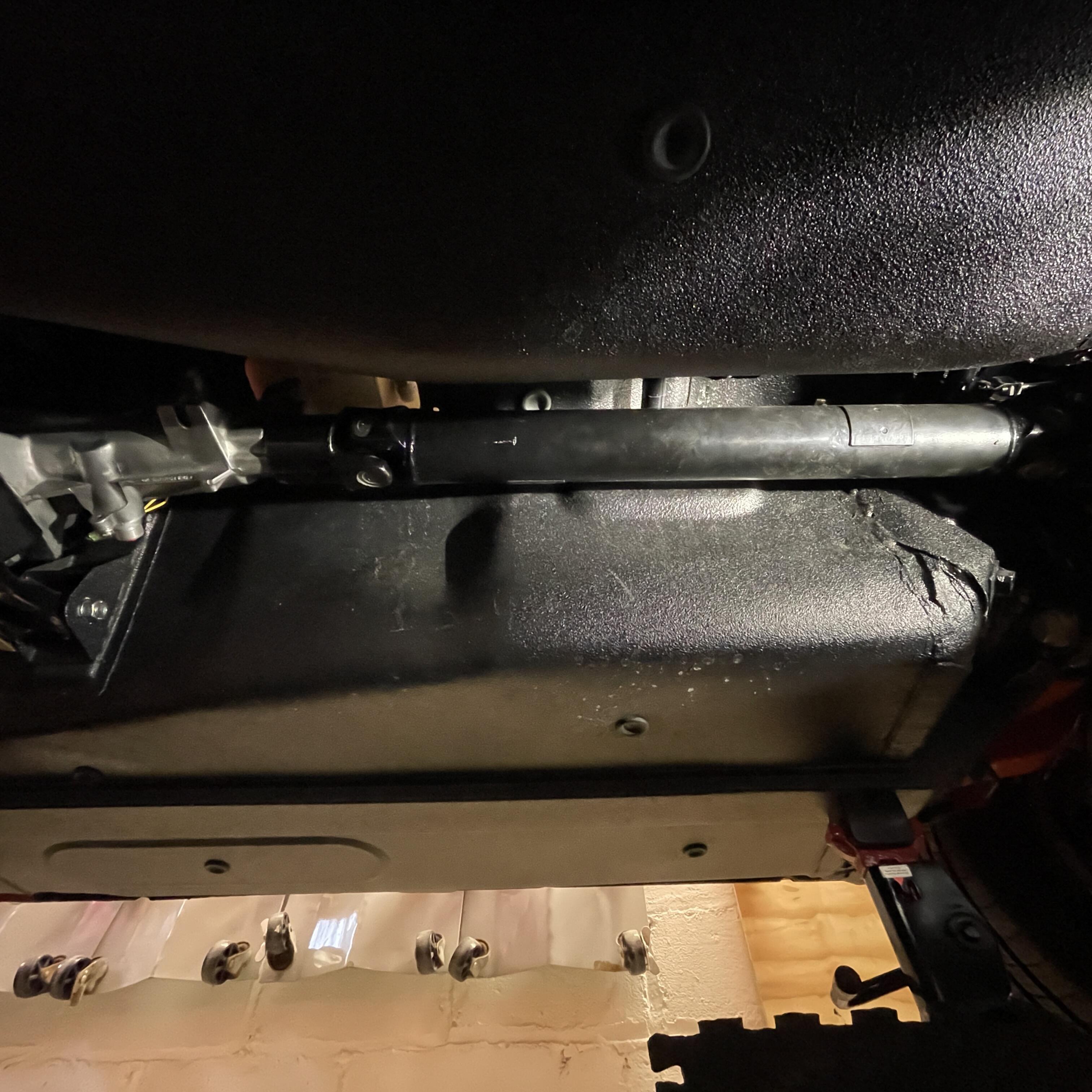
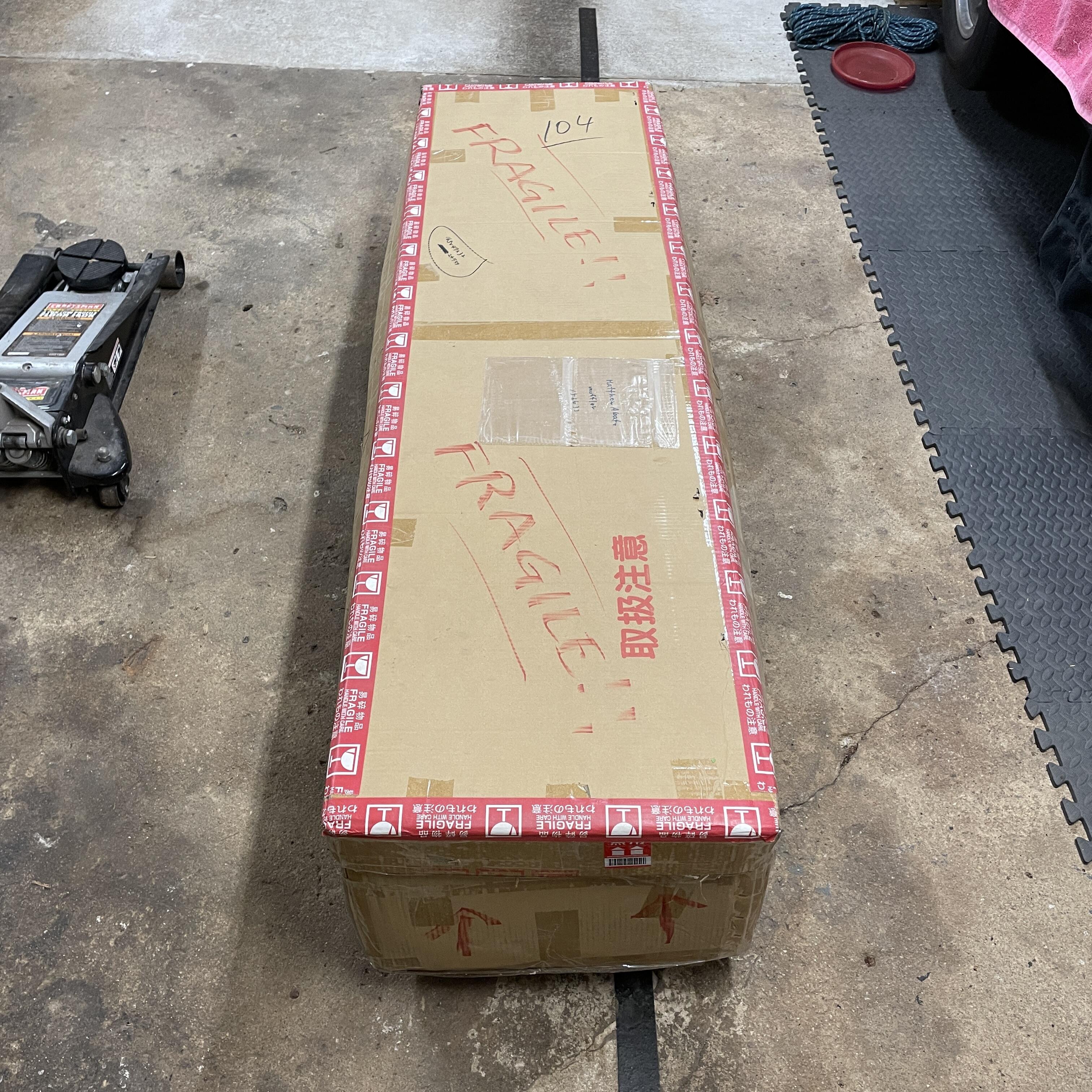
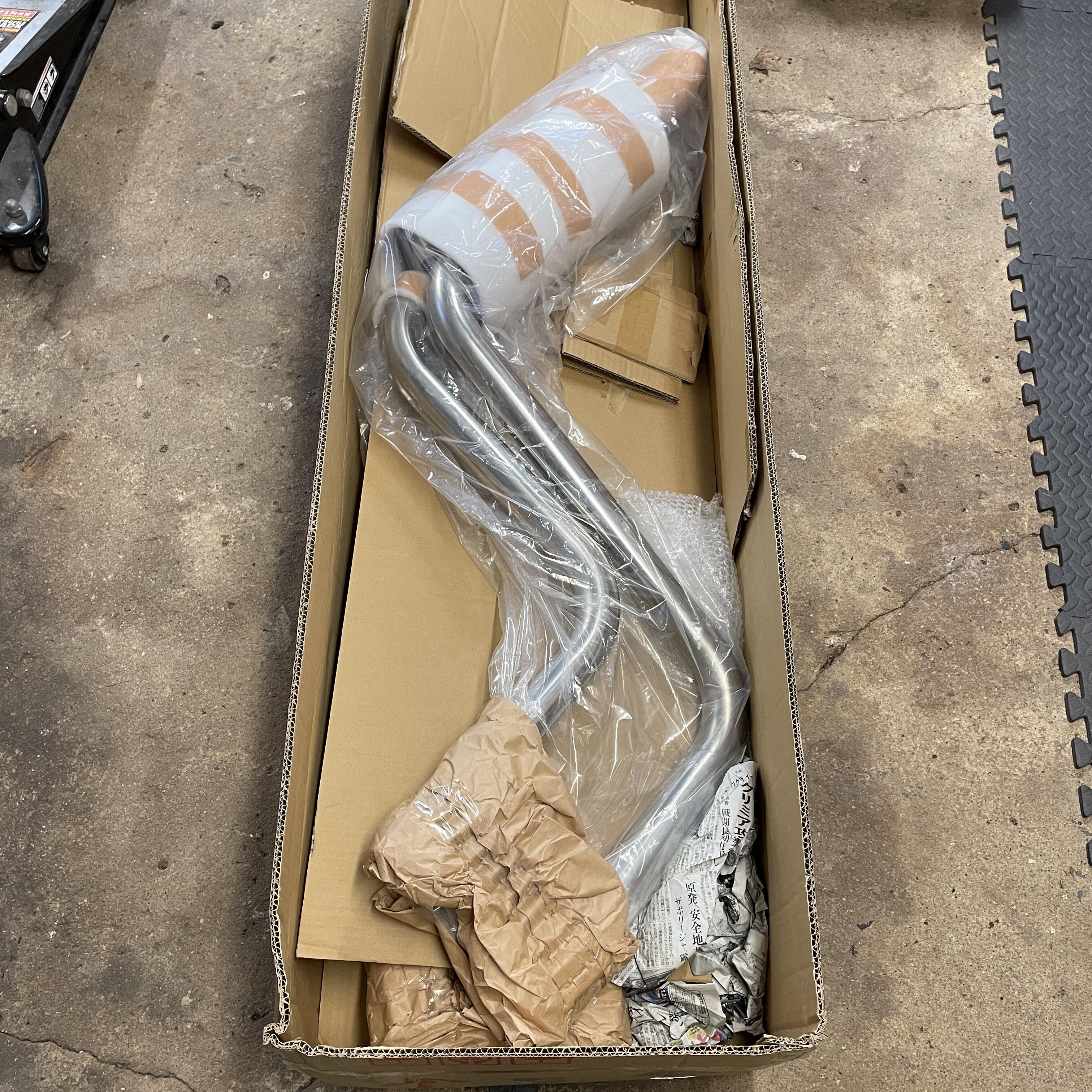
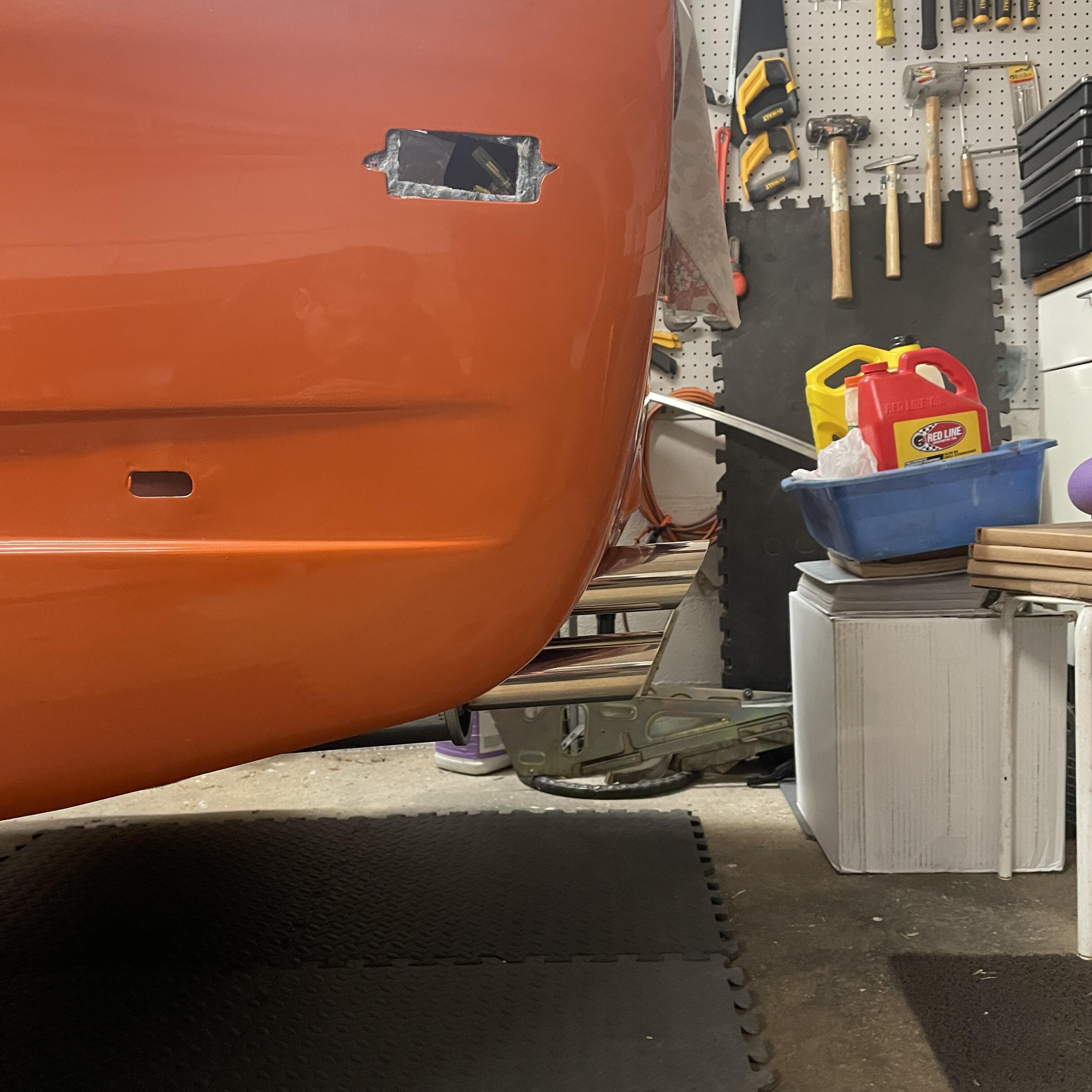
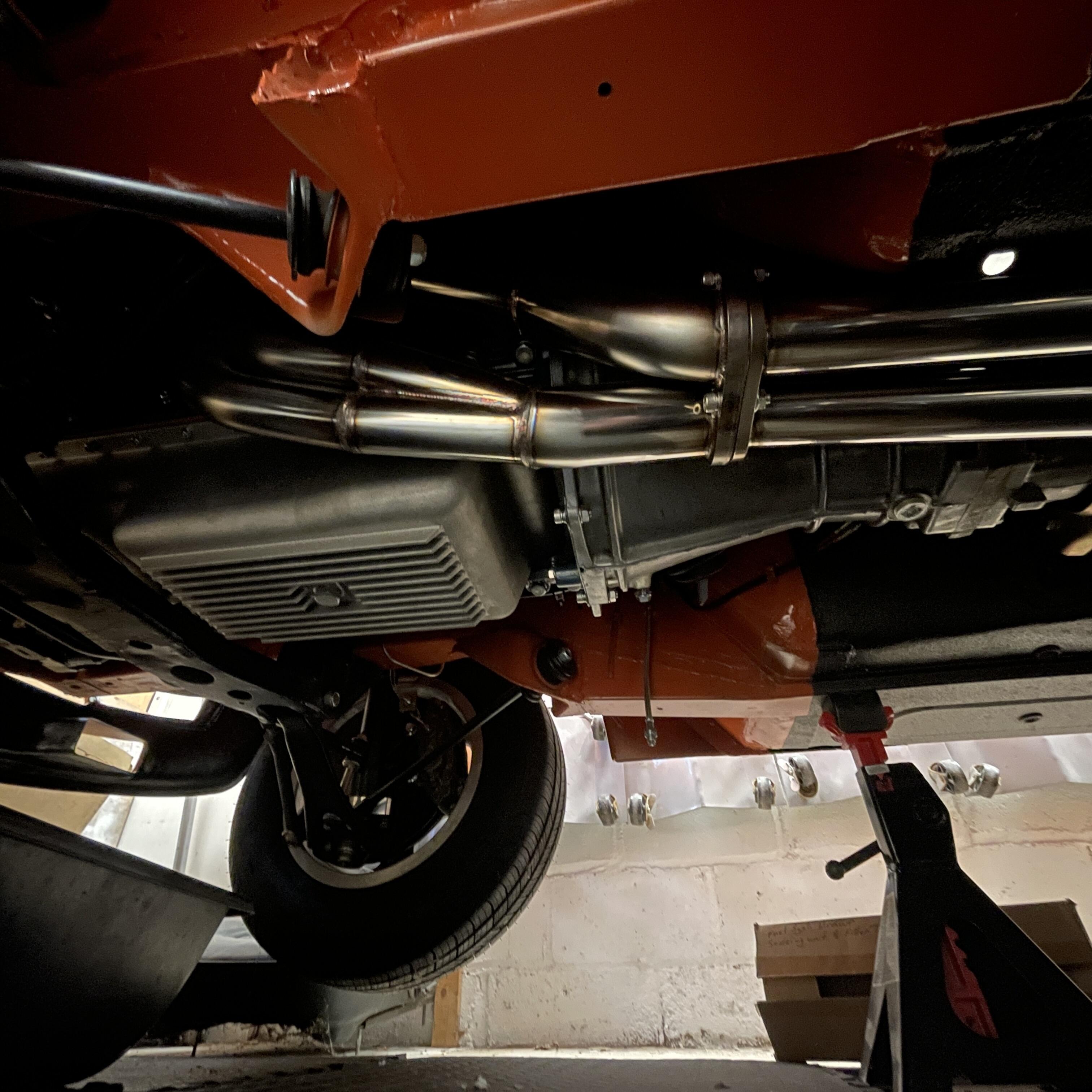
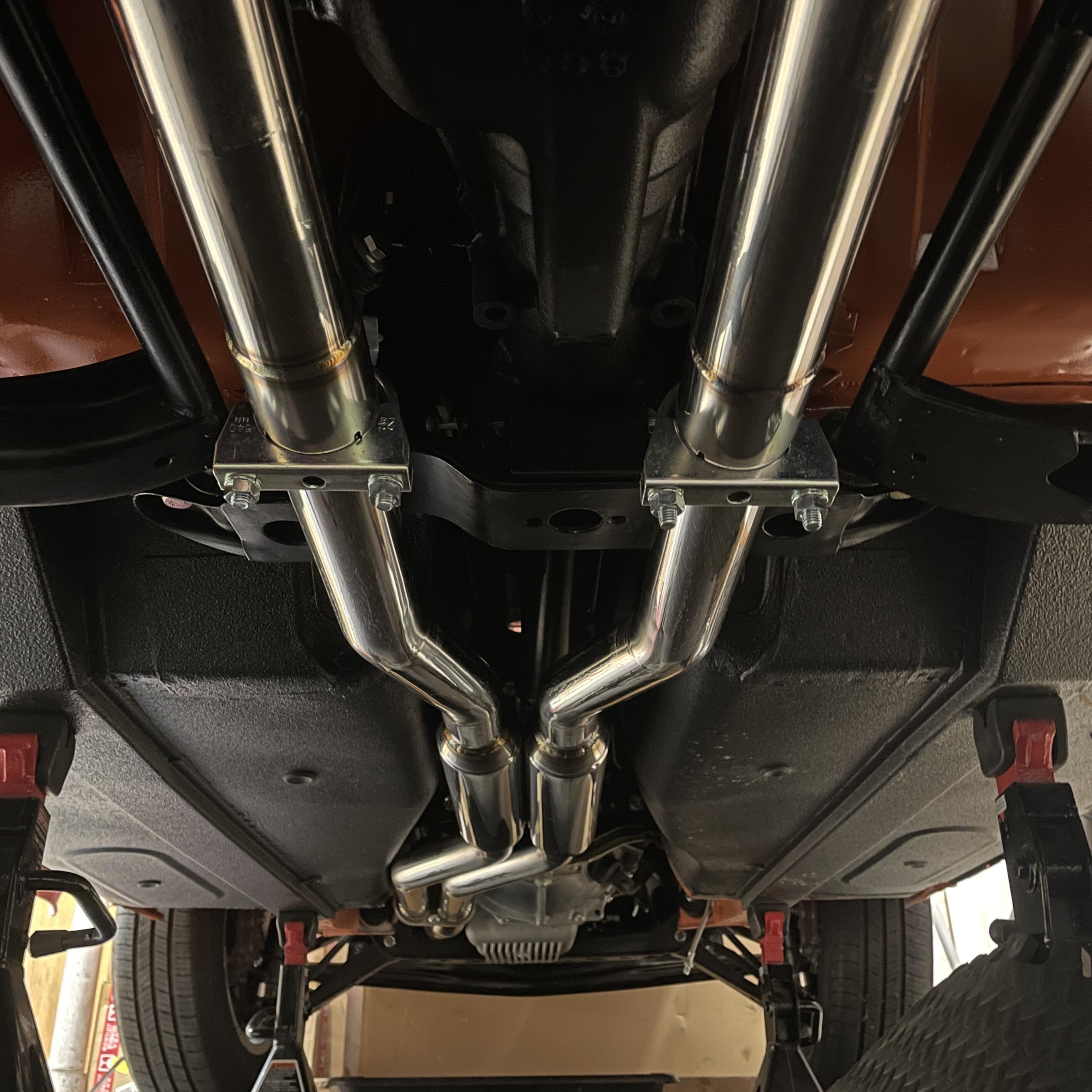
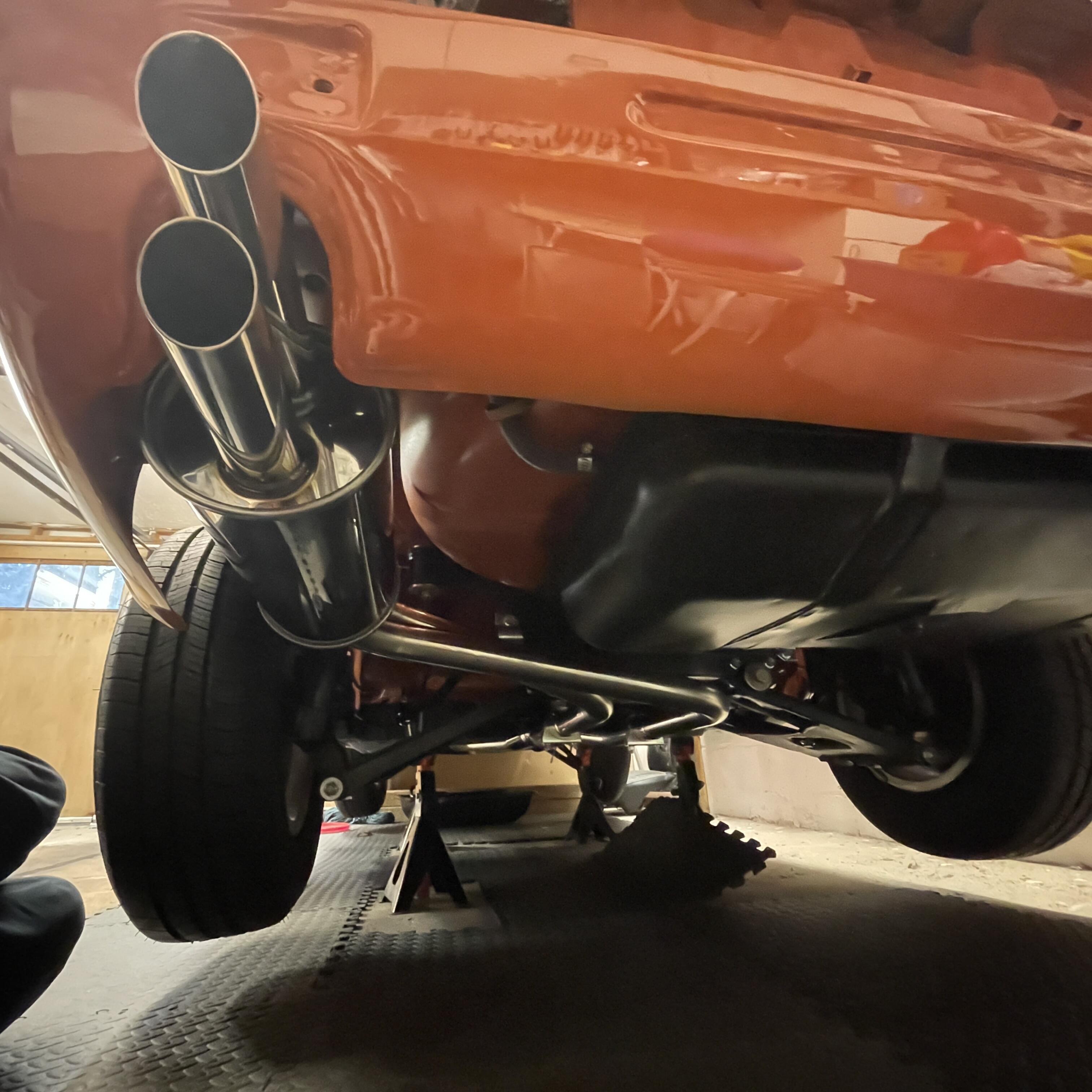
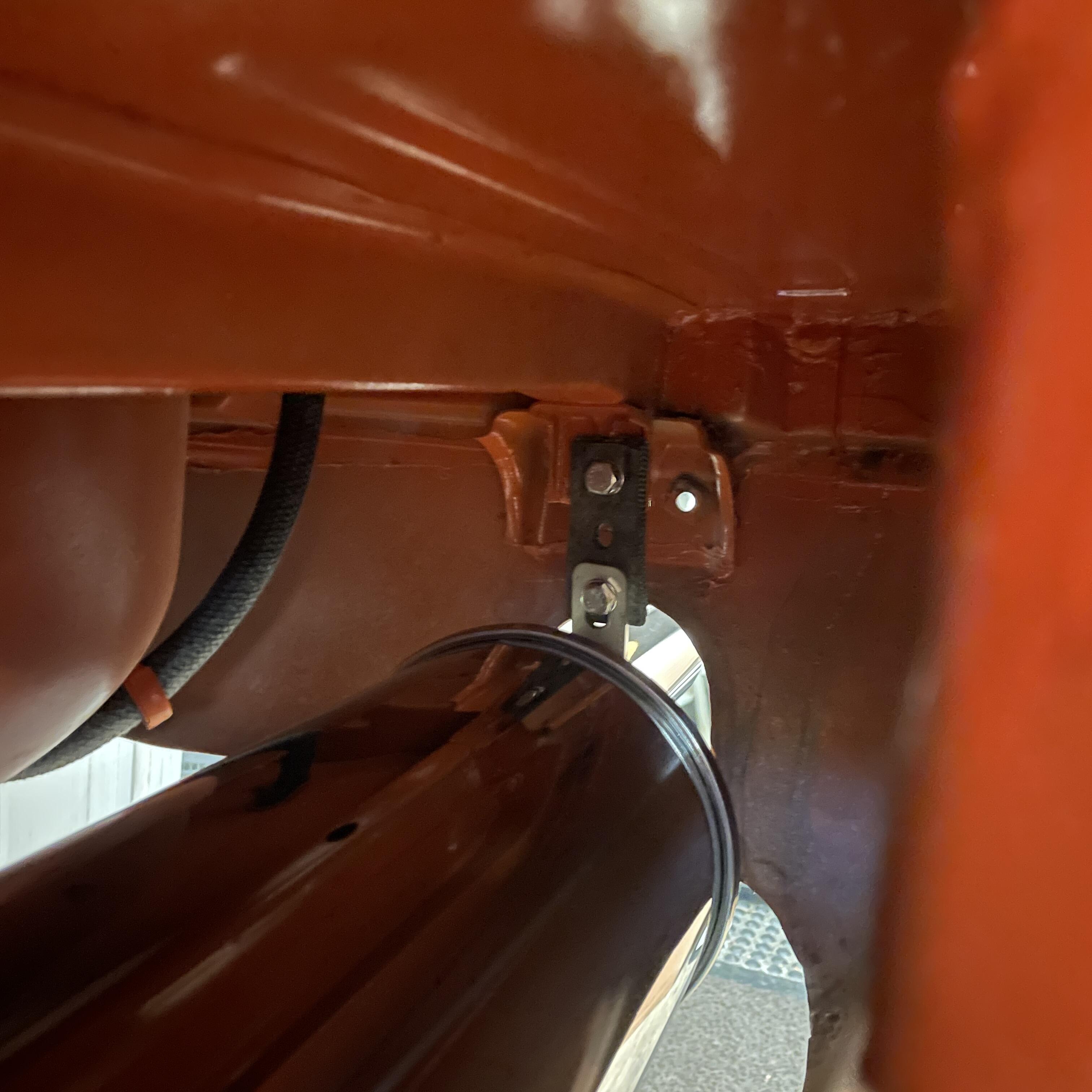
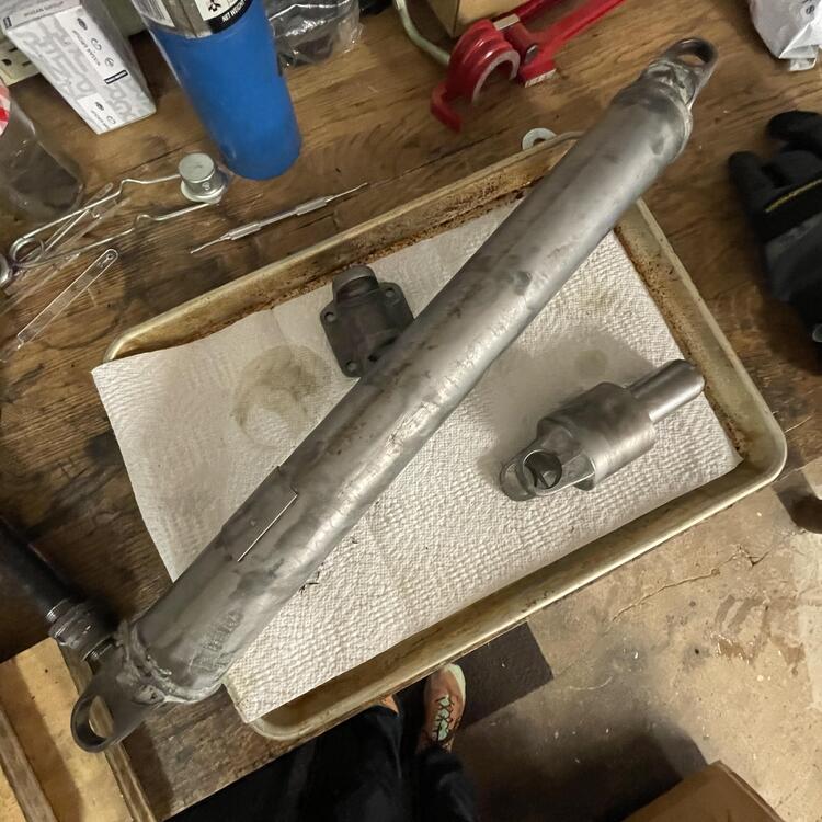
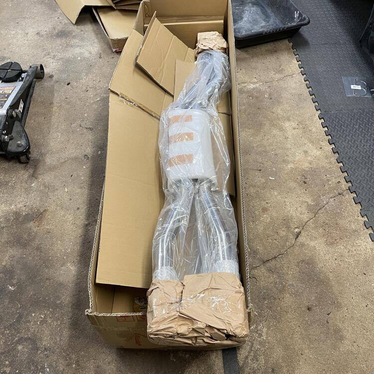
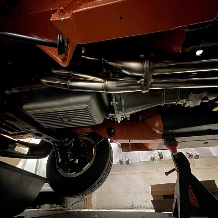
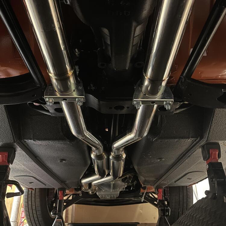
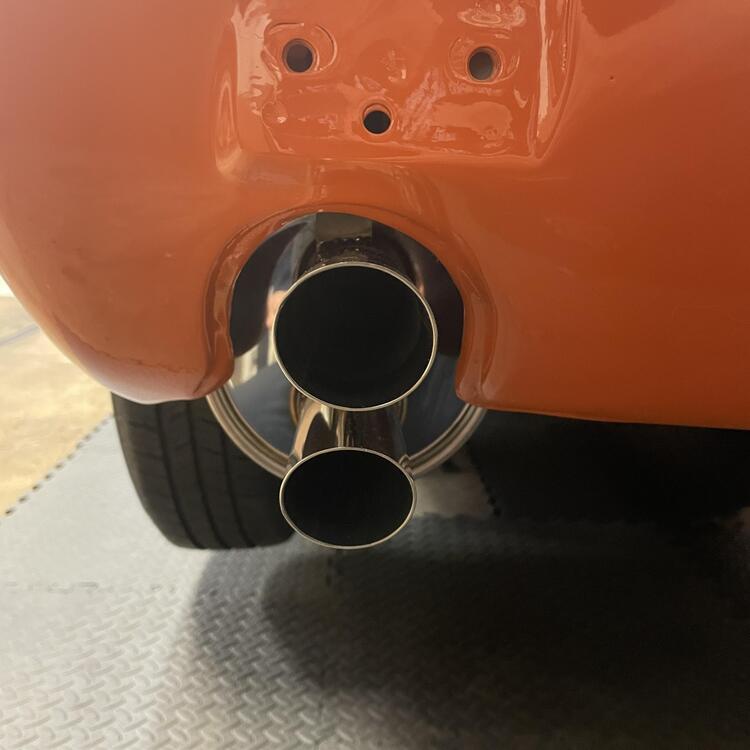
Couple of updates.. Other than the half shaft, the drive train is complete. Restoring the driveshaft was simple. I had read somewhere that the u-joints are NLA, but I found them in two seconds at Z Car Depot, so I don’t know what that’s about. *** I swapped the flange from my Datsun diff and put it on the Subaru way back, so it went right in. Hanging the rest of the Spirit Garage exhaust system really felt like reaching a summit. Maybe it’s because now everything I need to do start the car is in the engine bay, which feels more doable conceptually. The system went in really easily except for a few minor things: The hanger tab in front of the muffler is about an inch too far forward, so I had to put a bolster on the bolt to take up the slack. I don’t love how it looks so I plan to get two that are half as long. That should clean it up a little. The pipes hang a little low at the differential crossmember. I had expected them to tuck tight up into the relief on either side of the, but if I lift it any higher it hits the differential. That’s a little bit of a bummer, but it’s similar to what I’ve seen on some others. Also, the exhaust tips are a little close to the rear valance. I could get different hangers, but I think it will be okay. Still plenty of time to think about that. For hangers I opted for some universal pieces from Walker Emissions (36273 and 36274) that I just cut to an appropriate length. So now I just need some stainless clamps and some acorn nuts to protect them from random debris. Now back to the engine bay.


-
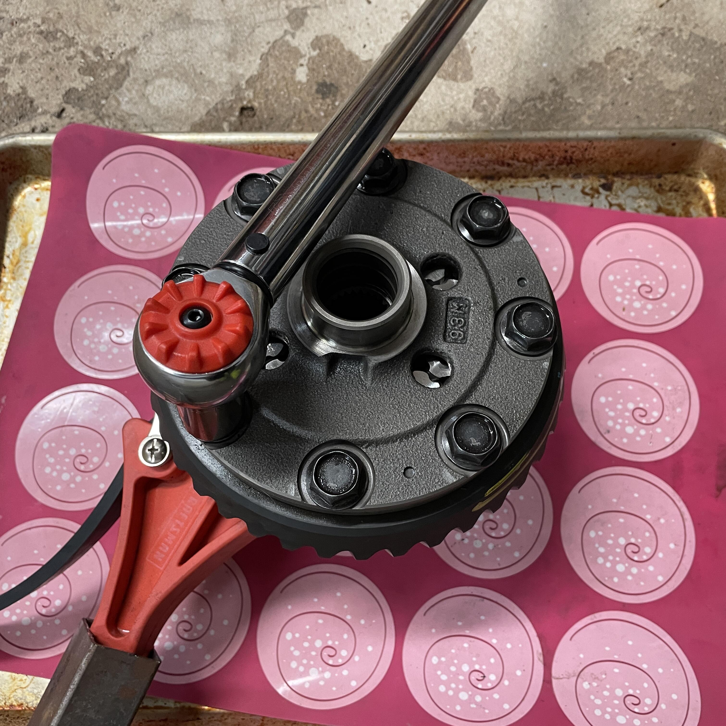
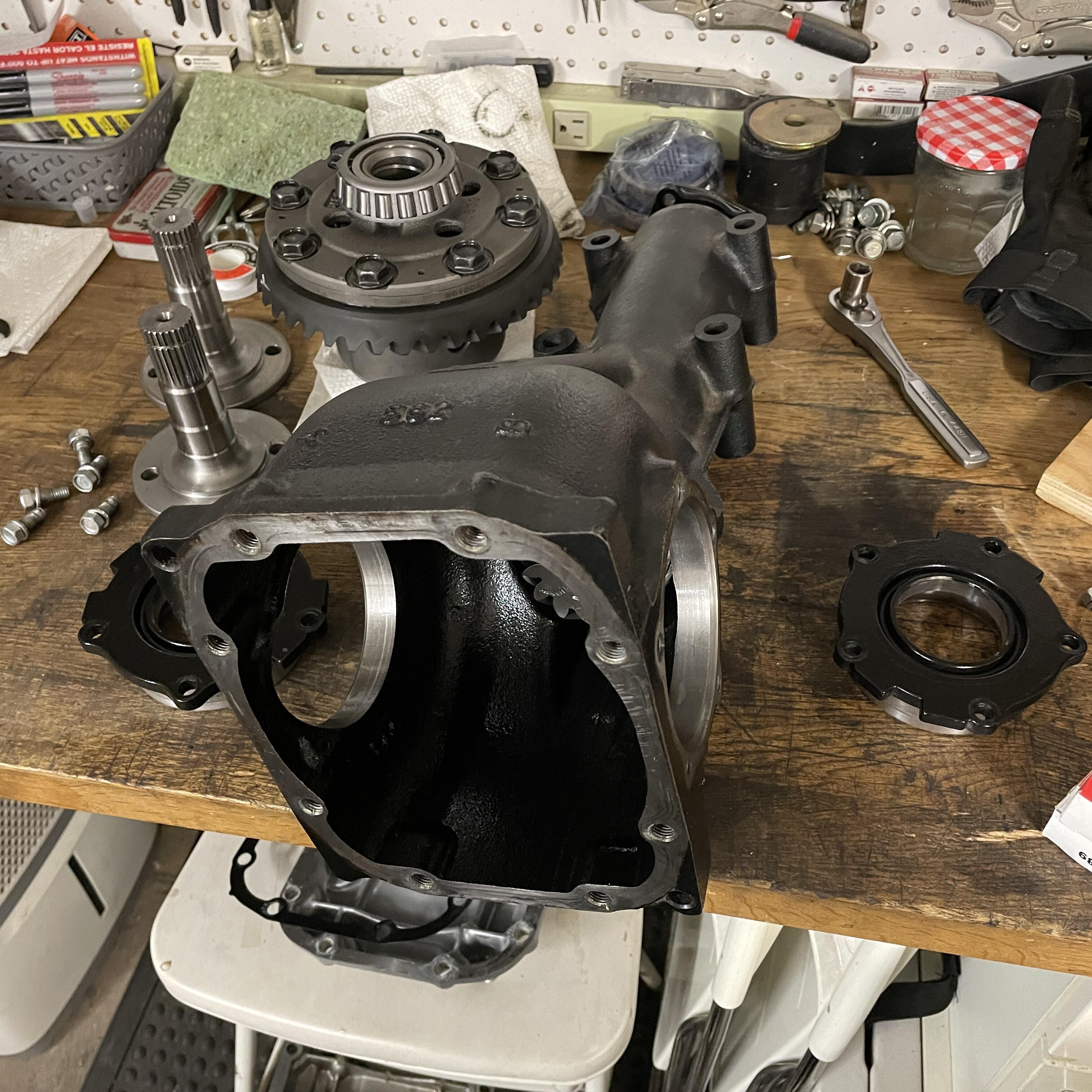
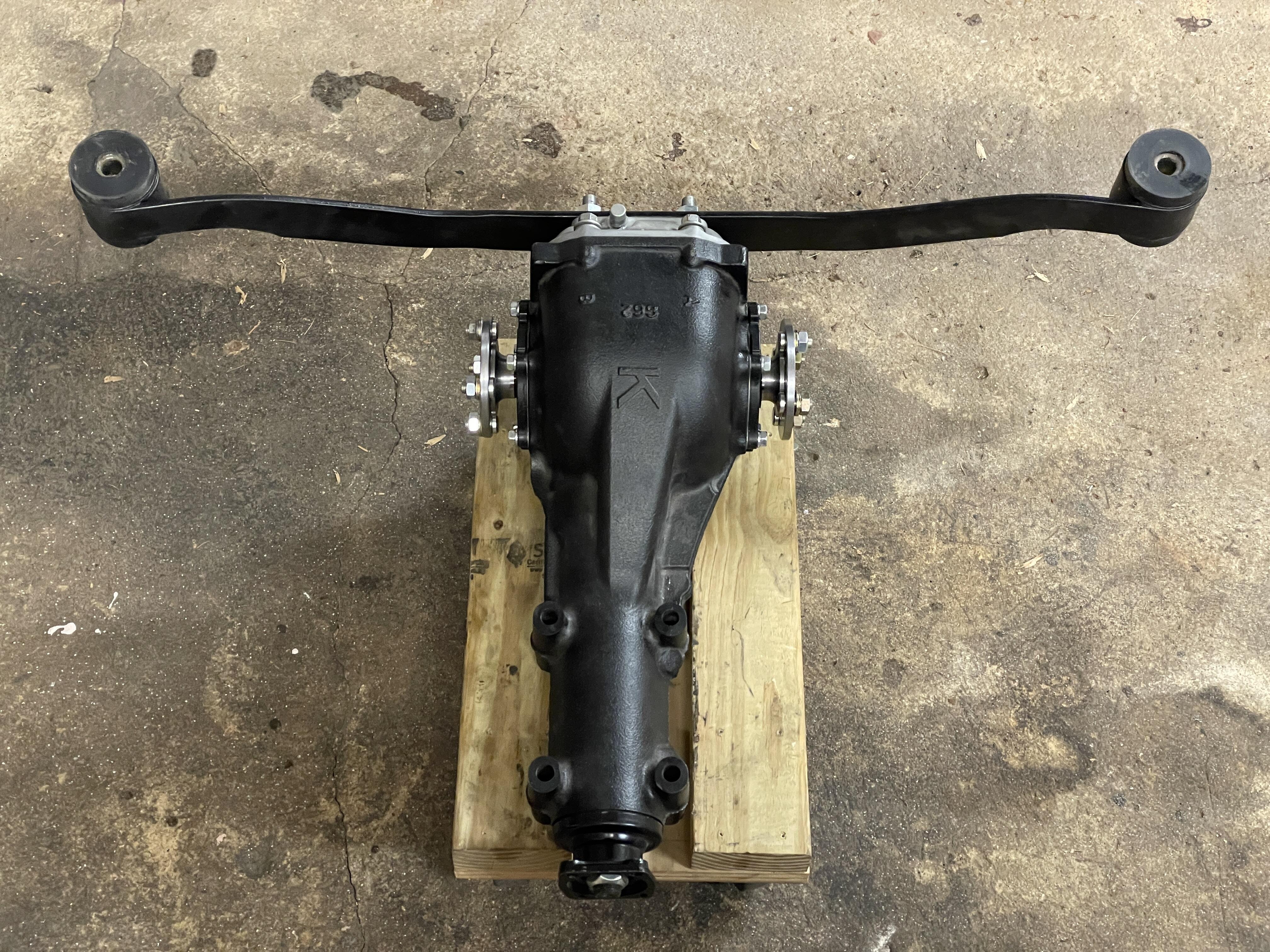
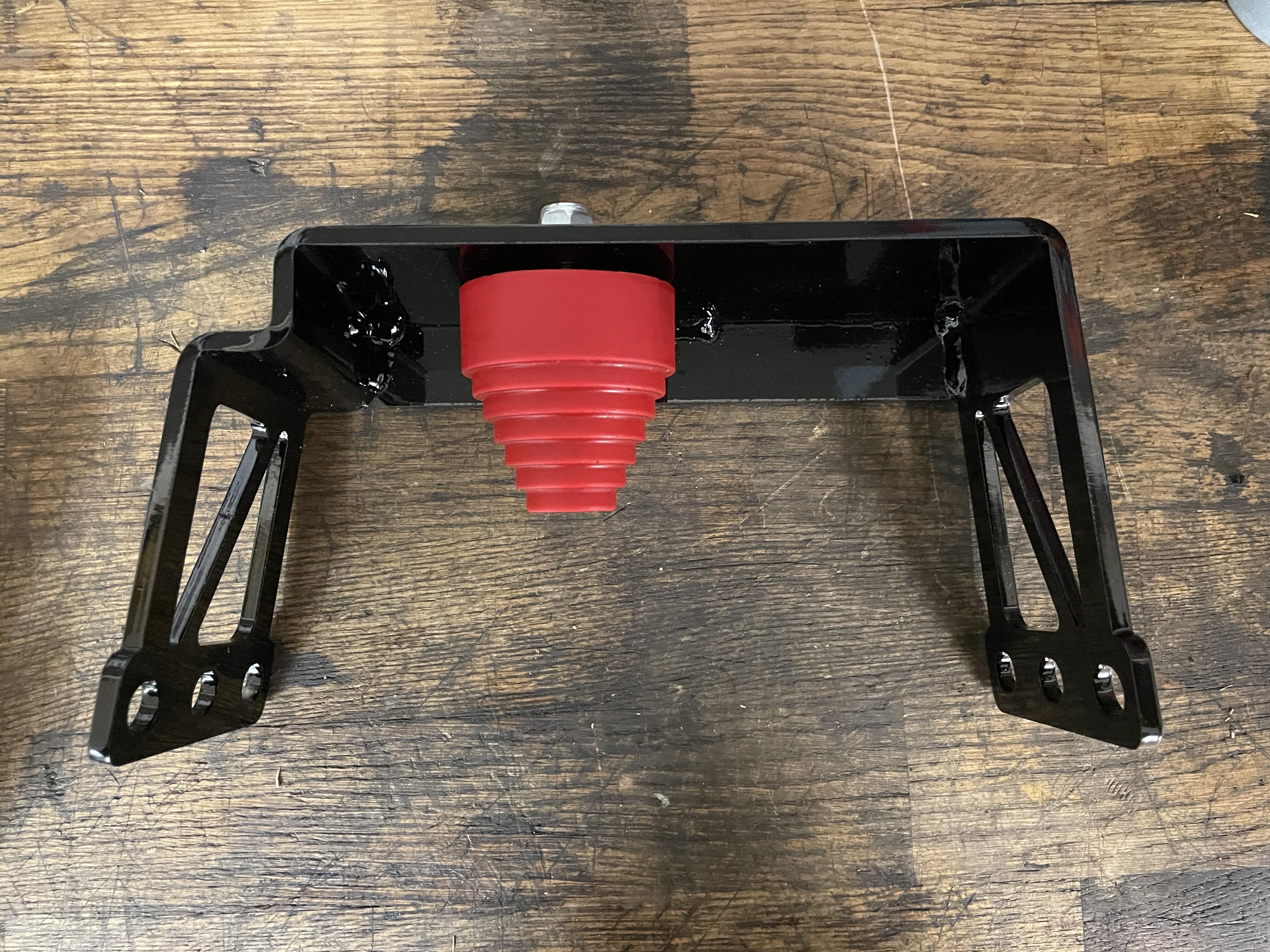
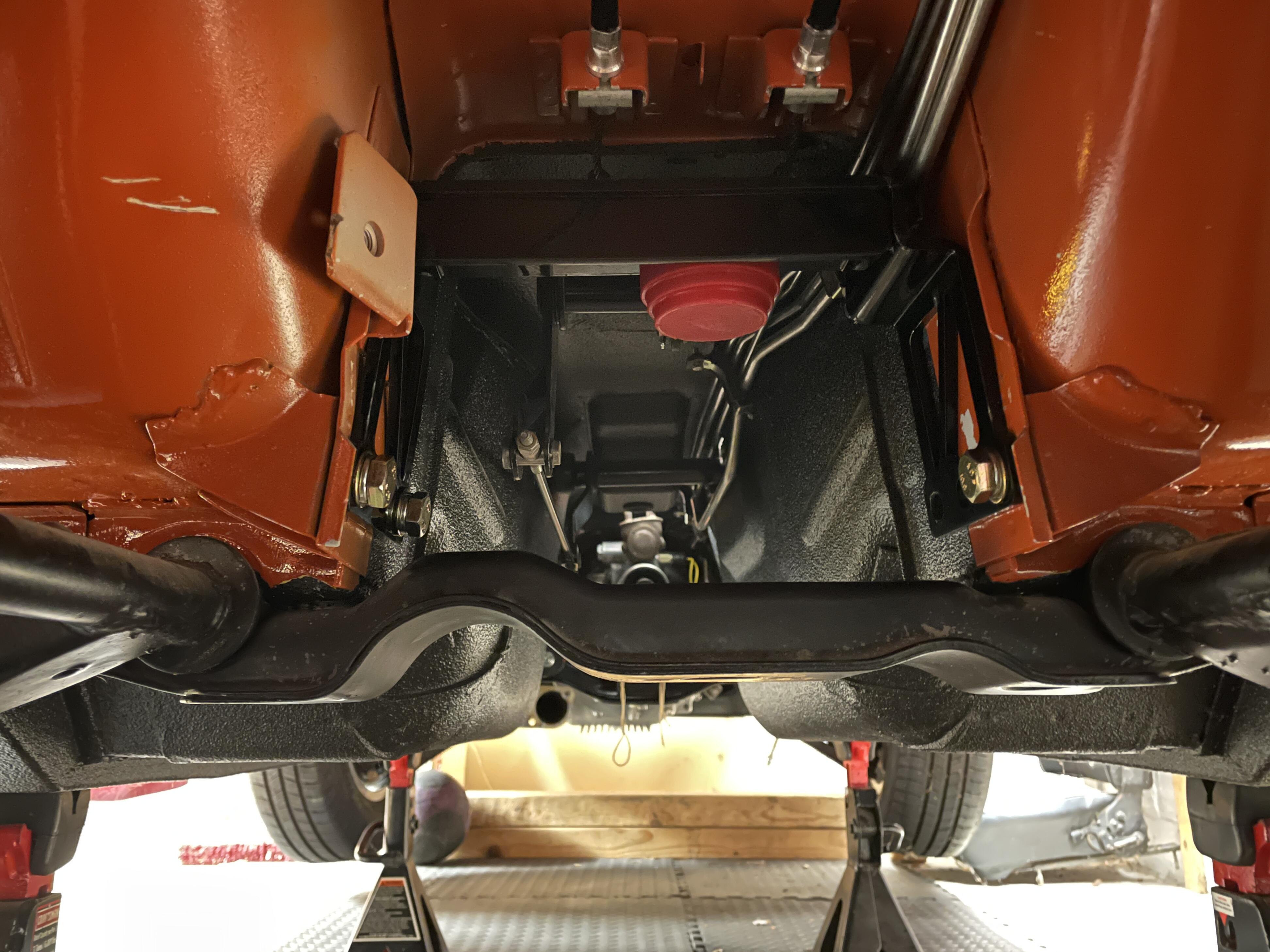
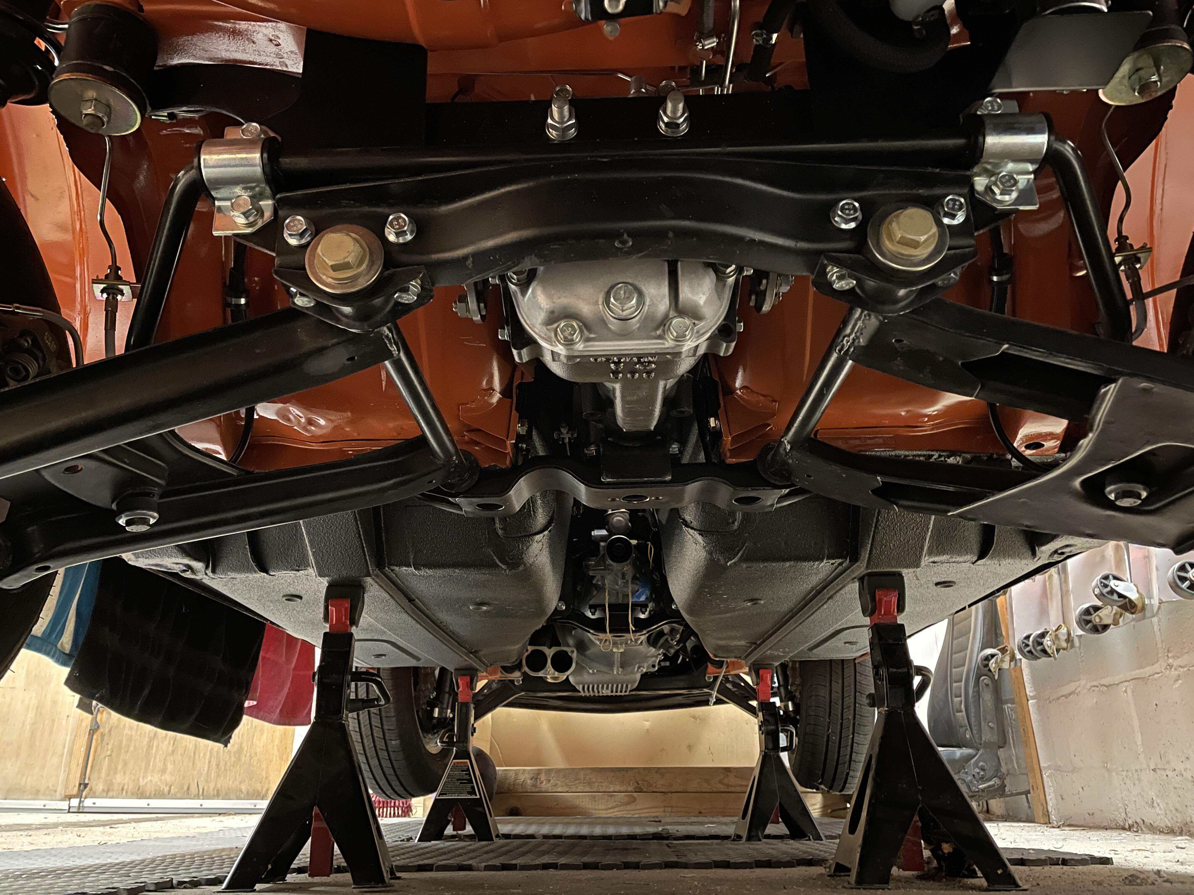
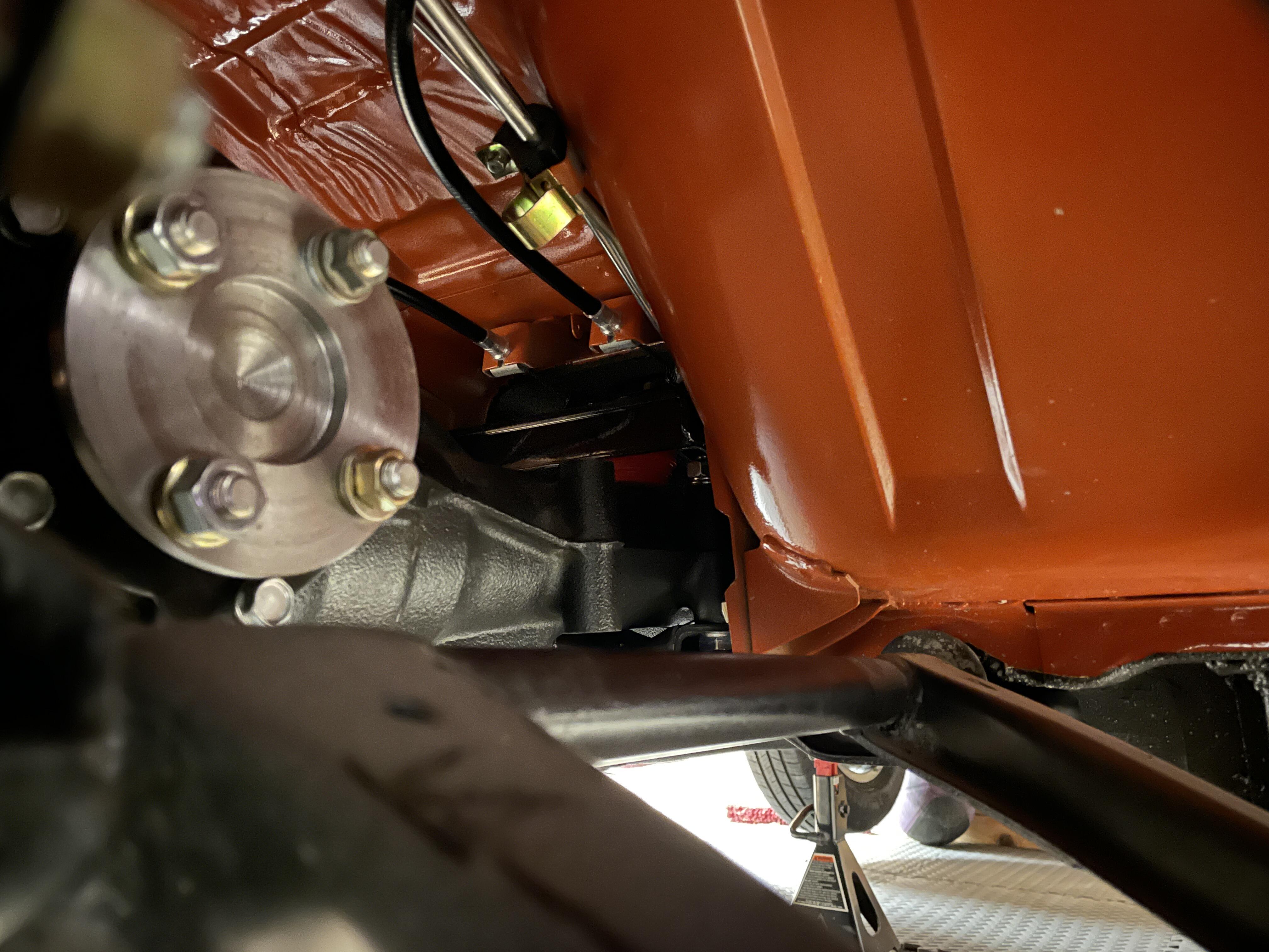
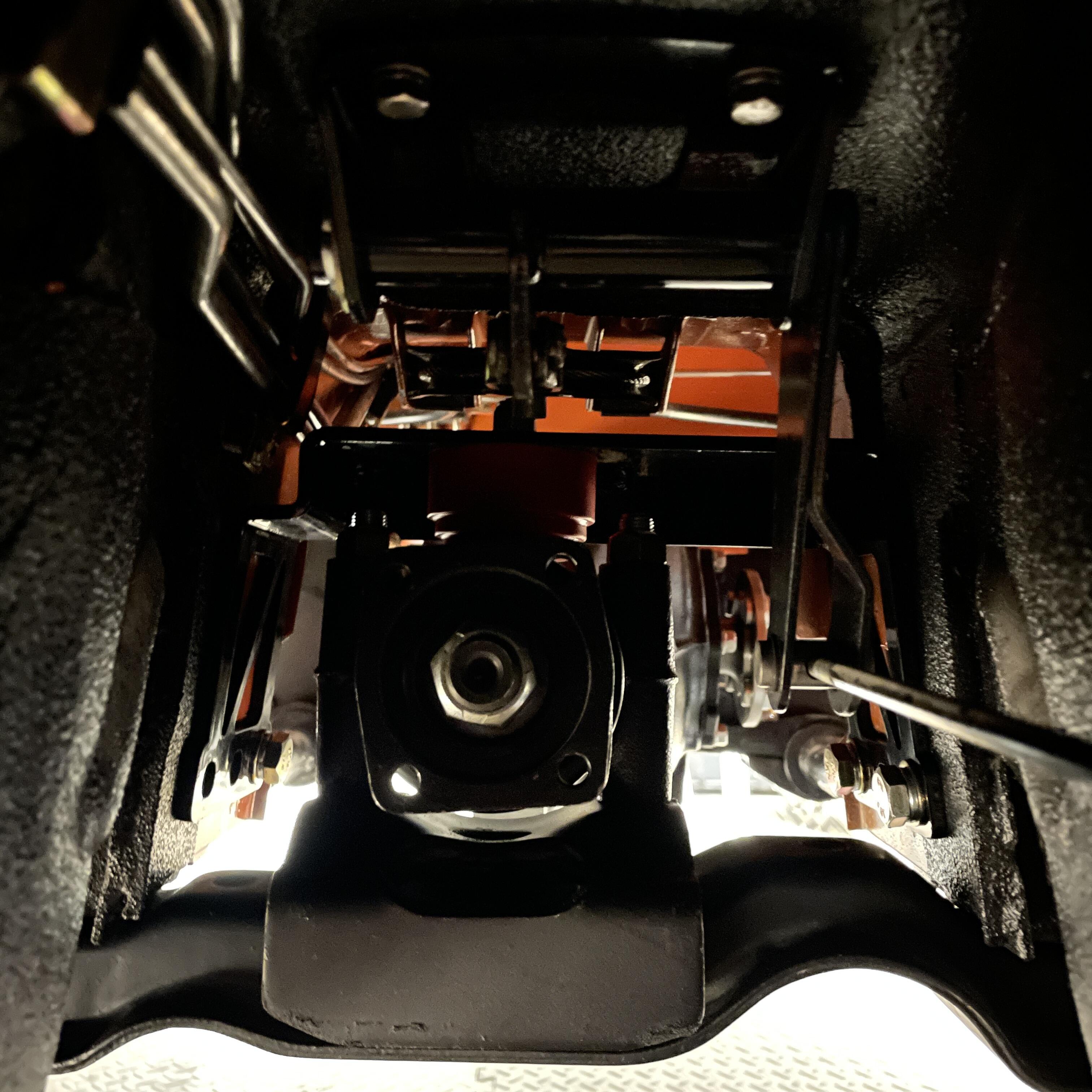
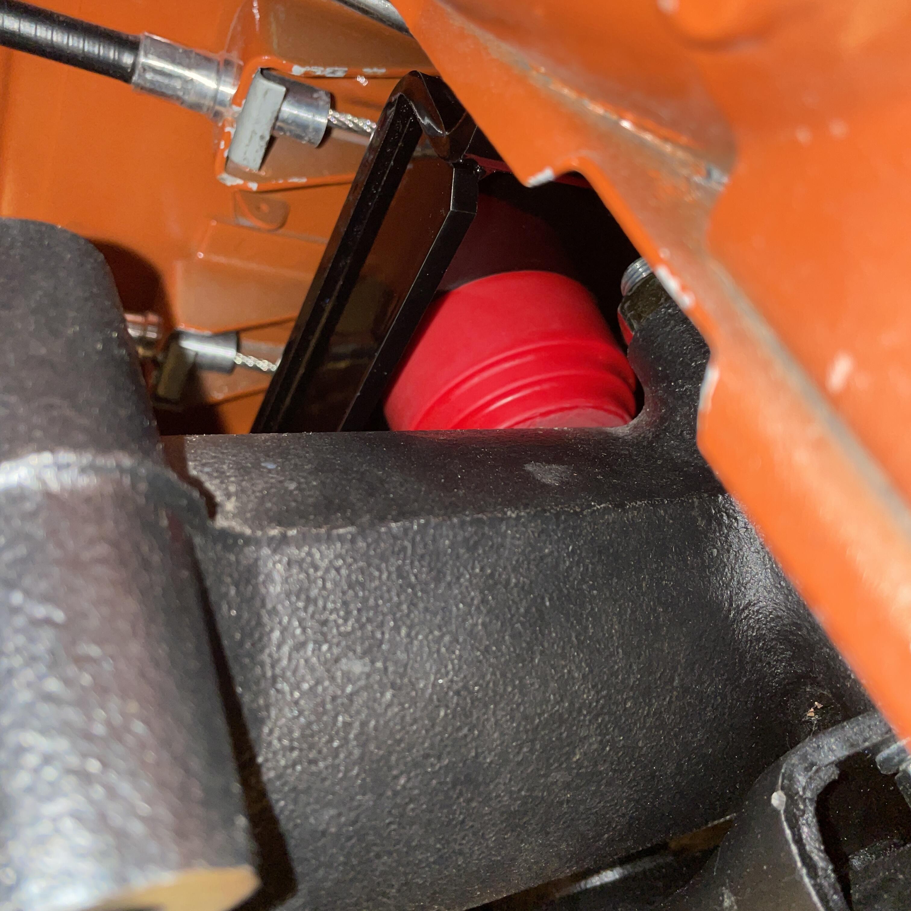
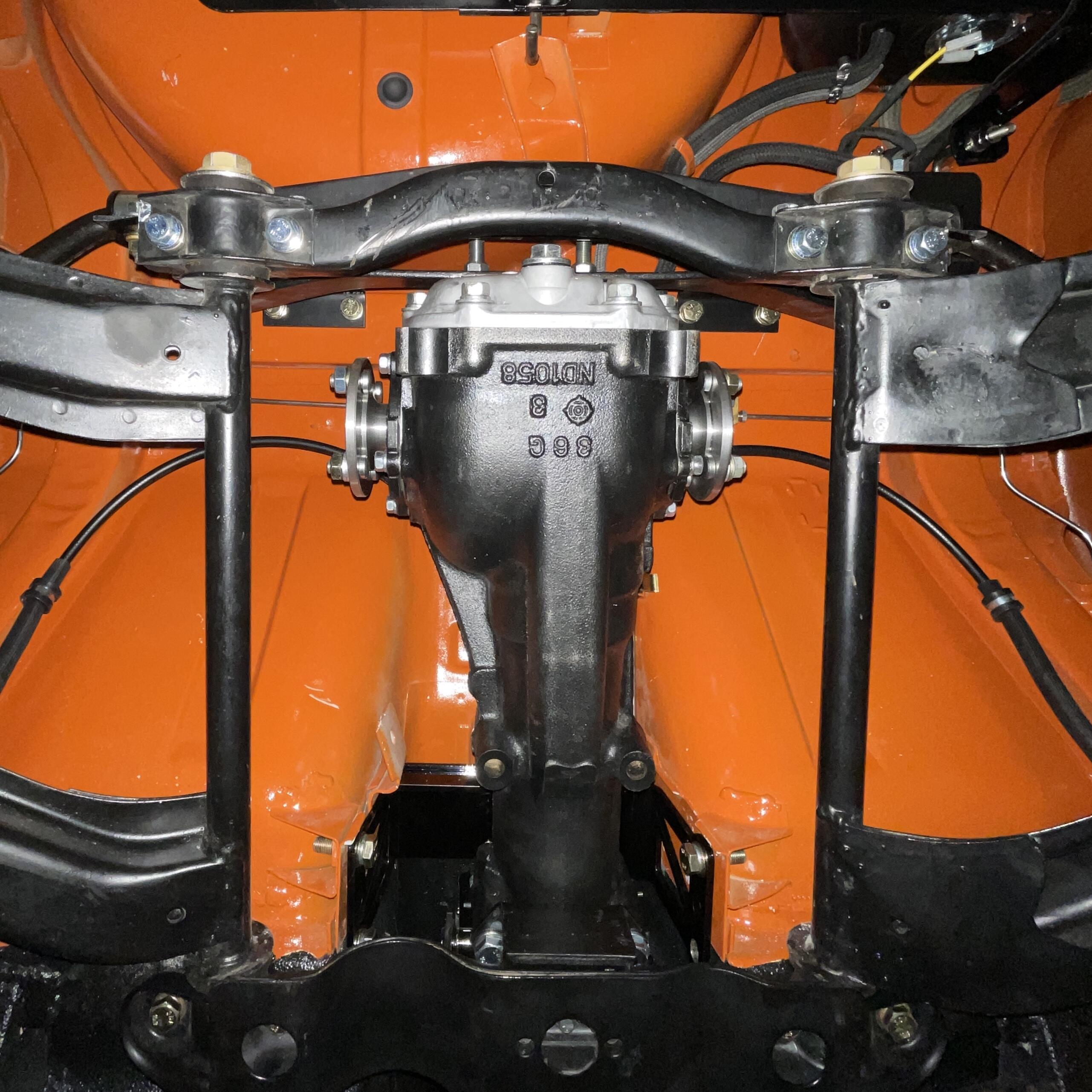
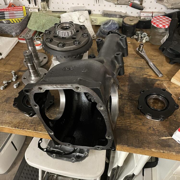
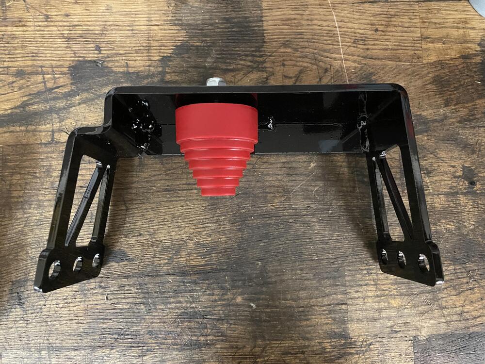
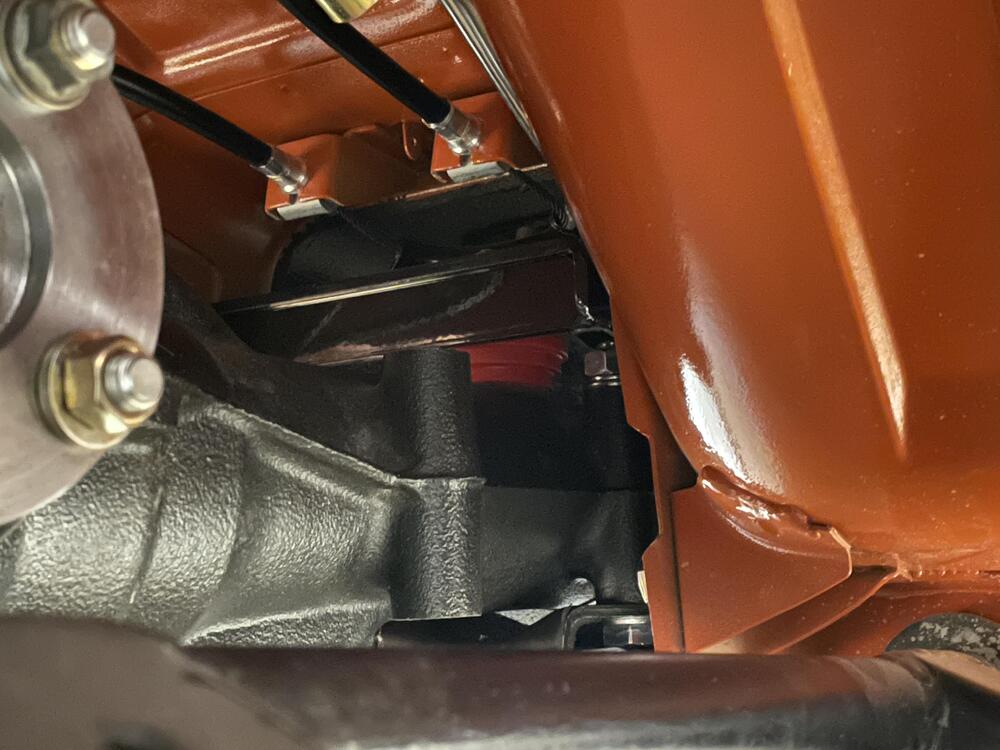
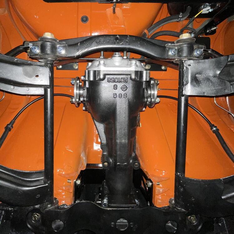
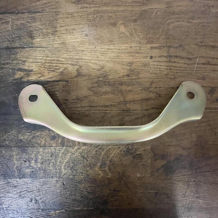
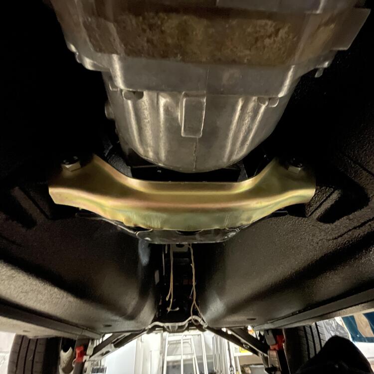
Alright, the suspect carrier is in a vat of oil and the new one is in. This one has fewer miles on it anyway, so I’m looking at this as a glass half full situation. Once I had everything ready to go back in I put fresh bearings on the new carrier and new seals in the case, which is what caused this most recent delay. 🙄 Figuring out how to torque the ring gear bolts without putting it in a vice was fun. The key ended up being an oil filter wrench with a reinforced rubber strap. Two people can do it, three would be better. They need 78 foot pounds on the Subaru diff (probably the same on all “K” r180s). They are only 50 to 58 on the Datsun (probably because they have lock washers). Luckily I had the right mix of shims to get the backlash within tolerances (0.1mm to 0.2mm). Major obstacle out of the way! Edit: I forgot to mention the Ron Tyler style differential arrestor. Not much to say about it other than I was surprised how much of the bushing had to be removed to get the r180 to fit. I only had two notches to go before it was all the way to the hilt. I’ve seen these where there was a gap leftover but they must be using a different bushing. This one is pretty compressed. This isn’t going anywhere. *** So now the differential is in. My 240z now has a limited slip… sort of. It’s a Torsen, so not a true LSD, but I’m thinking this is the most drivable option given it behaves like an LSD under power and like an open when you let off (open into the turn and closed out of the turn). *** This was perhaps unnecessary, but Nissan added this transmission mount shield when they designed the 280ZX/S130, so it is probably not a bad idea. It’s not like it weighs a ton.


-

1973 240z Custom Wiring From Scratch
Matthew Abate replied to Matthew Abate's topic in Build Threads
Haha! Thanks. Note that there are some errors in those older spread sheets. Make sure you triple check everything as you go! I’ll post the latest info when I can. Dashboard wiring should start next month. -
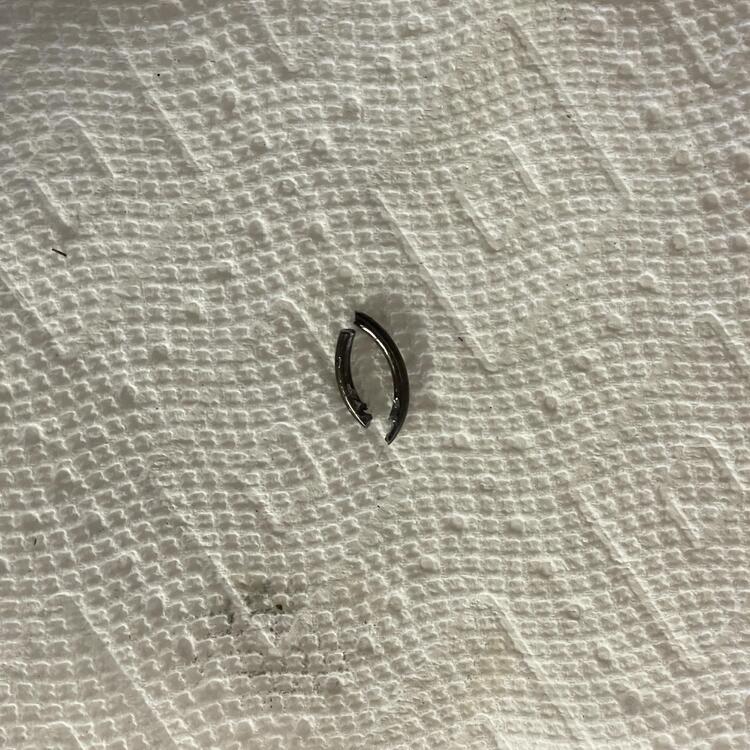
Culprit identified. This must have happened when the axles went in. Clearly the “5-Pound Hammer” method promoted on the Subaru forums is ill advised. I’m going to have to split the carrier open to really make sure there are no more bits in there. This is what I get for not using a press.
-
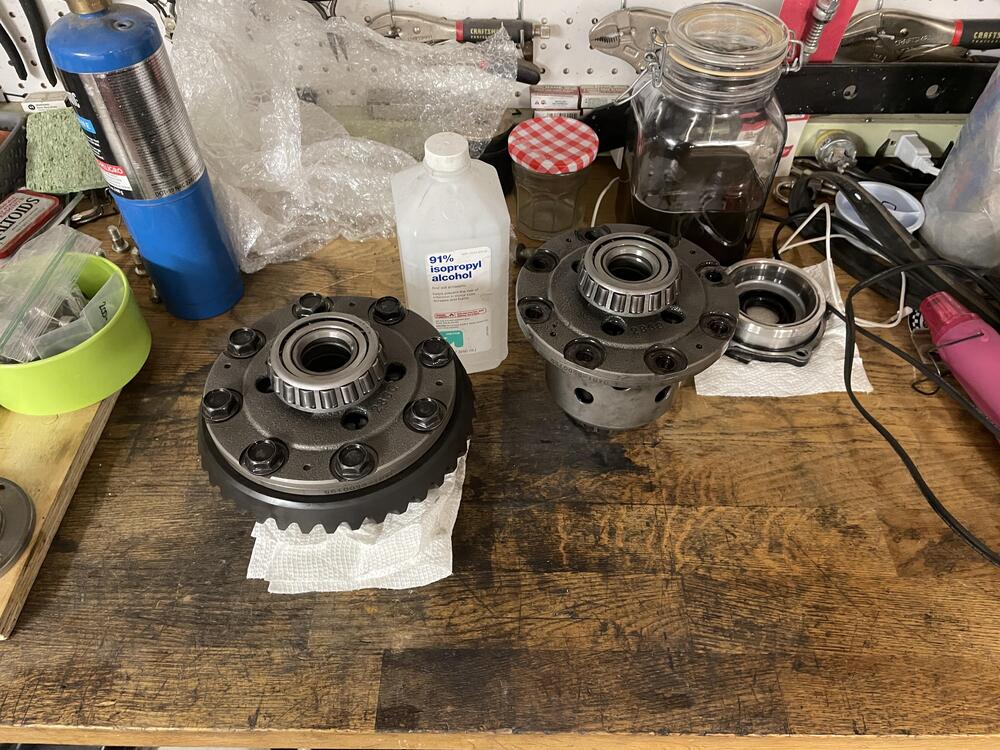
Well, I’m doing this now. Once I had the stub axles in the diff felt really chunky and would occasionally lock up as I twisted them back and forth. I flushed it and couldn’t find any metal, but things never really improved. Luckily (I guess) I have a duplicate Torsen carrier. It isn’t exhibiting the same issues so I’m swapping it in. Just waiting for some bits so I can finish this up.
-
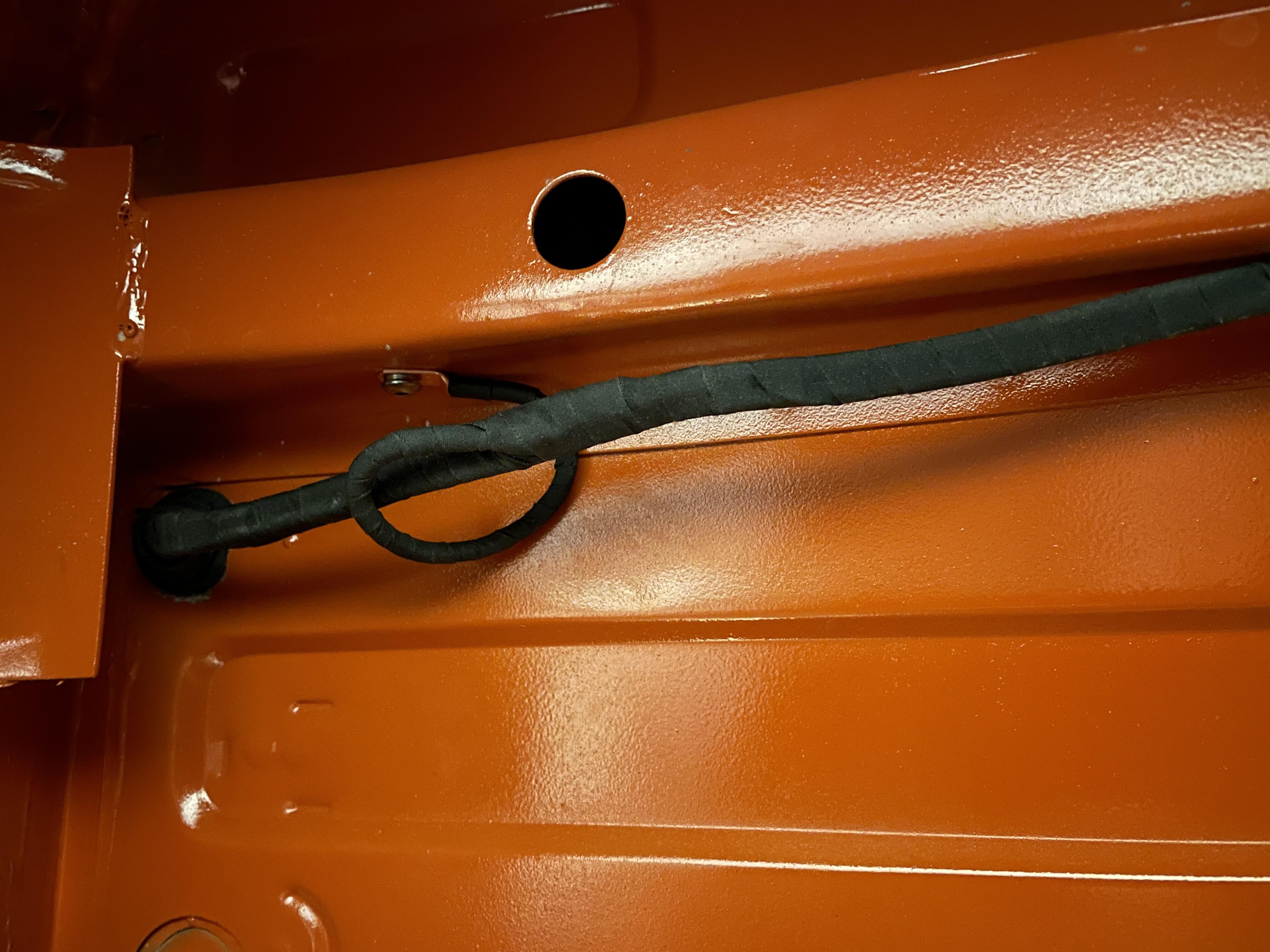
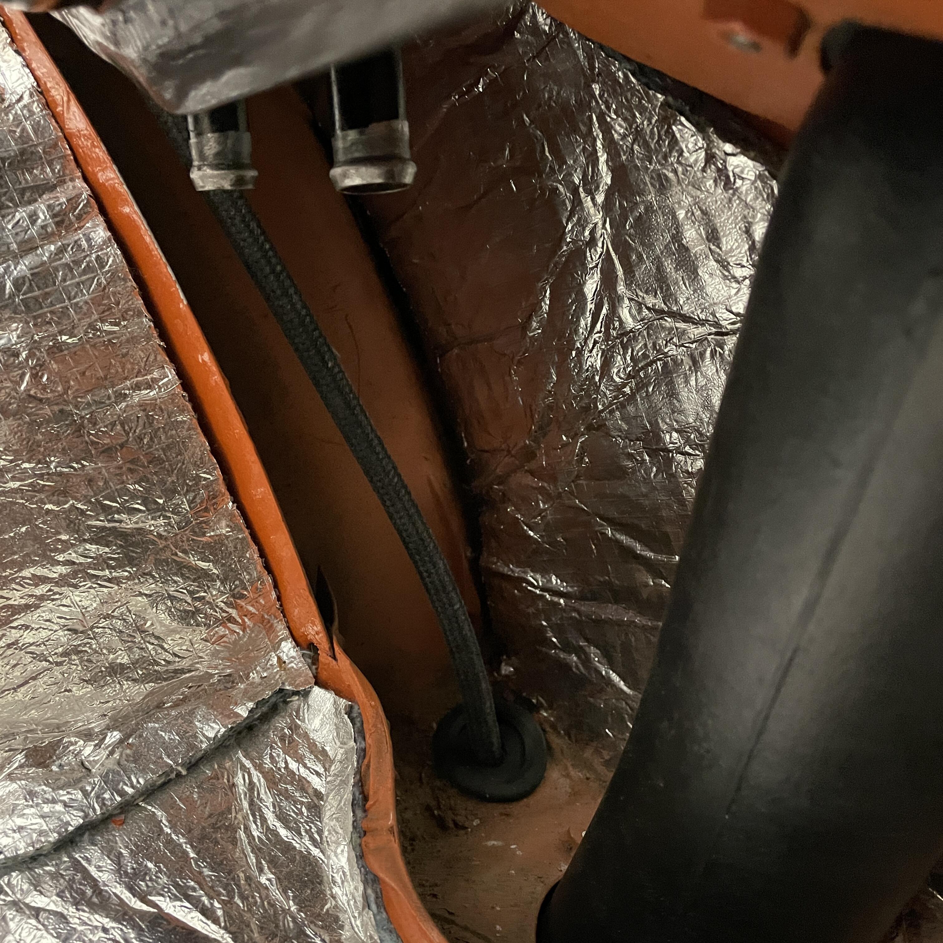
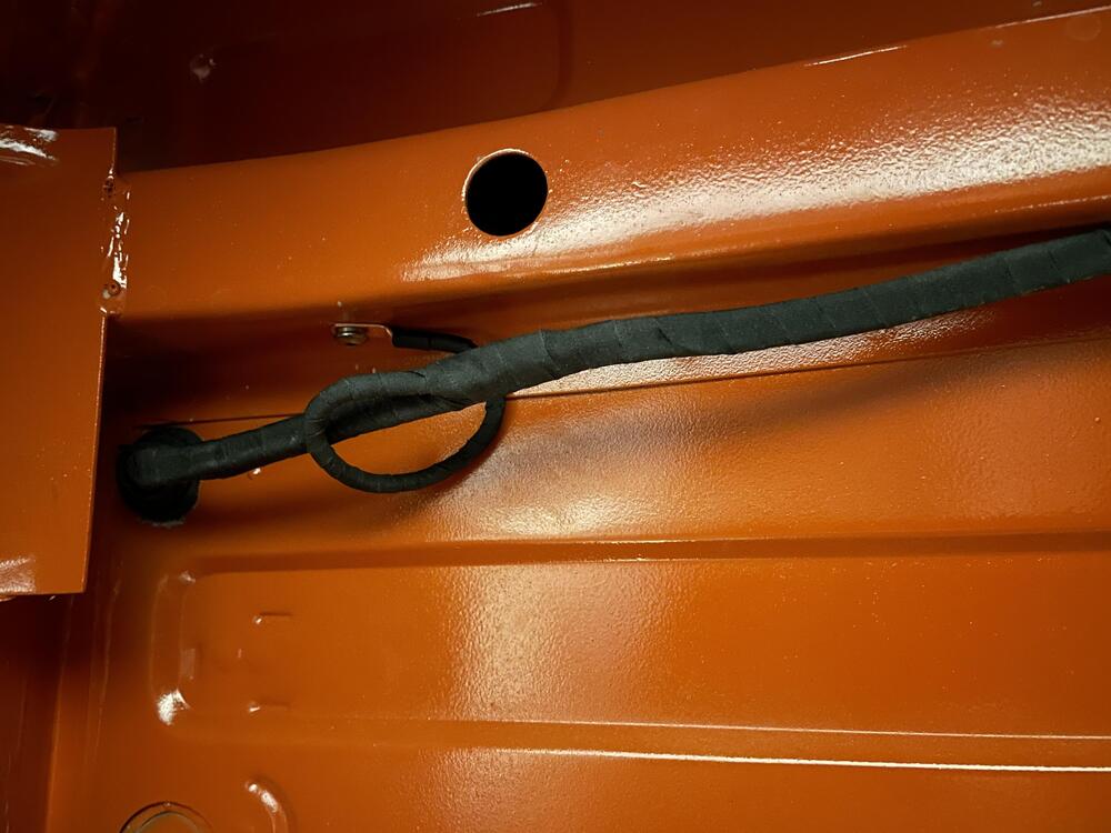
Working backwards, the insulation kit is from Collectors Auto Supply. I bought a box of Dynamat to augment the kit because I didn’t feel that it was quite enough, particularly the roof, which you have to completely cover so you don’t see lumps through the headliner. No, I didn’t presssure test the vacuum tank. I did a thoughough visual inspection, which, granted, may not be adequate, but I’m trying to get the engine stated asap, so I’ll find out if it’s leaking long before the interior panels go in. I decided to keep mine in the car after reading that the system allows vapors to expand and condense in a way that maintains a certain amount of pressure in the system so that two things happen: 1. The fuel stays in the front of the car when the car is nose up on an incline so there is no delay in it arriving at the carburetors when starting, and 2. You don’t get sprayed with gasoline when you open the gas cap, hence the valved cap. The routing is pretty efficient. The only way they could have avoided it is not having a port on the left side of the car (skinny end of the tank). Also, the hoses have to route in a way that the vapor tank lines don’t have a low spot that causes fuel to pool in the hose. You’ll see what I mean when you do yours. Yes, there are a lot of hose diameters. I don’t know if it’s true for the hoses, but I’ve read that the hard lines are designed to keep pressure consistent and correct for the size pumps and carburetors in the car, meaning the return is the smallest. The vapor tank is probably also optimized for flow, so big fat hoses. The hose that is going to give you the most trouble is the hooked one that goes through the frame from the vapor tank to the top of the gas tank. It’s one or two millimeters too small. If you get the same hoses I bought, you’ll need 5mm x 3ft, 7mm x 3ft, 9mm x 10ft, 12mm x 10ft, and 17mm x 10ft. I also bought 3 feet of the 3.5mm just in case I need it later. Yes it’s weird that they sell metric hose SAE lengths.
-
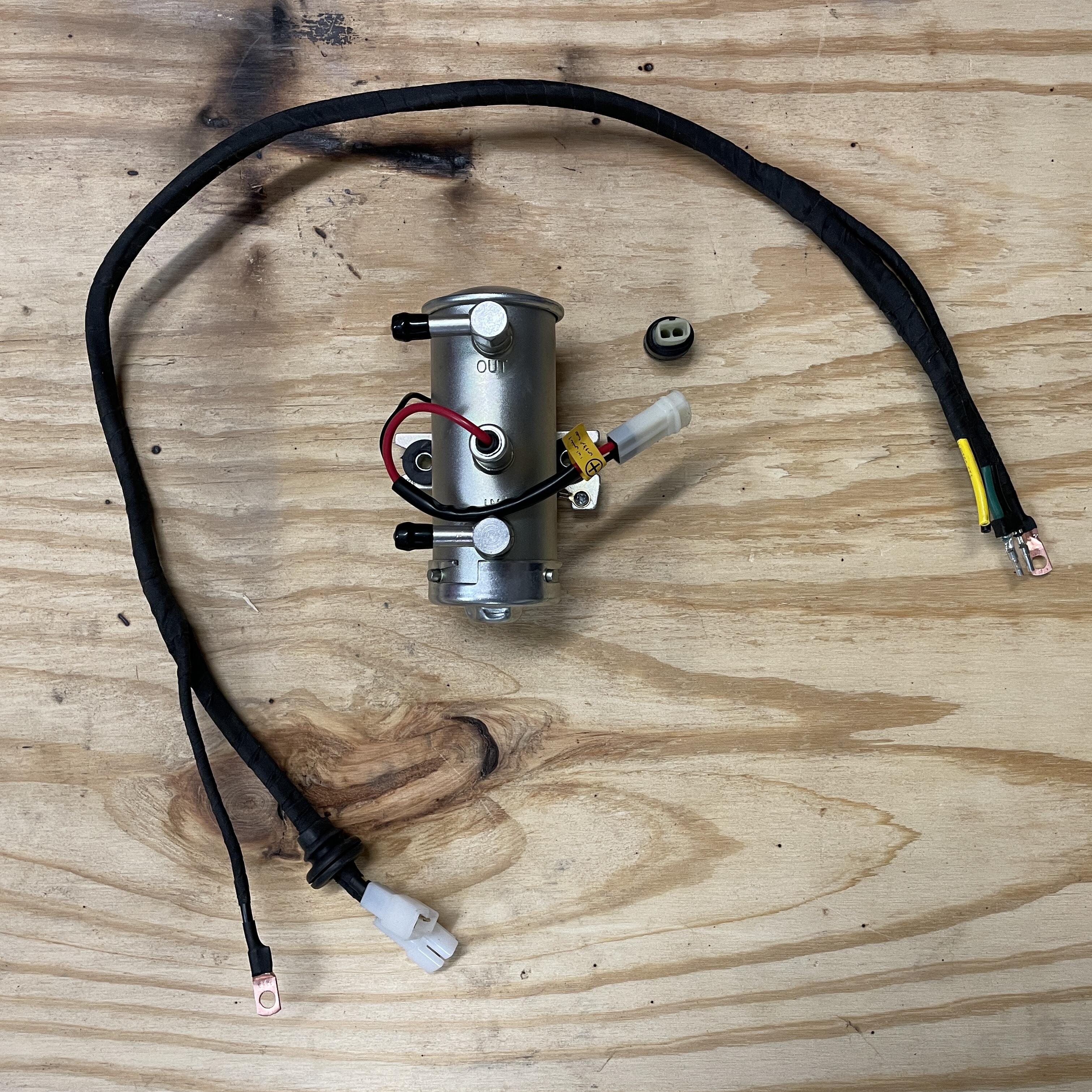
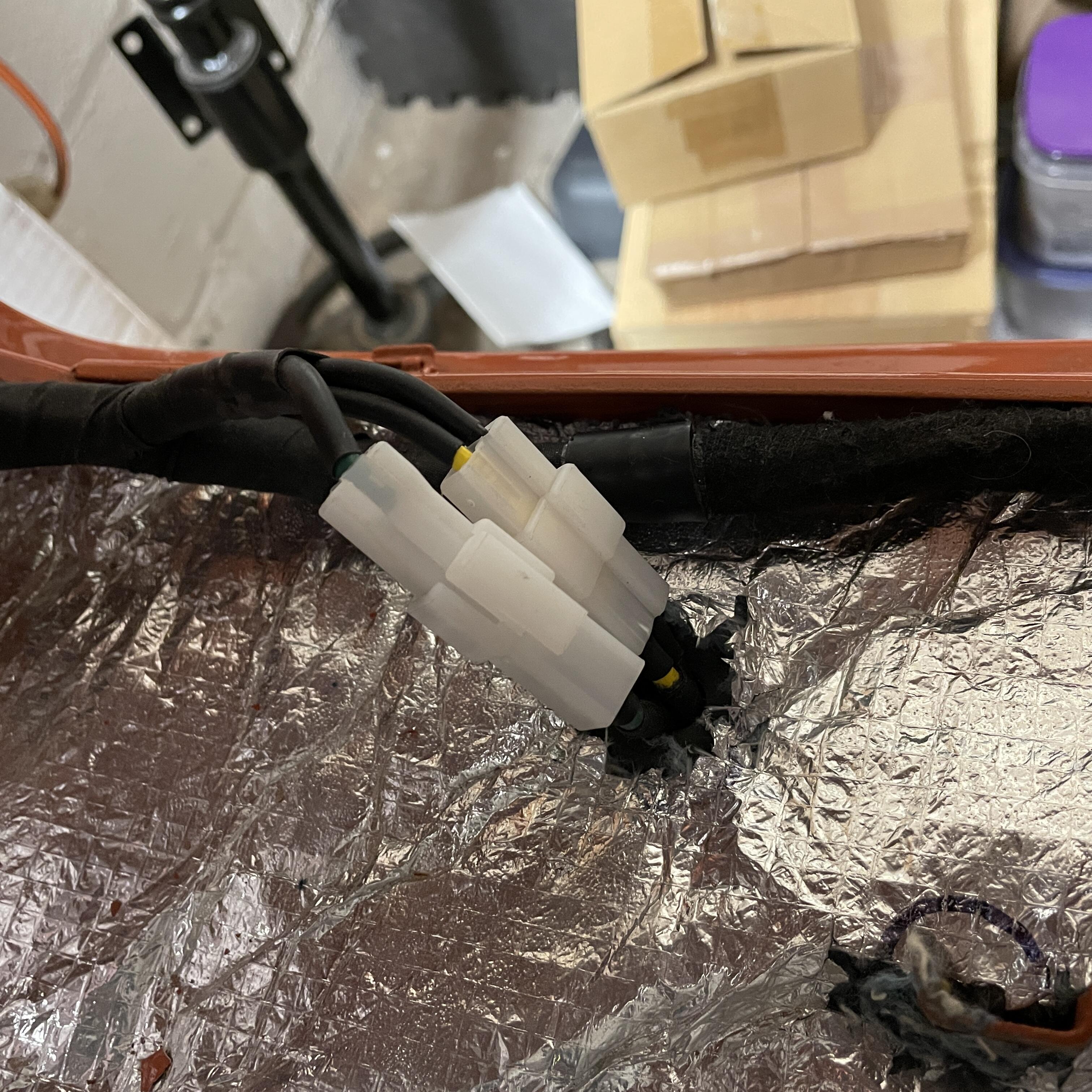
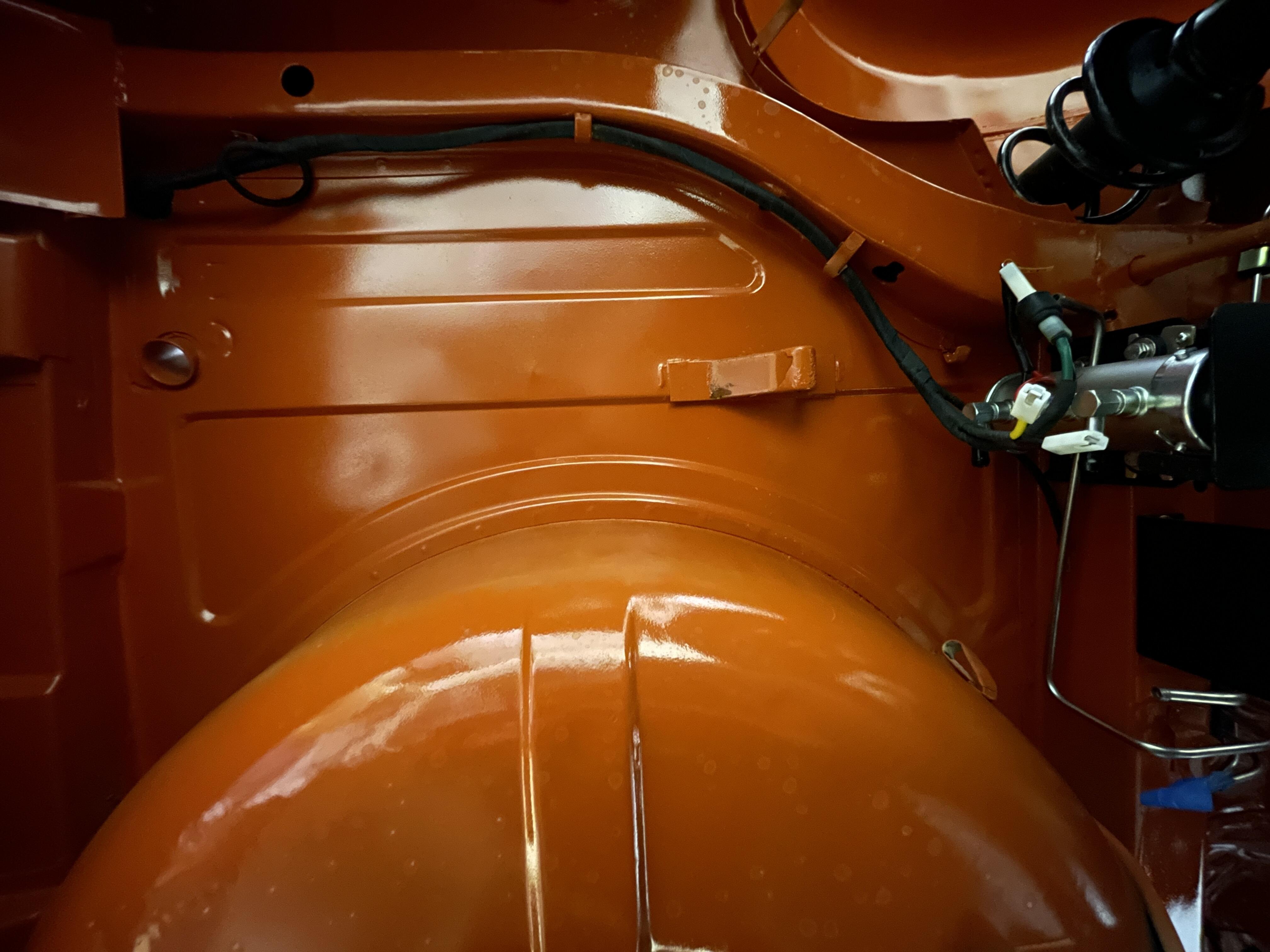
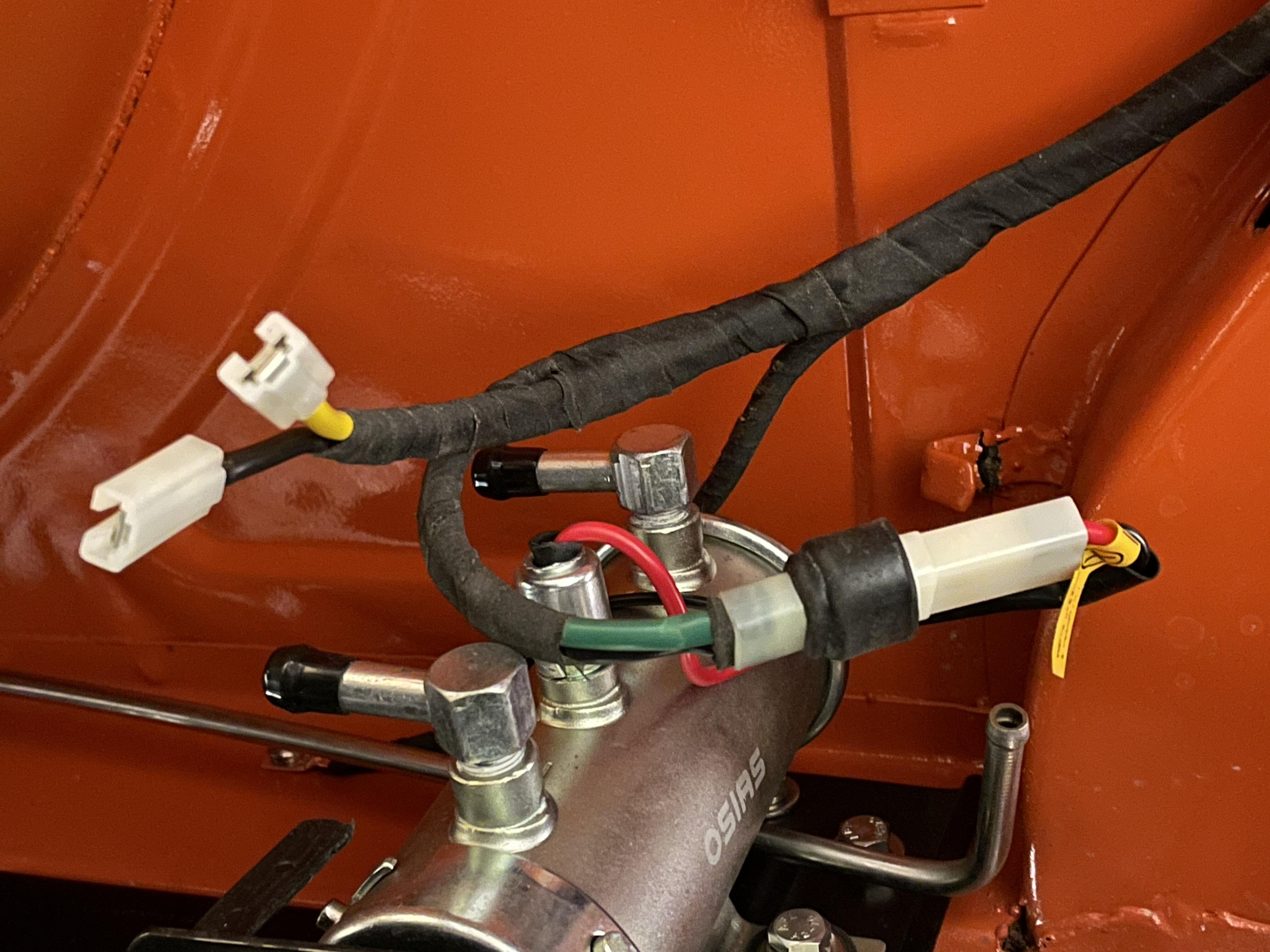
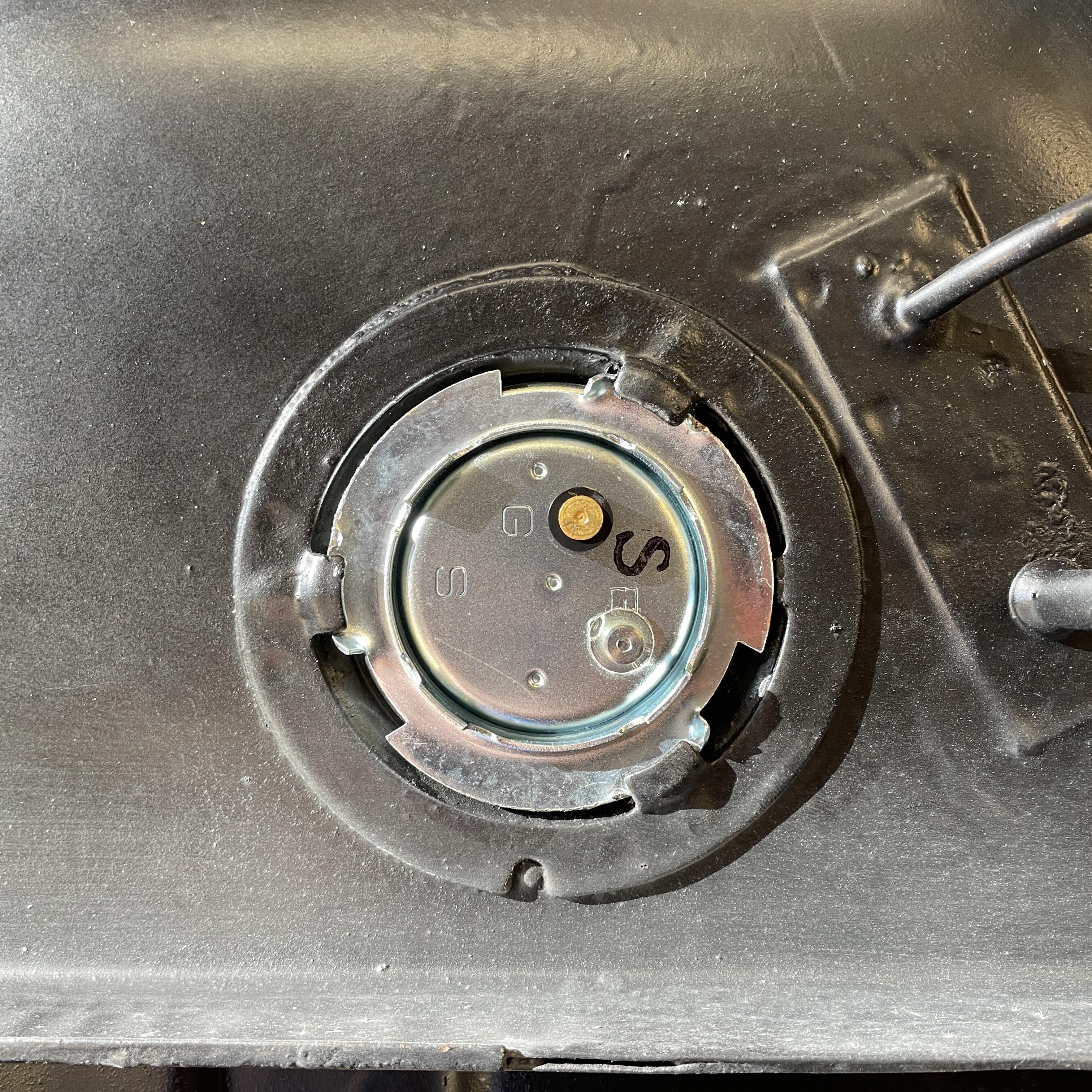
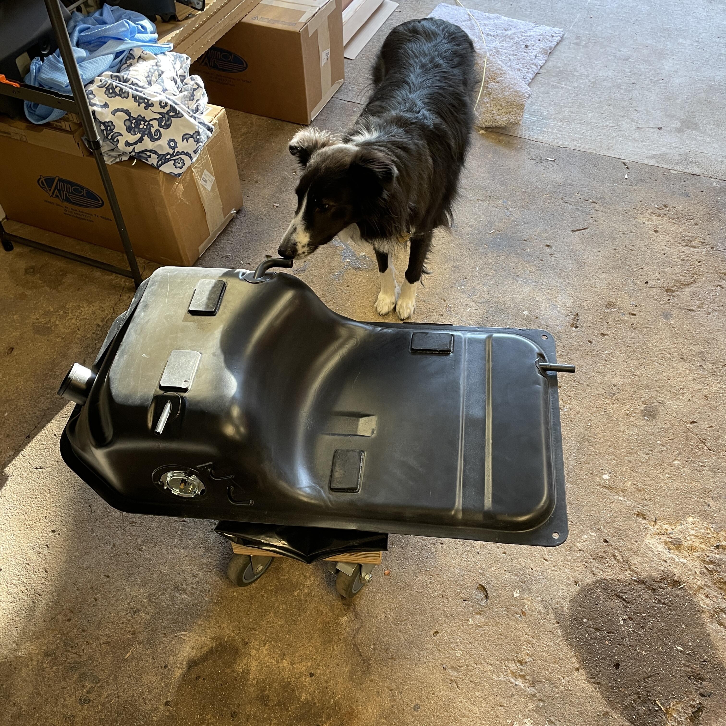
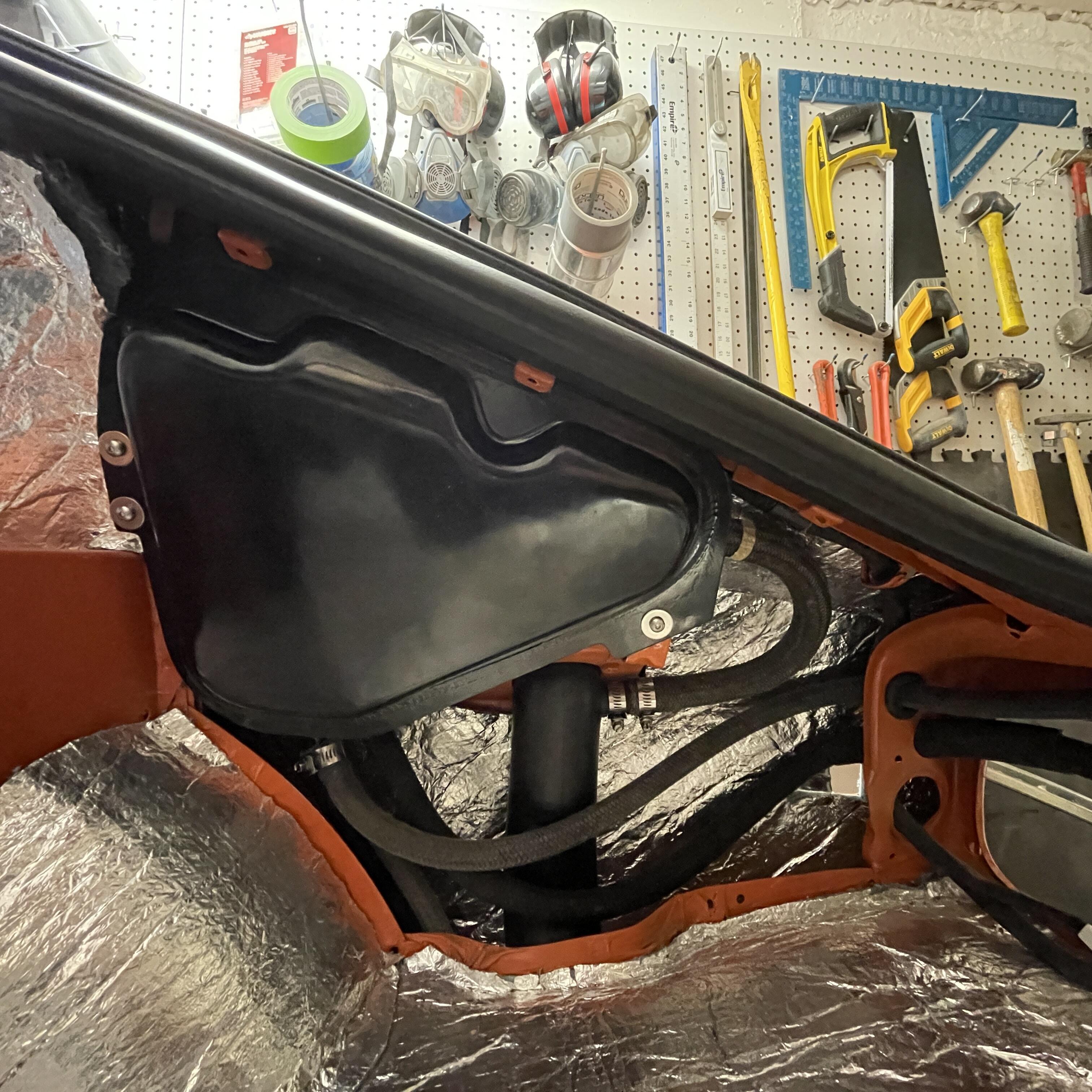
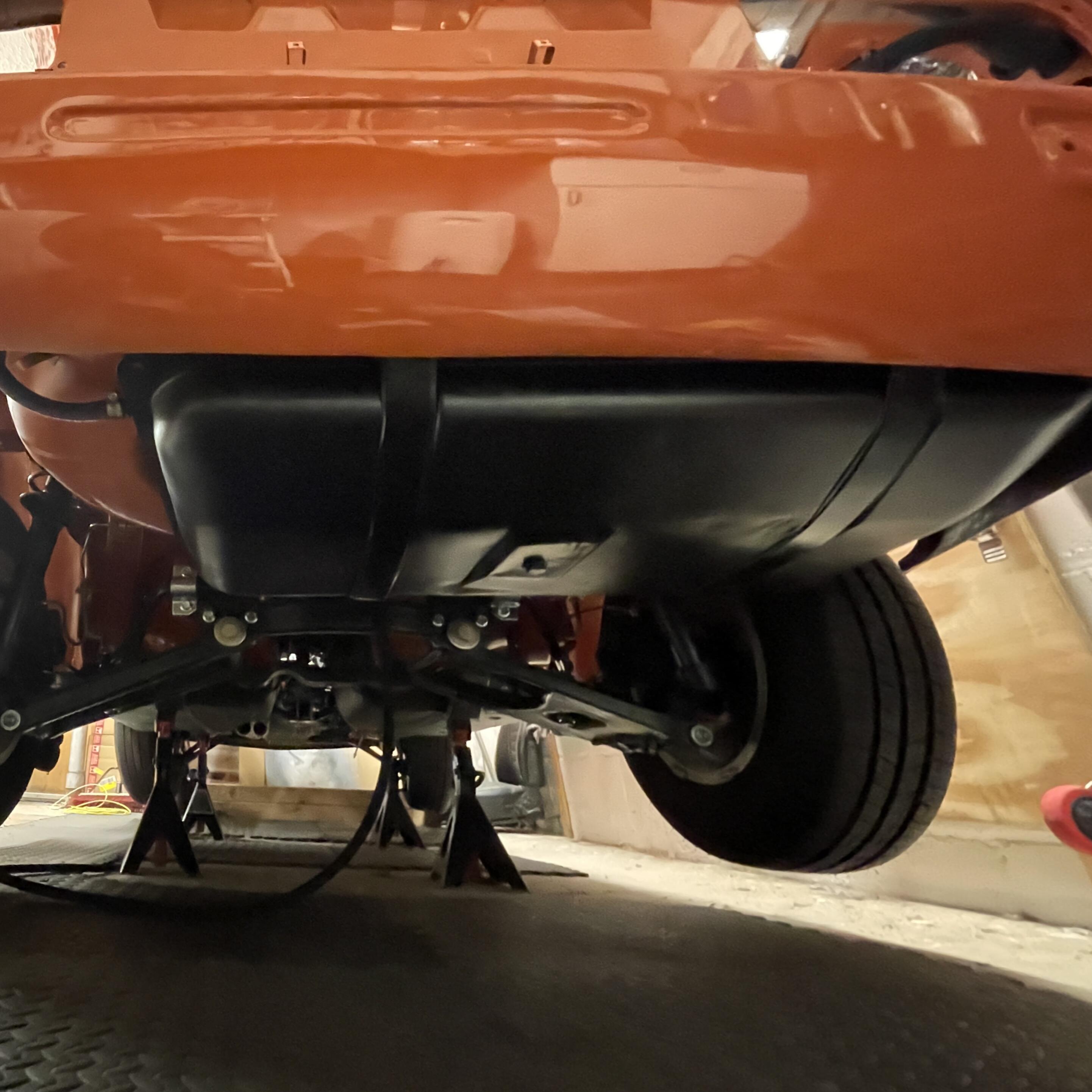
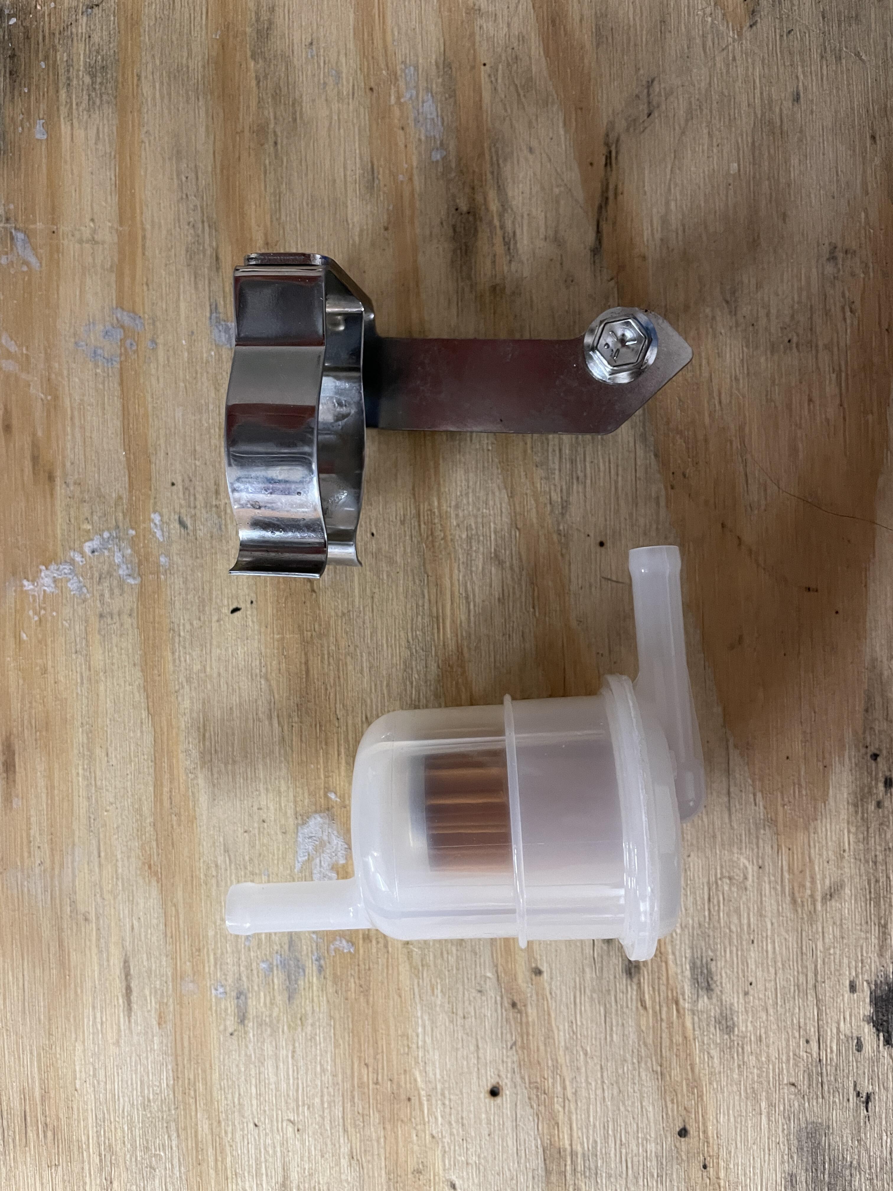
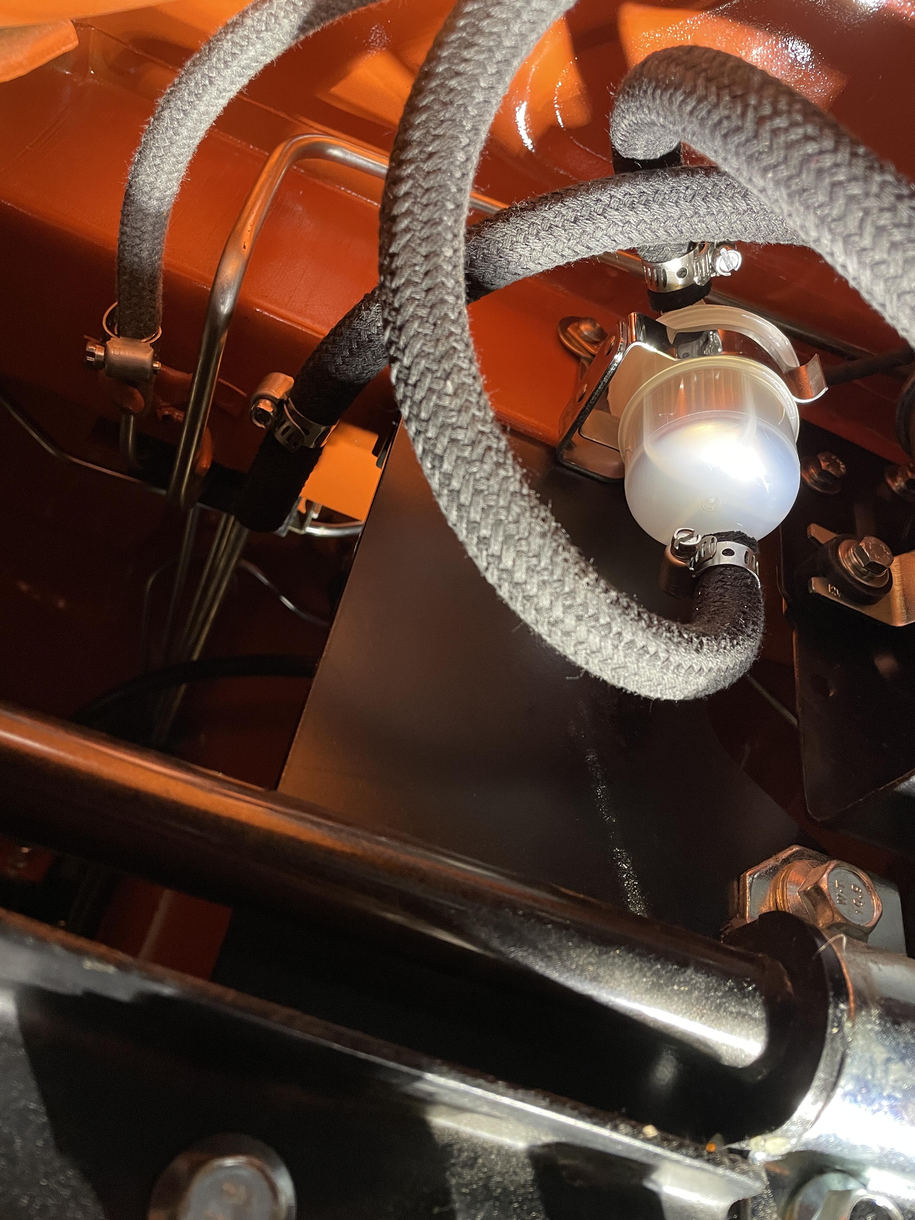
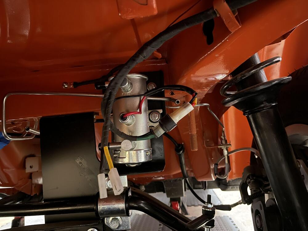
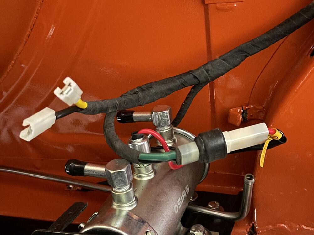
“We got to run on heavy, heavy fuel…” The gas tank is in, the vapor tank is in, all the fuel lines are clamped down, the filler neck and cap are in, the pump and sending unit are wired up, and the system is closed from the hard lines back. I got hung up because I forgot to refurbish the straps, so that knocked a day out while paint dried. I also never found the right filter bracket, so I picked up a shiny new one for a Suzuki outboard motor that holds the OEM Nissan filter perfectly. The only things I’m a little unsure about are the straps being less tight than before because the stainless Z Car Garage hooks don’t tighten as far as the OEM ones, and not having rubber boots on the sending unit wires. The plastic connectors don’t cover the nail terminals as well as I expected so I may need to make them more weather proof. No, I didn’t go with e85+ hoses. I struggled to find the right sizes in lengths shorter than 50 feet and got tired of holding up the project, so old school FTW. I did use modern stainless steel strap clamps, though, because I’ve read they provide a better seal than those OEM Nissan wire clamps. All the braided hoses came from JBugs California Pacific and are metric. The 12mm hose was the only troublesome one because the metal tubes want something more like 13 to 15 mm, but the 5, 7, 9, and 17 were perfect. The vapor tank hose with the shepherd’s hook bend you can still buy is 12mm also, so I guess we just have to struggle with that. So yeah, I can technically put gas in the car now. ⛽️


-
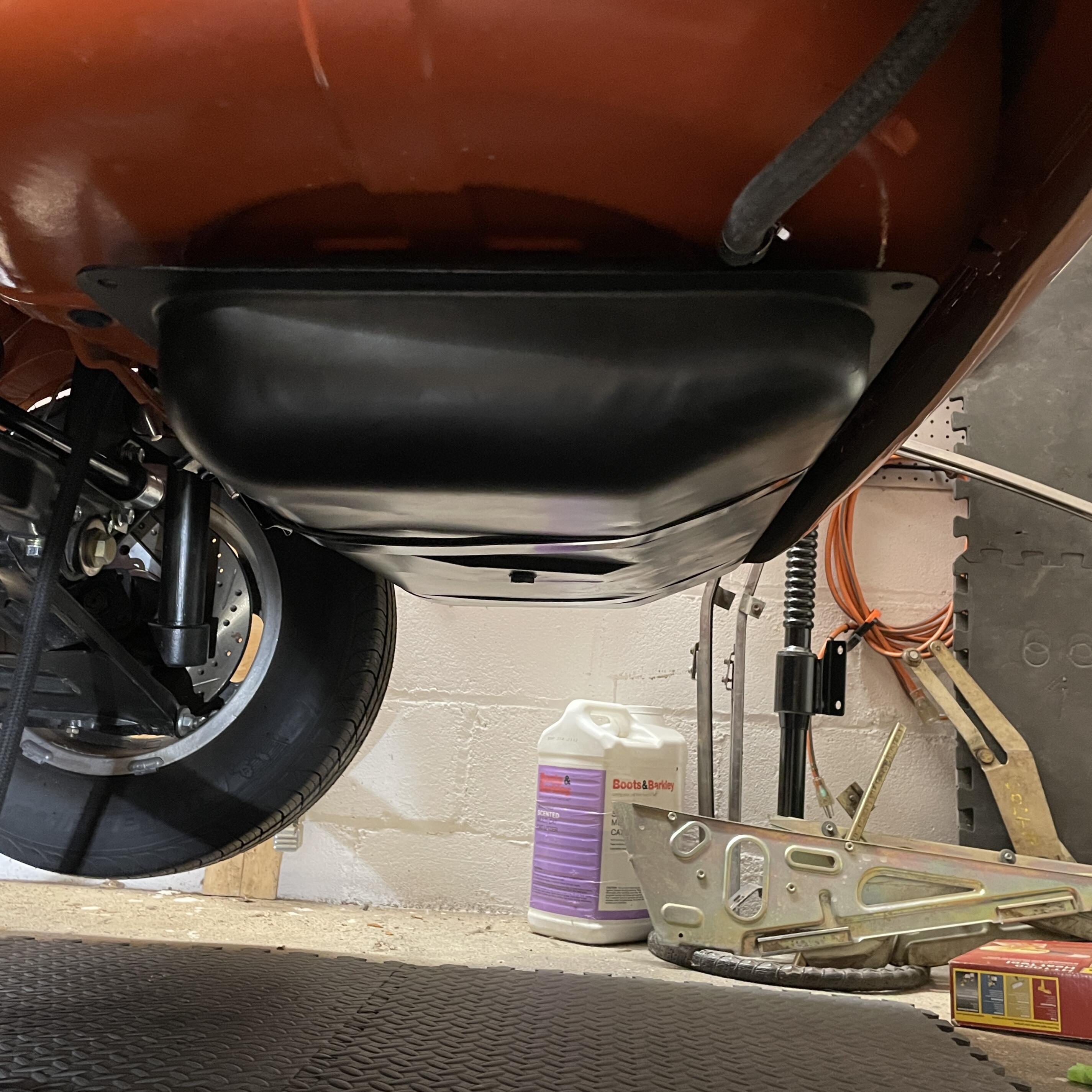
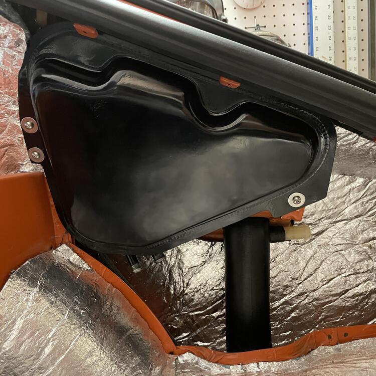
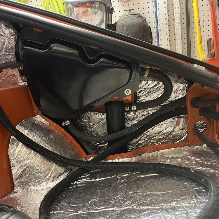
The pump bracket is different here than what’s in my ‘73. This one has the side shield that guards everything from road debris coming off the right rear wheel. It also looks like it comes down a lot further (making space for a filter). It’s possible mine has either the wrong pump bracket or the wrong gas tank, but I’d like to figure out a provision for a filter here if I can. I’m a little surprised that the filter bracket in that photo is a press in clip rather than one that tightens with a screw.
-
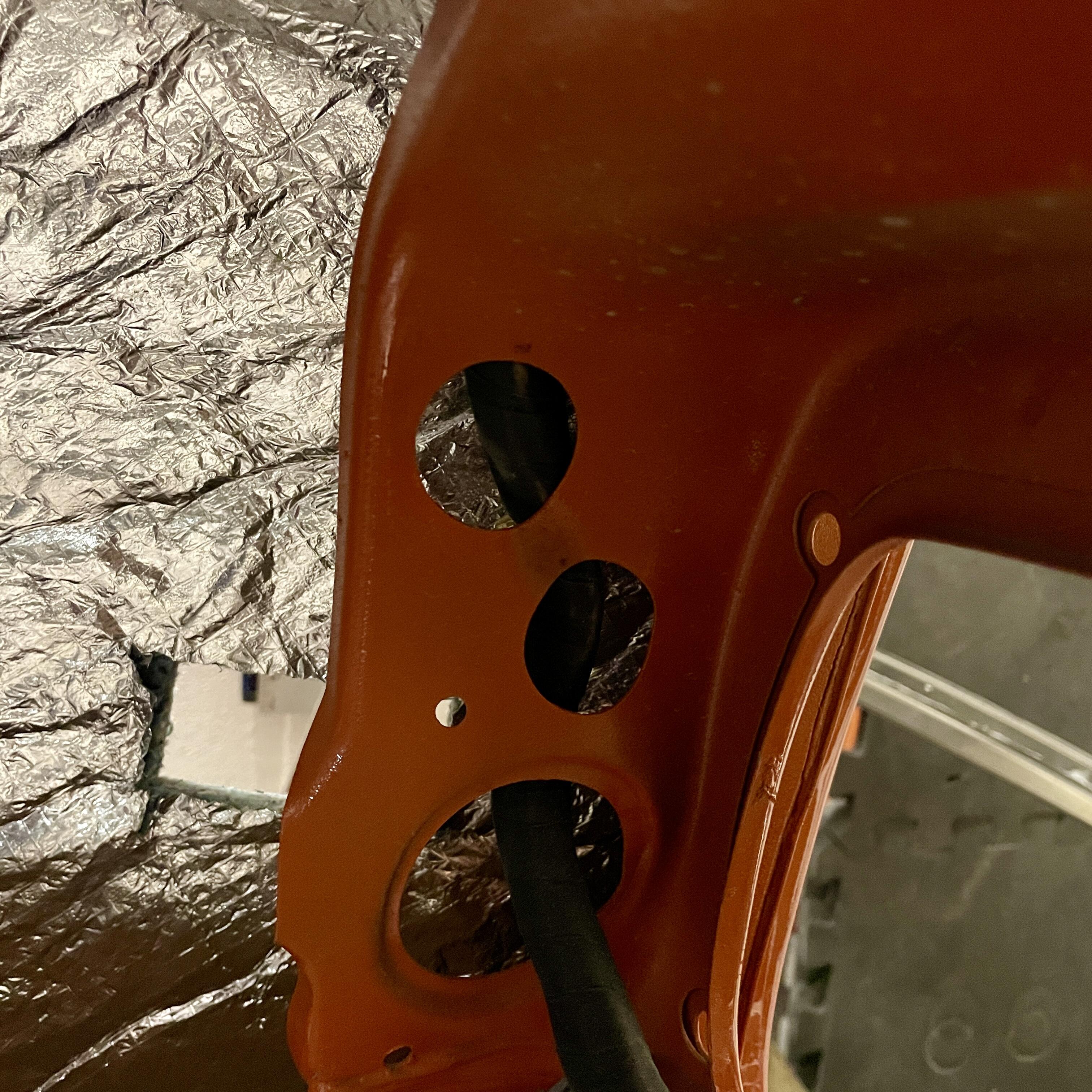
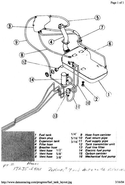
I found that diagram on a thread about refurbing gas tanks with por-15. I thought I saw it somewhere else where @Captain Obvious had commented but can’t find it now. Anyway, this is the setup my car has. I have accounted for everything except the filter bracket and the routing of hoses 8 and 9 through the body (I’ve only found one grommet hole) and that’s keeping me from finishing the tank installation.
-
Can anyone show me a photo of the REAR 240z fuel filter bracket? I can only seem to find the ones for the 280z or the front one for 240Zs and I don’t think I have one. It would secure #13 in the diagram below:
-
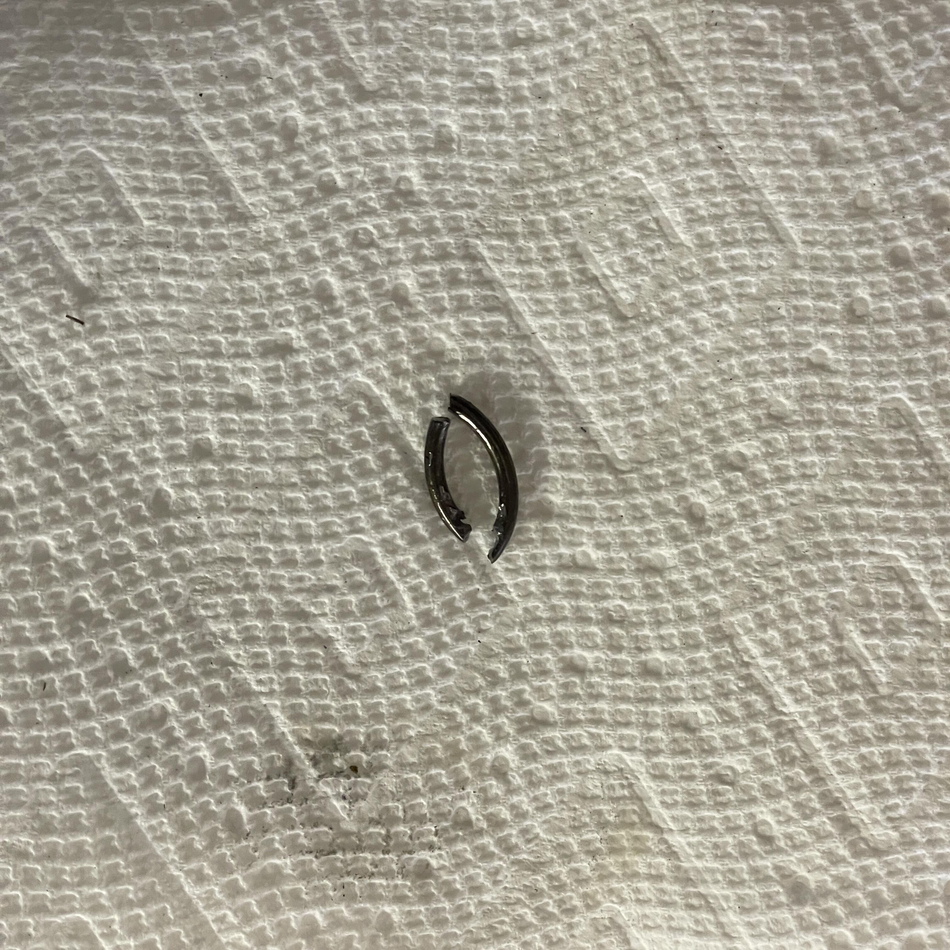
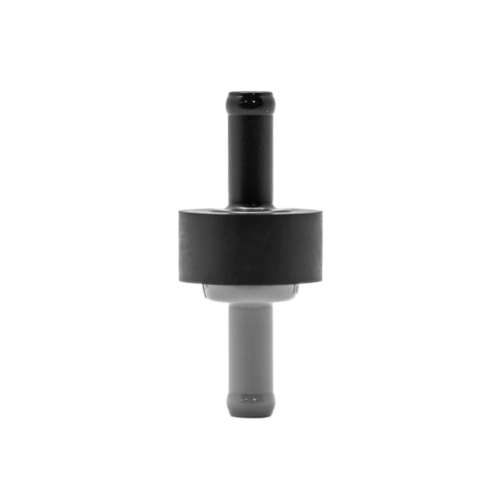
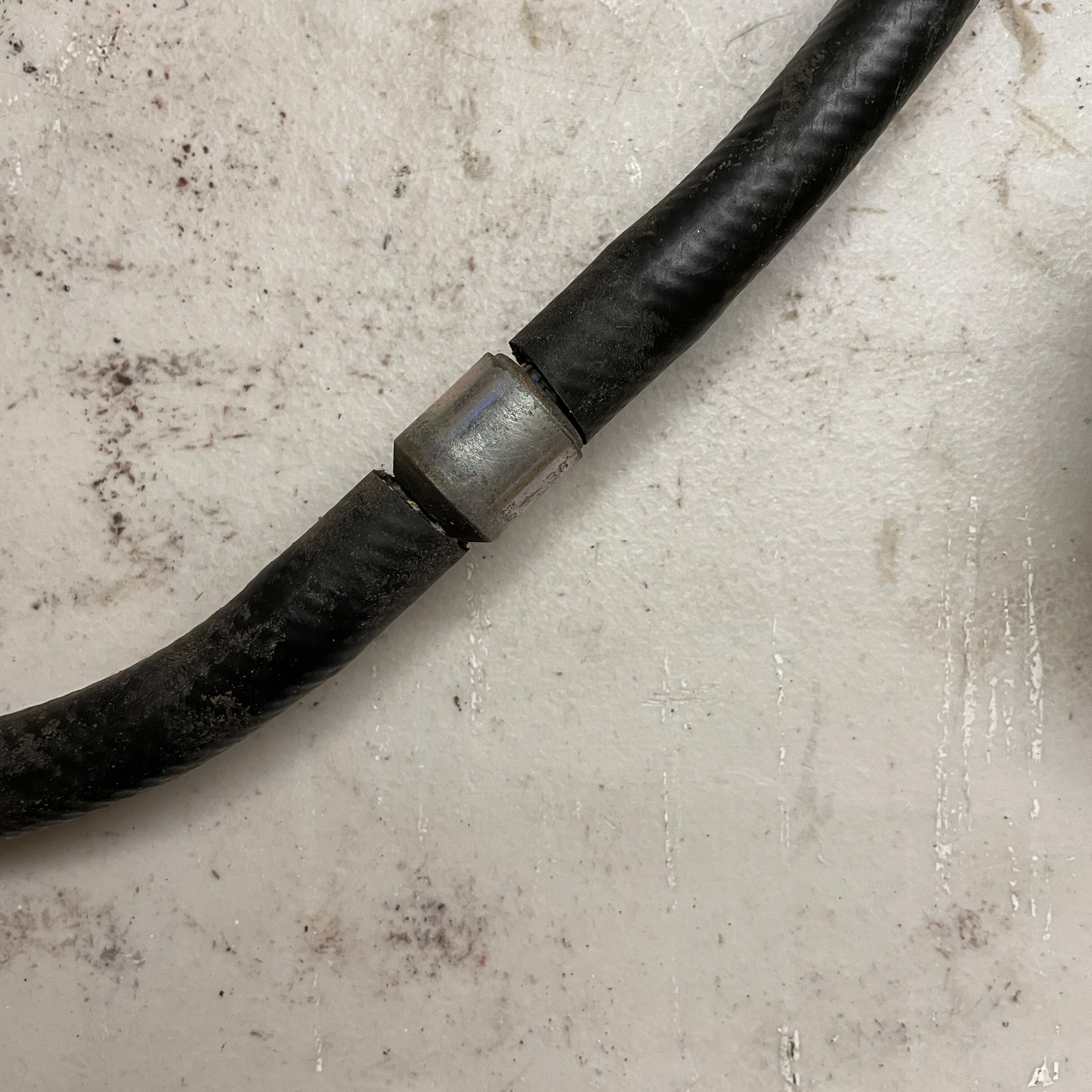
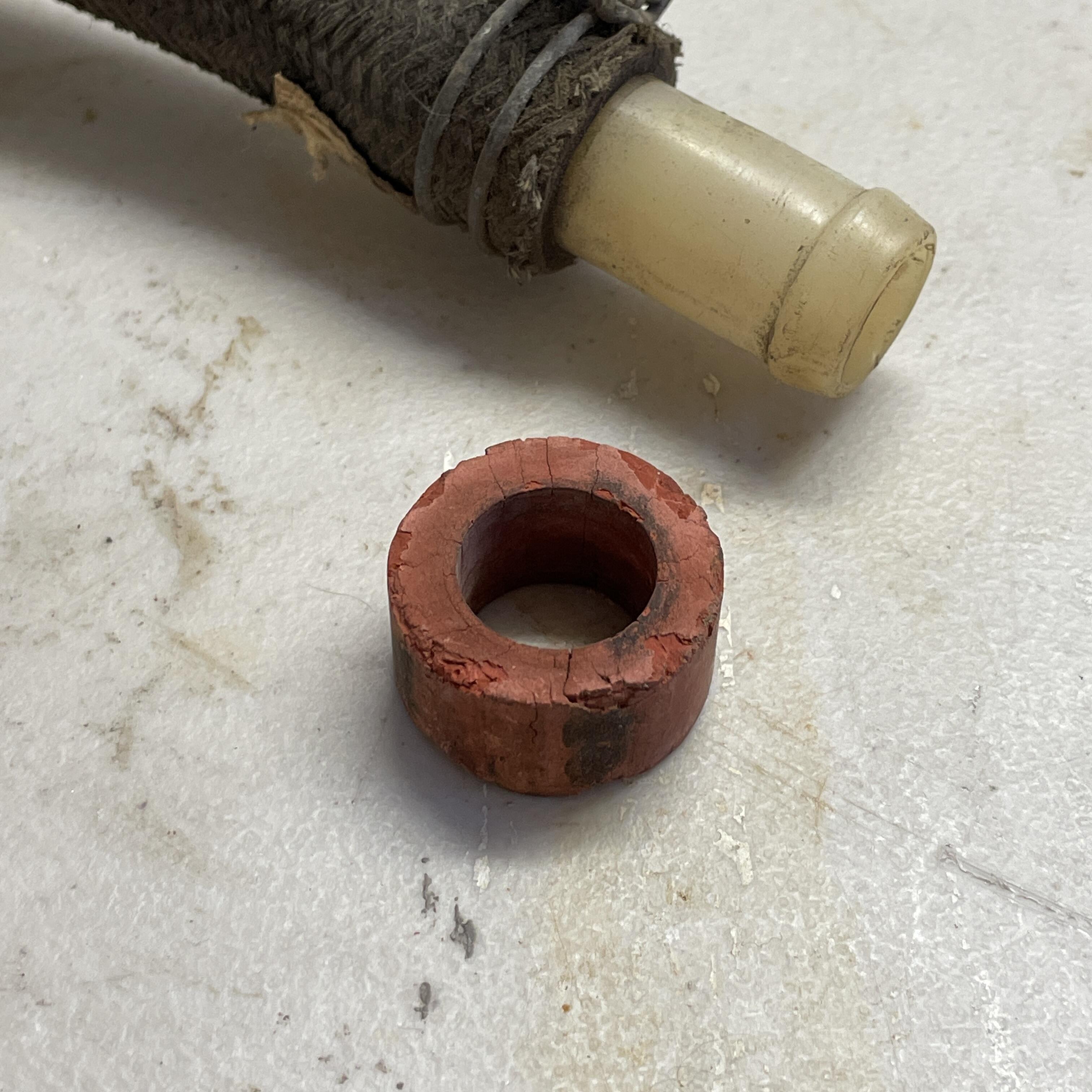
Thanks for the info everyone! Okay, quick recap: 1. The silver check valve connecting two black hoses is for the brake booster vacuum. The black and gray one I have is also a brake booster vacuum check valve. The red ring is for the silver valve. I will test the silver one. If it works I’ll use it. 2. The 240 Z did not have a check valve in the vapor lines prior to (I think) 8/73. There is one on the brake booster, one on the smog system, and a flow valve on the left inner fender for vacuum lines. There IS one on the vapor line for cars that came with a charcoal canister (9/73?). I think there is also a fuel check valve between the fuel pump and the fuel rail on FE equipped cars. *** I think I will set up the fuel lines as they were OEM and investigate having one after the fuel pump somewhere (both placement and necessity).
-
Oh jeeez. What a mess. Okay. I also have one of these in a box somewhere: I understood that to also be a brake booster check valve.
-
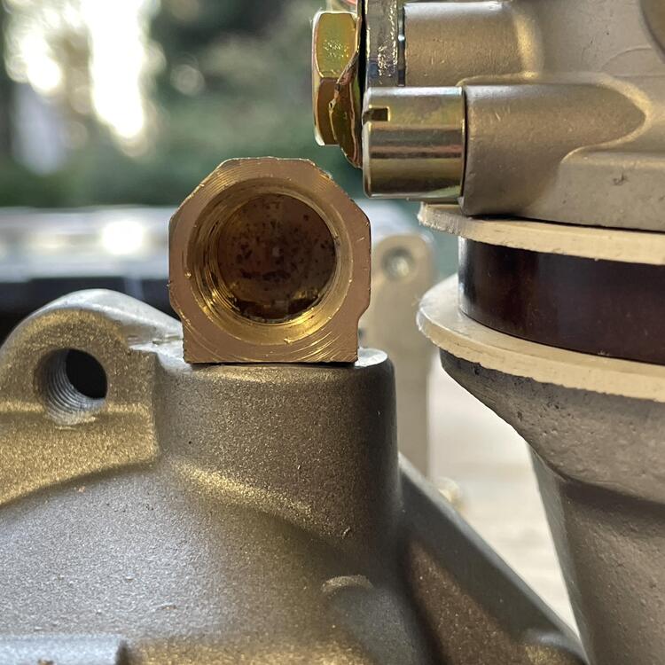
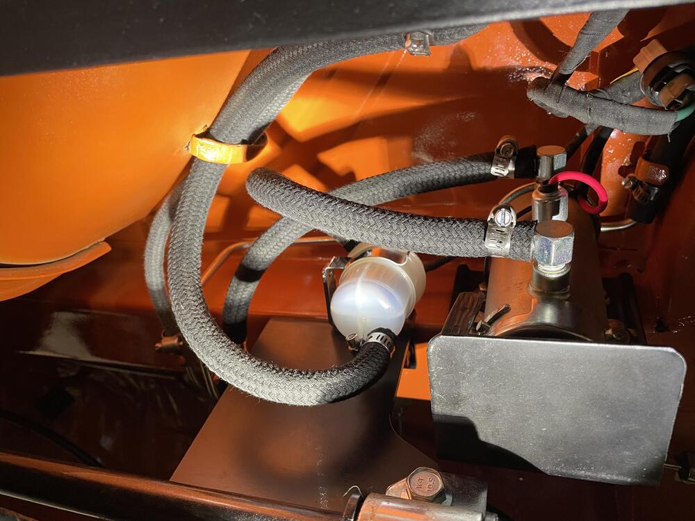
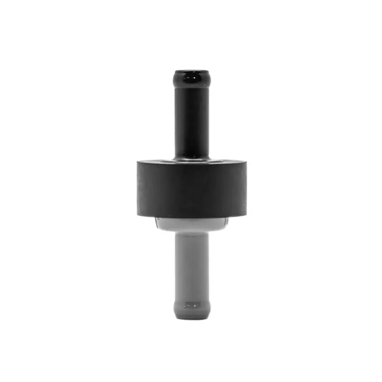
Here’s the fuel hose check valve that isn’t in the diagrams:

-
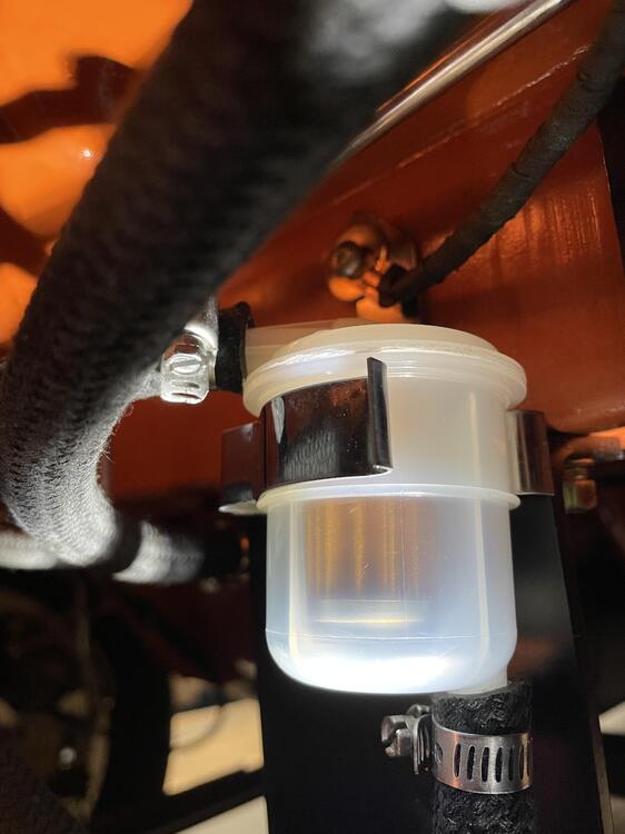
I will check that out and see if it fits. The interior diameter looks a little big compared to your photo, though. Speaking of check valves, one of the fuel hoses has one but I don’t see it in the diagram and it’s not listed in the parts for the fuel tank assembly. I am assuming it goes from the tank to the vapor canister and is supposed to prevent backflow but I’m not confident in that assumption. Any ideas? Any good places I might want to add an additional one?
-
I found this red cylinder in the box with all of my old fuel hoses for the gas and vapor tanks. Anyone have any idea what this is? I don’t see it in the exploded diagram and a search yielded zilch. Is this just some random object the previous owner put in the box mistakenly, or is this some mystery part that I should replicate? (17mm hose with plastic barb for size reference)

-
Has anyone tried the AC hoses Godzilla Raceworks makes specifically for the Vintage Air evaporator? This looks like it might be the lowest cost option to complete the AC system’s refrigerant circuit. https://www.godzillaraceworks.com/hvac/datsuns30vintageairhoses I would really like to have stainless steel hardlines for the majority of my system, but I can’t rig weld OR silver braise, so it may not be possible for me to do myself. I was also looking into Aeroquip EZ-Clip connectors and narrow hose, but I’m unclear as to the reliability of that vs beadlock fittings. These Godzilla hoses will definitely be cheaper and I won’t have to buy tools. I just don’t know if they will route the way I would want them to if I did it myself.
-
Okay, that reinforces my assumptions. I think I will put the windshield in first also. I just think I need the space to work.
-
Question about the assembly sequence: Is it better to put the windshield in before or after the dashboard. It seems that putting it in first would be easier to get the windshield in, but also increase the likelihood of damaging it (and maybe the dash). But it also seems that it would be easier to install the dash with the windshield out. Which would you do first?
-
Very cool. I may copy that, but I also just confirmed that the hose would be further away from the headers if I ran it under them next to the block than it would if I route it under the carbs. Looks like a lot of the stuff I’ve bought to solve this has been a waste.
-
No, it’s just a scratch. It’s shiny if you look at it from a different angle. There are a few of those. Thanks for looking out, though.
-
I hadn’t because of the belts for the alternator and compressor. I will take a look at that though. I’m also thinking about whether it could go under the headers instead of cramming them in between the headers and the carbs. It might actually be cooler if I get it low enough.
-
It’s forward of the runner, but it may still give me problems. I’m going to try to get the tube to work, but it’s going to take some experimenting with different hoses to do it. I may still end up doing something different with that whole setup. Regarding the studs, I think I’m going to figure out an optimal length after I get all of the plumbing worked out. I will have to pull the carbs off when I route my AC lines anyway. I have 45mm studs on there now, and I’m nearly certain 50mm will hit, so I’ll have to machine the 50mm ones down to make them work. All of this probably explains why you don’t see this manifold much.
-
Kameari makes a gusset that uses the oil pan bolts to accomplish the same thing. I’m not sure it works without their aluminum oil pan, though, which is thicker.
-
The Mikuni studs can’t be much longer because they will hit the manifold when it’s tightened down. I might be able to add 5mm but not more. same story with the carburetor studs. Thanks. Yeah, they are a ZX thing. They were also used on some L20 configurations.
-
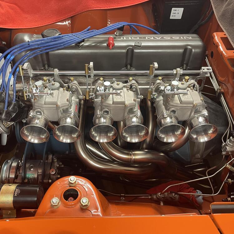
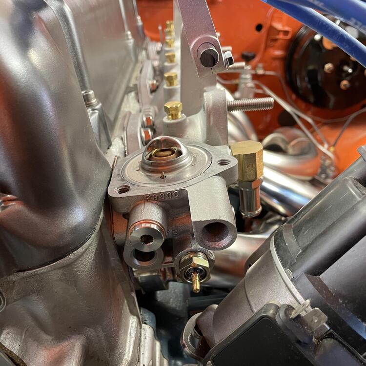
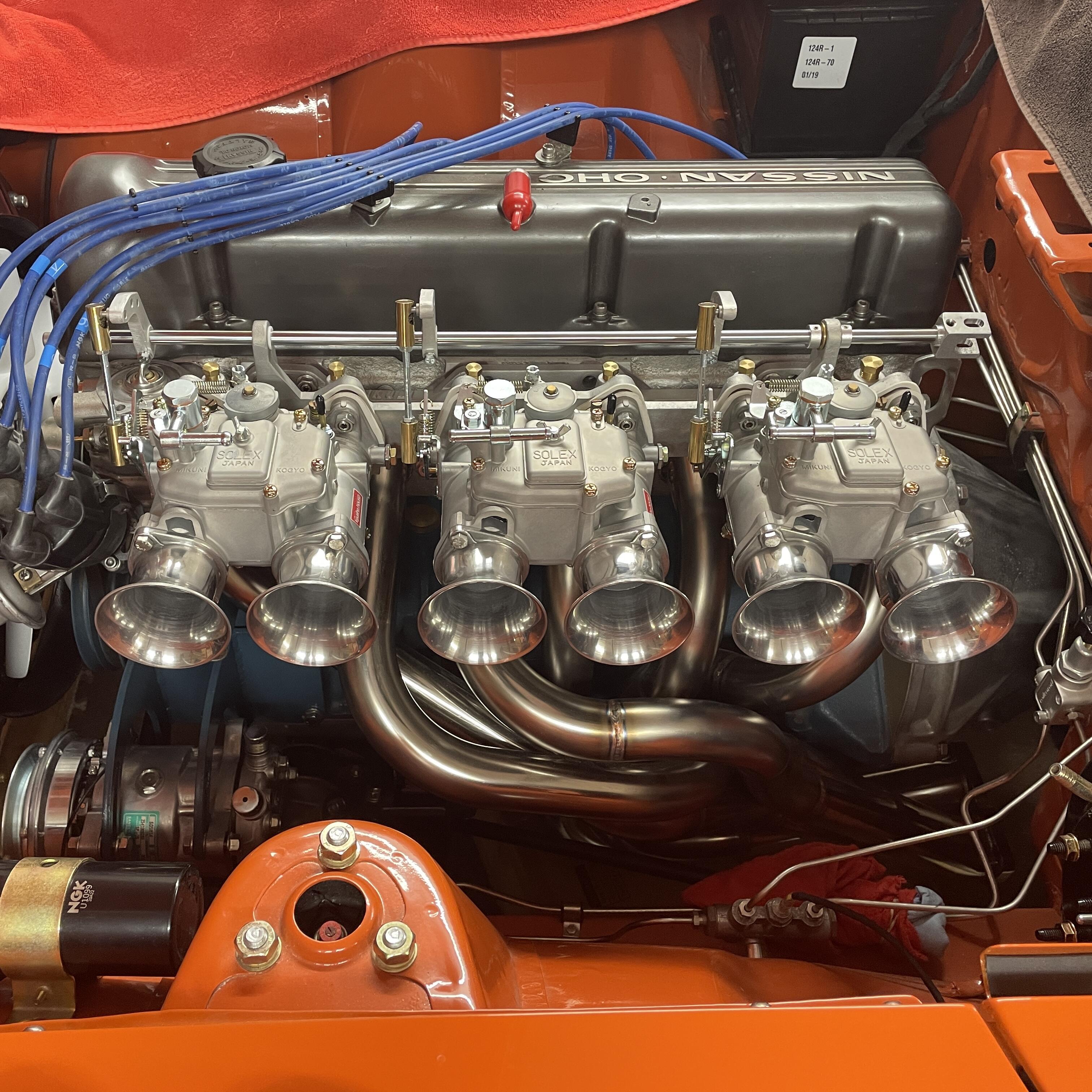
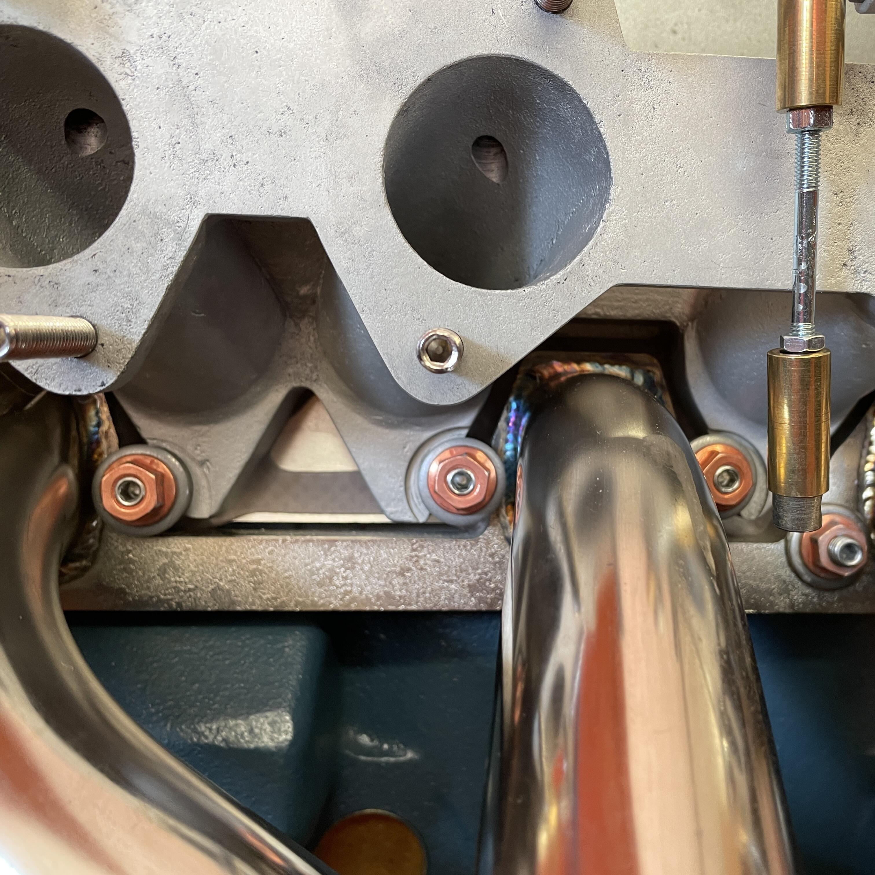
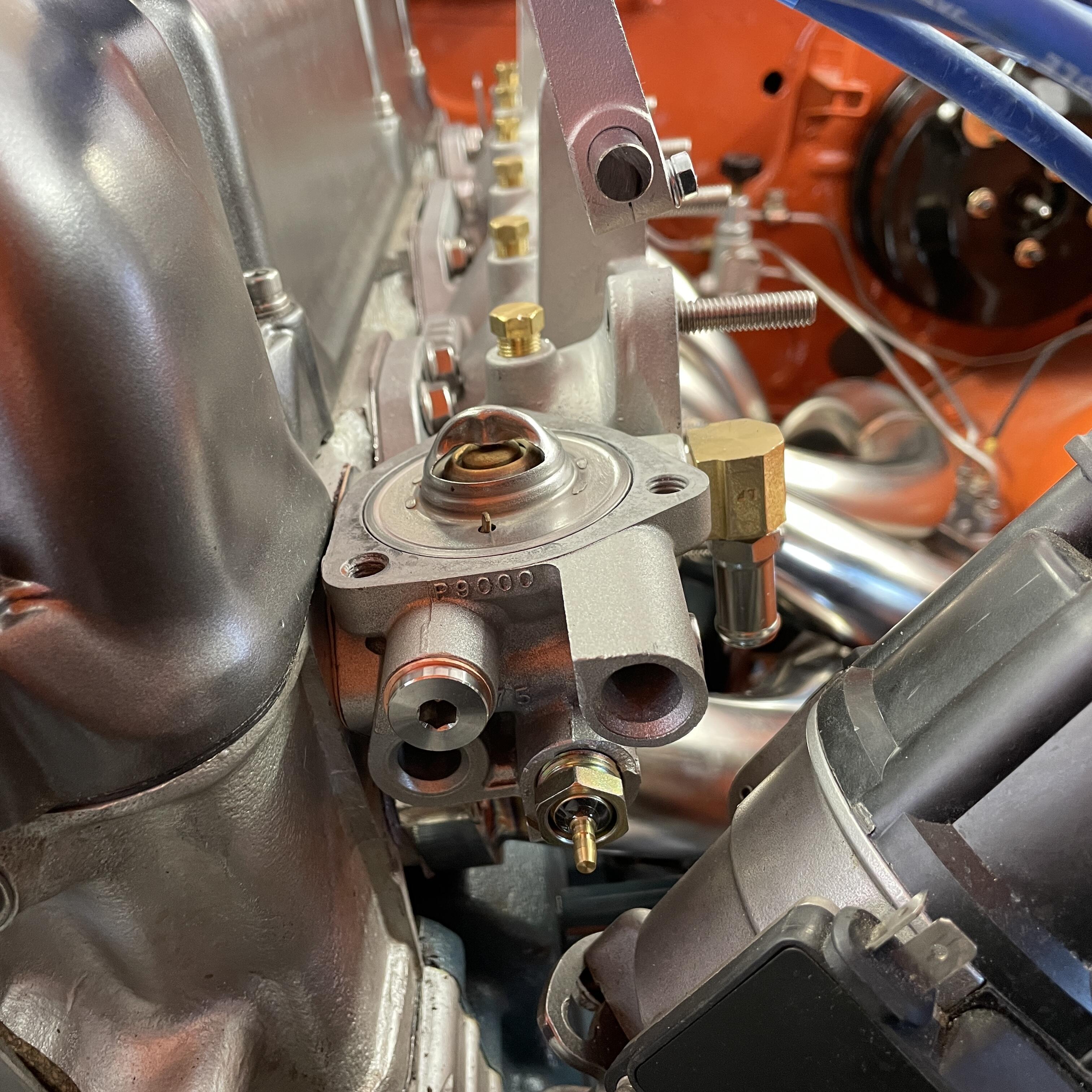
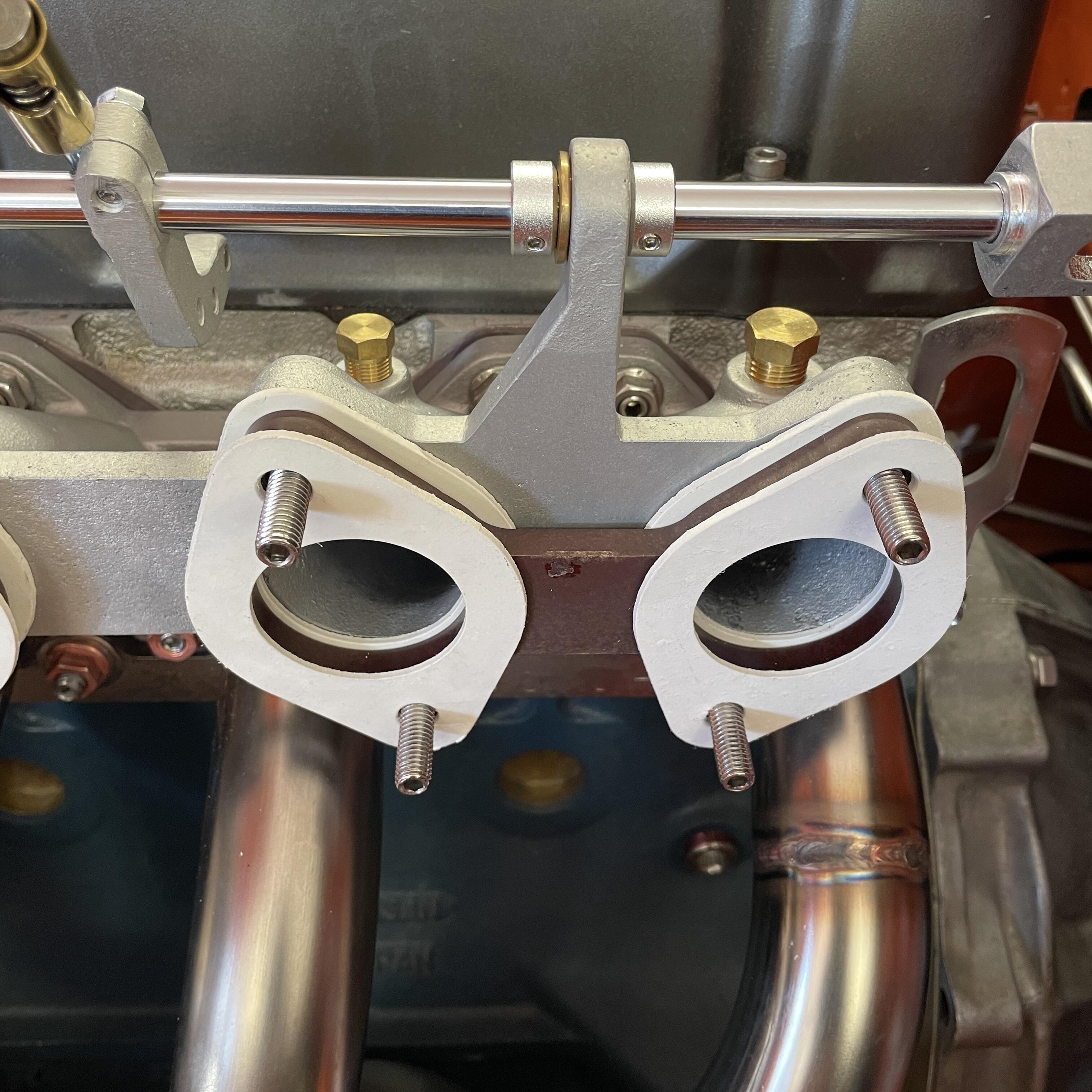
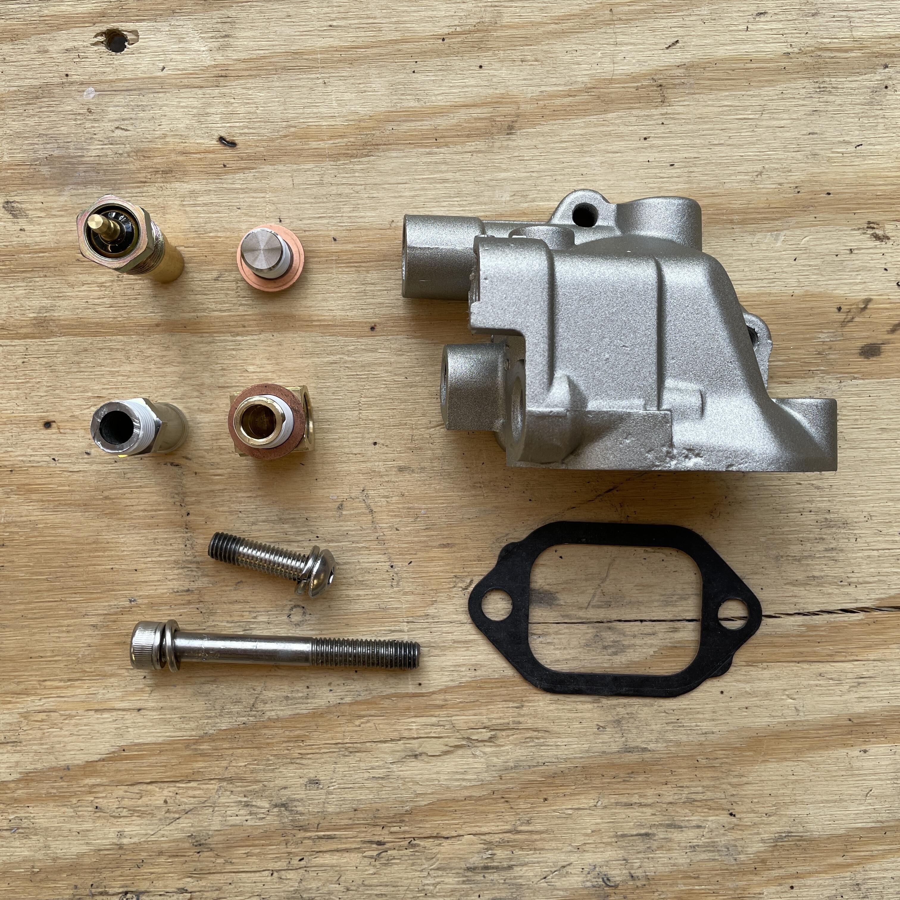
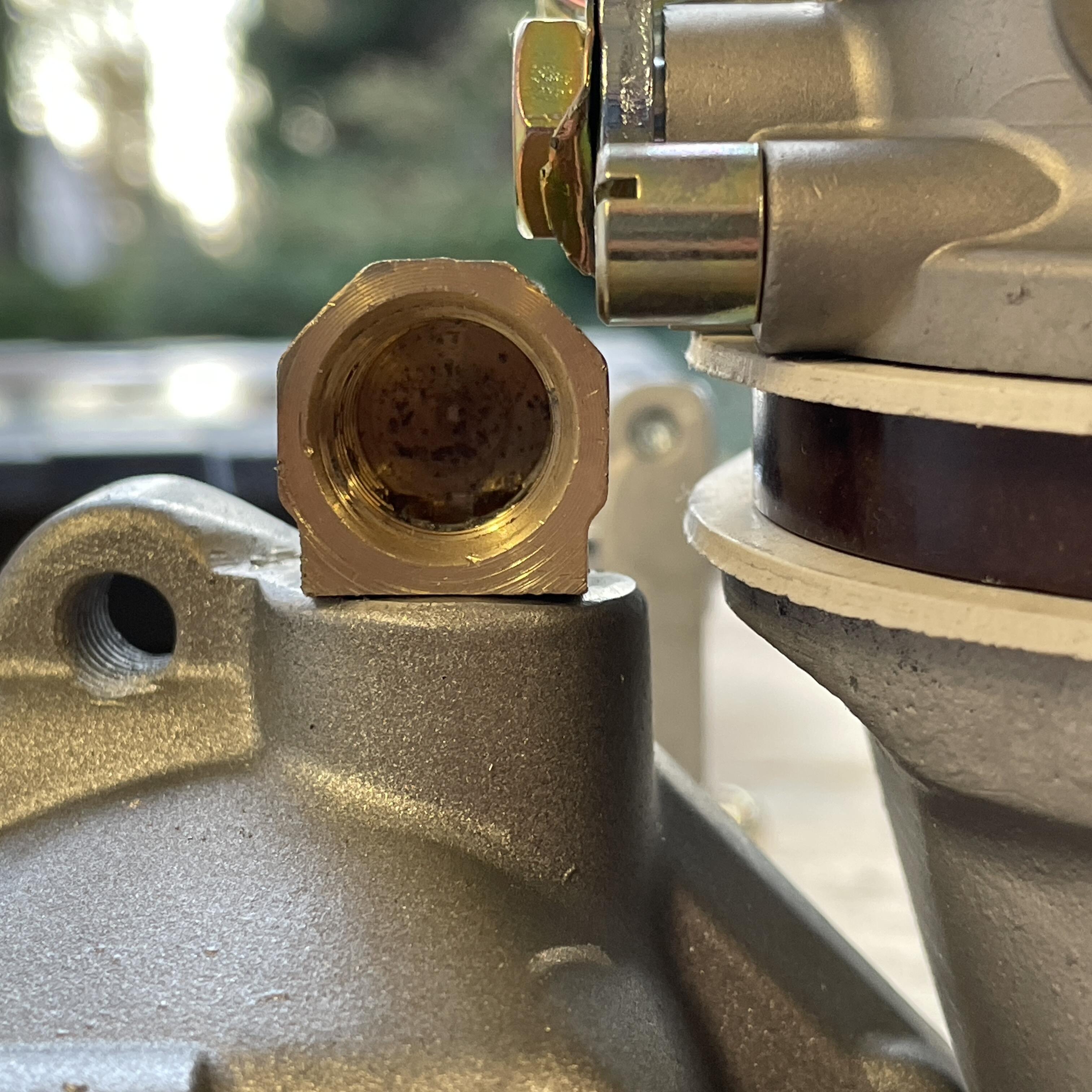
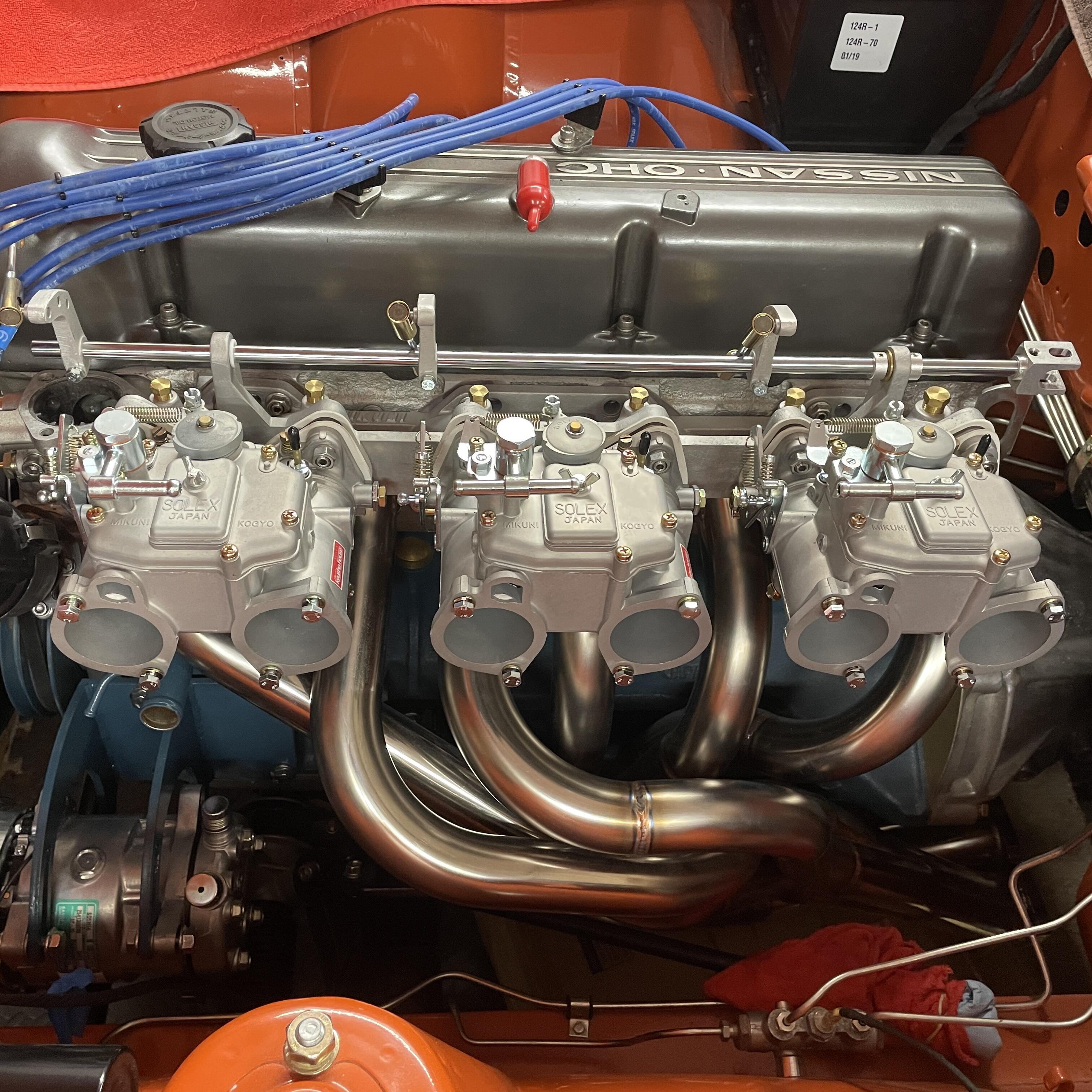
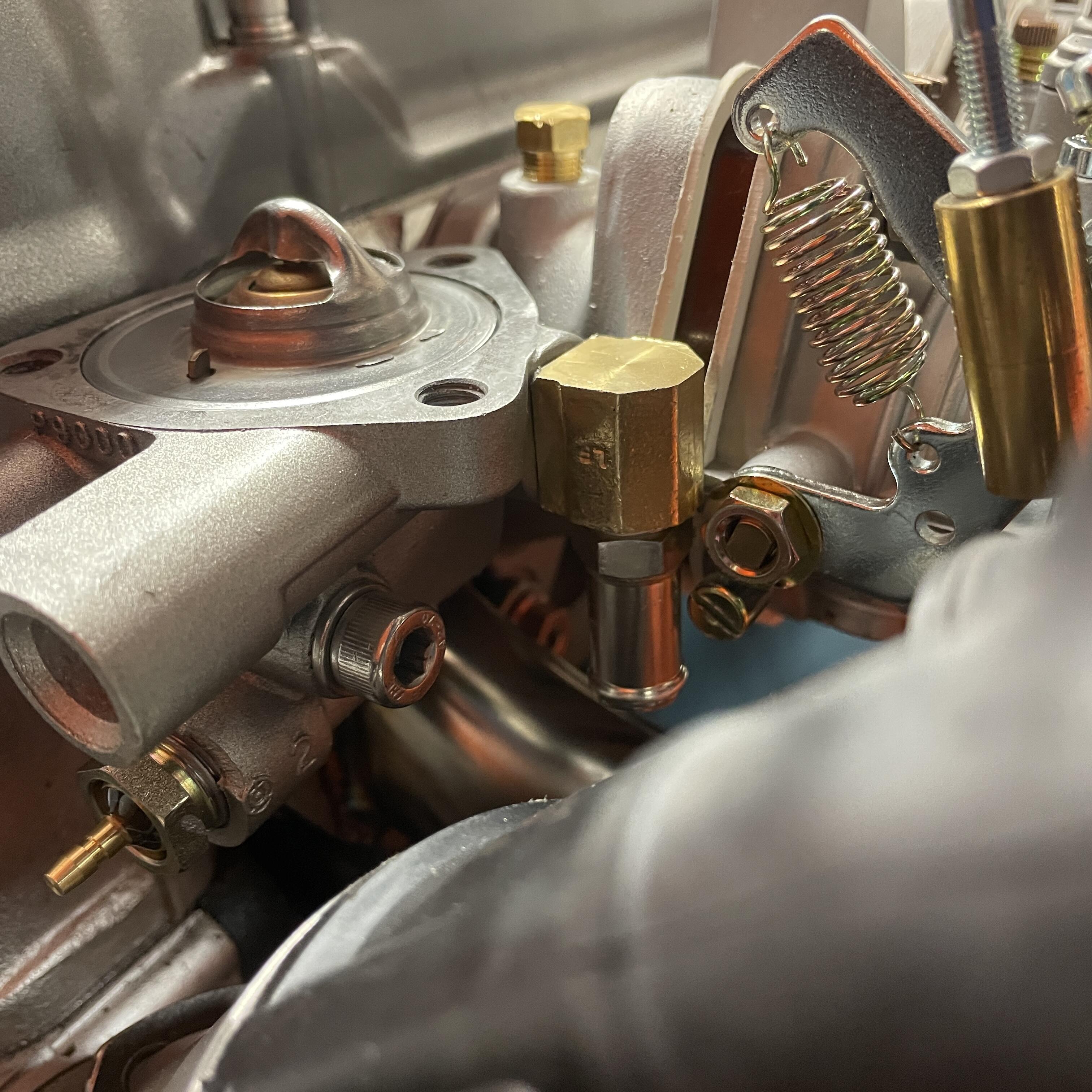
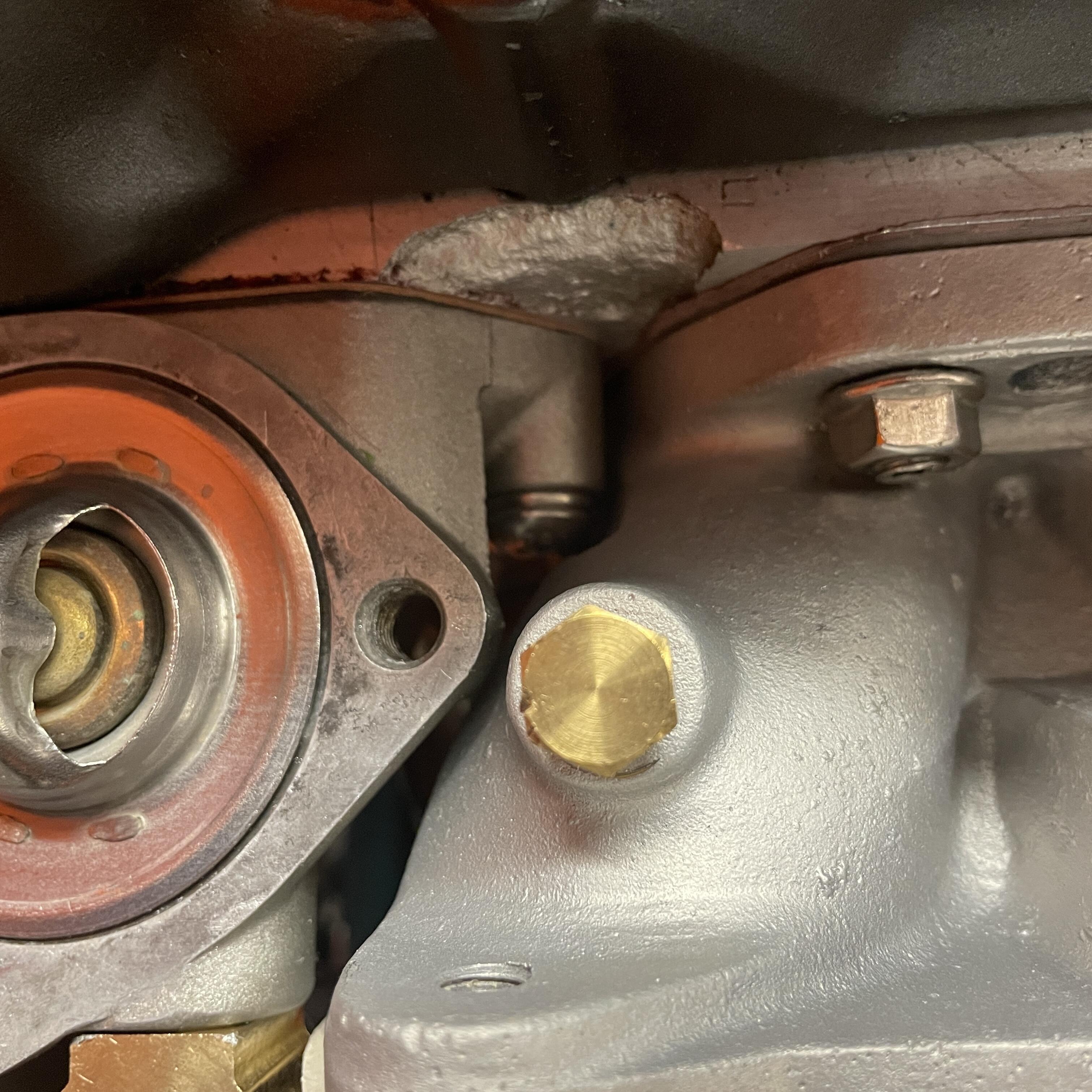
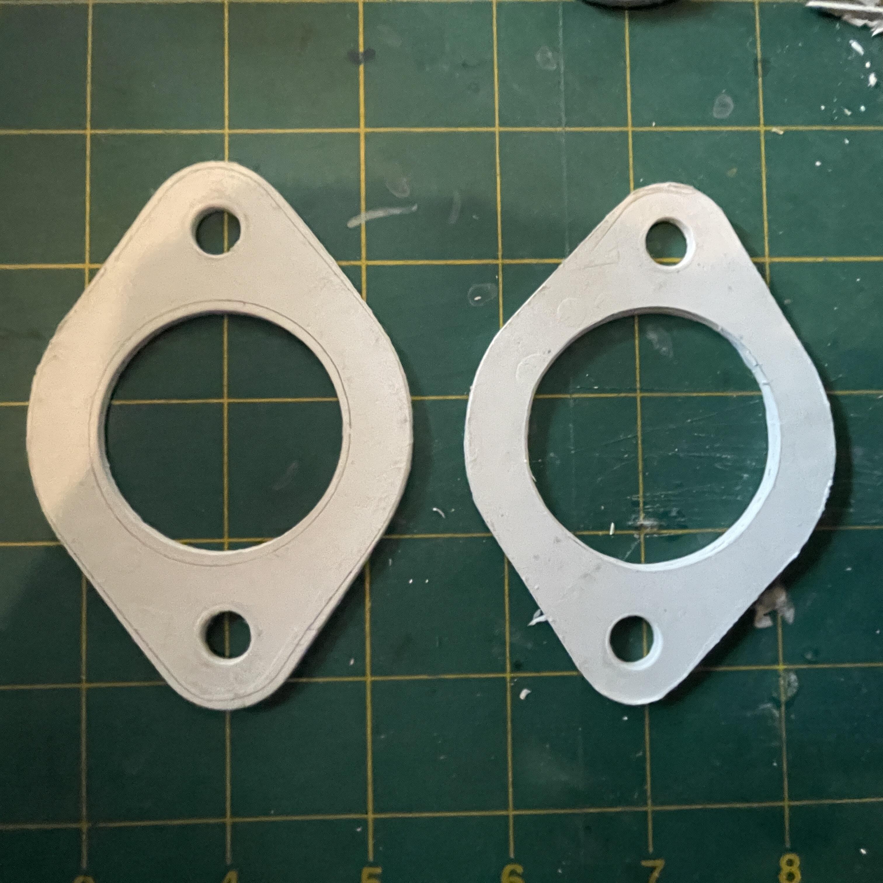
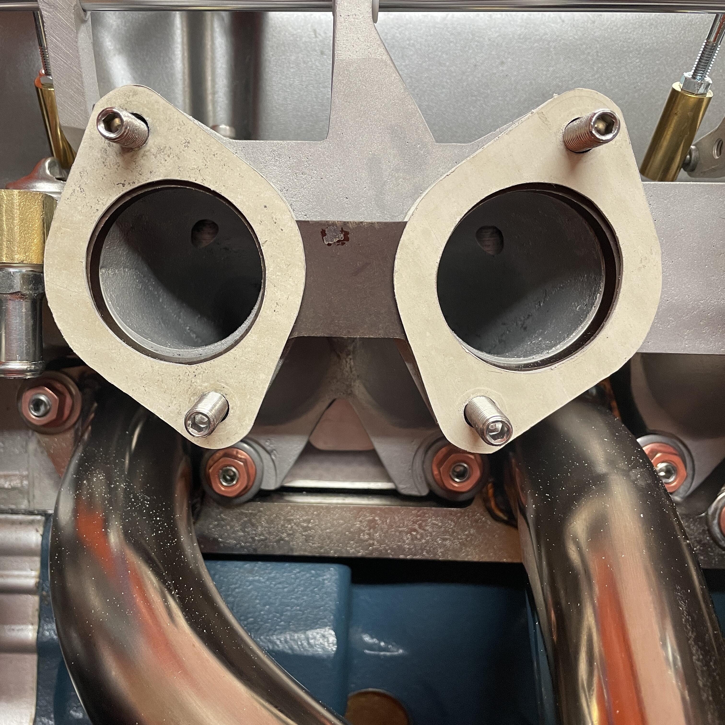
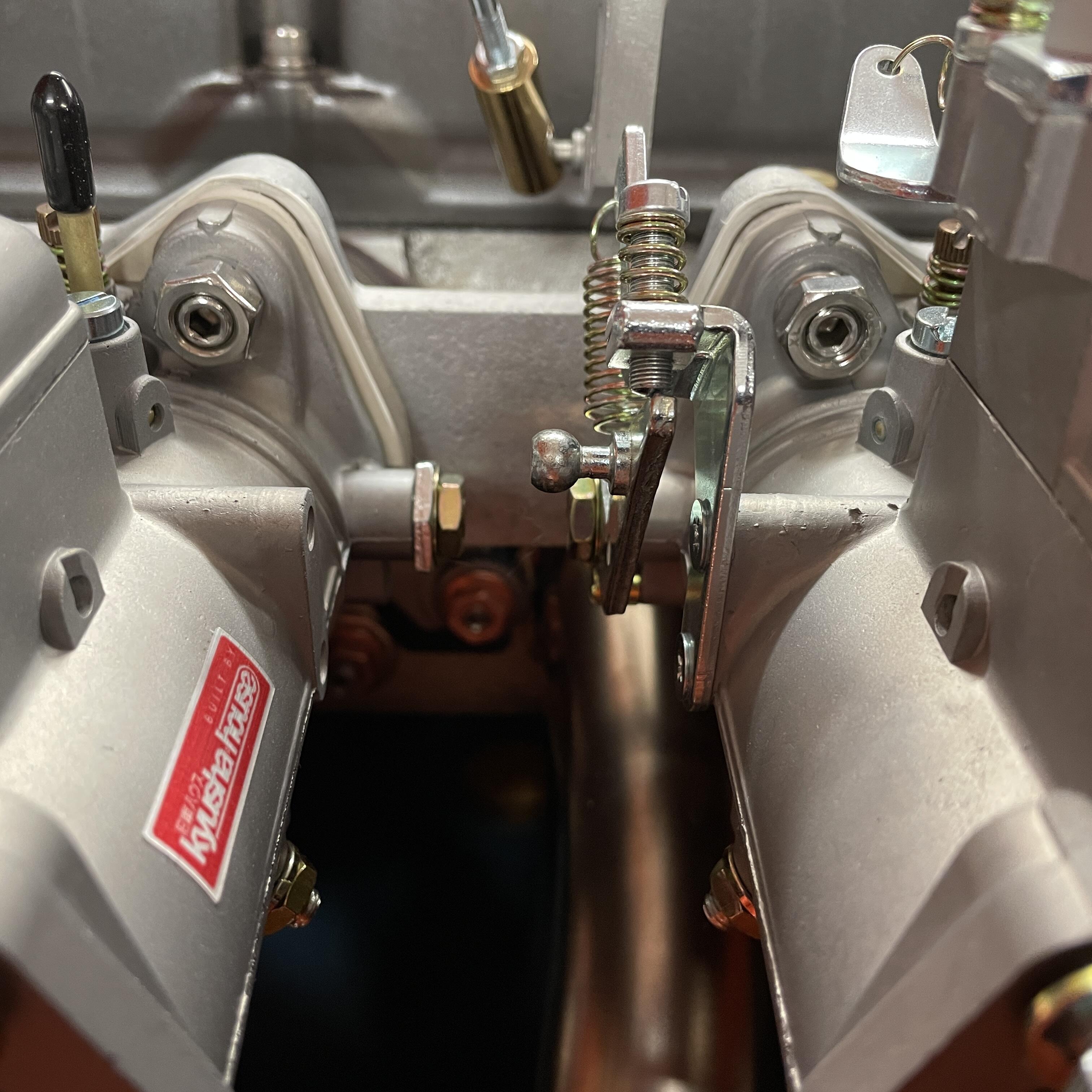
My Mikuni 44PHH carburetors are in. This. Took. Some. Work. They are fitted to a Mikuni short-runner intake manifold, which sounds all well and good until you try to fit it along side a 240z thermostat housing, which fouls the manifold. I had to switch back to the ZX housing. It doesn’t interfere with the manifold installation, but it’s cover sure does. Also, the water inlet for the coolant fouls the front carb and the throttle linkage. I want to retain a functioning heater, so I need that water pipe to work. I tried a bunch of stainless adapters, which were all much too big, but was saved by this little brass guy from Home Depot (a 90° 1/4 npt M to 1/4 npt F street / adapter). I still had to drill it out to increase the flow, as well as tap both the adapter and the thermostat housing and cut down the water inlet pipe to ensure a high rate of flow through the whole junction. I also replaced the thin black carburetor gaskets that came on them with VW carburetor base gaskets by EMPI from JBugs California Pacific. I was a little bummed to find out that they are white and not the grey in the photos, but I am pleased with how thick they are. That extra few millimeters helped push the carburetors away from the thermostat housing and gave me some much needed clearance. The gaskets are the perfect thickness for want I needed when it came to making clearance, but they aren’t an exact fit for the PHH carbs. They’re meant for VW solexes (so downdraft) and the bases are different, which meant I needed to trim them to no be sticking out a mile. They also needed to be opened up from 40mm to 44mm to not interfere with the airflow. On the left is one with the outline of the gaskets that came with the carburetors drawn in pencil. On the right is a trimmed gasket before final cleanup. In the next photo you can see that the holes are now the same size as the phenolic. They are slightly bigger than the carburetors and manifold, which I think is fine. If I have trouble I’ll make something from scratch that is custom to each port. The last photo just shows that they don’t stick out a mile anymore, even though I could probably trim them further. For the thermostat cover, I took a gamble on a NOS one for L20Bs and JDM C210 Skylines for $20 on Amayama. It looks like it uses the same gasket as the ZX, so hopefully it will fit. It looks just like the three-bolt ZX cover, except it doesn’t have the two extra bosses on the rear end, which hopefully means it won’t hit anything. We will find out when it arrives. Now on to the goodies: the carburetors are 44mm Mikuni PHH side drafts (I explained in an earlier post how I got them). They are on the previously mentioned Mikuni short intake manifold, held on with OEM manifold washers and copper flange nuts on the bottom and SS flange bits on top, and wearing 50mm Kameari velocity stacks. Next I plan to fit the heat shield and solve the water pipe routing problem. I have air filters but don’t expect to mount them until the brake and clutch master cylinders are in and the fuel routing is worked out.