Matthew Abate
Free Member
-
Joined
-
Last visited
Everything posted by Matthew Abate
-
 Rad! Thank you. I had no idea what they were called.
 -
Thanks. Another question… Is it possible to buy the little ends that are crimped onto the wires that go into the connectors for the dash bulbs? I’m talking about the ones that are like a split cylinder with a hemisphere on one end and make contact with the bottom of the bulb. If so, what are they called? I’m struggling to find them when I search.
-
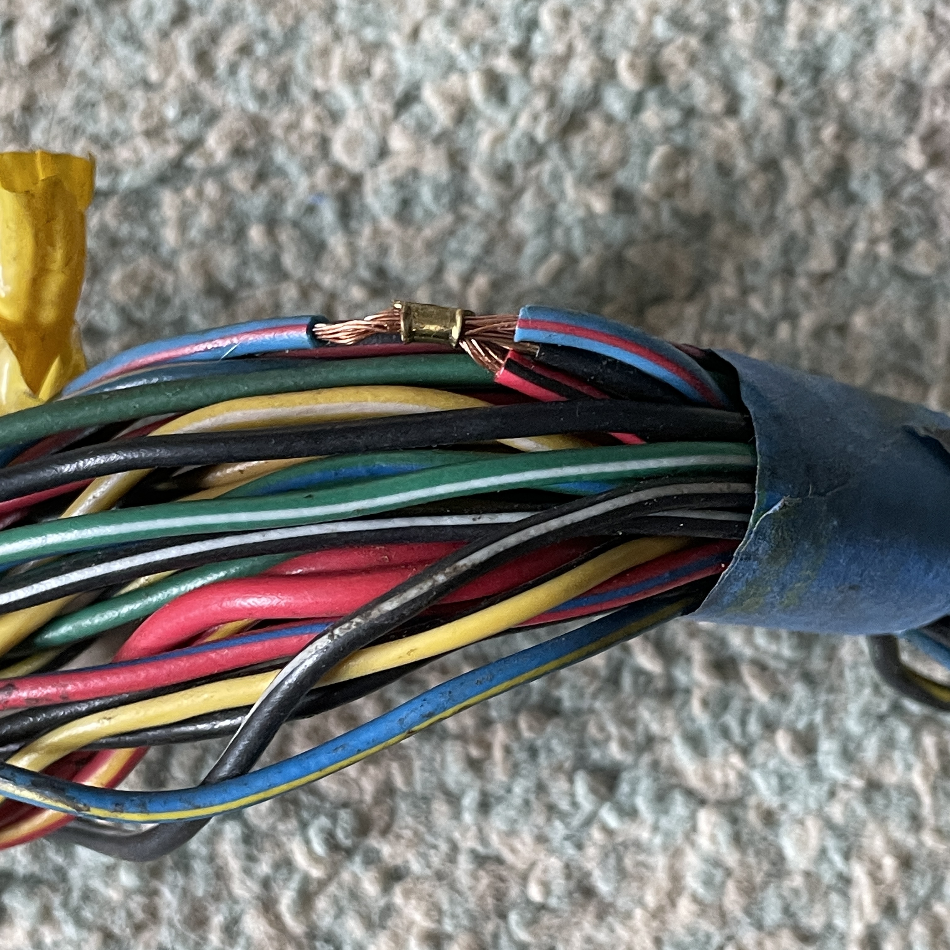
One of the factory tape wraps came off a splice on my old harness and I noticed this: I don’t know if they did that from the factory or if this is a repair. I have a few other splices where the tape came off and they don’t have this clamp wrapped around the wires. I’m inclined to think it’s from the factory, though.

-
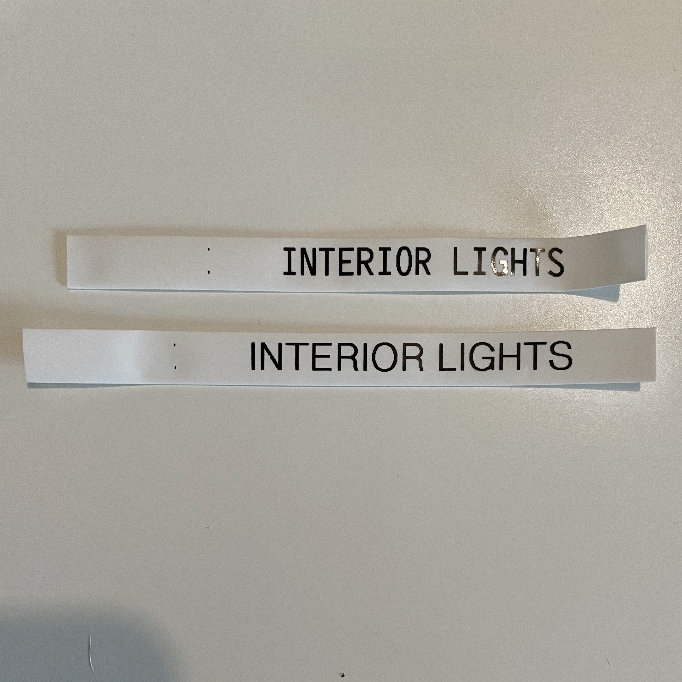
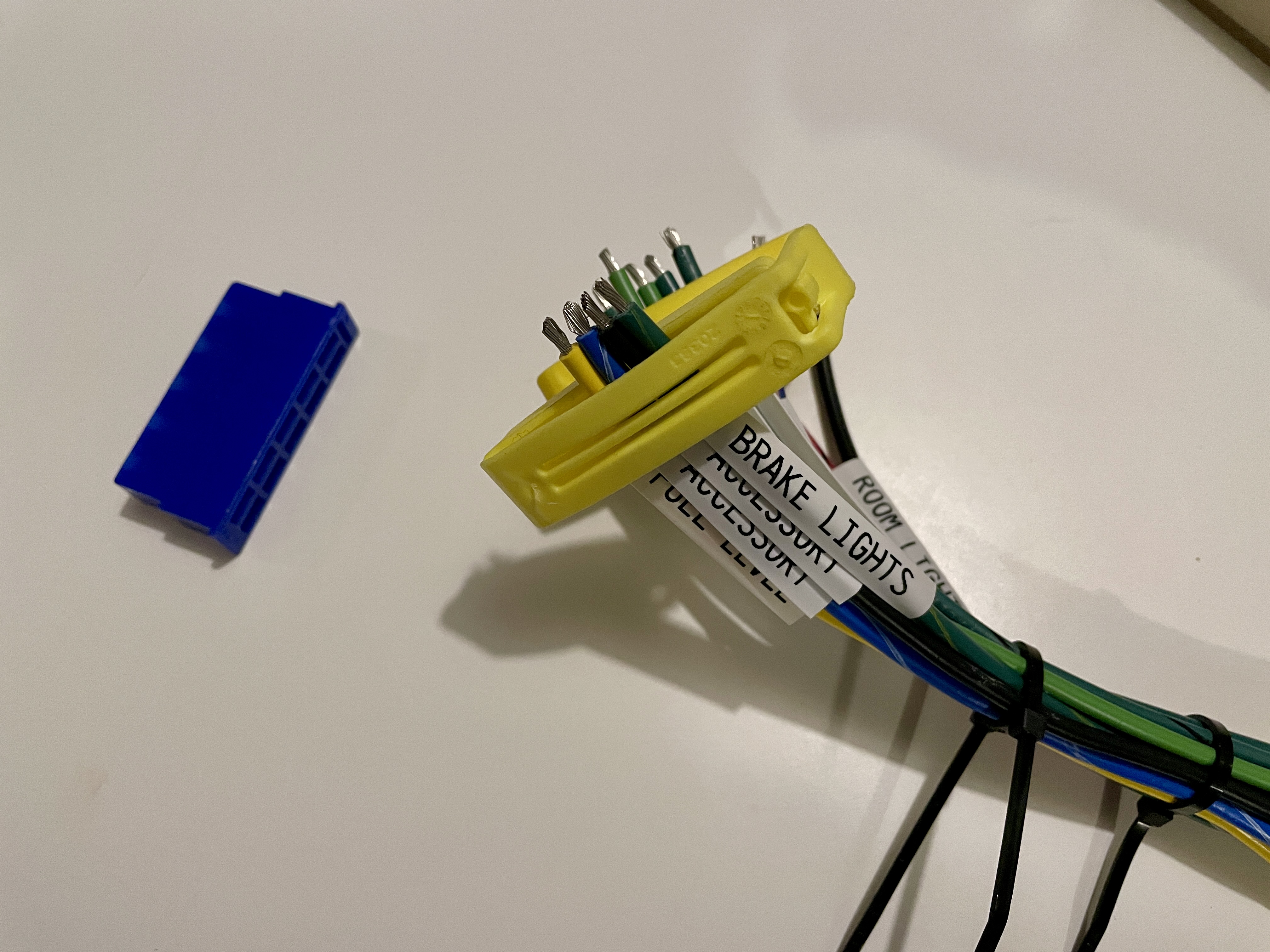
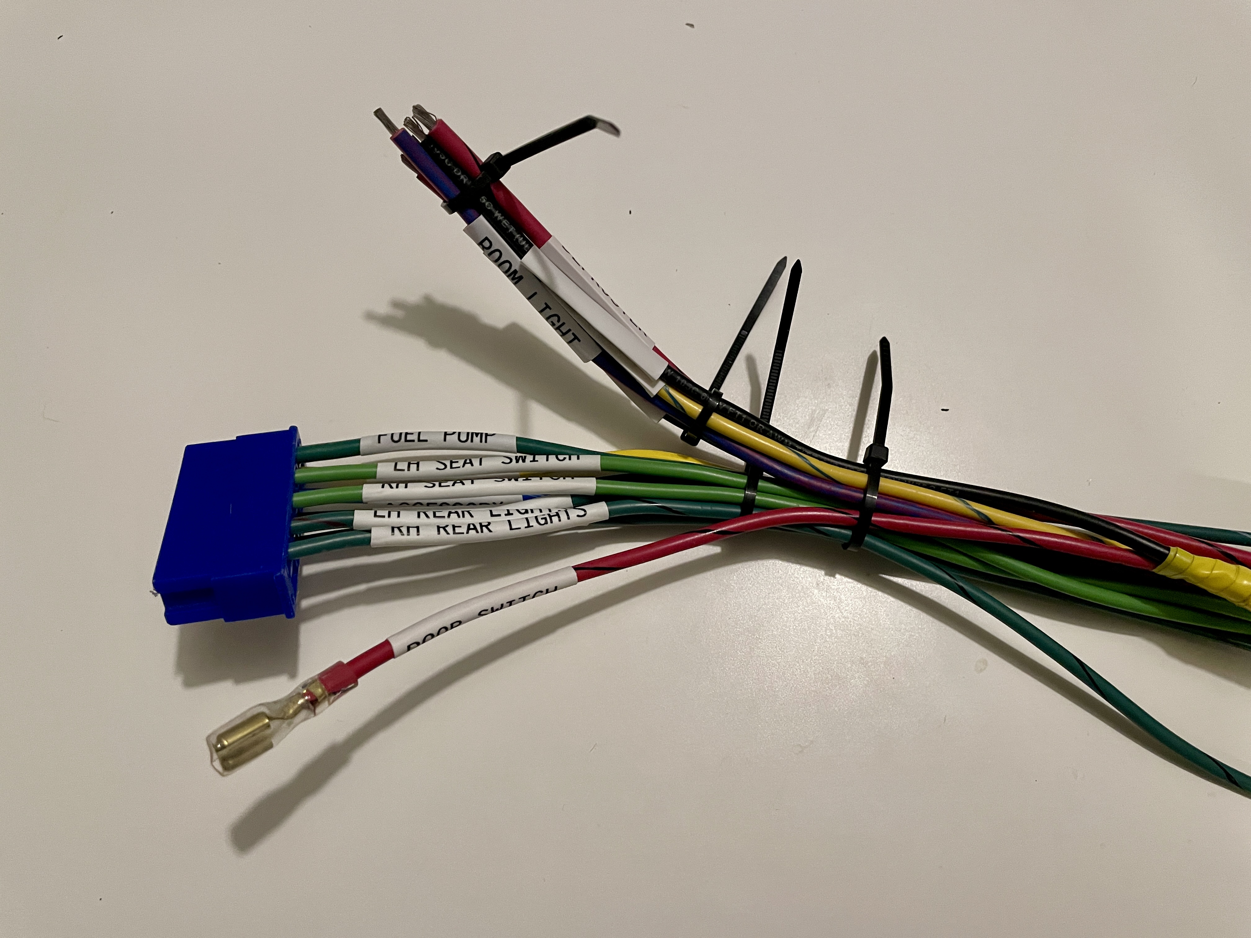
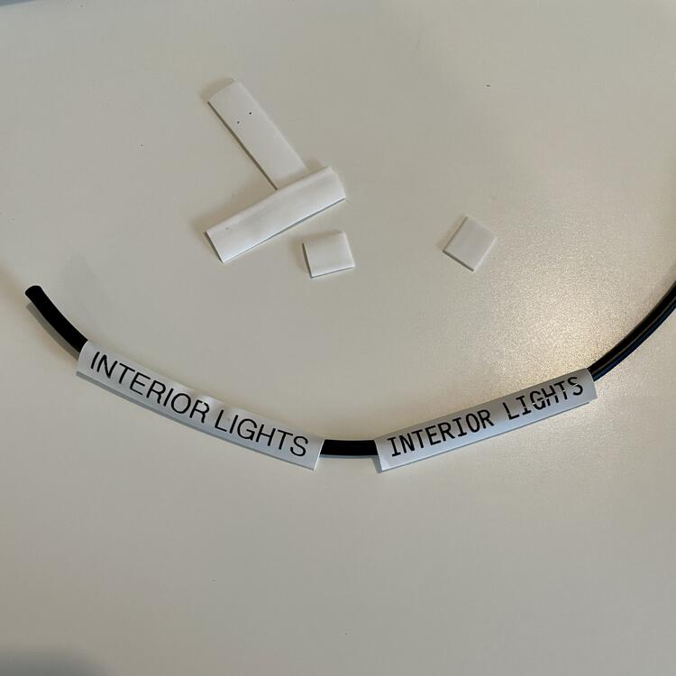
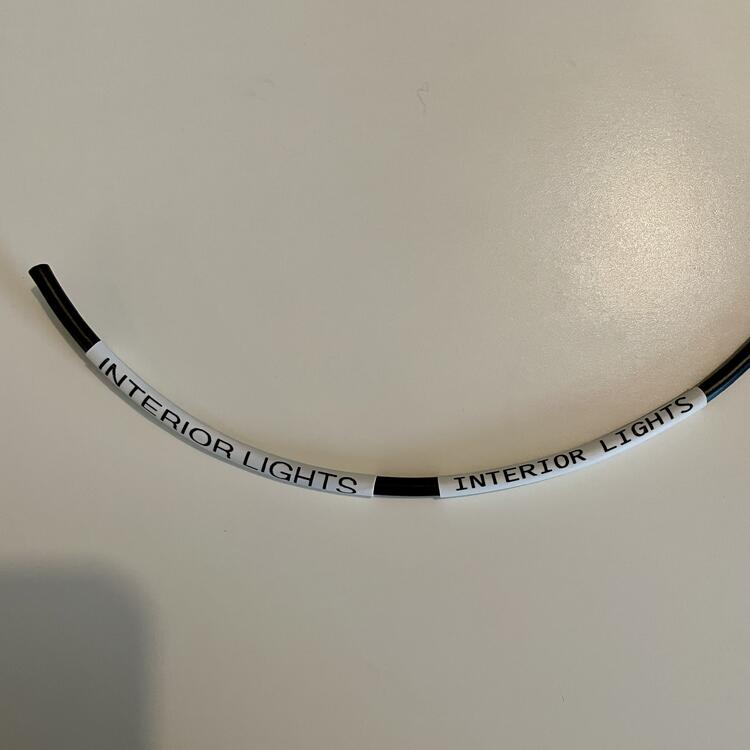
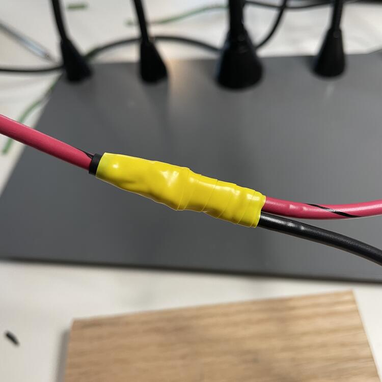
I’m well and truly in it now! I put the OEM color coded connector onto my new custom body harness, so I’m committed. No problems really other than putting the first terminal on upside down so the label wouldn’t have been visible. It was a pain to get off so I know my crimps are good. 😁👍🏻 Now I know not to shrink the labels until after the terminals are on the wire and properly aligned to the connector. The shrink wrap labels are what I’m really showcasing here, though. I got this trick from a guy I knew in the IT team of one of my past jobs. They would label all of their Ethernet cables like this so they didn’t have to chase wires later. These HSE label cartridges are what was holding me up. I had ordered 5.8mm, which looked really clean and tidy but is too small for this marine wire with it’s crazy thick insulation, so I had to order some 8.8mm. But it’s a breeze to put on. The only thing I would improve is making the label maker print on both sides, which is too much to ask for low end office equipment. Heres my test fit with the 8.8:


-
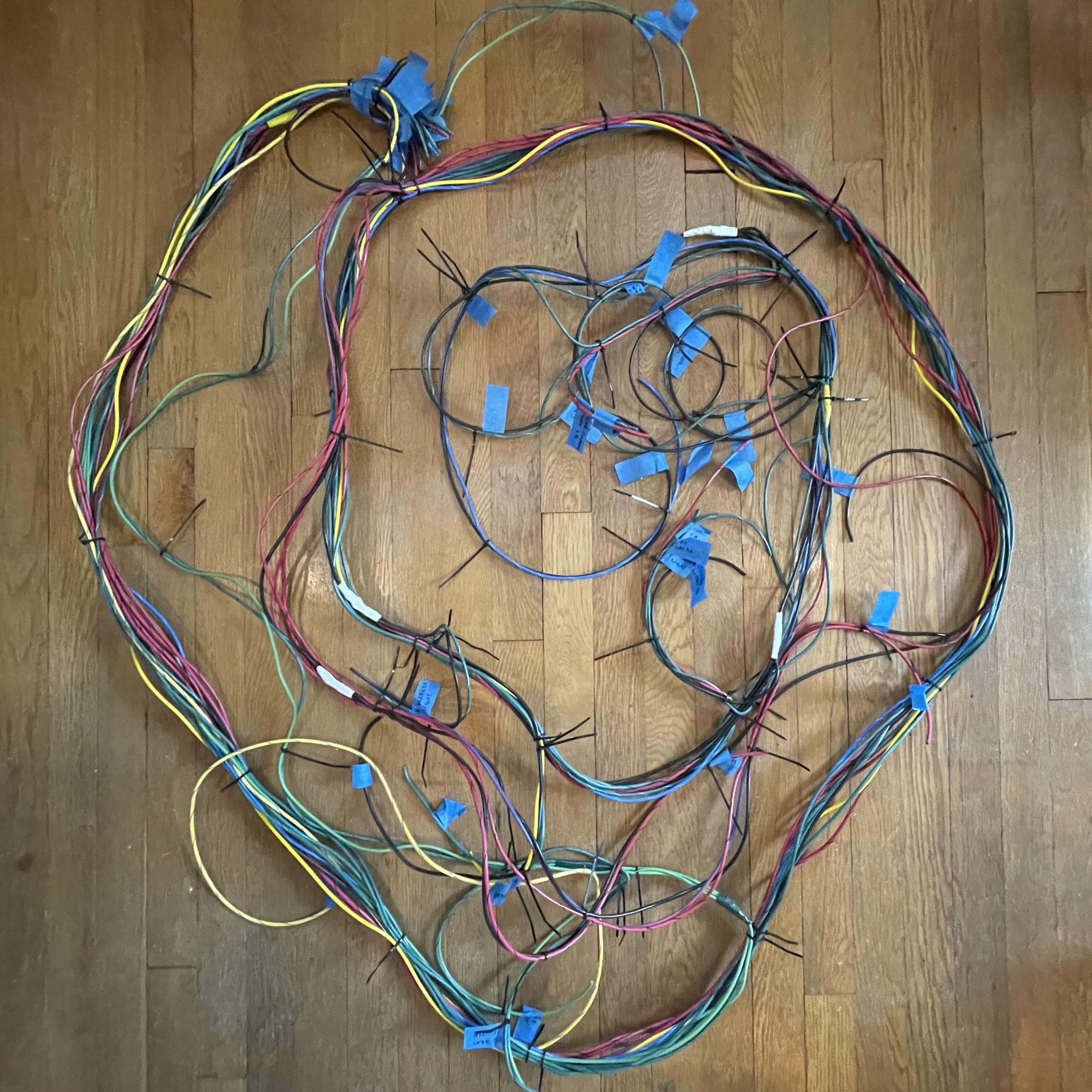
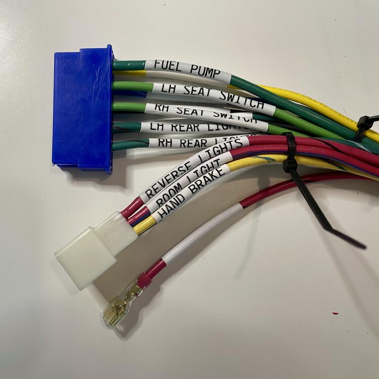
Finished the wiring part of the body harness. All of the splices are strong and I have good continuity throughout, with no more than 0.20 Ω of resistance on any given wire. All of the branch points are zip tied in the same locations as the OEM harness, so it should lay in just fine. The next step is a test fit inside the car to make sure. Separately, I was wondering if anyone knows what the blue tape Nissan used to tack down unused optional wires is. I was thinking of using blue strap tape like they use on appliances, but if there’s a way to get the real thing that would be better.
-
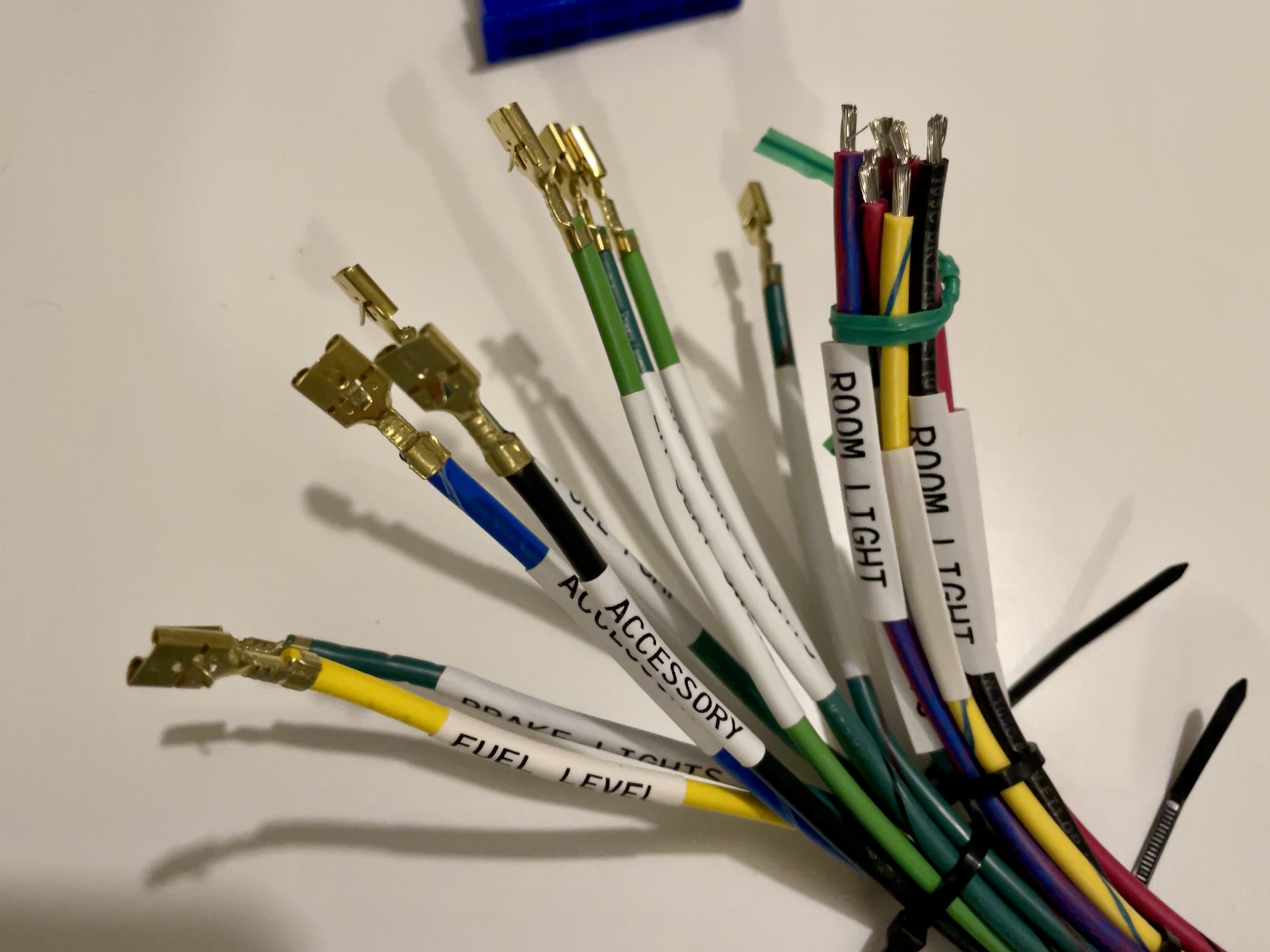
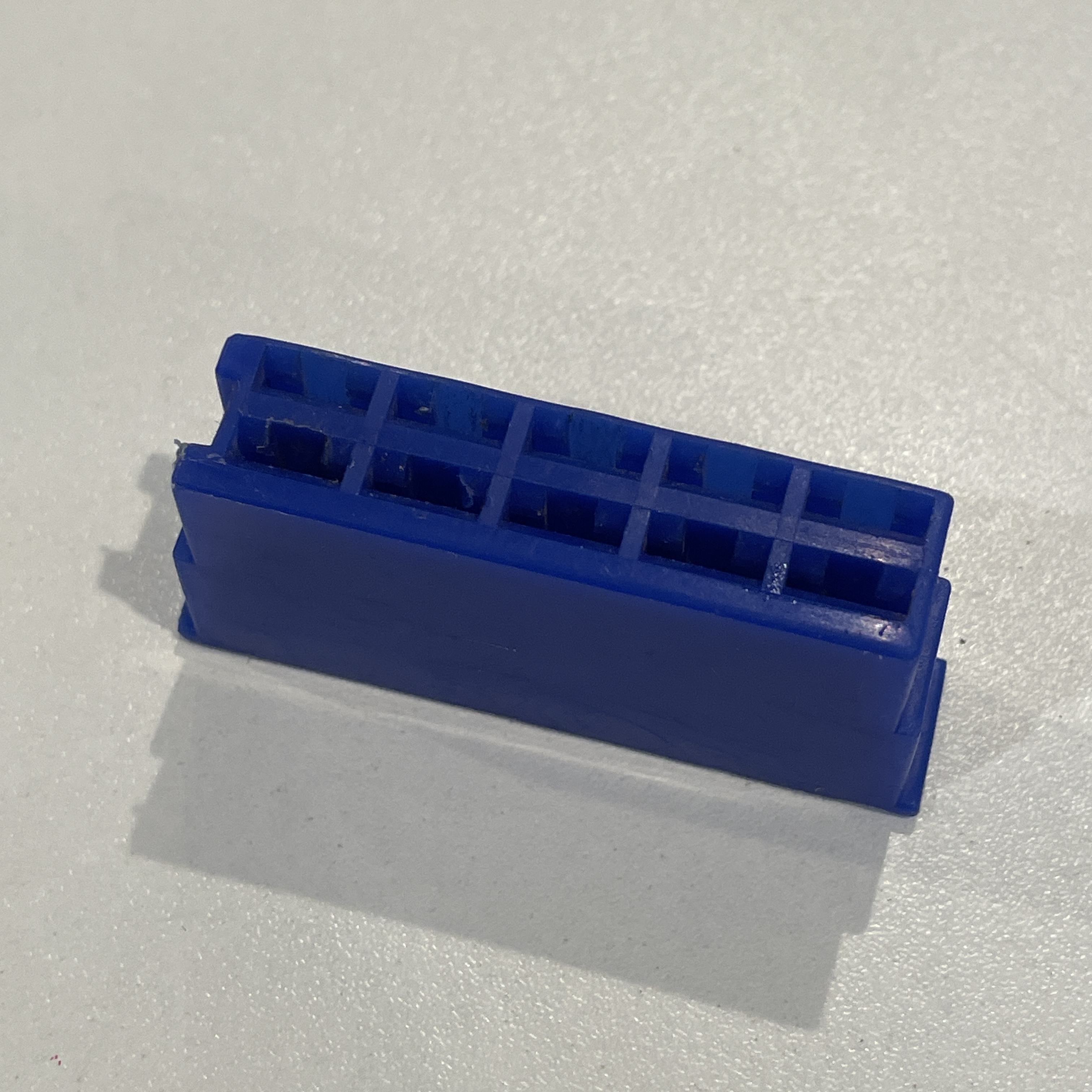
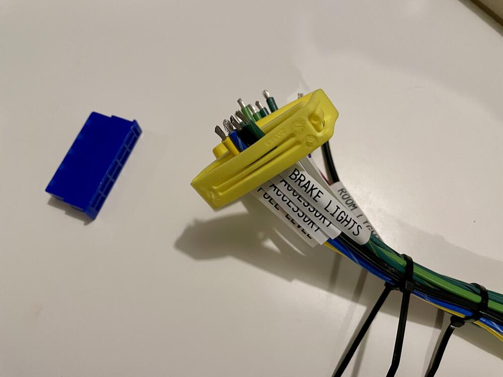
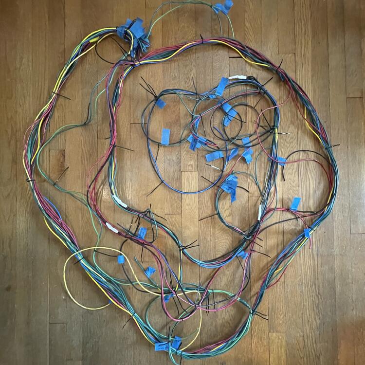
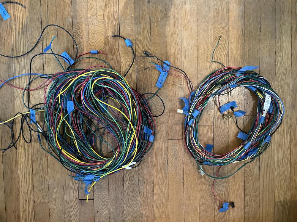
Made some major progress today! First, I was able to remove one of the colored connectors from the OEM body harness without any damage, and it looks like I should be able to source new spades for it with no trouble, so that’s a relief. Second, I finished cutting and splicing the wires for the body harness. Im not sure if you can tell, but mine is definitely beefier than the OEM harness. The overall circumference of all of the bundles together isn’t that much more, but it’s definitely weighs more. So now I need to test all of my splices with a multimeter and then put zip ties at each of the branch points. After that is heat shrink labels on each end and the colored connectors, then on to the next. Once that’s done for each harness I’ll lay them out and get the terminal connectors on, then wrap them.

-
I started assembling the body harness this week. I figure if the thicker insulation of the marine wire is going to be an issue it will be in the dashboard. The body harness doesn’t have to get crammed into a tight space the way the dash harnesses do, so I’m safe on this one. I’ve cut the 15 main wires that come from the two connectors at the firewall to the same length as the original wires plus an extra 14 inches to allow for putting on my connectors and any discrepancies in my measurements as I go along. For splicing I’m referring to a guide that my dad pointed me to. It’s a supplement written by Ford for for techs to work on ambient lighting in trucks and has some good diagrams for various types of splices. Here’s a PDF: 2013_truck_ambient_lighting_9-25-2012.pdf Some of the splices are a little chunky for my taste, but they’re super strong even without solder, so I’ll continue referring to it. Here’s a finished Center Splice (the first example in the guide) connecting the door switch to the wire running to the room light without cutting any wires: I’m using heat shrink on these to seal them up, but I’m also wrapping them with tape in the same colors Nissan used for referencing purposes. This particular tape came from Identi-Tape and is really nice and would probably be enough, but I have the heat shrink so I’ll use it too.
-
1983 280ZX with P90 head, custom 87mm domed and relieved pistons on L24 rods (9.8 compression), 45mm headers from Spirit garage in Japan (not Datsun Spirit).
-
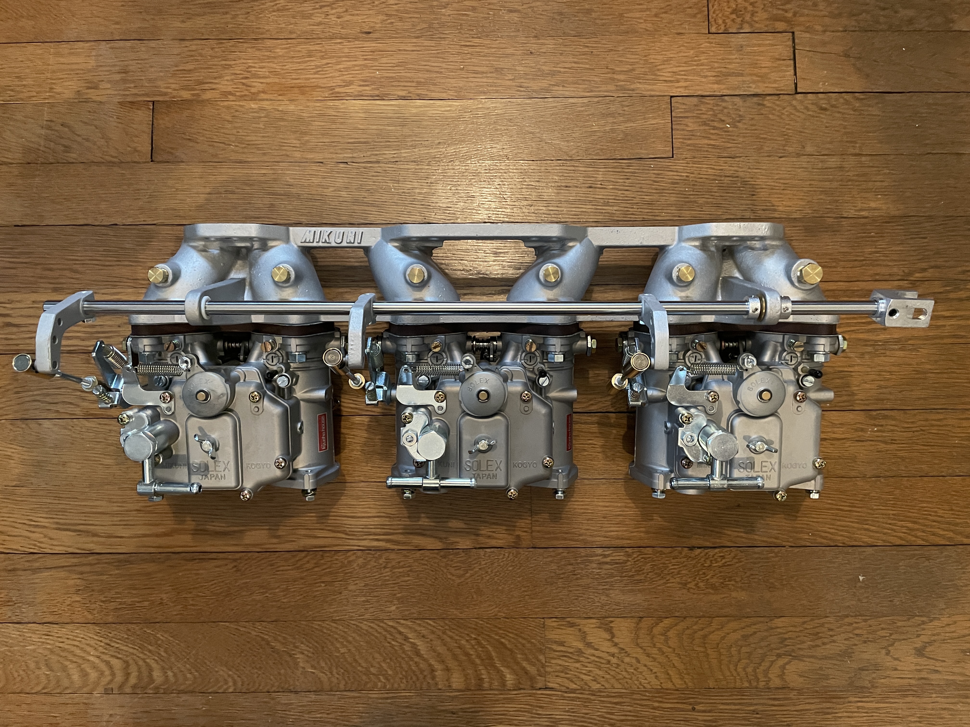
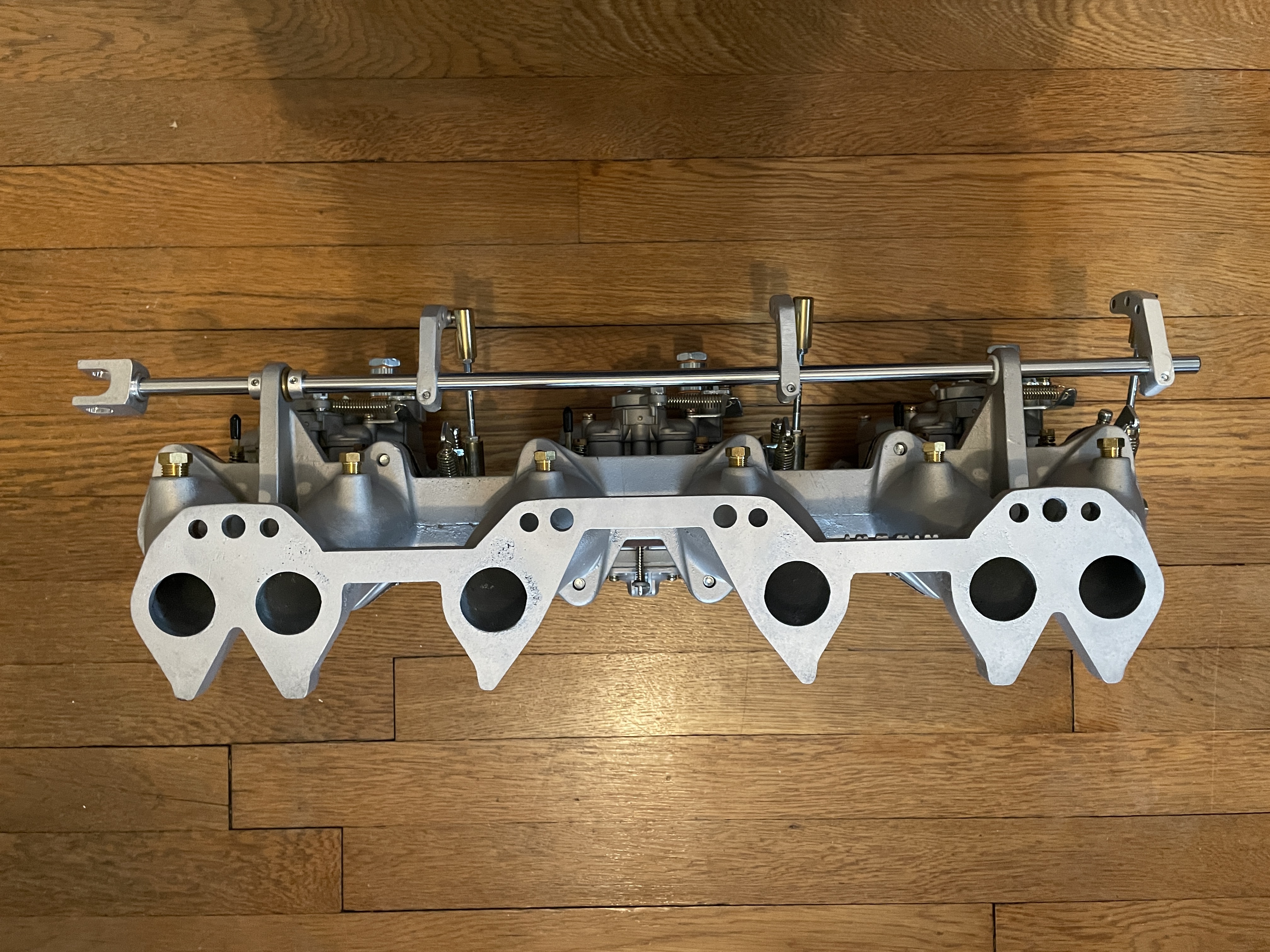
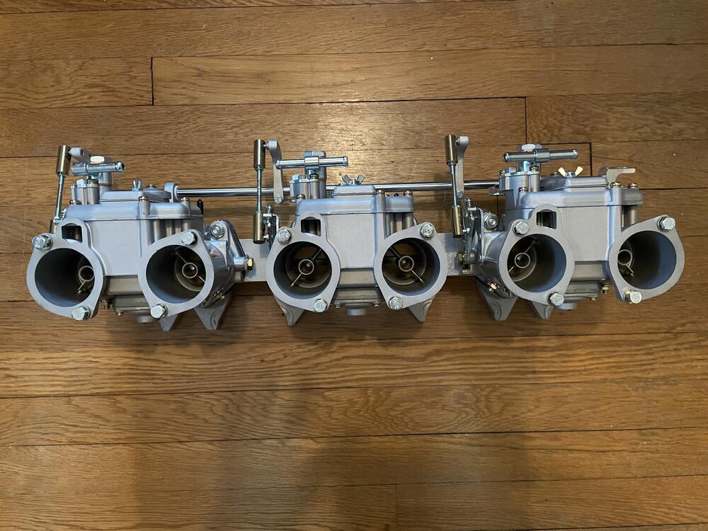
New treasure! 3 Mikuni 44 PHHs. I bought these on Yahoo! Japan back in December. Jesse Streeter helped me get them Stateside and I had them rebuilt by Taka at Kyushu House, who moved to Houston in the middle of the rebuild, hence the delay. They look fantastic. The manifold also looks pretty good considering it was pretty beet up when I bought it. It had no linkage and needed to be vapor blasted, but there are very few imperfections. Just some putting on the surface that mates to the header gasket. Can’t wait to get them running.


-
I’m going to start with the body harness and see what the impact of the larger outer diameter looks like. If it’s overwhelming I’ll figure something else out for the dashboard. The body and engine have the room to handle it, but the dashboard may have trouble.
-
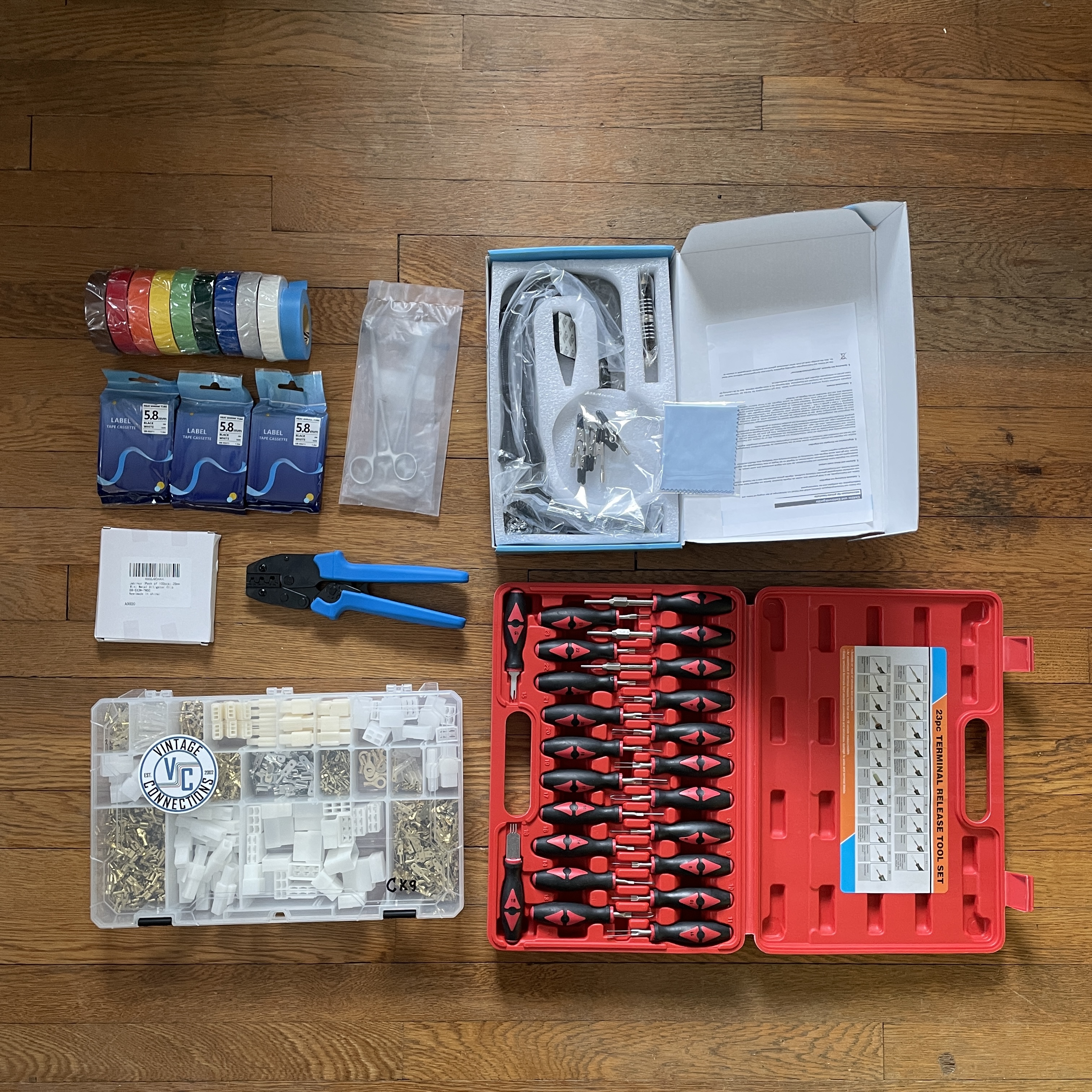
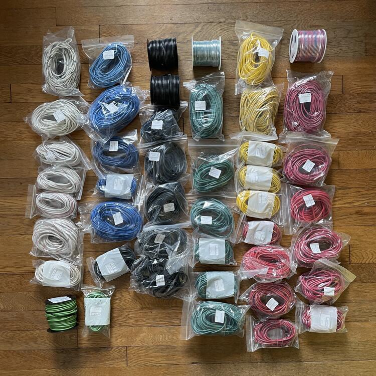
Here we go! Nearly 2,000 feet of wire (a surprisingly large number for such a simple and small car), connectors, tape, and the various tools that I didn’t already have for assembling the various wiring harnesses. The wire is the marine grade from Sherco Auto and Marine Supply that @SteveJ referenced at the beginning of this thread. They did a good job with the order, but I’m a little bummed about the inconsistency of the wire color, in particularly the tracer stripes. I also did not take into account the increased outer dimensions of marine grade wire. The gauge is the same, but the insulation is pretty thick. I might run into some issues when I try to lace the looms through some openings or around corners. We shall see… 🤞🏻 The connectors are the Vintage Connectors 240z kit. I will let you know how accurate it is to a 1973 setup. There will be obvious differences where the three main harnesses meet due to the lack of the colored 10-pin connectors. The tools are just Amazon specials from china. I didn’t see a need to go pro on this because I hope to never do it again. Here's the inventory of wire: Wire Gauge Wire Color Needed Link Length Price QTY Total 10 AWG Black 22 10 Gauge Black Marine Tinned Copper Primary Wire - 25 FT 25 $22.90 1 $22.90 Red w/ White 8 Primary Tracer Marine Tinned Copper 10 Gauge AWG x 25 FT Coil - Red Wire & White Striped - USA 25 $23.56 1 $23.56 White 8 10 Gauge White Marine Tinned Copper Primary Wire - 25 FTl 25 $22.90 1 $22.90 White w/ Red 20 Primary Tracer Marine Tinned Copper 10 Gauge x 25 FT Coil - White Wire & Red Stripe - USA 25 $23.56 1 $23.56 Sub-Total 58 100 4 $92.92 12 AWG Black 15 12 Gauge Black Marine Tinned Copper Primary Wire - 25 FT 25 $14.85 1 $14.85 Black w/ White 16 Primary Tracer Marine Tinned Copper 12 Gauge x 25 FT Coil - Black Wire & White Stripe - USA 25 $16.56 1 $16.56 Black w/ Yellow 22 Primary Tracer Marine Tinned Copper 12 Gauge x 25 FT Coil - Black Wire & Yellow Stripe - USA 25 $16.56 1 $16.56 Blue 4 12 Gauge Blue Marine Tinned Copper Primary Wire - 25 FT 25 $14.85 1 $14.85 Green 17 12 Gauge Green Marine Tinned Copper Primary Wire - 25 FT 25 $14.85 1 $14.85 Green w/ White 4 Primary Tracer Marine Tinned Copper 12 Gauge AWG x 25 FT Coil - Green Wire & White Striped - USA 25 $16.56 1 $16.56 Red 23 12 Gauge Red Marine Tinned Copper Primary Wire - 25 FT 25 $14.85 1 $14.85 Red w/ Black 21 Primary Tracer Marine Tinned Copper 12 Gauge AWG x 25 FT Coil - Red Wire & Black Striped - USA 25 $16.56 1 $16.56 Red w/ White X Primary Tracer Marine Tinned Copper 12 Gauge x 25 FT Coil - Red Wire & White Stripe - USA 25 $16.56 1 $16.56 Red w/ Yellow 11 Primary Tracer Marine Tinned Copper 12 Gauge x 25 FT Coil - Red Wire & Yellow Stripe - USA 25 $16.56 1 $16.56 White 5 12 Gauge White Marine Tinned Copper Primary Wire - 25 FT 25 $14.85 1 $14.85 White w/ Red 9 Primary Tracer Marine Tinned Copper 12 Gauge x 25 FT Coil - White Wire & Red Stripe - USA 25 $16.56 1 $16.56 Yellow 7 12 Gauge Yellow Marine Tinned Copper Primary Wire - 25 FT 25 $14.85 1 $14.85 Sub-Total 154 325 13 $205.02 14 AWG Black 161 14 Gauge Black Marine Tinned Copper Primary Wire - 100 FT 100 $37.71 2 $75.42 Black w/ White 42 Primary Tracer Marine Tinned Copper 14 Gauge x 25 FT Coil - Black Wire & White Stripe - USA 25 $10.44 2 $20.88 Black w/ Yellow 30 Primary Tracer Marine Tinned Copper 14 Gauge x 25 FT Coil - Black Wire & Yellow Stripe - USA 25 $10.44 2 $20.88 Blue 28 14 Gauge Blue Marine Tinned Copper Primary Wire - 25 FT 25 $9.93 2 $19.86 Blue w/ Red 56 Primary Tracer Marine Tinned Copper 14 Gauge x 25 FT Coil - Blue Wire & Red Stripe - USA 25 $9.93 3 $29.79 Blue w/ White 57 Primary Tracer Marine Tinned Copper 14 Gauge x 25 FT Coil - Blue Wire & White Stripe - USA 25 $10.44 3 $31.32 Blue w/ Yellow 10 Primary Tracer Marine Tinned Copper 14 Gauge x 25 FT Coil - Blue Wire & Yellow Stripe - USA 25 $10.44 1 $10.44 Green 112 14 Gauge Green Marine Tinned Copper Primary Wire - 100 FT 100 $37.71 1 $37.71 14 Gauge Green Marine Tinned Copper Primary Wire - 25 FT 25 $9.93 1 $9.93 Green w/ Black 57 Primary Tracer Marine Tinned Copper 14 Gauge x 25 FT Coil - Green Wire & Black Stripe - USA 25 $10.44 3 $31.32 Green w/ Blue 21 Primary Tracer Marine Tinned Copper 14 Gauge AWG x 25 FT Coil - Green Wire & Blue Striped - USA 25 $10.44 1 $10.44 Green w/ Red 52 Primary Tracer Marine Tinned Copper 14 Gauge x 25 FT Coil - Green Wire & Red Stripe - USA 25 $10.44 3 $31.32 Green w/ White 65 Primary Tracer Marine Tinned Copper 14 Gauge x 25 FT Coil - Green Wire & White Stripe - USA 25 $10.44 3 $31.32 Green w/ Yellow 15 Primary Tracer Marine Tinned Copper 14 Gauge x 25 FT Coil - Green Wire & Yellow Stripe - USA 25 $10.44 1 $10.44 Red 32 14 Gauge Red Marine Tinned Copper Primary Wire - 25 FT 25 $9.93 2 $19.86 Red w/ Black 54 Primary Tracer Marine Tinned Copper 14 Gauge x 25 FT Coil - Red Wire & Black Stripe - USA 25 $10.44 3 $31.32 Red w/ Blue 90 Primary Tracer Marine Tinned Copper 14 Gauge x 100 FT Spool - Red Wire & Blue Stripe - USA 100 $37.58 1 $37.58 Red w/ Green 2 Primary Tracer Marine Tinned Copper 14 Gauge x 25 FT Coil - Red Wire & Green Stripe - USA 25 $10.44 1 $10.44 Red w/ White 3 Primary Tracer Marine Tinned Copper 14 Gauge x 25 FT Coil - Red Wire & White Stripe - USA 25 $10.44 1 $10.44 Red w/ Yellow 8 Primary Tracer Marine Tinned Copper 14 Gauge x 25 FT Coil - Red Wire & Yellow Stripe - USA 25 $10.44 1 $10.44 White 36 14 Gauge White Marine Tinned Copper Primary Wire - 25 FT 25 $9.93 2 $19.86 White w/ Black 66 Primary Tracer Marine Tinned Copper 14 Gauge x 25 FT Coil - White Wire & Black Stripe - USA 25 $10.44 3 $31.32 White w/ Red 4 Primary Tracer Marine Tinned Copper 14 Gauge x 25 FT Coil - White Wire & Red Stripe - USA 25 $10.44 1 $10.44 Yellow 35 14 Gauge Yellow Marine Tinned Copper Primary Wire - 25 FT 25 $9.93 2 $19.86 Yellow w/ Black 17 Primary Tracer Marine Tinned Copper 14 Gauge AWG x 25 FT Coil - Yellow Wire & Black Striped - USA 25 $10.44 1 $10.44 Yellow w/ Blue 28 Primary Tracer Marine Tinned Copper 14 Gauge x 25 FT Coil - Yellow Wire & Blue Stripe - USA 25 $10.44 2 $20.88 Yellow w/ White 17 Primary Tracer Marine Tinned Copper 14 Gauge x 25 FT Coil - Yellow Wire & White Stripe - USA 25 $10.44 1 $10.44 Sub-Total 1098 900 49 $614.39 Total 1325 66 $912.33

-
After a long hiatus due to the layoff apocalypse in the tech industry I’m back on this. I just purchase the 240z kit from Vintage Connections. It’s not exactly right for a ‘73 240z but it’s close and I can probably use the extra bits for my electric fans and the like. I’m going to have to reuse my colored connectors that join the harnesses to each other, since those are NLA. As for the wire itself, I’m going to take @SteveJ’s advice and go with the marine-grade striped wire from Sherco. It’s a step up from the standard automotive wire I had been looking at, plus I can stick to the factory wire color combinations. I’m mostly done with the modifications to my wiring diagram, with the exception of the changes to the tail lights I mentioned previously and the third brake light, as well as the 12-volt socket to replace the cigar lighter and the USB-C plugs I want to add. Should be simple. Oh, and I realized that I had been making the volt meter modification too complicated. If I retain the ammeter wiring and splice in a thin wire for the volt meter I’ll have the perfect setup for a kill switch. I will I se that switch to join the white and white / red wires (rather than splicing them) and relocate all of that down to the lower part of the dash or center console to mount the switch. Easy Peezy, in theory.
-
I can’t because I bought it from Z Car Depot.
-
Finished drawing up the wiring change for the tail lights:

-
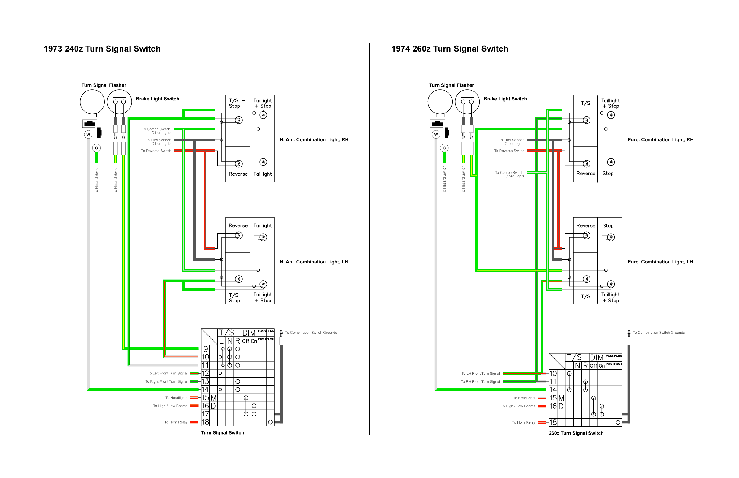
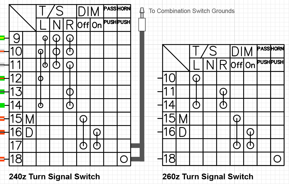
Thanks for the tips @billgtp! I will file this away for later. Right now I am working on switching out the 240z turn signal switch in my diagram for one from a 260z. This mod will also involve changing the rail lights to the euro configuration. Here's the main guide I am looking at. I will be doing the same thing as the guide I am using for reference by creating an interim harness that adapts the 260z switch to the 240z dash harness. My first issue is that I made a few errors in my first diagram where I had the front turn signals going to the pin for the rear signals, and vice versa. That has been fixed. My second issue is that the tail lights all ground to the fuel tank sending unit. I need to go back to the harnesses and make sure that is correct. A quick look at the FSM tells me it is, but I am not 100% certain, given the number of other errors I found in that thing. As noted in the guide above, the 260z does not send the brake signal through the turn signal switch, so I have to figure out how that is supposed to be wired in those cars. The rest of it seems pretty straight forward, though. Here's a diagram of the two switches: In the 240z, #9 is the signal coming from the brake switch. In the 260z, the #9 is in neither the combo switch (wiper switch) nor the TS switch, so I am looking at where it goes. #10 through #14 are consolidated in the 260z. Another thing I noticed is that the tail light harnesses I got from Z Car Depot each has a socket for a dual-filament bulb where the red wire is cut and knotted. These are brand new, so I need to look into what that is for. Once I find my old ones I should be able to make a comparison and see what is up. Its a little bit of a pain because the wires switch colors underneath the wrap and have no relationship to the FSM. Fun times. *** I know it seems like I am jumping around, but I'm finding that these different sections impact each other in that I have to route wires for the new components through the colored connectors at the bulkhead, so I think it is better that I resolve all of the swaps before I resolve the additions.

-
Thanks. I've dug through everything and it looks like I am good to go with this voltmeter. *** I've started working on adapting my Vintage Air Gen II Mini air conditioner to the dash harnesses. One thing I just noticed today is they have two wires coming into it from the car: one from the battery (30 amps) and one from the ignition (5 amps). Both of these go to a relay that goes to the fan switch and a second relay that feeds the blower on the evaporator. https://www.vintageair.com/instructions_pdf/MINI GEN II HCD WIRING DIAGRAM.pdf I am wondering if I need this relay because I have the power coming off the accessory relay, which is on the ignition switch already. In theory I could just remove the relay Vintage Air has in their wiring and connect it into the power that used to feed the heater blower. It just feels like an extra relay that isn't needed. Or am I missing something and I need a separate wire from the ignition that isn't going through the accessory relay? Thoughts?
-
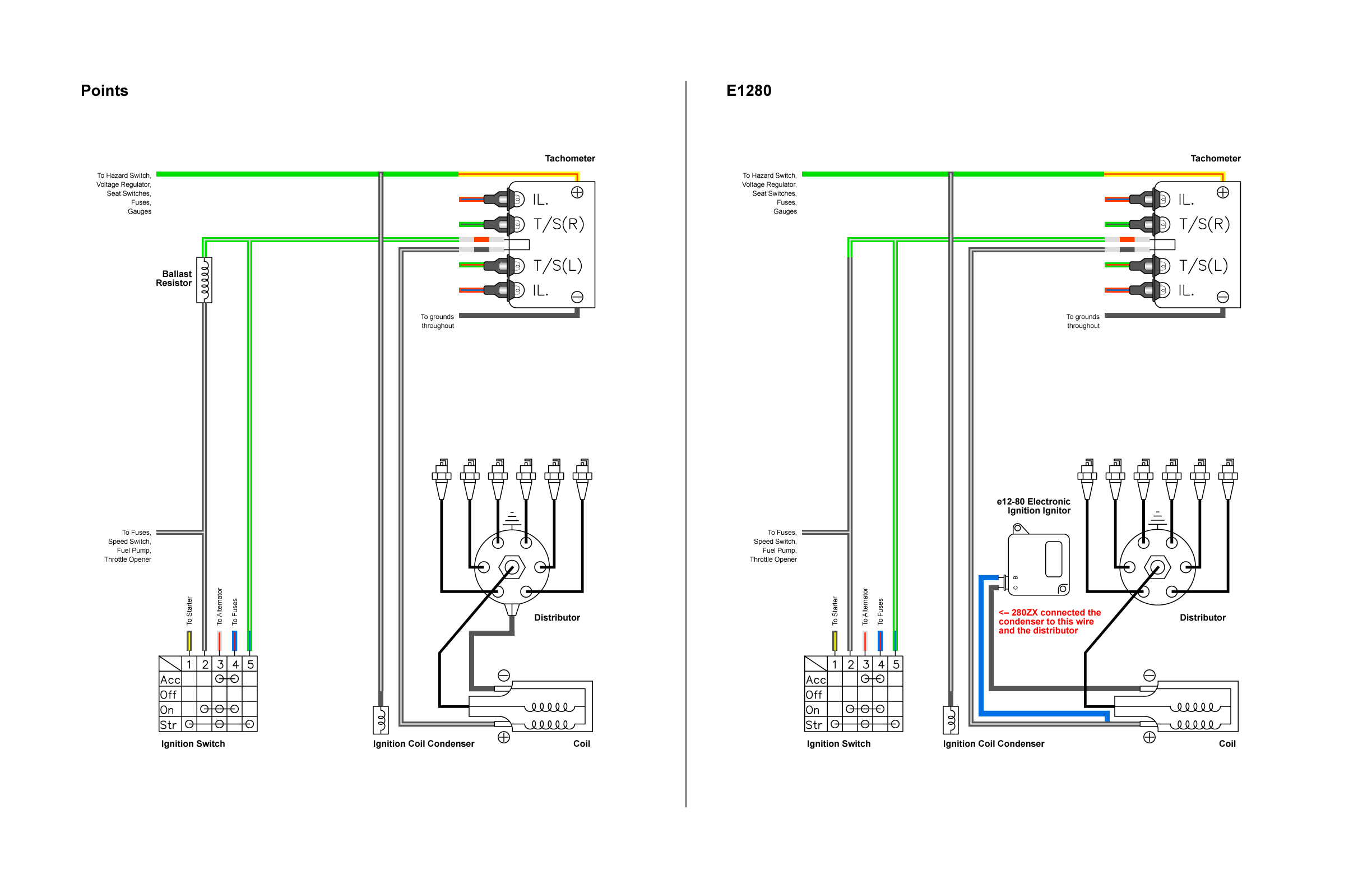
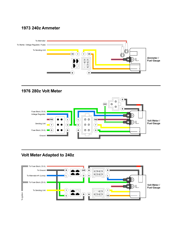
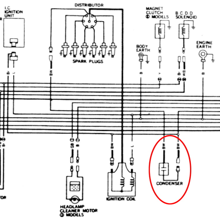
I've been working on some detail illustrations for the individual component modifications that I am making to these harnesses. First up are the ignition and the volt meter. I have been able to find good documentation, including diagrams of the wiring, of how these two modifications are supposed to be done, so I was able to consolidate all of that and add some details based on the work I have been doing in the harness diagrams. 240z e12-80 Ignition & Distributor Wiring Modification: This ignition setup is pretty straight forward and has been documented repeatedly in several places, but I have found some details about how the 280zx distributor is set up in its factory setup in a 1979 ZX, specifically the condenser. There are tons of components that tie into the wires that connect to the ignition that simply don't exist in the 1970-78 cars. I am guessing (since people have been able to make this setup work in Z cars) this doesn't impact anything, but it does make me take a pause when I am trying to be thorough and have a clean harness when I am finished. I plan to dig into this a little deeper, but I have reassurance from a couple people in this thread and my main build thread that this setup works without requiring any other mods, such as the 280z tachometer swap and/or adding a 2.2k ohm resistor or a MSA HI-6 box. 240z Volt Meter Wiring Modification: The volt meter I have is from a 1976 280z. I chose this one because the face is closest to the 1973 ammeter as far as the typography and graphics are concerned. It's not a match, but it's close enough that it looks like it could have been in the car original. The 1977-8 volt meter has completely different lettering and looks like a mistake. I'm relying heavily on the information @tamo3 and @EuroDat posted in this thread where @tamo3 showed how he modified a 1977 voltmeter to fit into a 1975 280z. It's pretty clear, but I am planning to modify it further because the 1973 combination switch doesn't connect to the ammeter like it does in the 1975. The only hesitation I have on how I have drawn this up is the illumination light. In the 240z you have a single wire light that grounds to the instrument case. in the 280z you have the 2-wire lights that connect directly the common ground throughout the wiring. I am pretty sure but not 100% sure this will still work because the case is grounded via the black wire on the 4-pin connector that goes to the fuel pump.


-
Thanks! I was just looking at that. I also found one for a Nissan Juke I am considering. The overlanding / off-roading community seems that have a bunch of stuff in this space. Must be for all those light bars.
-
Made a little bit of progress yesterday on my electric fan set up. The main "Ah ha!" moment that I had one I can simplify things by adding an auxiliary fuse box. I know adding an additional component sound like making this more complex, not simpler, but what I realized is that all of my new components in the engine bay could be fed off that Aux fuse box. The only two things I am adding up front are the air conditioning system and the electric radiator fans, which means the wiring from the engine harness to that fuse box can be pretty simple. Components for the electric radiator fan are: 1 x Fan thermostat switch (I am looking into using the two-wire 280ZX switch at the water neck for this) 2 x Fan Relay 2 x Circuit Breaker 2 x Electric Fan Components under the hood for the air conditioning are: Air Compressor AC Trinary Switch (automatically shuts off the air-conditioning clutch if the refrigerant pressure gets too high / low) A/C Compressor Low Idle Control Idle Adjustment Solenoid The thing I am trying to figure out now is if the AC components should be wired to the Accessory position on the key, or if they can be on the On position. The fans will be on the On position. It's not a big deal either way, but I want to talk to Vintage Air about it tomorrow to see what they say about it. The evaporator and thermostat switch in the dash are both already on the Accessory position. Now to find a fuse box.
-
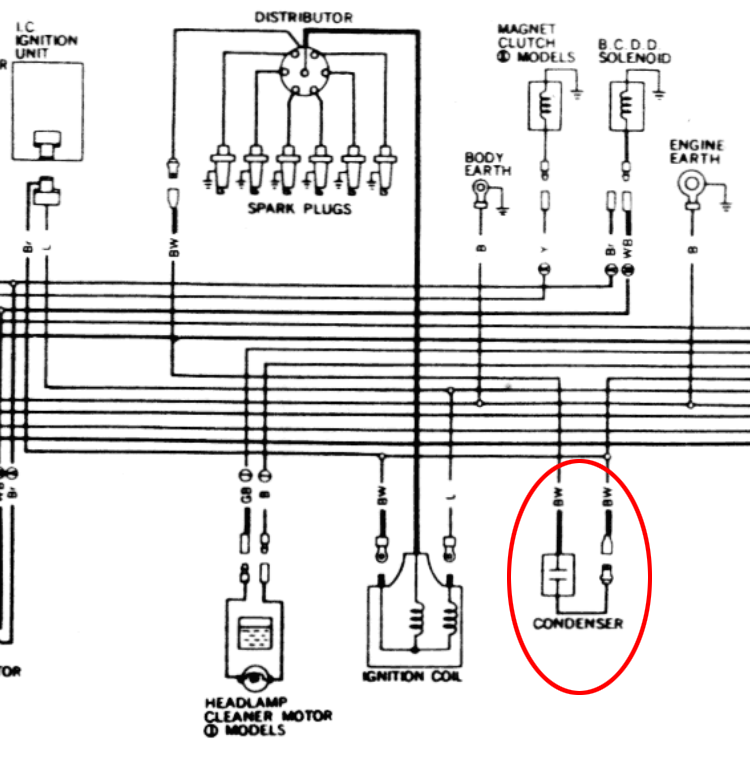
The ZX had two as well, even though it didn't have points; one on the alternator and an RF interference condenser on the distributor. It didn't connect to the coil but it did connect to the ignition switch.
-
Thanks. I will read up on them. As I am working in integrating my ZX distributor into my wiring, I noticed quite a few threads here and over at Hybridz where people say you can live without the condenser that is NLA for those cars. This was the 2-wire condenser that plugged into a wire coming out of the distributor on one end and spliced into the BW wire going to the electronic ignition on the other. I'm also noticing that in the ZX the condenser joins up to wires going to the fuel pump and the ignition switch, whereas the 240z has the condenser on a wire that goes to the seat switches, fuse box, hazard switch and some gauges. Curious if anyone has any thoughts on this. Right now I am leaning toward keeping the 240z setup for that specific component.
-
Fun story: I have been looking at the diagram of how to wire up a 280ZX distributor and couldn't for the life of me figure out why my BW wires didn't match the diagram. I chased the wires in my harnesses from the coil to the ignition and the tach and back again about six times, drew up how my wires are routed vs the FSM, and was about freak out before I realized that the wires for the ballast resistor and the coil have the same plugs and I just had them labeled wrong. I swapped the labels on my harness and now everything makes sense. Derp. Are you going to run the original alternator (or one from a 280zx)? Mine is the GM-style. Part of me wishes I had gone with a newer Nissan alternator instead, but I bought it back when I first bought the car and wasn't really thinking about this stuff then. I'm going to take a look at how your configuration would look in my situation, but relays are a subject I need to read up on before I can confidently mess with them.
-
So the ignition controls the relay and that relay sends the constant voltage to the Alternator, or do you mean having a constant voltage source separate from the relay? What I am reading says not to have a constant voltage source to the L terminal that is not controlled by the switch. I think maybe you mean having the relay controlled by the switch, but I want to make sure we are saying the same thing. Ah, right. Good point. The more I work on this the less convinced I am that I should change the dash lights to LEDs, but that one would be outside of the rheostat circuit so maybe it doesn't impact that choice.
-
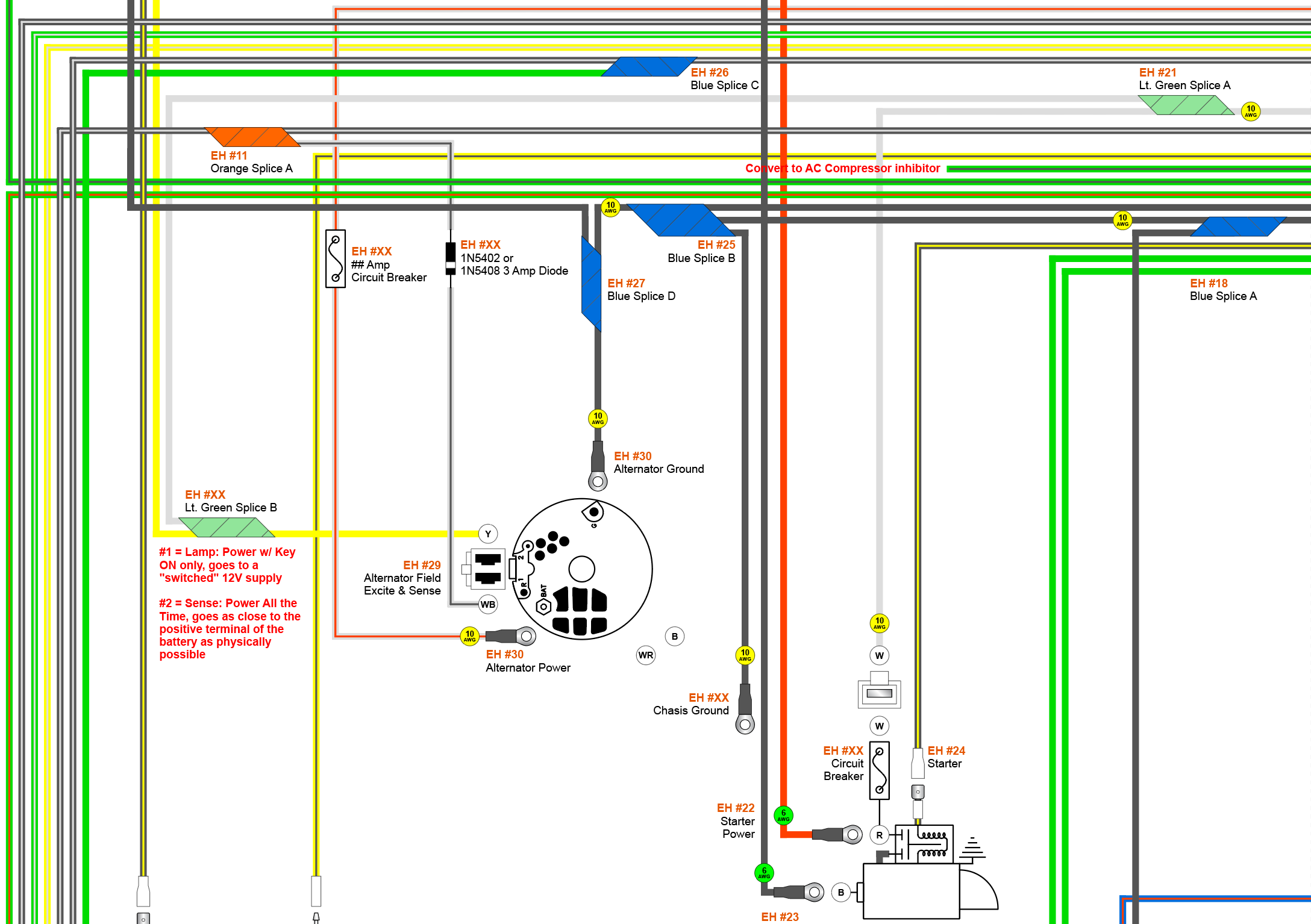
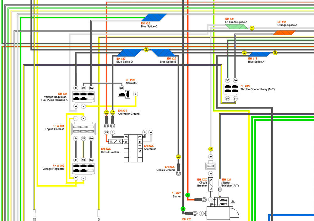
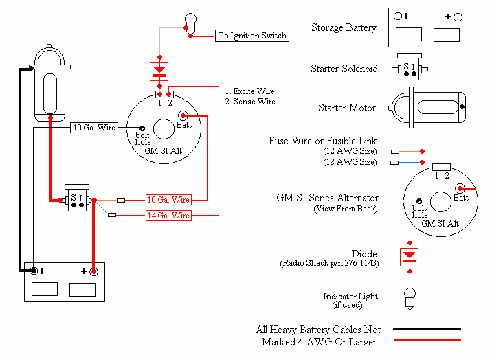
I've been working on getting the correct wiring for my internally regulated 100-amp alternator into the diagram and have run into some interesting things while digging around. I think I have it pretty close, but I'm interested to see if anyone has any comments or alternative suggestions. The reference material I have been looking at is mostly @bvolken's article on installing a 280ZX alternator, a general guide to installing 100-amp alternators in Z cars from the Edmonton Z Car Club, and random stuff about correctly wiring the GM alternator into other cars. So, when looking at the wiring for the OEM alternator, this is what we start with: I could just take all that out and go with a single wire setup, but I am opting for using the excite and sense wires for reasons outlined in the Edmonton article already mentioned. So based on what I have learned about this system so far, this is what I have: A few things to note… 1. The combination of the voltage regulator and Fuel Pump Harness A (24032-N3300) created what amounted to a splice between the white wire coming off the engine harness and the yellow wire going to the fuel pump relay. I am preserving that here with a splice wrapped in light green tape. This will also supply a "Sense" wire for the alternator (terminal 2). I have read that it is better to have the "sense" wire come from something closer to the circuits for the accessories than directly from the battery, so I think repurposing / updating @bvolken's alternator wire rewire option gets me there. However, I am running my excite wire off the wire from the coil because it goes directly to the "on" position on the ignition, rather than using the BW/WB wires that originally went to the voltage regulator. Here's an example of the direct wiring approach for reference: 2. I have retained the orange splice on the black wire with a white stripe that goes to the coil positive post from the "ON" position on the ignition switch, but now that wire is going to the "Lamp" or "Excite" wire for the alternator (terminal 1). 3. I have a 3-amp diode in the diagram, but I am uncertain about this addition. I will also be swapping my Ammeter out for a Voltmeter from a 260z, and those have the small red "Charge" light which sort of functions in a similar way by providing resistance until the alternator comes up to full speed. @SteveJ, I am curious about your opinion on this. Does having the diode AND the light create too much resistance, or can I get away with both? Otherwise this isn't substantially different from the original circuits. You may have also noticed that I have deleted the seatbelt relay and the throttle opener relay. I think I have this done correctly but need to triple check it. I might be adding a 120-amp circuit breaker on the red cable coming off the battery for extra extra extra protection, but I will definitely be replacing the fusible link on the starter with a resettable circuit breaker.

-
Okay, I need to move on to the next step and stop swirling on this diagram. Here it is in all of it's glory. I am pretty sure it is correct throughout but if anyone sees any errors, please let me know. It should be much more helpful for anyone with a 1973 than the ones previously posted since it is comprehensive and verified. 1973-240Z-Wiring-Diagram-Draft.pdf So the next step is to make the changes that I intend to have in the car. Here's the list: 1. Convert to 280ZX distributor & E12-80 Ignition * Delete Ballast Resistor * Add ZX RF Resistor * Investigate and Update Condensers * Mimic 1979 280ZX wiring * Investigate 240z vs 280z tach issues more thoroughly 2. Change Alternator to Single Wire * Delete Voltage Regulator * Maintain Fuel Pump Wiring 3. Replace Heater Blower with AC * Delete Heater Blower Harness * Maintain Illumination for Controls * Add necessary AC Components * Add Wide Open Throttle Switch * Add Fan Temp Switch * Add Electric Fan Relay * Add Electric Fan * Add AC Thermostat Switch (mimic 1979 280ZX wiring) * Add AC Trinary Switch * Air Compressor * Add Air Conditioning Evaporator * Replace Throttle Opener with Fast Idle Control Device * Delete Throttle Opener Relay (refer to 1972 Wiring) * Remove Throttle Opener Solenoid * Investigate FICD Wiring 4. Replace Ammeter with Volt Meter 5. Change to Euro brake / signal configuration * Replace 240z turn signal switch with 260z turn signal switch * Update wiring at Combination Lights * Add 3rd Brake Light 6. Replace Cigar Lighter with 12-volt socket 7. Update Dashboard to LEDs * Investigate Dimmable LED bulbs * Investigate LED Dimmer to replace Rheostat 8. Consider Replacing Radio Wiring with Bluetooth Controls and Charging feeds * Investigate Bluetooth Controls * Investigate GPS Units * Investigate Backup Cameras 9. Add USB-C Wiring for charging 10. Determine if I need, and then find, new relays