Matthew Abate
-
Posts
1,187 -
Joined
-
Last visited
-
Days Won
16
Content Type
Profiles
Knowledge Base
Zcar Wiki
Forums
Gallery
Events
Downloads
Store
Blogs
Collections
Classifieds
Everything posted by Matthew Abate
-
It’s alive… sort of. I’ve been making little tweaks to try to get base timing dialed in, but there’s a lot out of whack right now and it’s a slow process. Today I checked the float levels, which were all at 12mm, set the idle speed adjustment screws and idle mixture/pilot screws to 1.5 turns, and primed the float chambers. After tweaking the throttle screws a bit it is starting pretty easily, but it’s rough as hell and the timing is out of whack (26 to 40° at various points). The fuel pressure is also too high because I had to pull my return lines off. They were starving the carbs the way I had them, so I’m going to have to rethink how I route that. I guess I know what I’m doing this week.

-
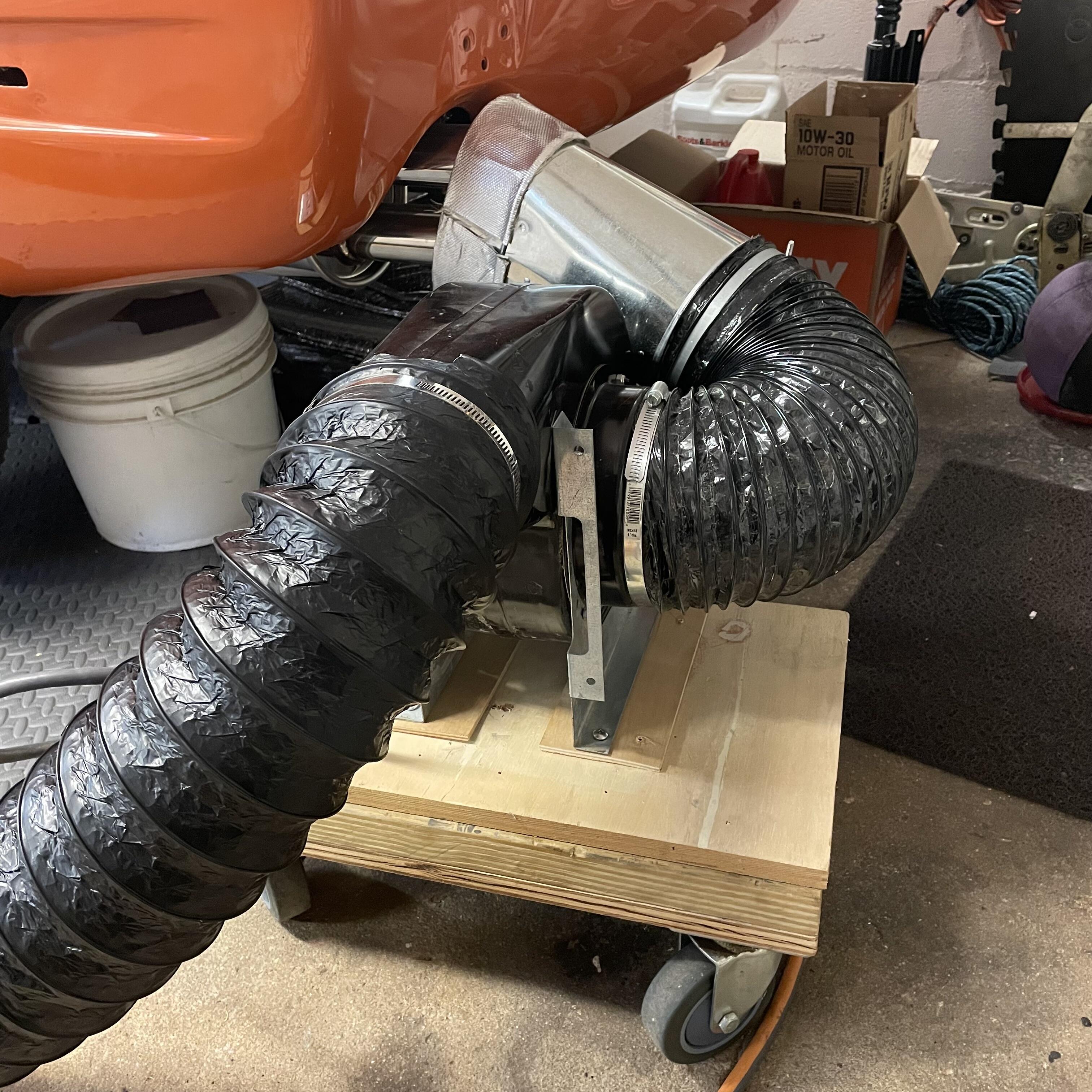
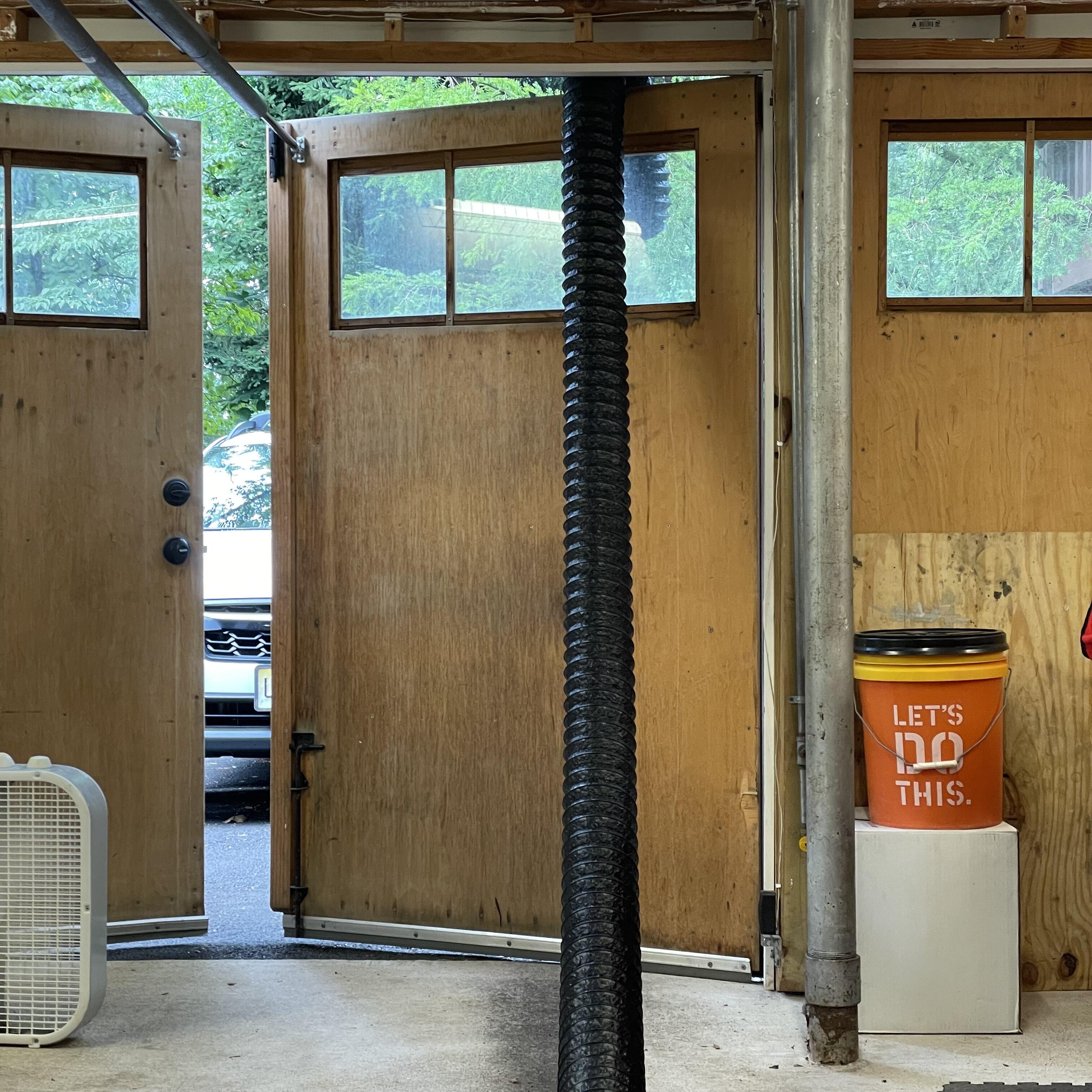
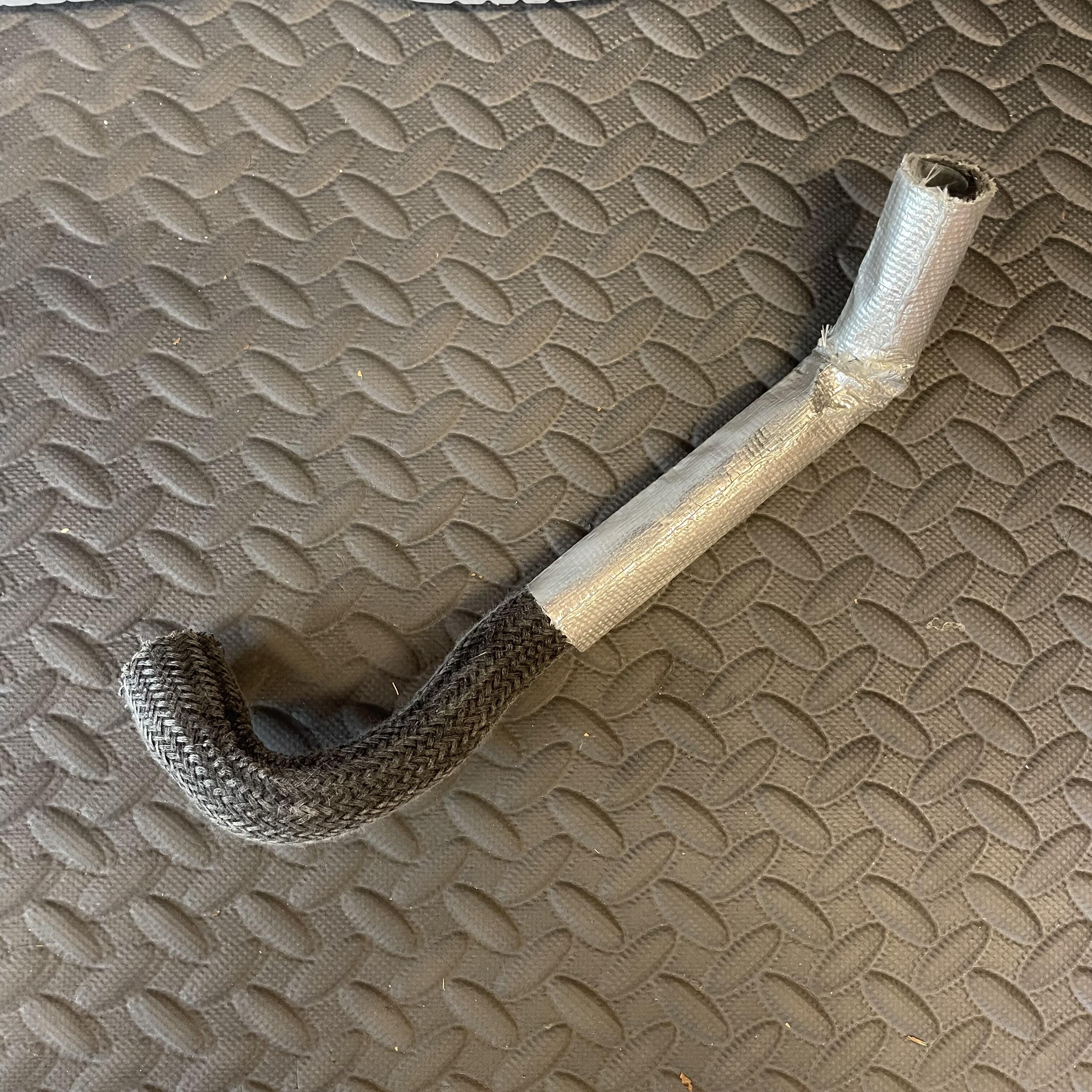
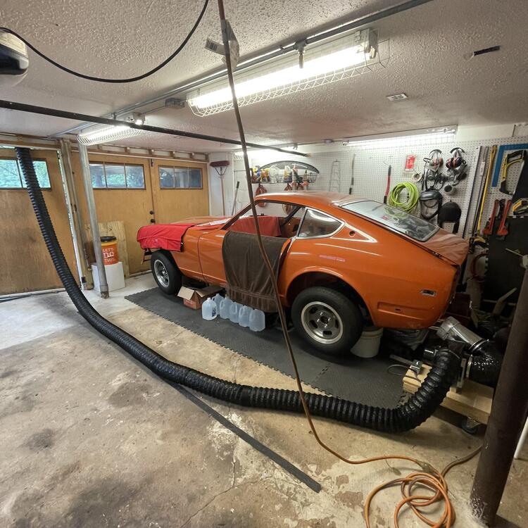
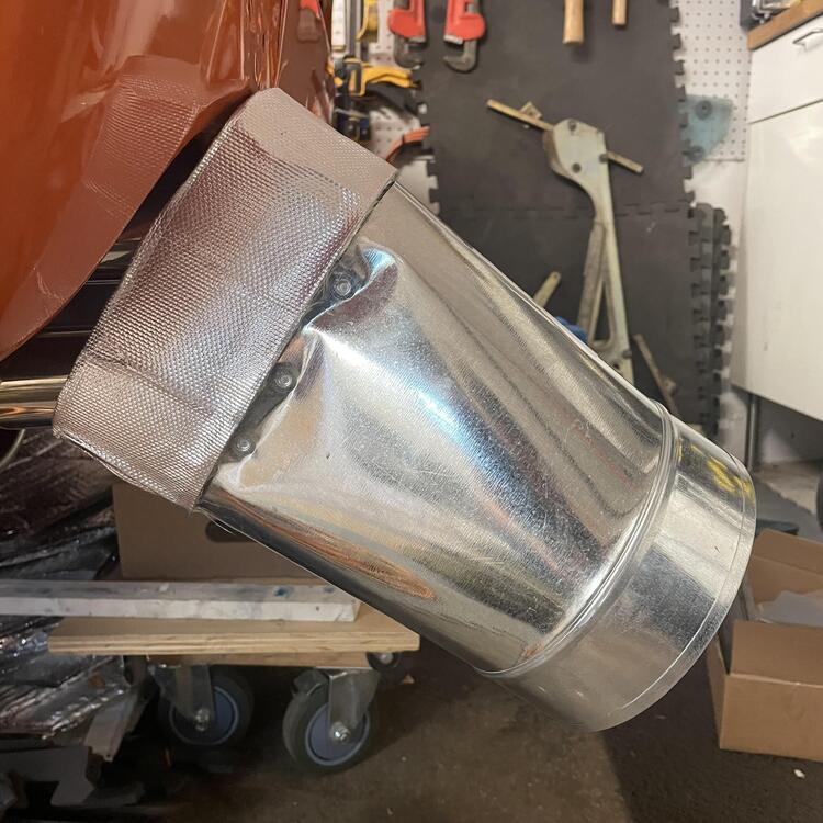
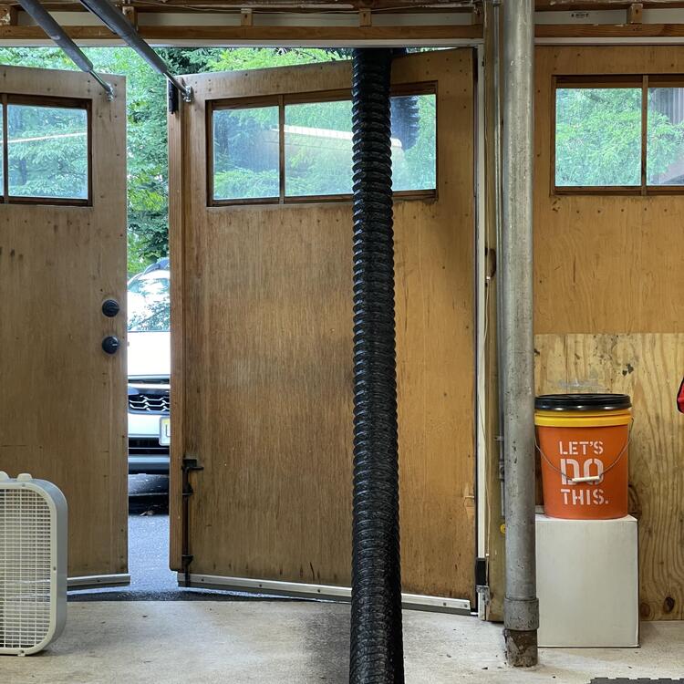
I made myself a little exhaust evacuation system so I can keep the car backed into the garage without gassing up my whole house. My in-laws recently refurbished their oven so they had a blower from an oven hood laying around. A piece of HVAC ducting with some scrap heat shield and some hose did the job. I do wish the fan in this thing was stronger, but if it’s not doing enough I’ll supplement it with a Vornado house fan under the back of the car blowing toward the front. 🤞🏻

-
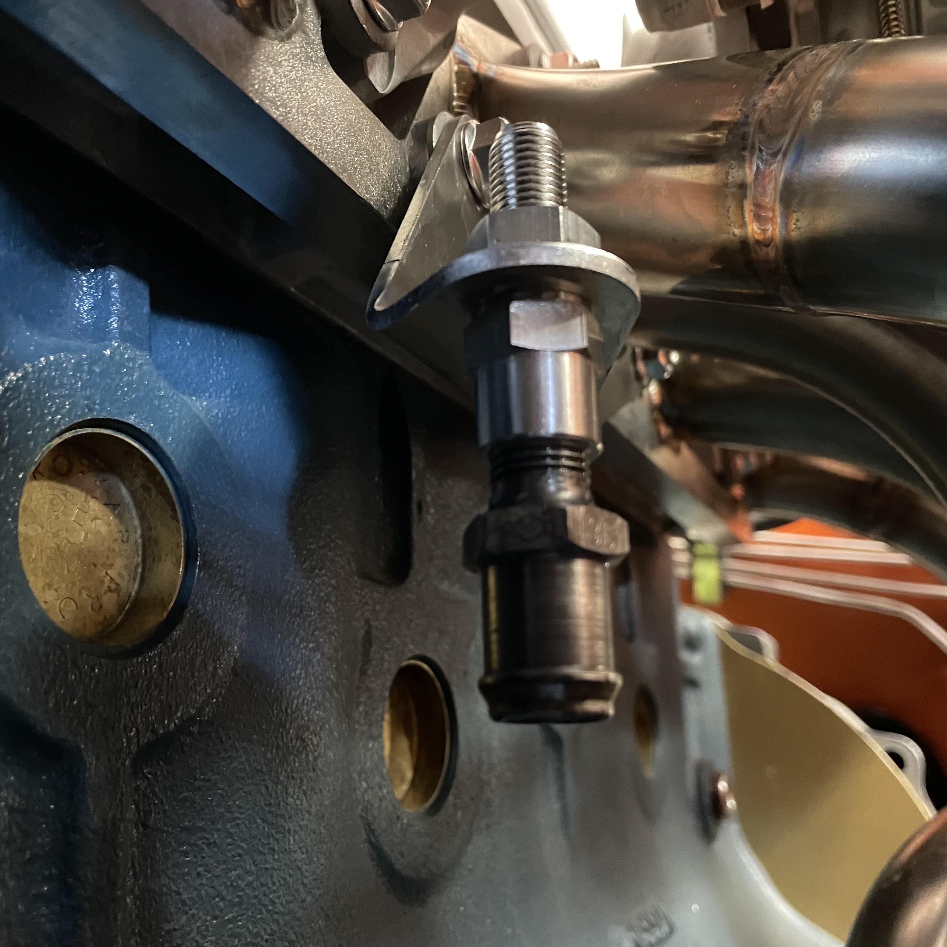
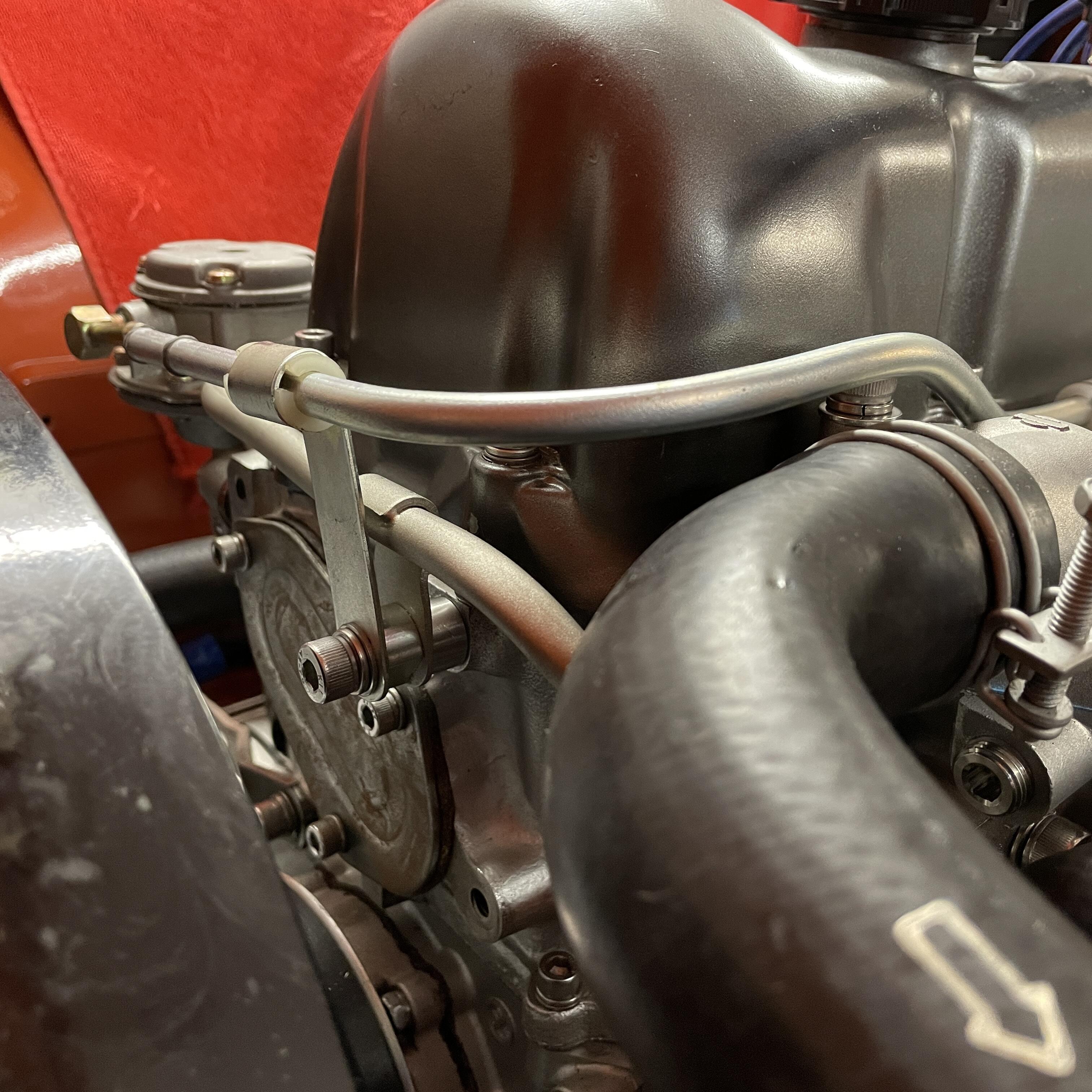
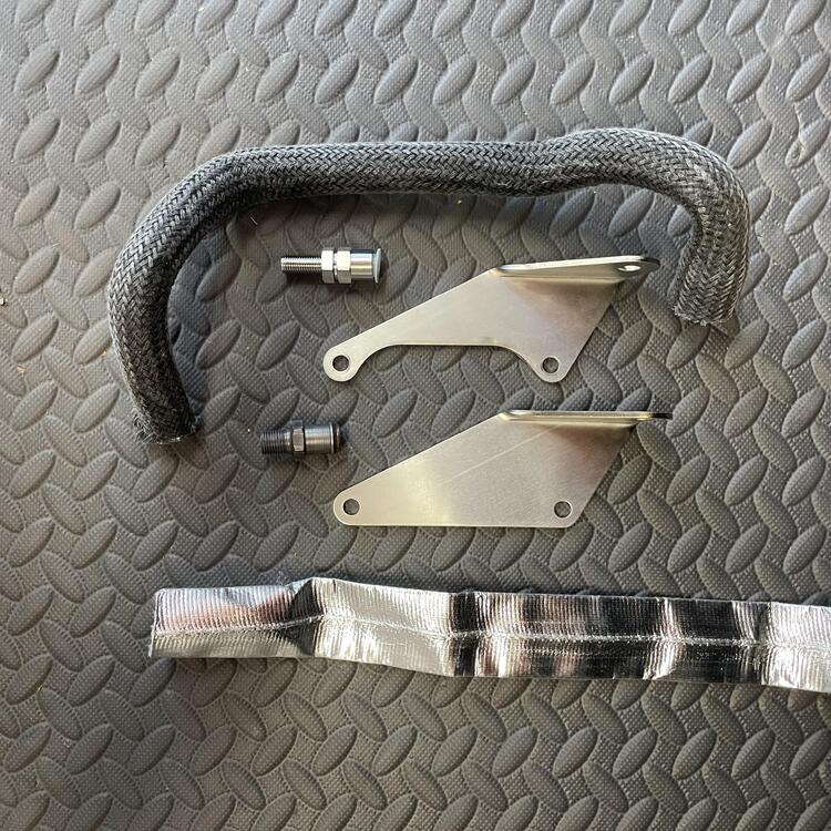
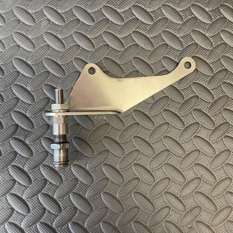
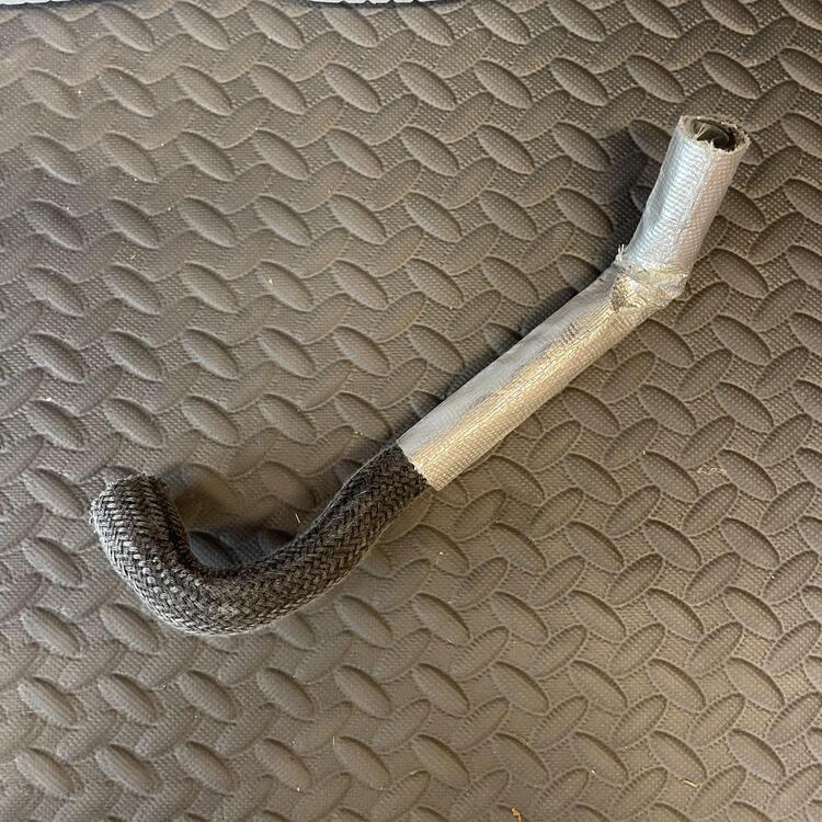
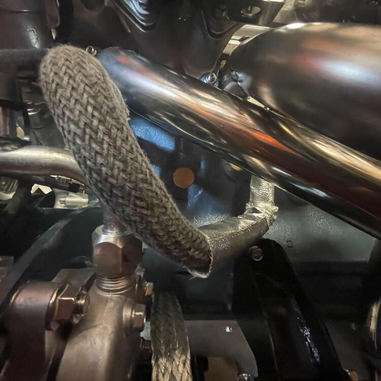
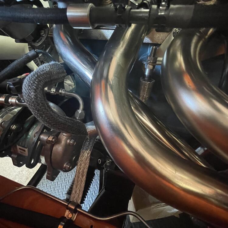
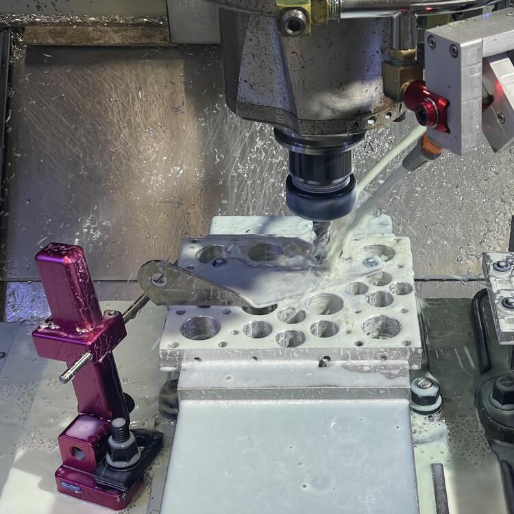
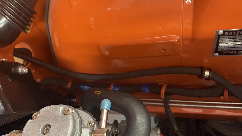
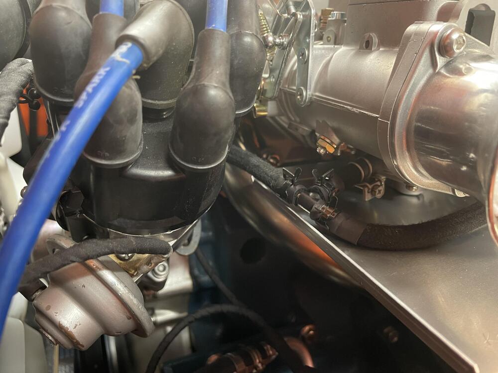
More harebrained schemes! With the change from SUs to PHH 44s I lost the balance tube from the Nissan manifold, which is where the PCV valve went. I’m not content to throw my hands up and say “Oh well” on all of the compromises these carburetors usually cause, so I made a bracket. Or rather, SendCutSend made me a bracket. It came out great, but I forgot to provide clearance for the 3 and 4 cylinder exhaust pipes on the manifold, so a friend graciously did a little CNC work on it for me. I’m reasonably confident this will be a good relocation point for the valve. The tricky part from here is going to be plumbing it into the intake manifold. The fitting the valve is screwed into is a Fuji 1/4” BPST to 1/4” OD compression bulkhead union. I was only able to find one place who would sell me just one, but @misumiusa was quick with it. I’m planning to run a stainless steel pipe to a vacuum manifold that will then route to the intake manifold.

-
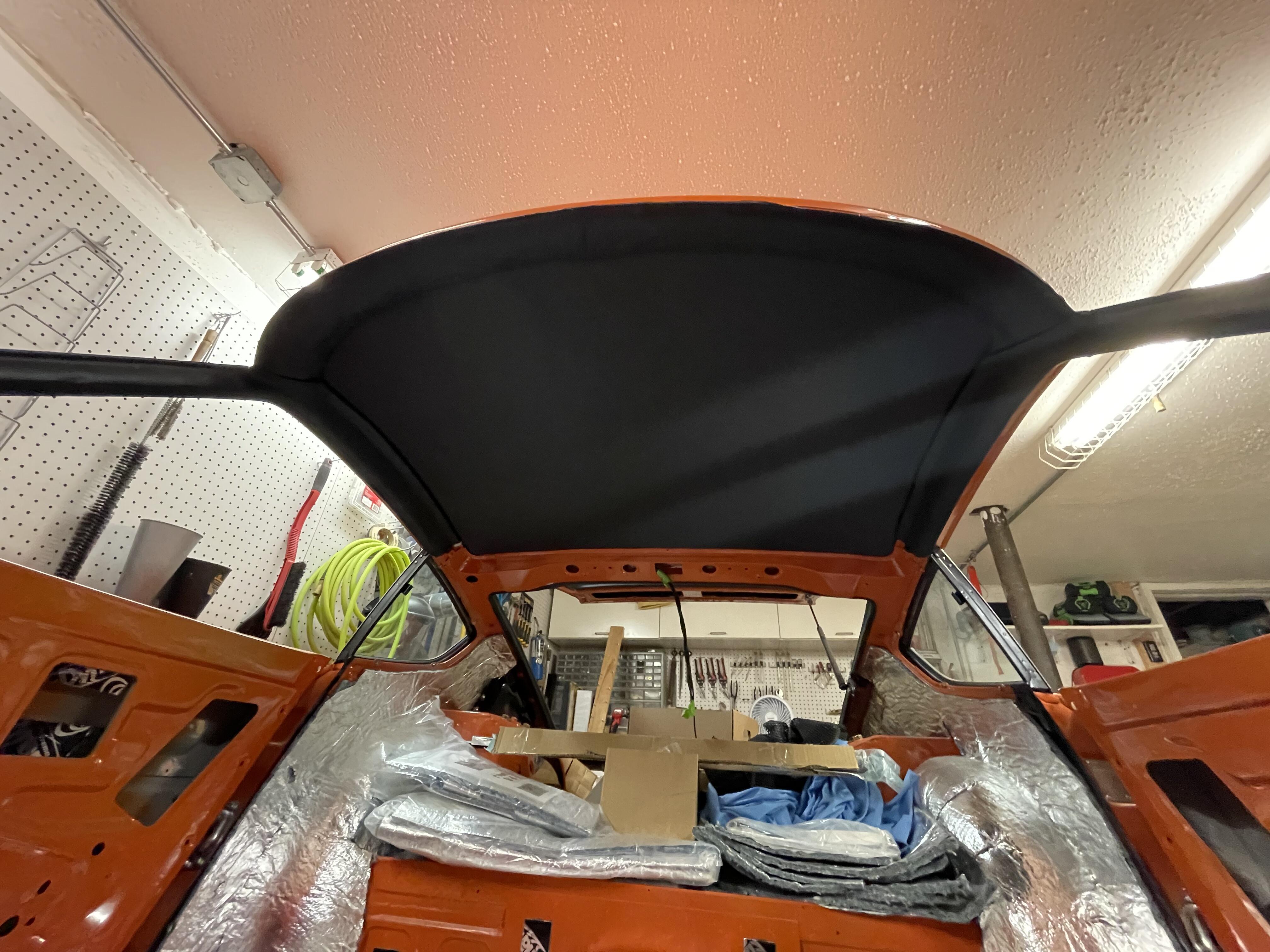
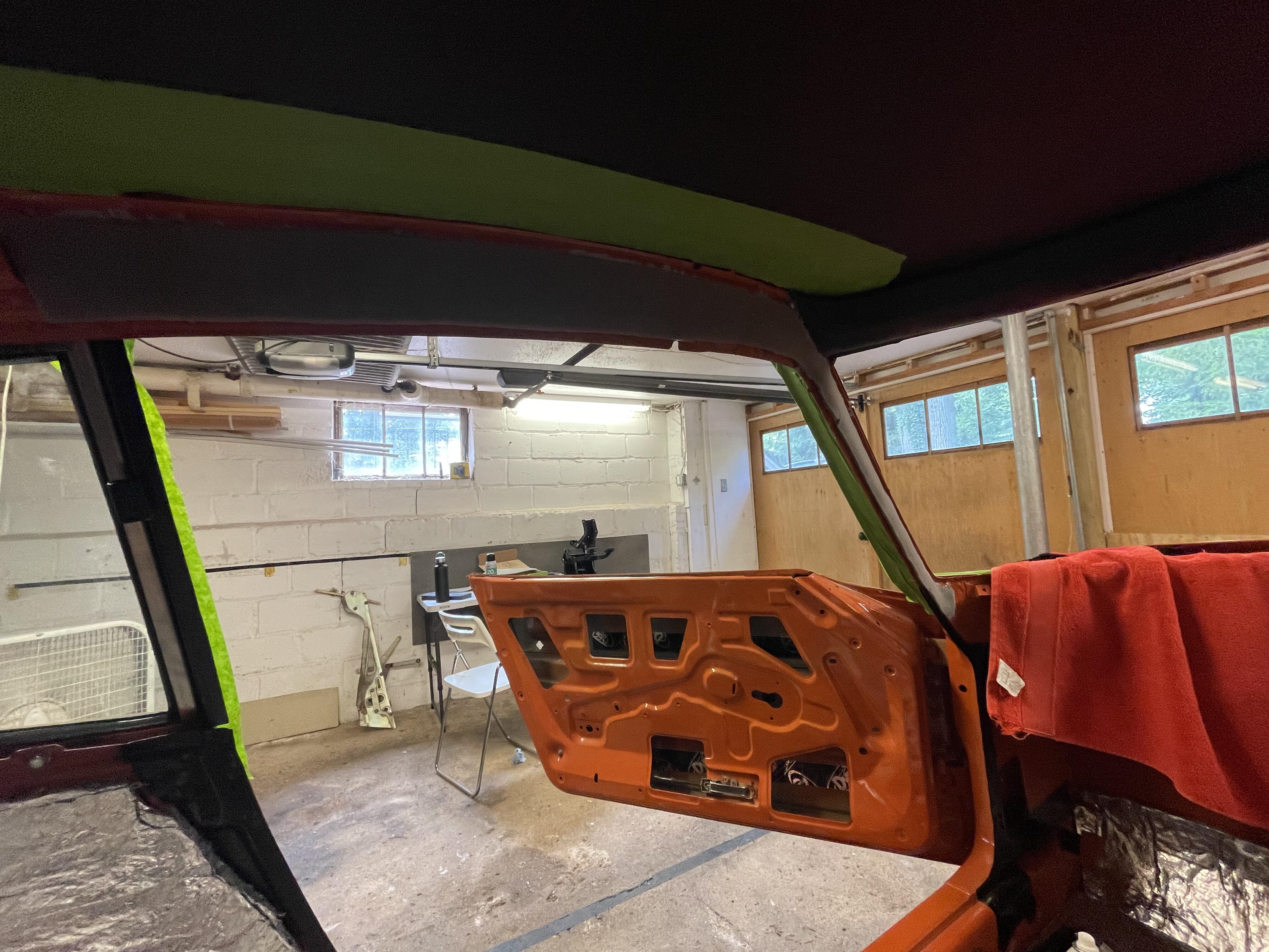
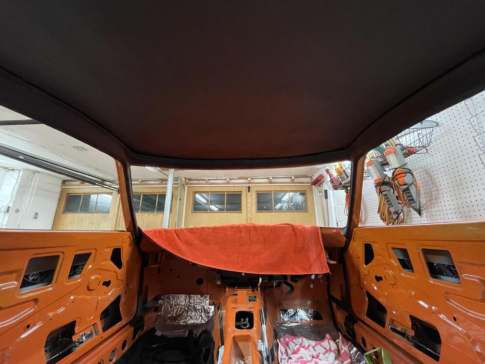
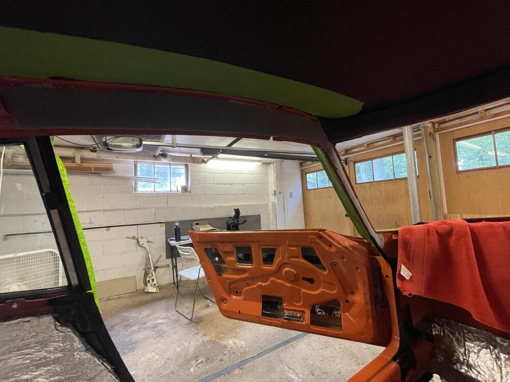
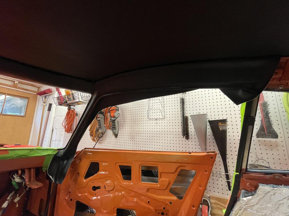
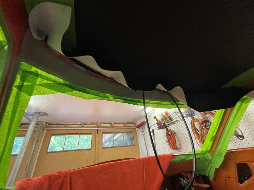
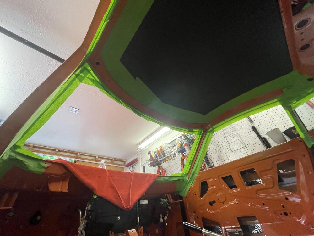
I’ve been neglecting this thread so I’m going to make a series of updates in quick succession… After much messing about I was able to close my coolant circuit. It was not easy. I had to order an entire set of clamps because I had the wrong size in eight (!) places. Luckily a friend of mine has a vacuum system for checking this and I got it sorted. She held vacuum for an hour so I’m confident it will be good. Despite being reassured by the seller that it had been tested, it turns out my coolant regulator leaks, so I swapped it for an open T fitting until I can repair it. Yeah, I know there’s a source for NOS ones, but I’m not paying his prices. ••• Vibe change. This vinyl pillar trim really changed how the inside of the car feels. Now I feel some urgency to get the windows in to keep the dust out. I’m 90% happy with how this came out. There is some unevenness I am hoping will come out as the vinyl settles in the same way it did in the head liner. I would try the heat gun on it but I’m too paranoid, plus my garage is hot enough I don’t really need to. If anything I’m nervous the glue will fail because of the heat. It’s an easy kit, but I made a critical error and used the wrong piece for the front, so I have to make the pieces work, which required some extra persuasion (see last photo for the pucker at the rearview mirror that should be hidden by the bracket). I’m sure if I had my mind right and took my time it would have been a cinch.


-
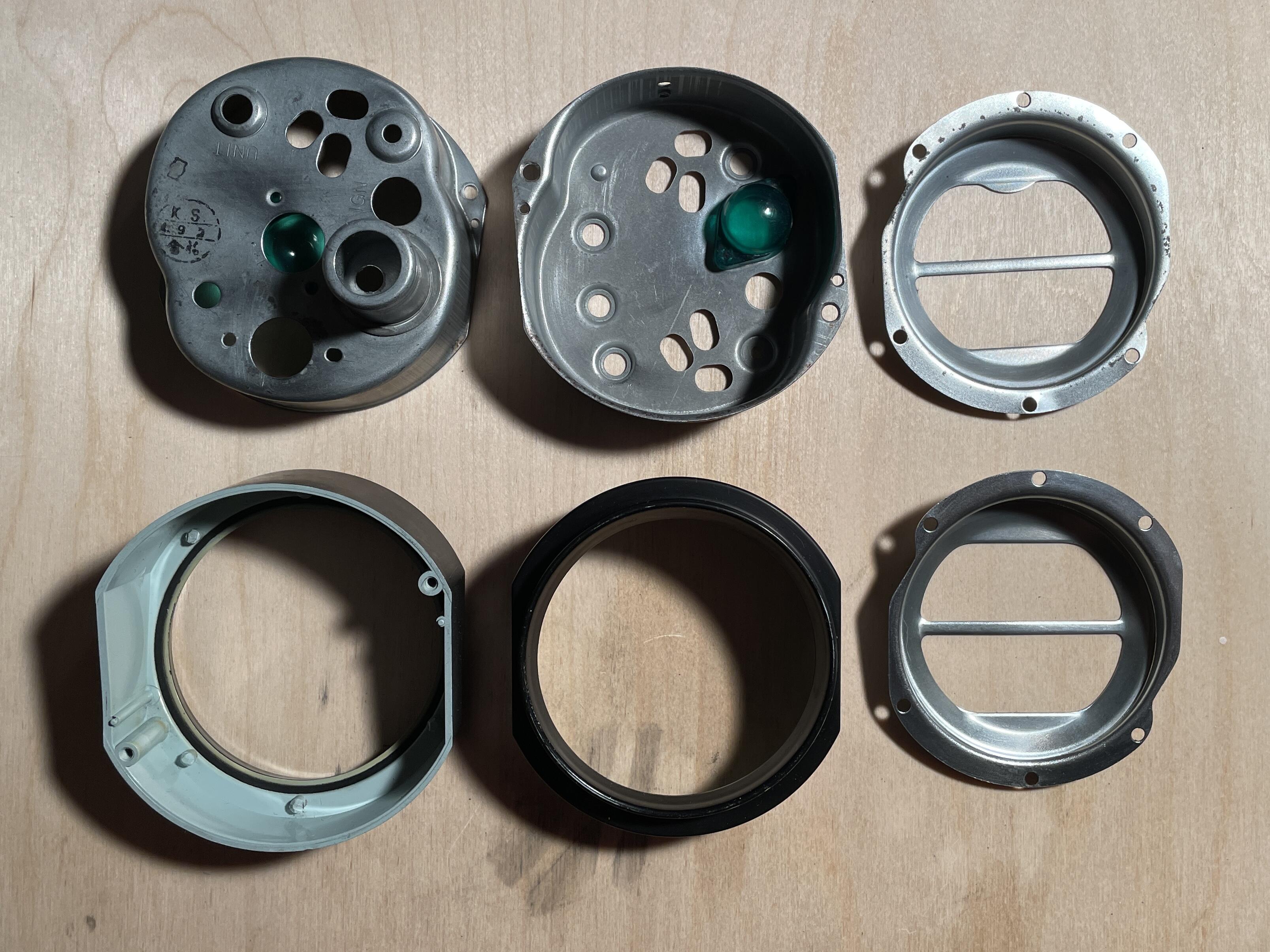
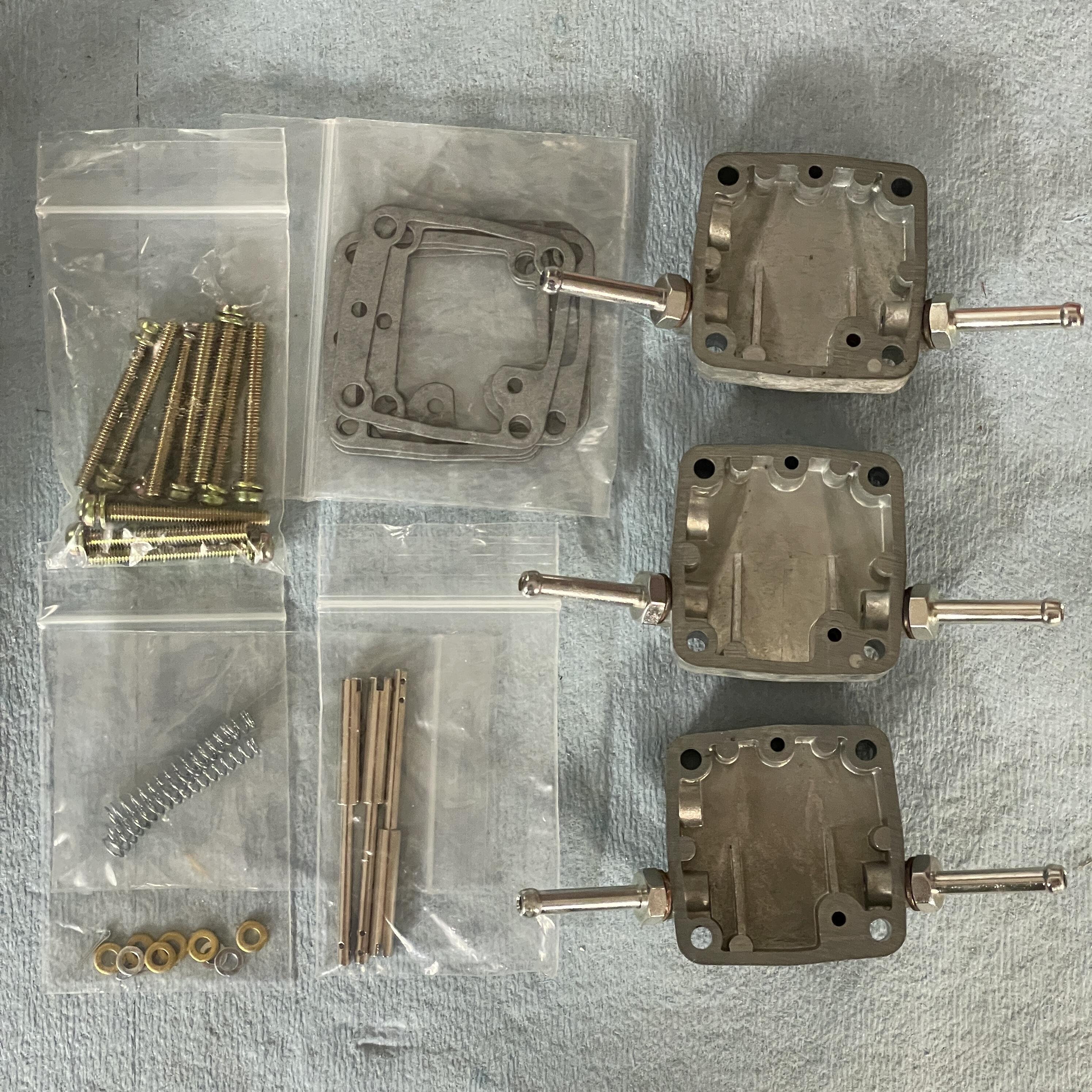
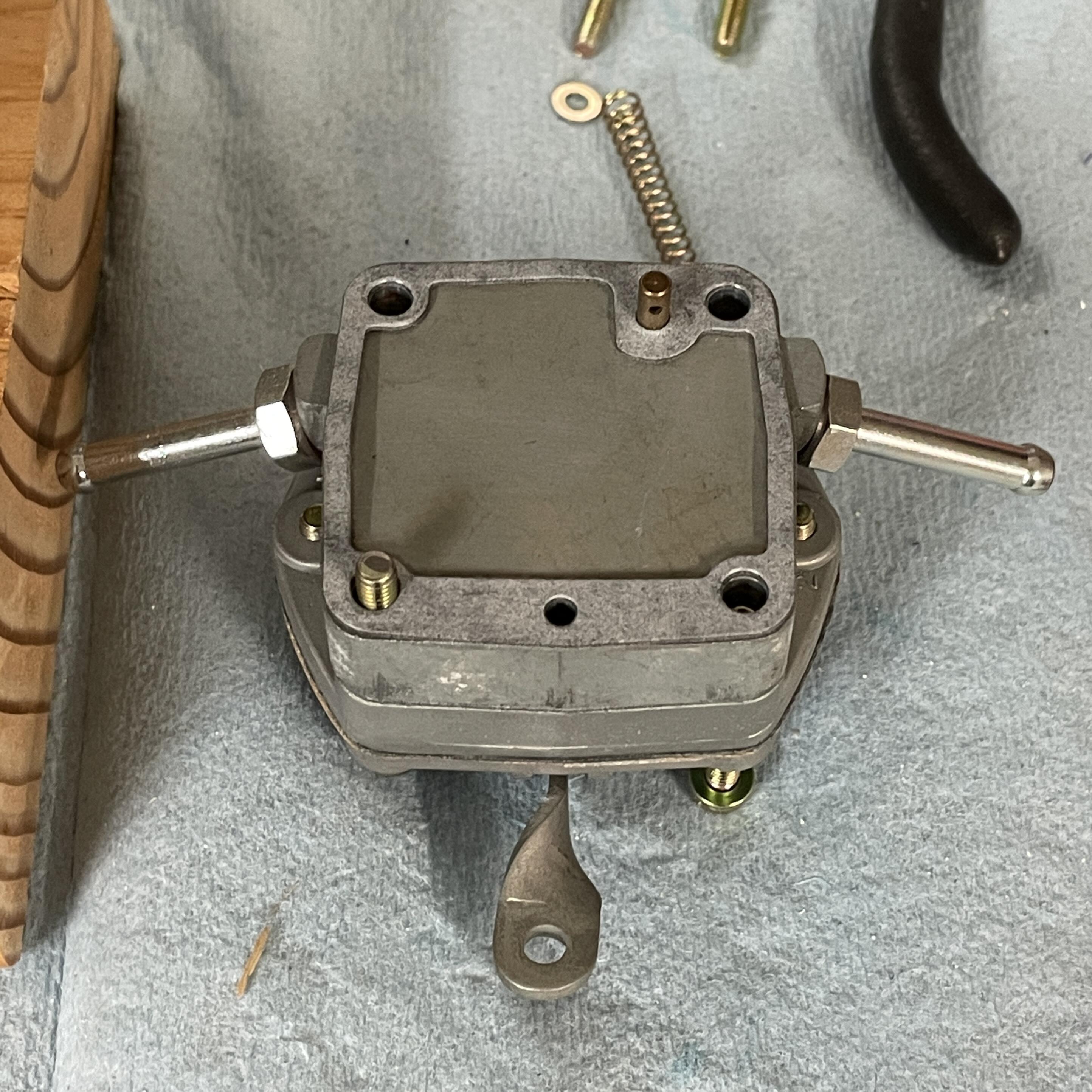
Okay, ran into another hurdle (although minor): My middle carburetor has a ball plugging the vacuum port. Yes, I know people don’t use vacuum advance with these, but I’m investigating solutions to that and this is stopping me. Does anyone know how to get it out? I’m not sure how to remove the vacuum port. It’s probably pressed in. I have a feeling I’ll have to use a drill.

-
Thanks! It depends on whether or not I make the dashboard wiring harness a blocker. If I don’t then I only need to jump some wires in the engine harness, make battery cables, fill the radiator, and bypass the heater. I have everything necessary to do those things, so I could theoretically finish all of that in a week. I also need to decide if I am going to fill the gas tank now or have the supply come from an external tank. Oh, and I need to get the transmission into neutral without having a shift stick, clutch cylinder, or clutch pedal in the car.
-
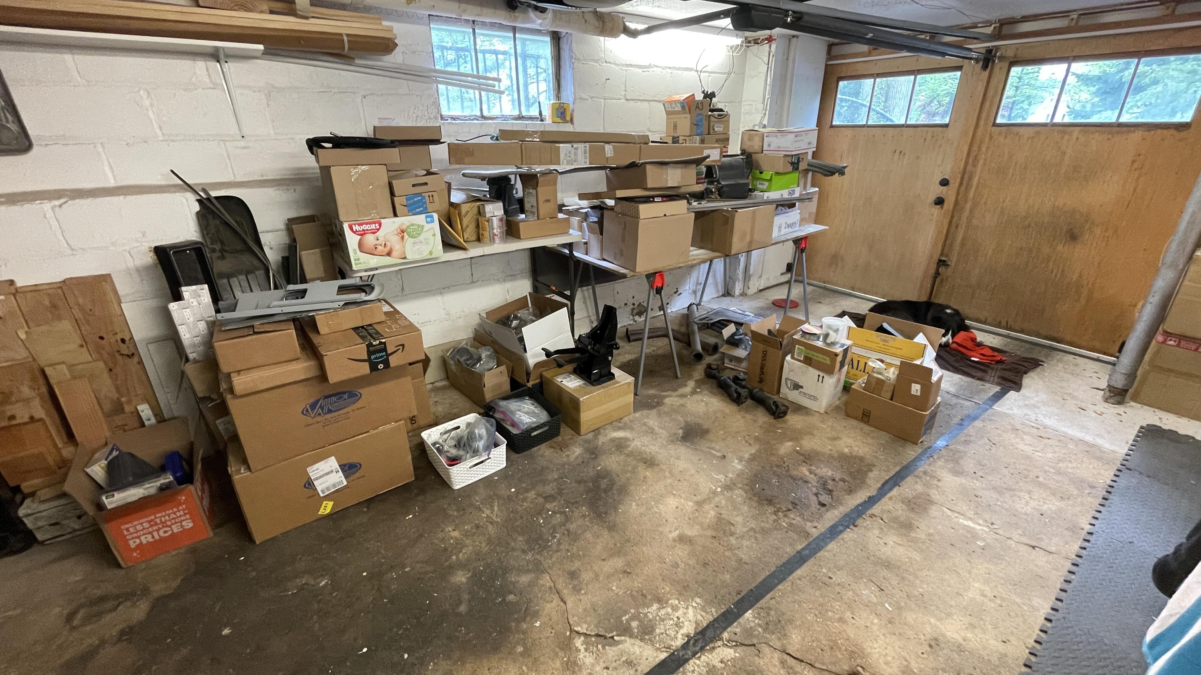
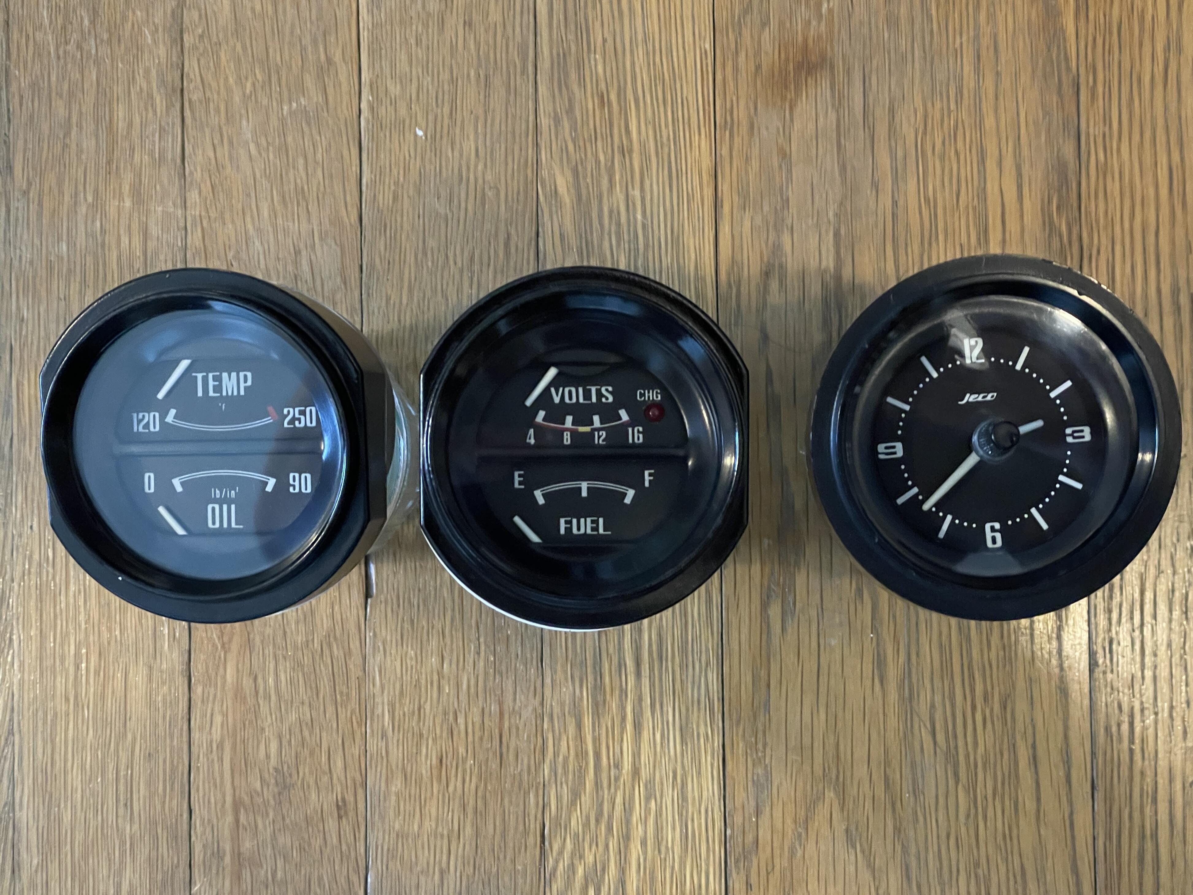
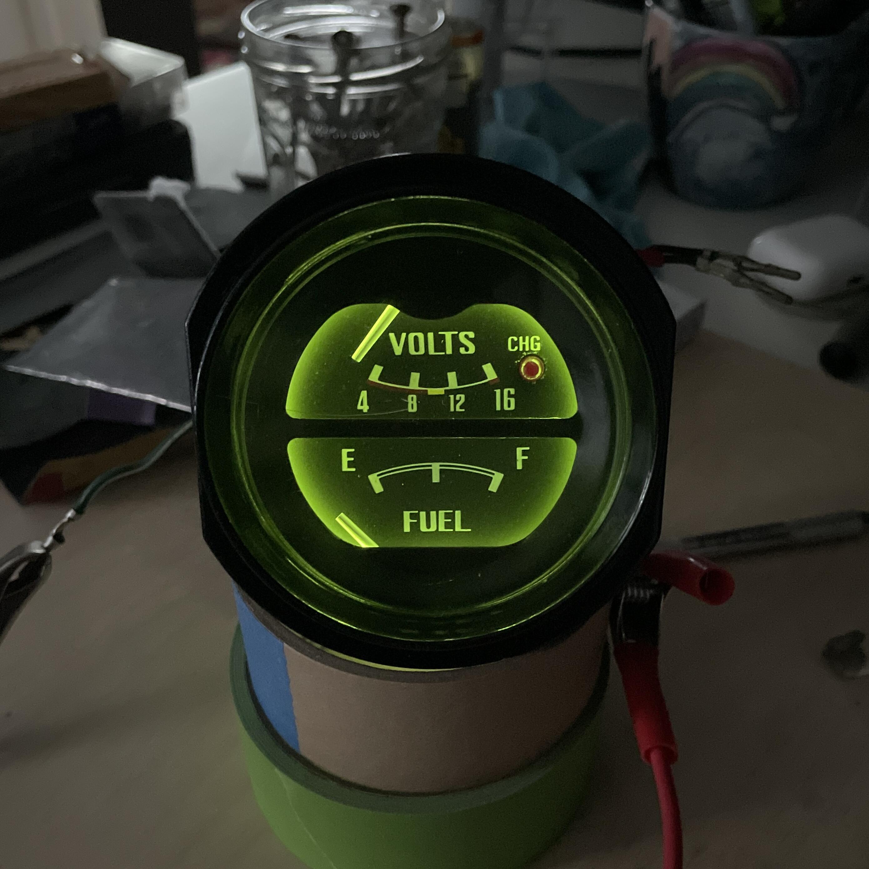
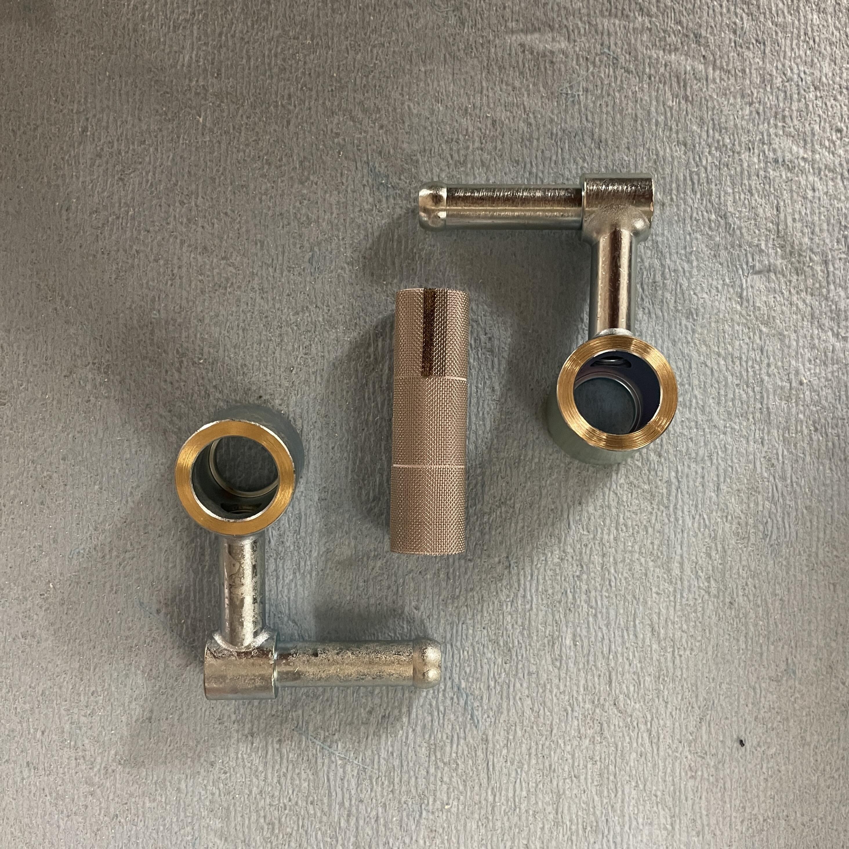
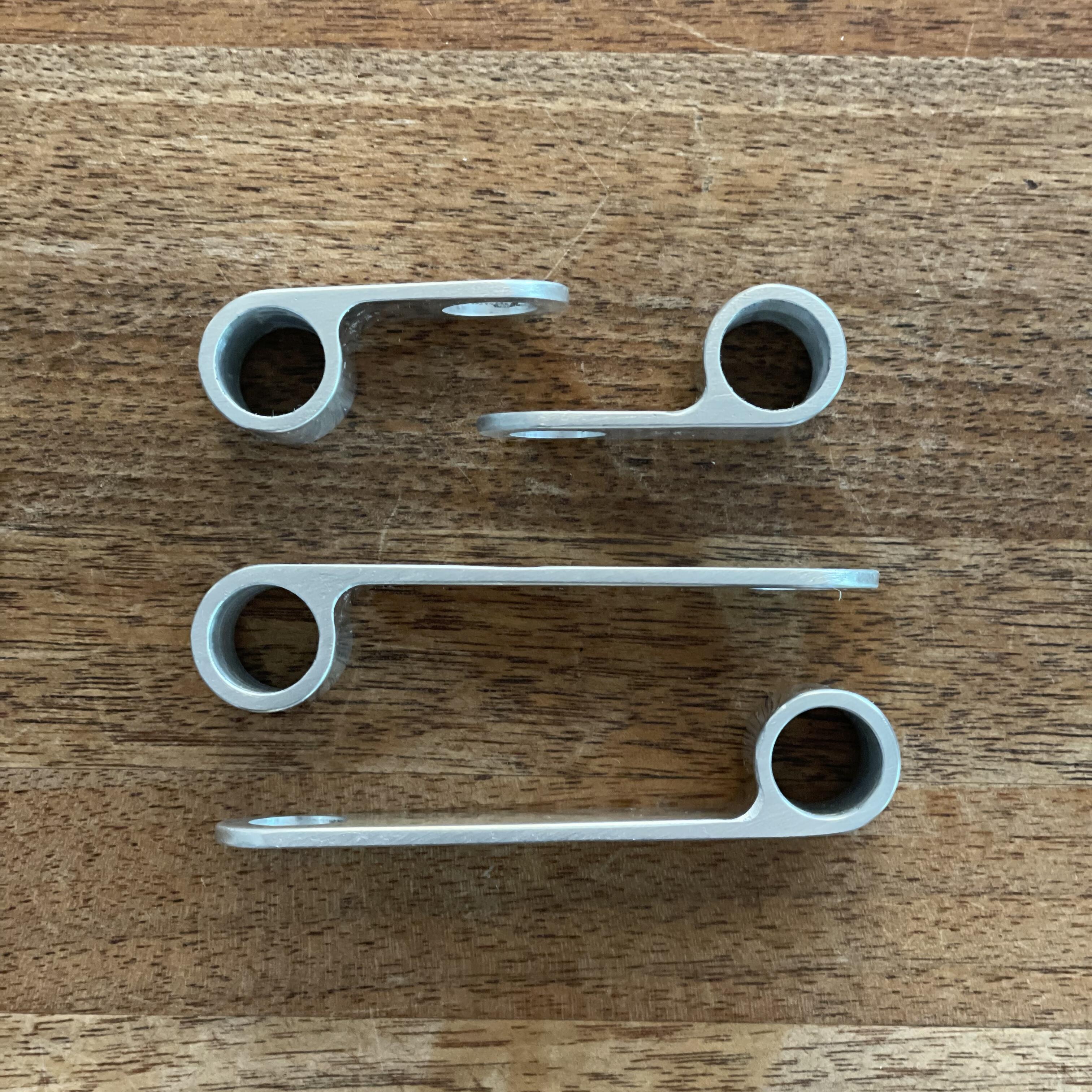
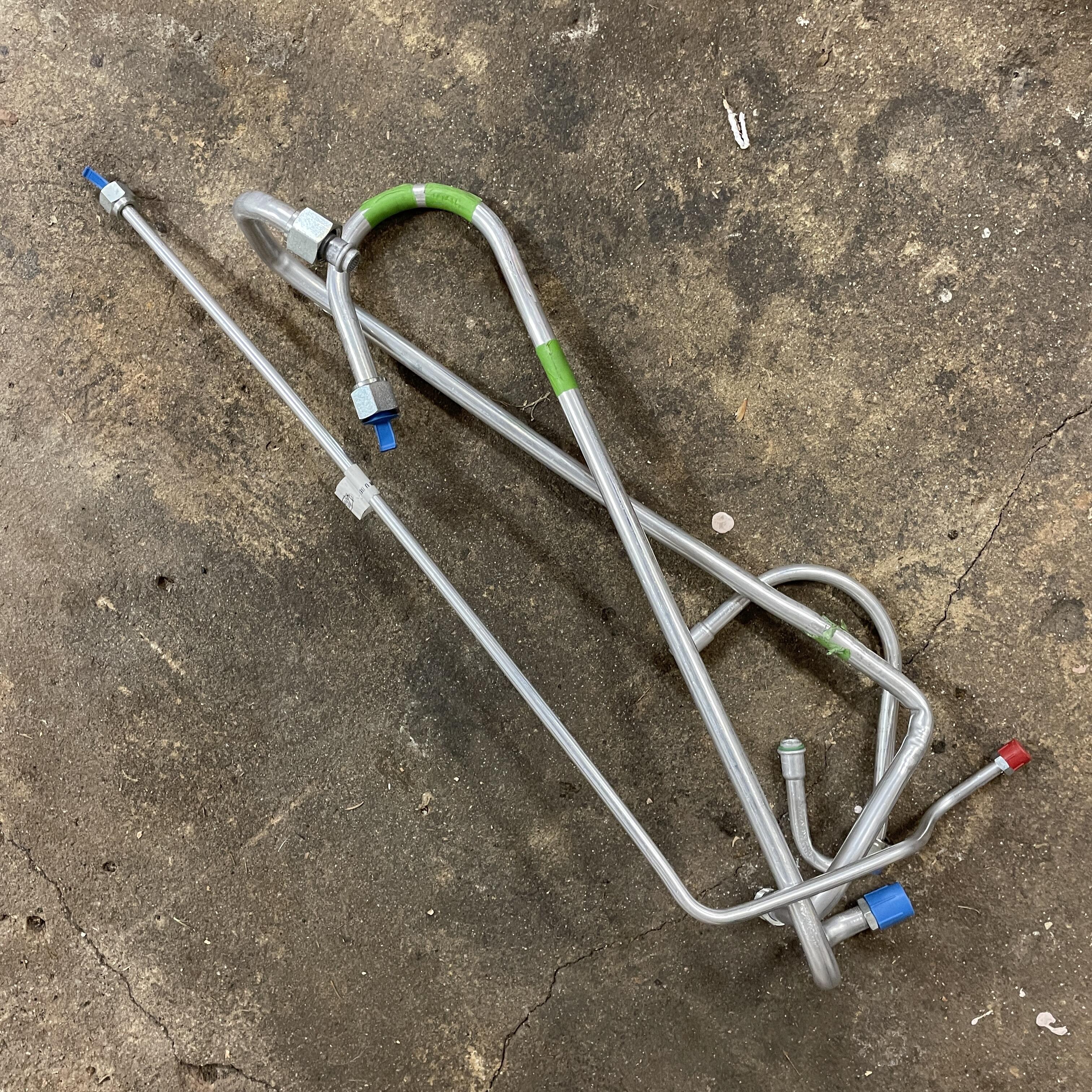
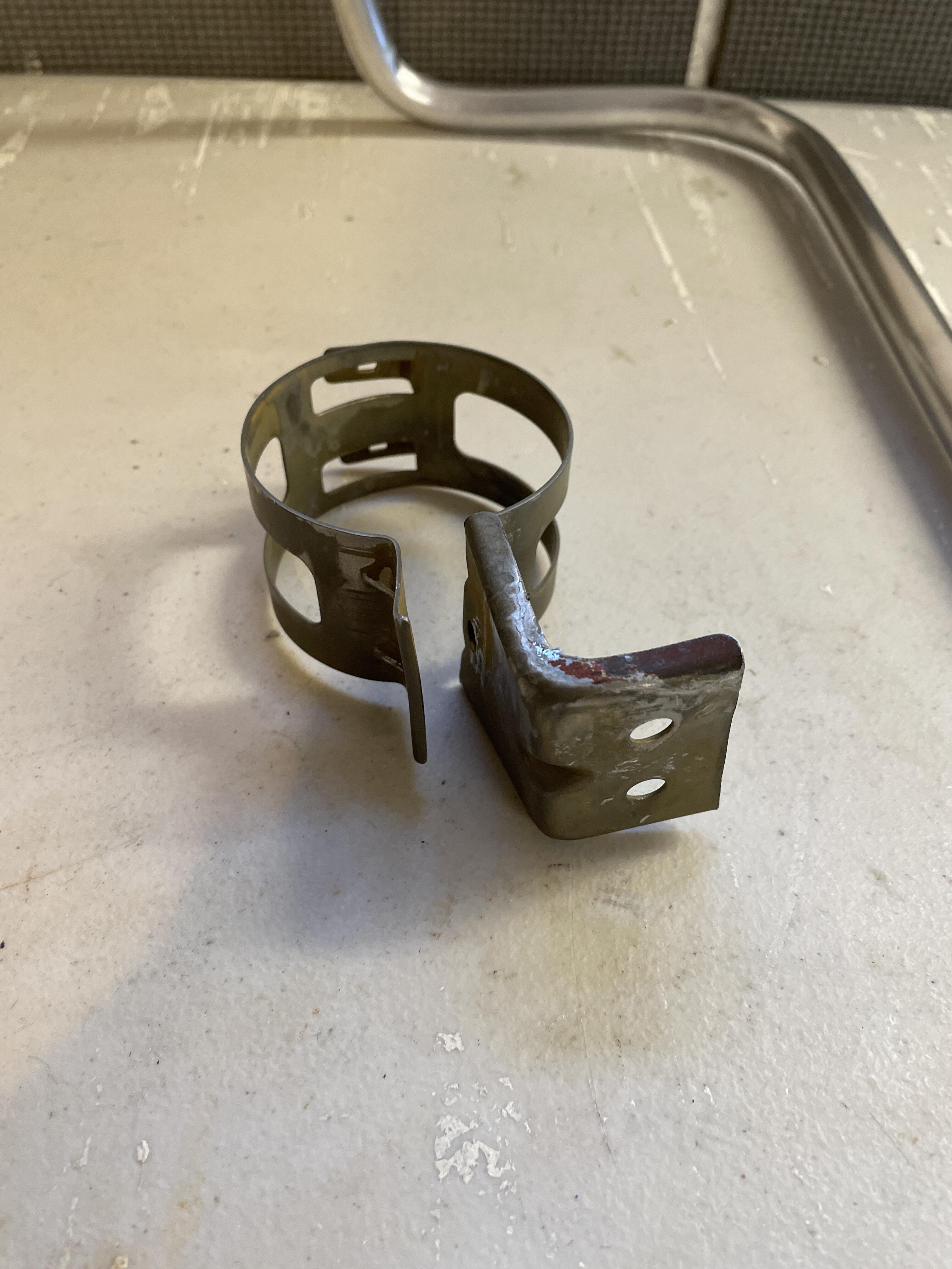
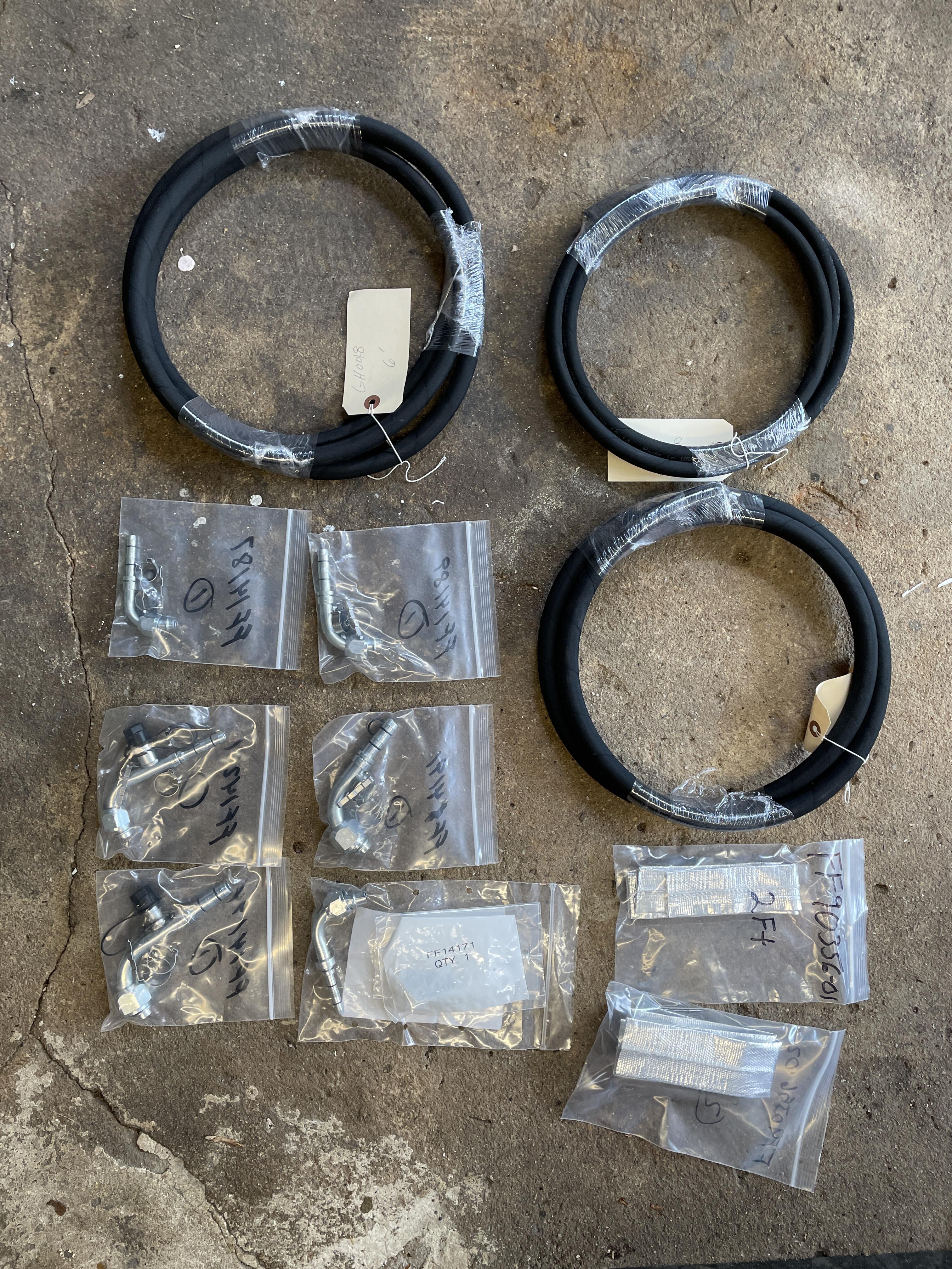
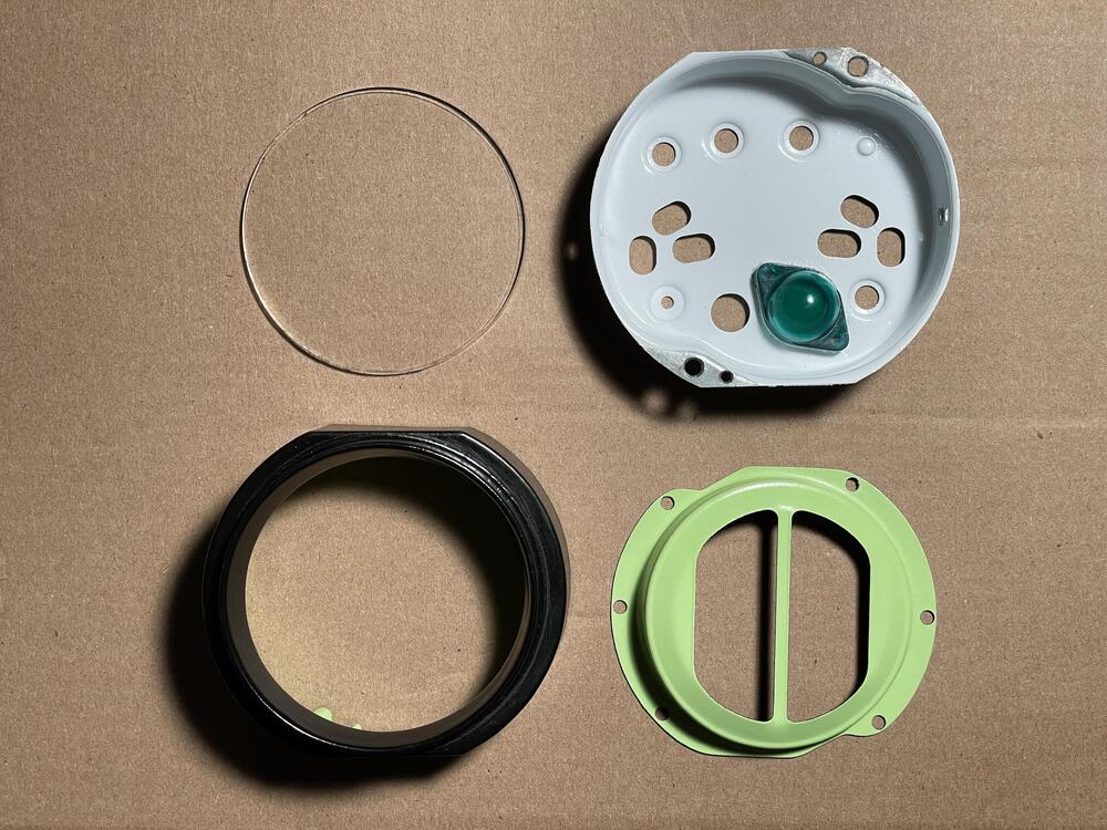
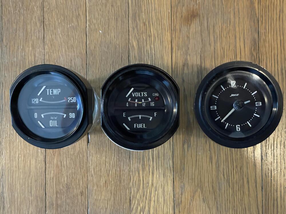
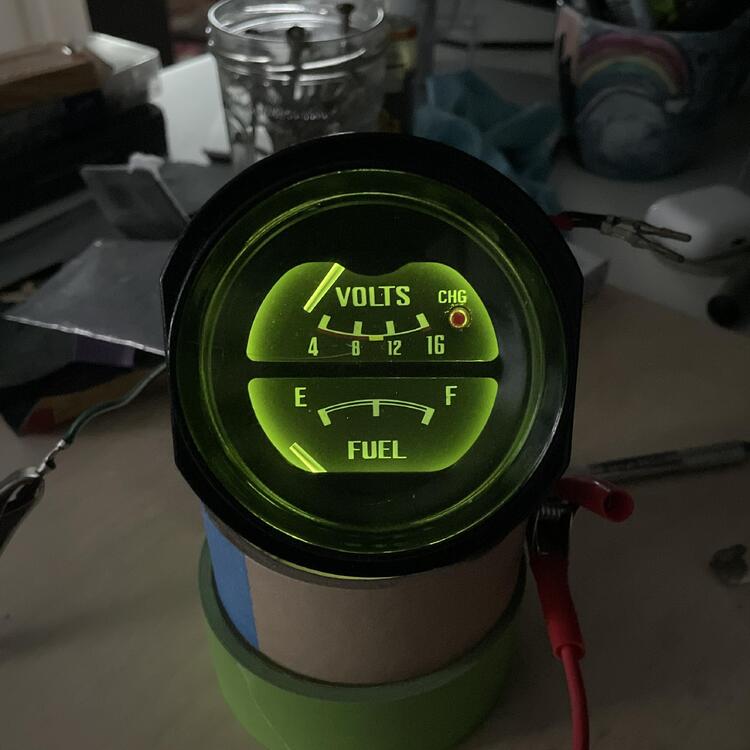
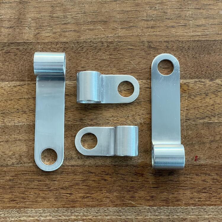
Some progress: Reboxed all my parts. It really drove home how much work I still have in front of me. ••• Wrapped up the remaining AC lines. Pretty pleased with how these turned out. Hopefully they don’t have any leaks! ••• Refinished and rebuilt my gauges. I matched the green to the inside of my clock rather than the blue from the gauges because the clock was in the best shape. Is it correct? ¯\_(ツ)_/¯ I used warm LEDs, which helped to knock back the intensity of the color. I’m still investigating PWM options to control their brightness. ••• Added some filter screens and cooling bodies to my carburetors. ••• Made some hose retainers for the fuel lines with a friend’s CNC machine. ••• Wrapped up the fuel lines. I may make a rail to clean up some of those cooling body hoses, but it will work for now.


-

1973 240z Custom Wiring From Scratch
Matthew Abate replied to Matthew Abate's topic in Build Threads
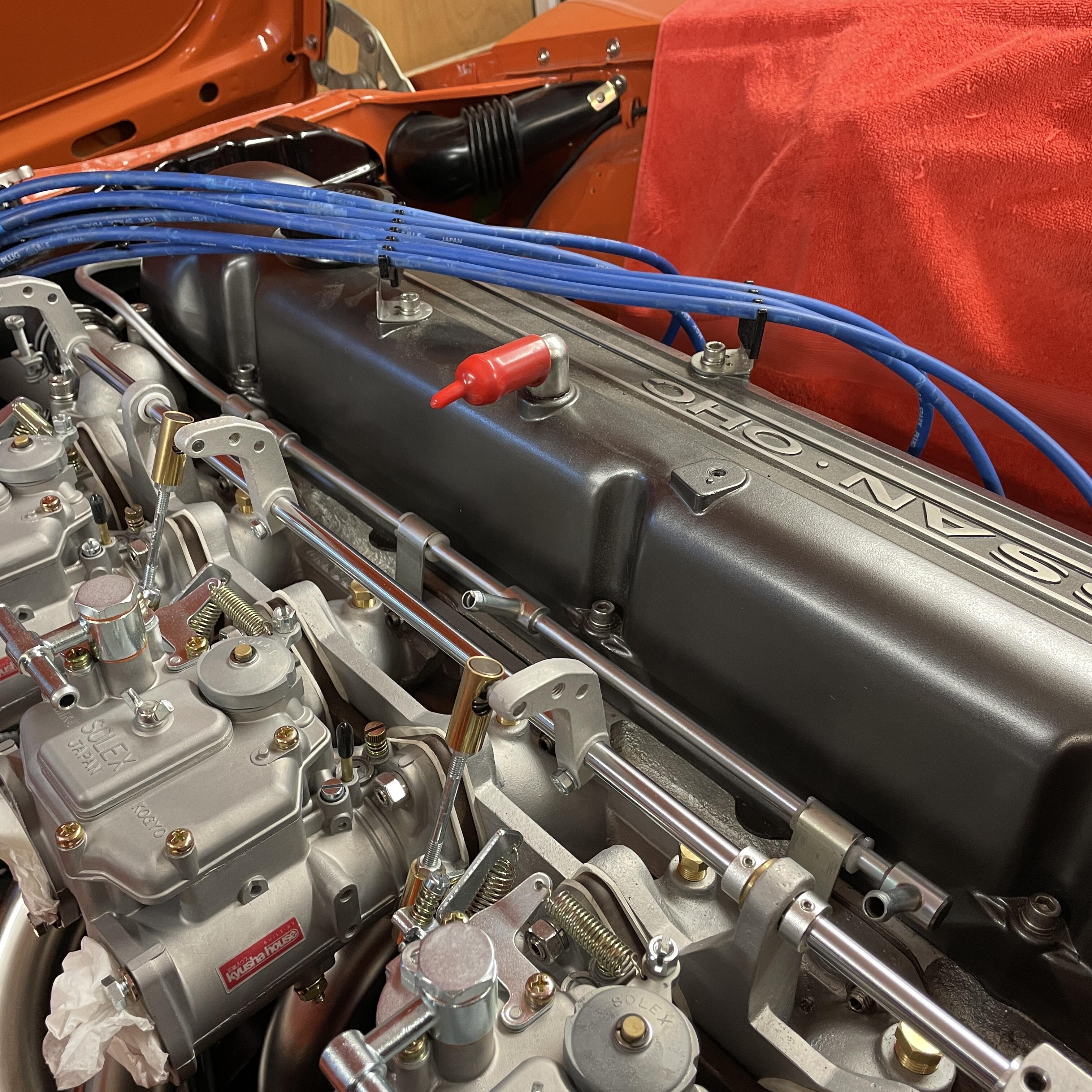
I’m hoping someone can clarify some things for me: I would like to put something approximating the “correct” capacitor (aka condenser) on my coil and wire it up as original if possible. Z Car Depot describes the RFI suppression capacitor as plugging into the harness via a bullet connector. My harness was cut at several points because the previous owner was trying to force an AT harness to work in a manual, so I may have made a mistake when mapping everything to the wiring diagram. There is a B/W wire that splices to a green wire that ran to the voltage regulator and then through the firewall and to the green wires coming off the fuse box that supply power to the seatbelt switches & light and gauges. Could this B/W wire be what is supposed to connect to the capacitor? If so, that makes it easy. If not, I’ll just use it as an aux power feed and tape it back for any future needs. Secondly, is that even the best way to wire it up? I know others wire it directly to the positive pole on the coil. And last, does it matter what capacitance rating I use for this? The 280ZX (my engine and ignition are from a ZX) used a two-wire, 250v, .47uF capacitor. I have no idea what the 240z used. As far as I can tell, the .22uF ones were for the dizzy. I’ve found one from an RX-7 that has that rating, but it doesn’t look anything like the cylindrical ones from the ‘70s. I’ve also found some that are .50uF. Is that difference going to impact anything? Maybe this is trivial and I’m overthinking it, but like I said, I’d like to at least try to get it right. -
Back Pressure Regulator Recommendations?
Matthew Abate replied to Matthew Abate's topic in Triple Mikuni and Webers
@Yarb That would be fantastic! Thanks -
Back Pressure Regulator Recommendations?
Matthew Abate replied to Matthew Abate's topic in Triple Mikuni and Webers
I think you’re right after reading that article. Thanks for that! It was super helpful. So back-pressure regulators are all over the place in other applications. I can find info about them for construction and engineering, but not in an automotive context. I know about them from projects working with gasses and other liquids and just assumed they would be available for gasoline engines, but it looks like they just aren’t used in cars. I’ll dig into how a bypass regulator manages upstream pressure more and figure something out. If anyone has a setup like this they can share photos of, I’d appreciate seeing them. There’s not a ton of good documentation about placement and line routing in Z cars. -
Back Pressure Regulator Recommendations?
Matthew Abate replied to Matthew Abate's topic in Triple Mikuni and Webers
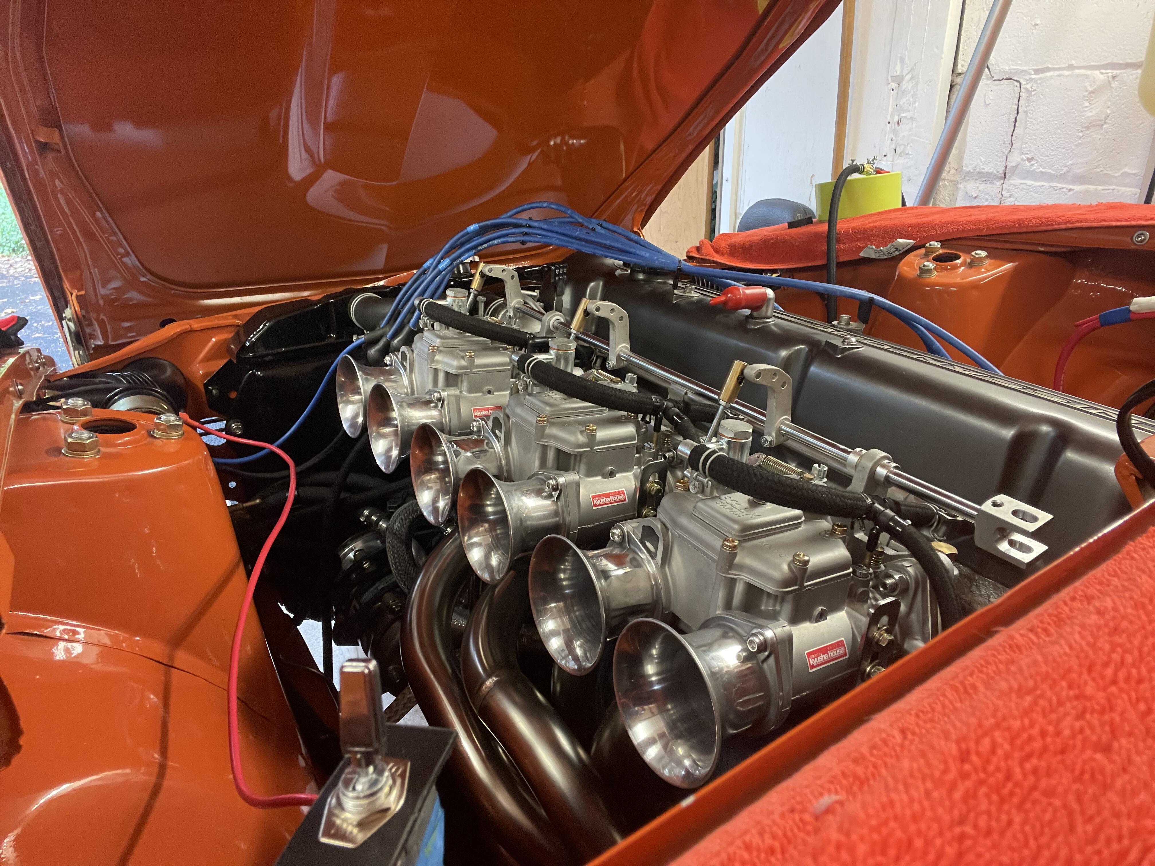
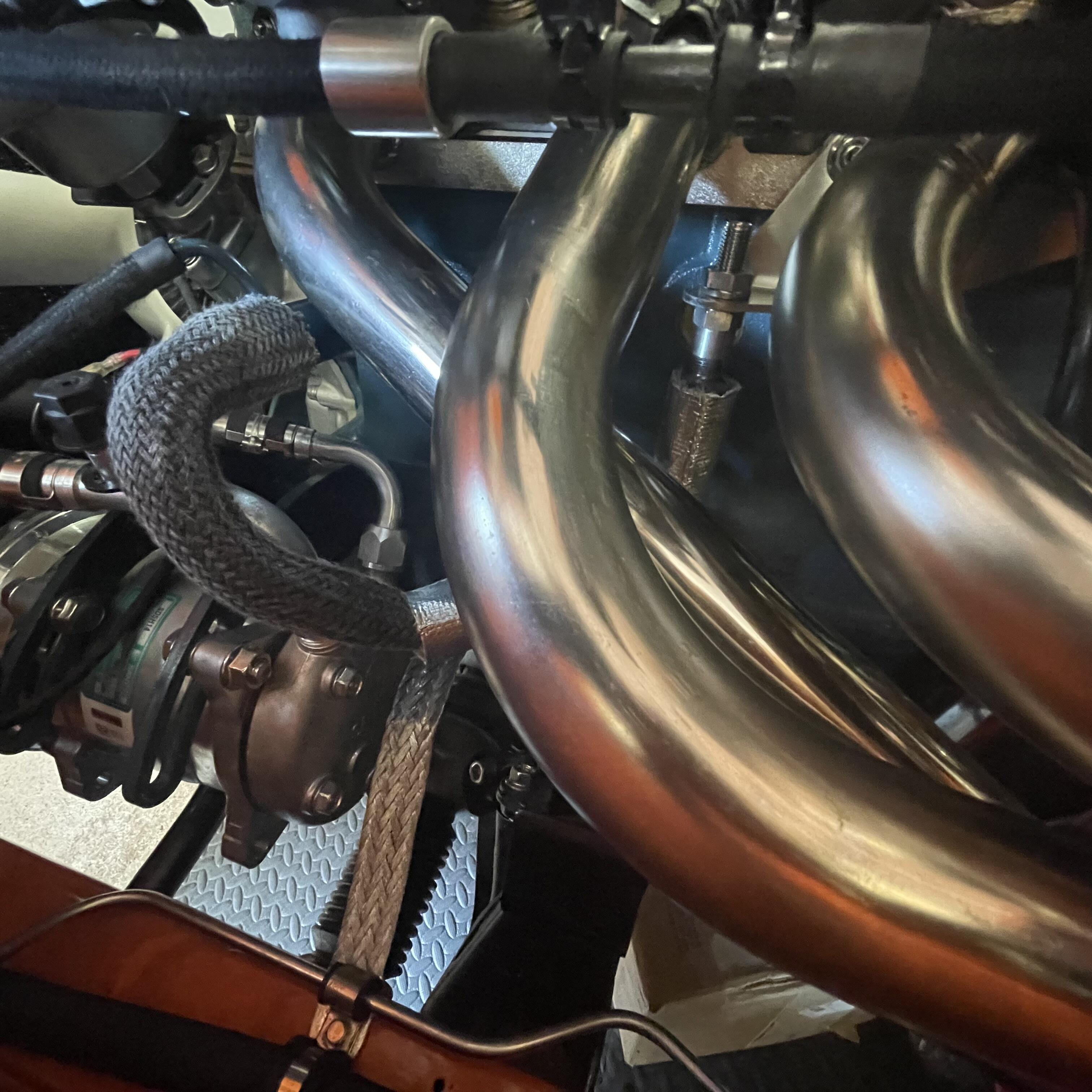
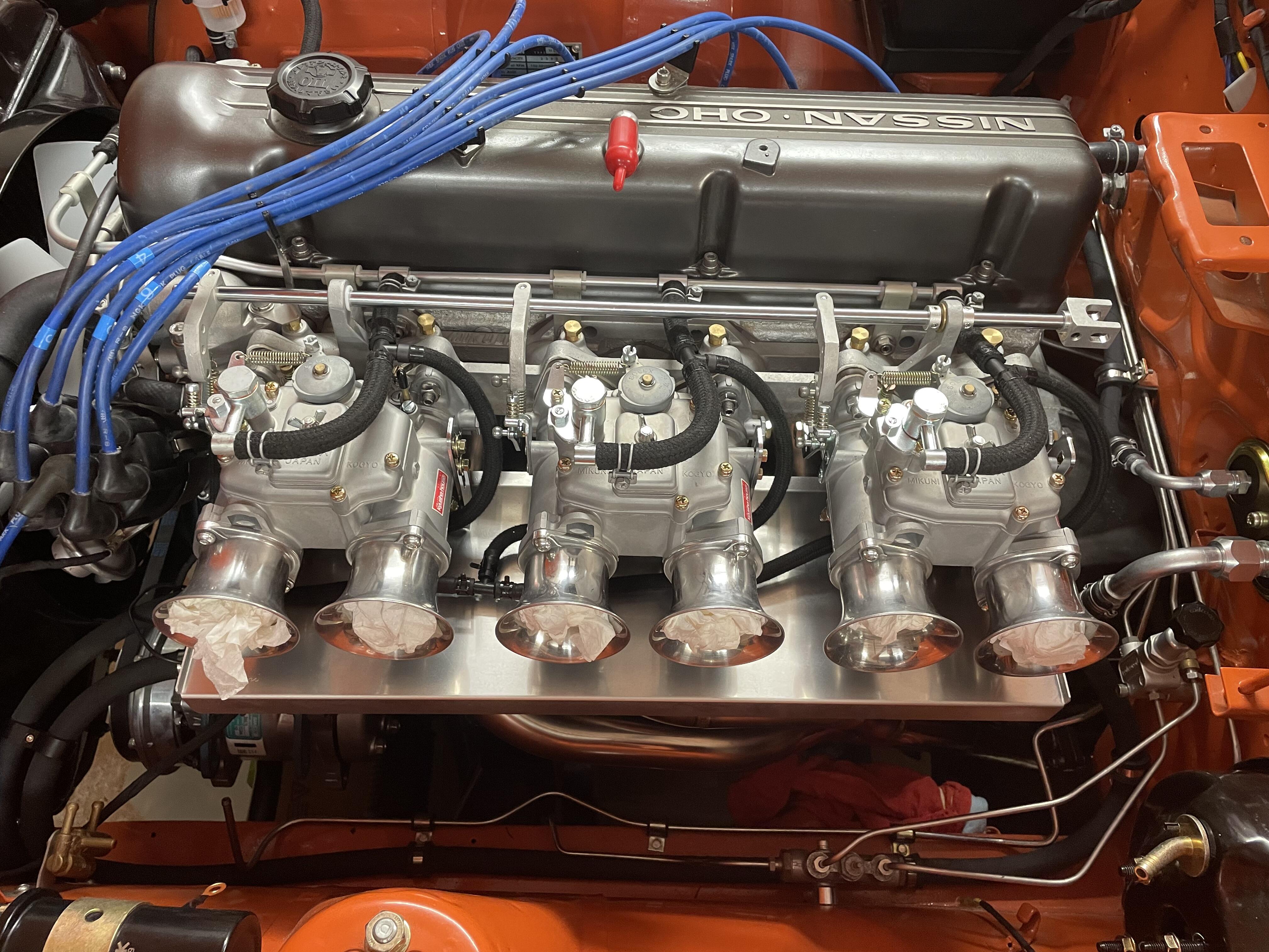
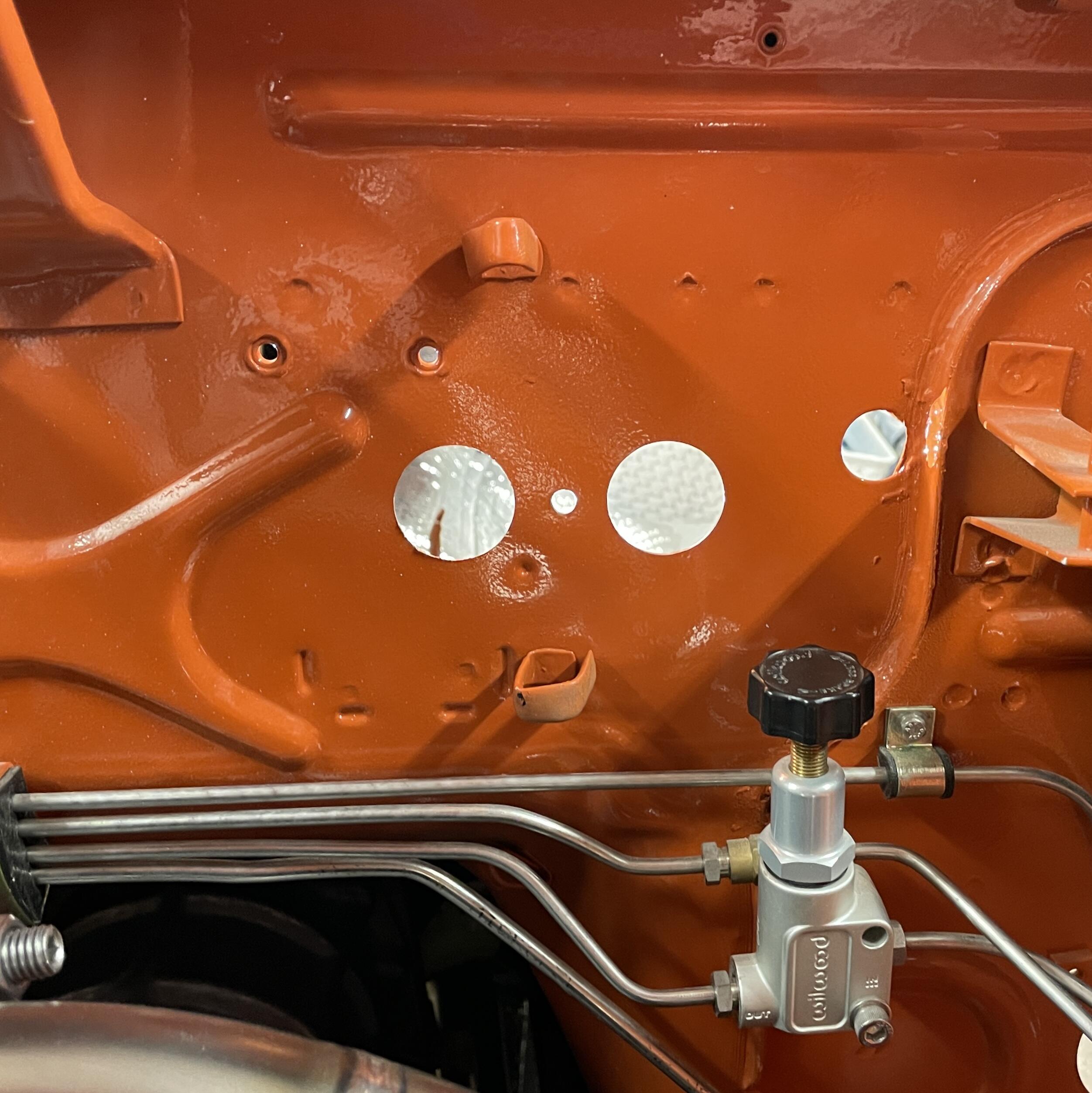
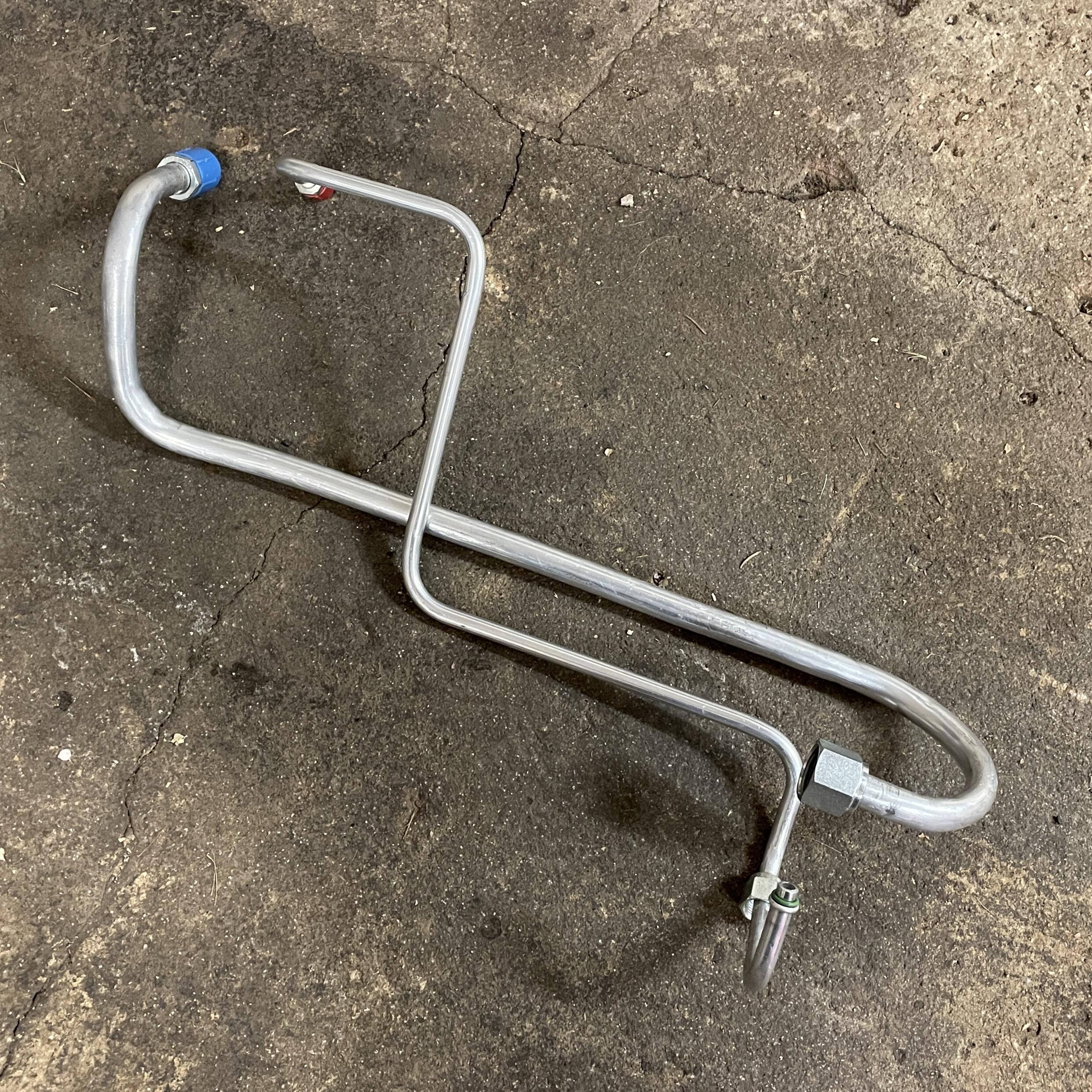
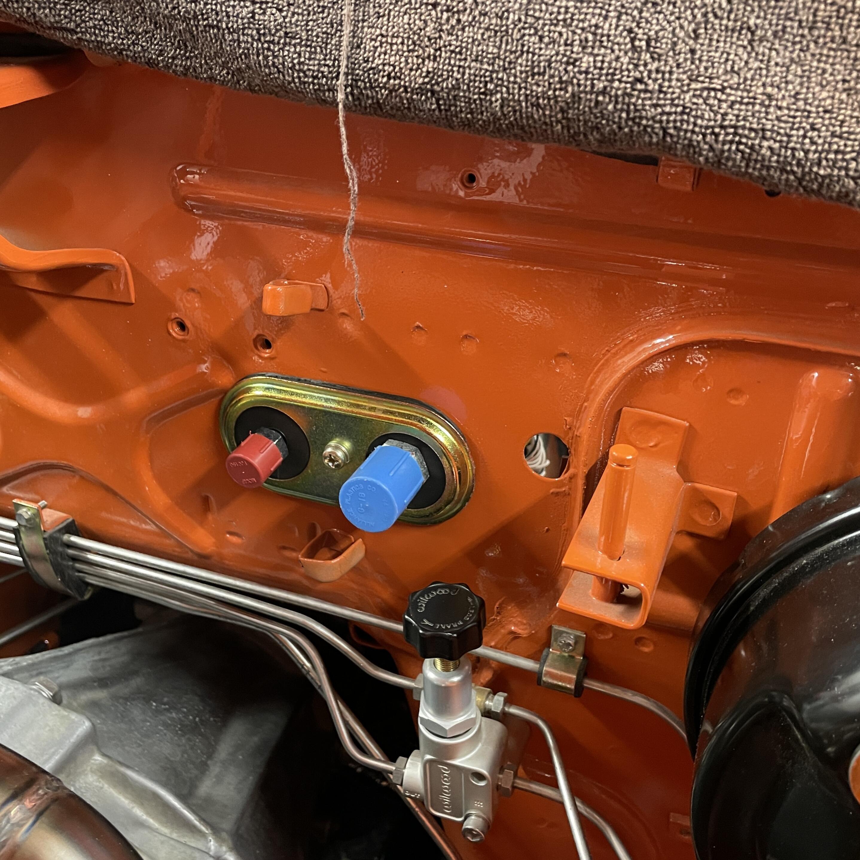
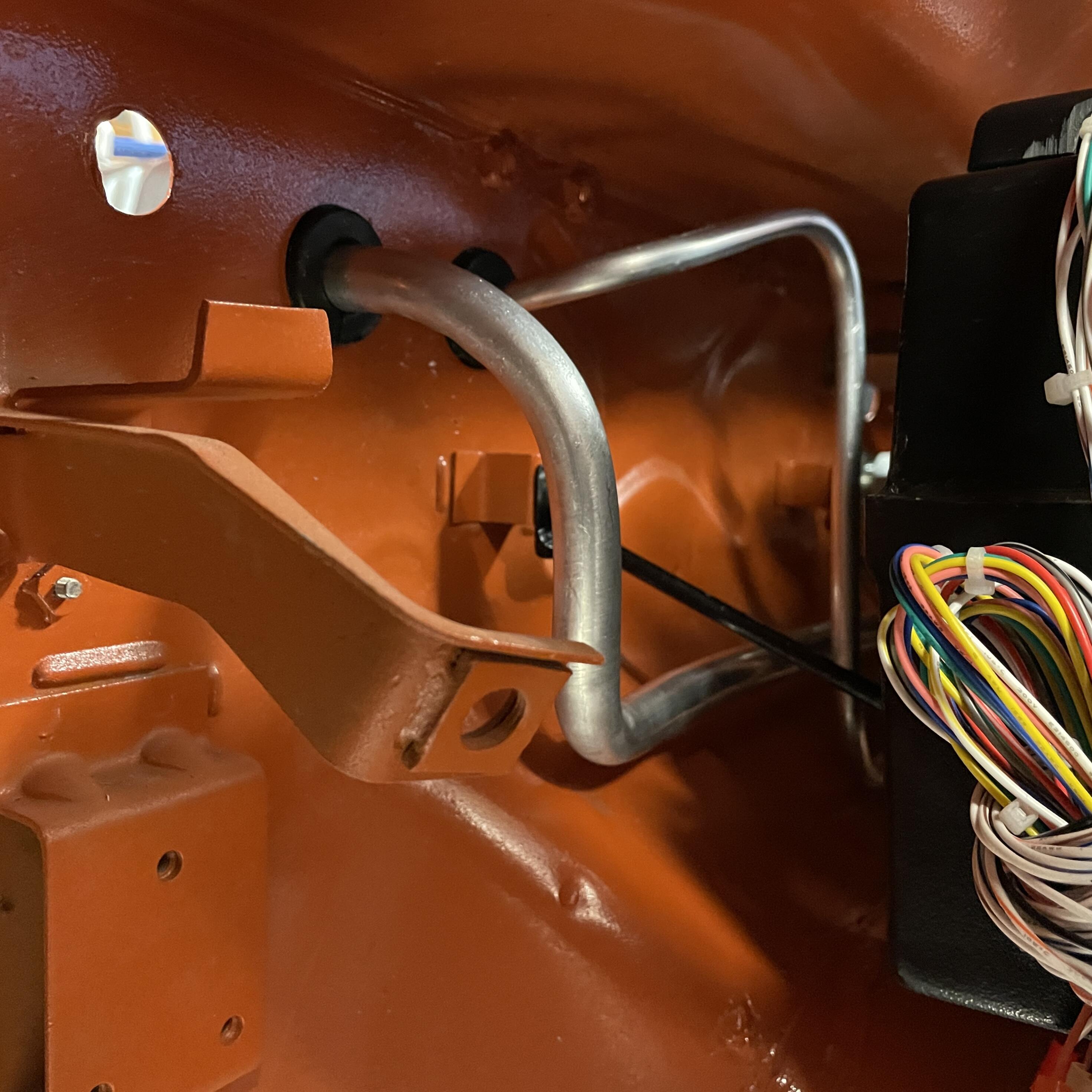
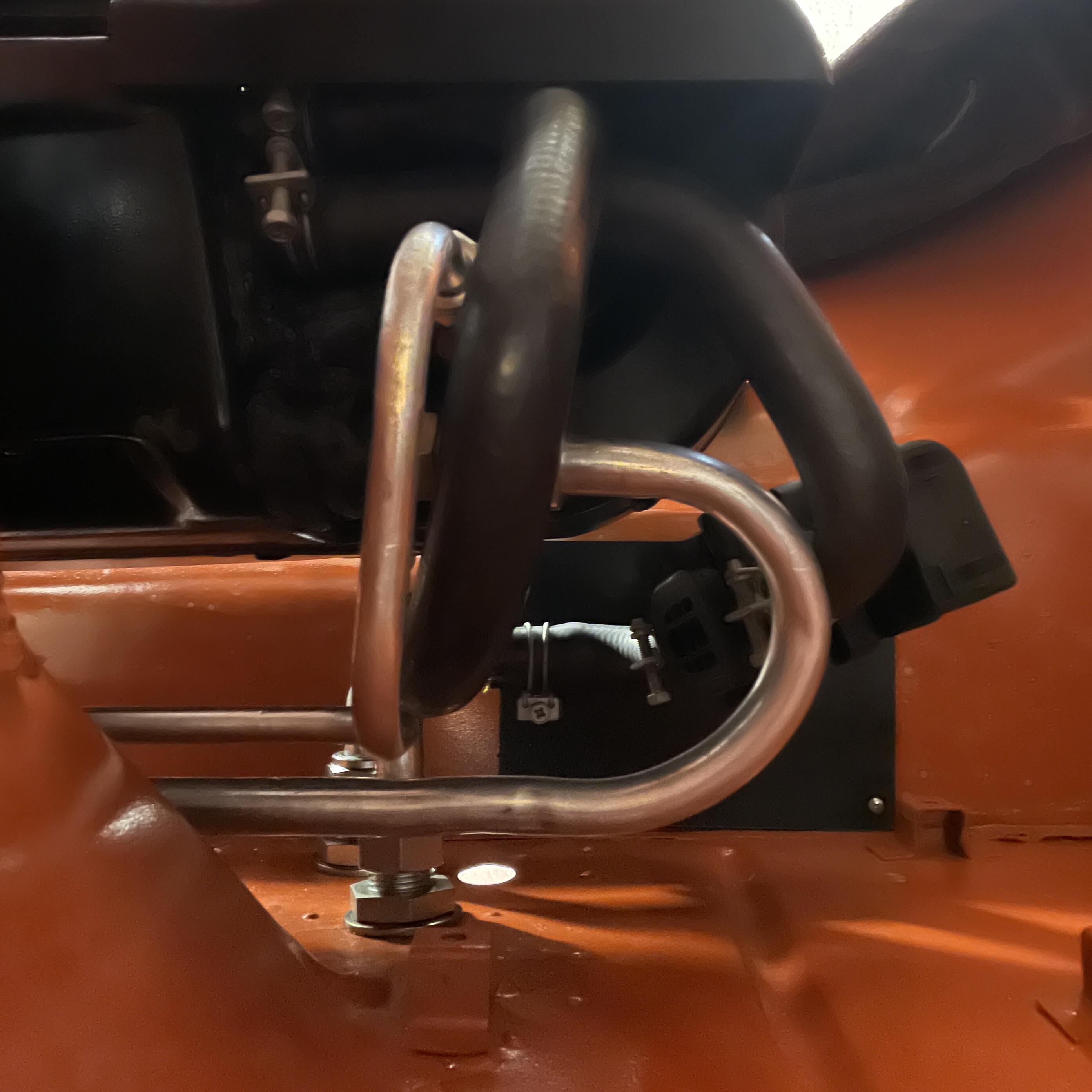
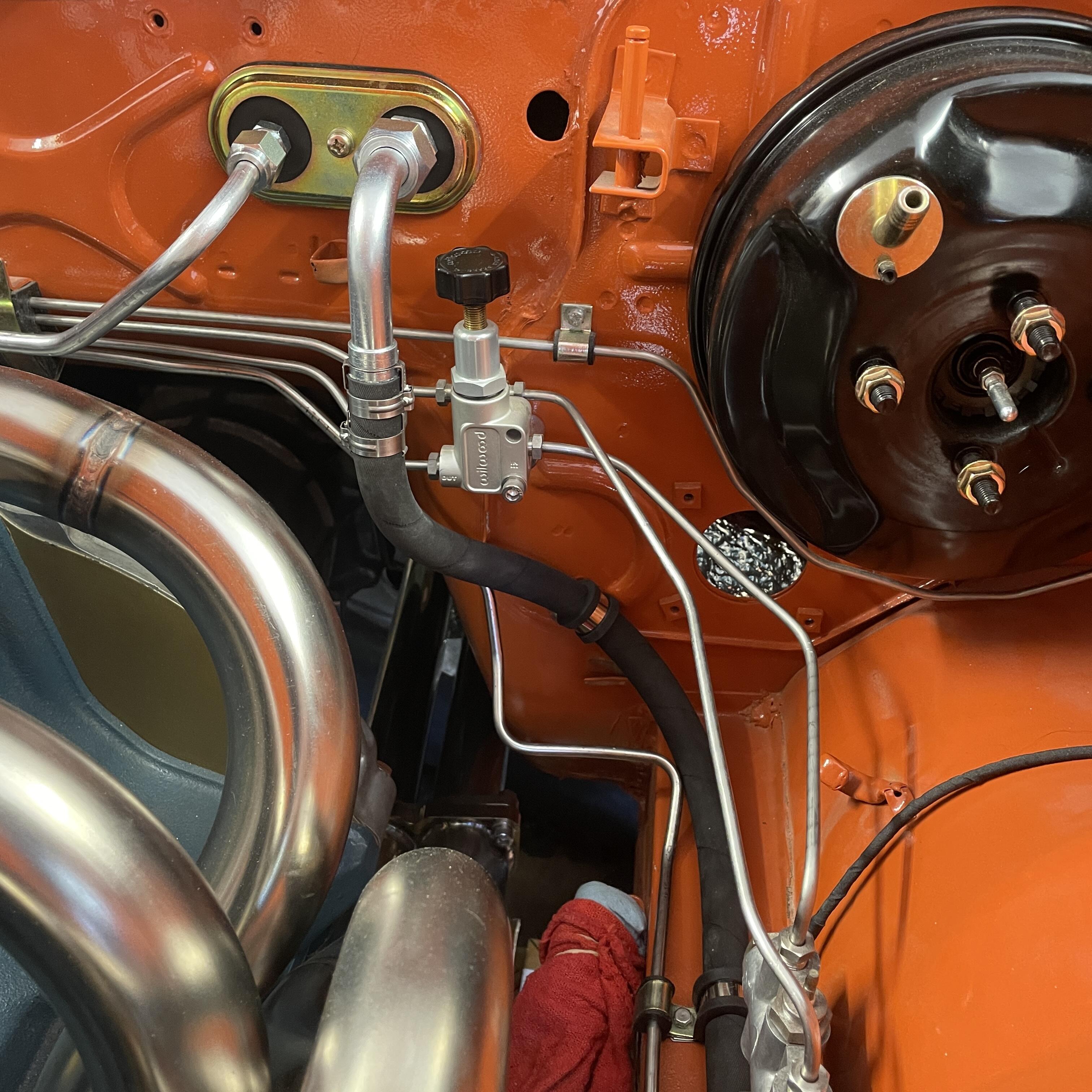
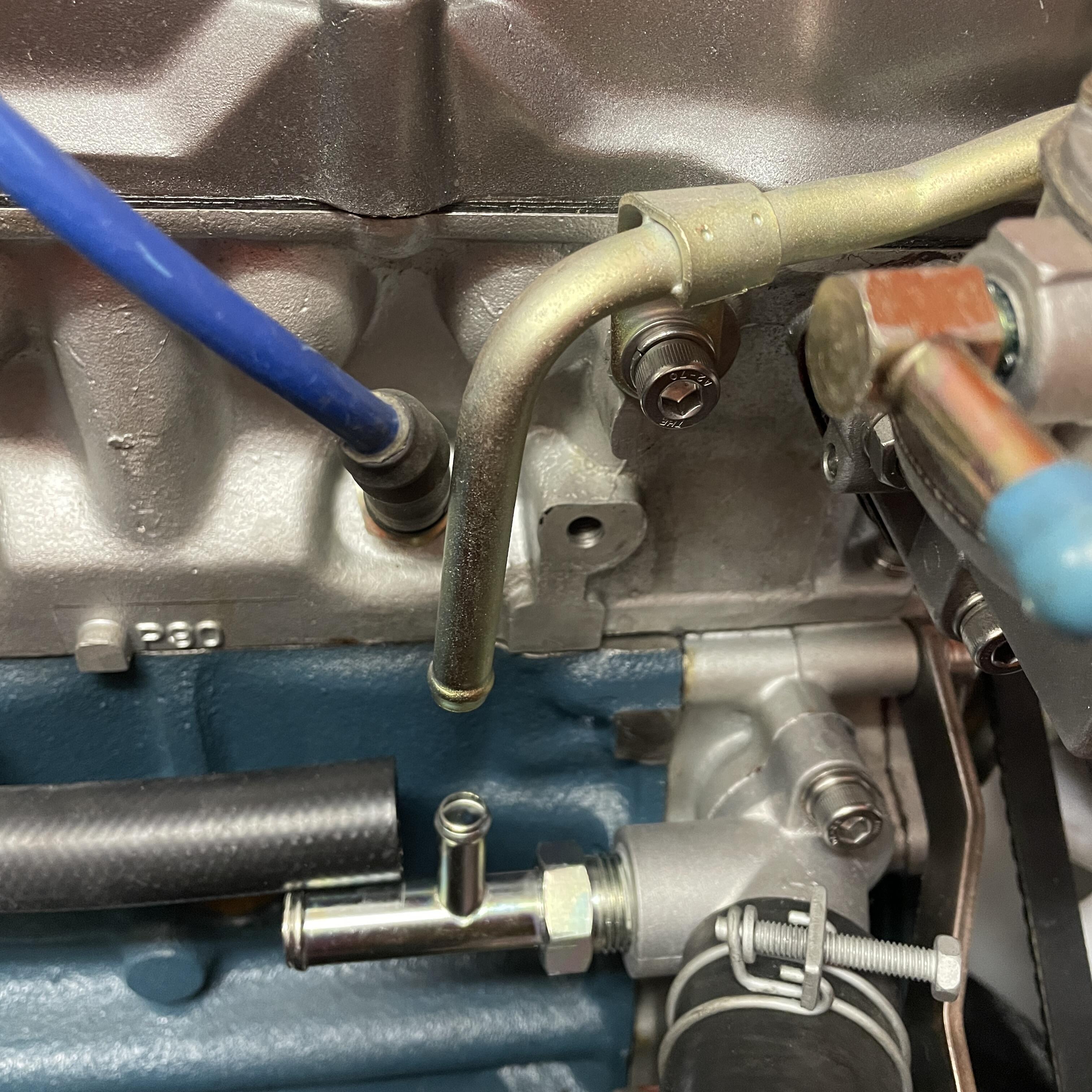
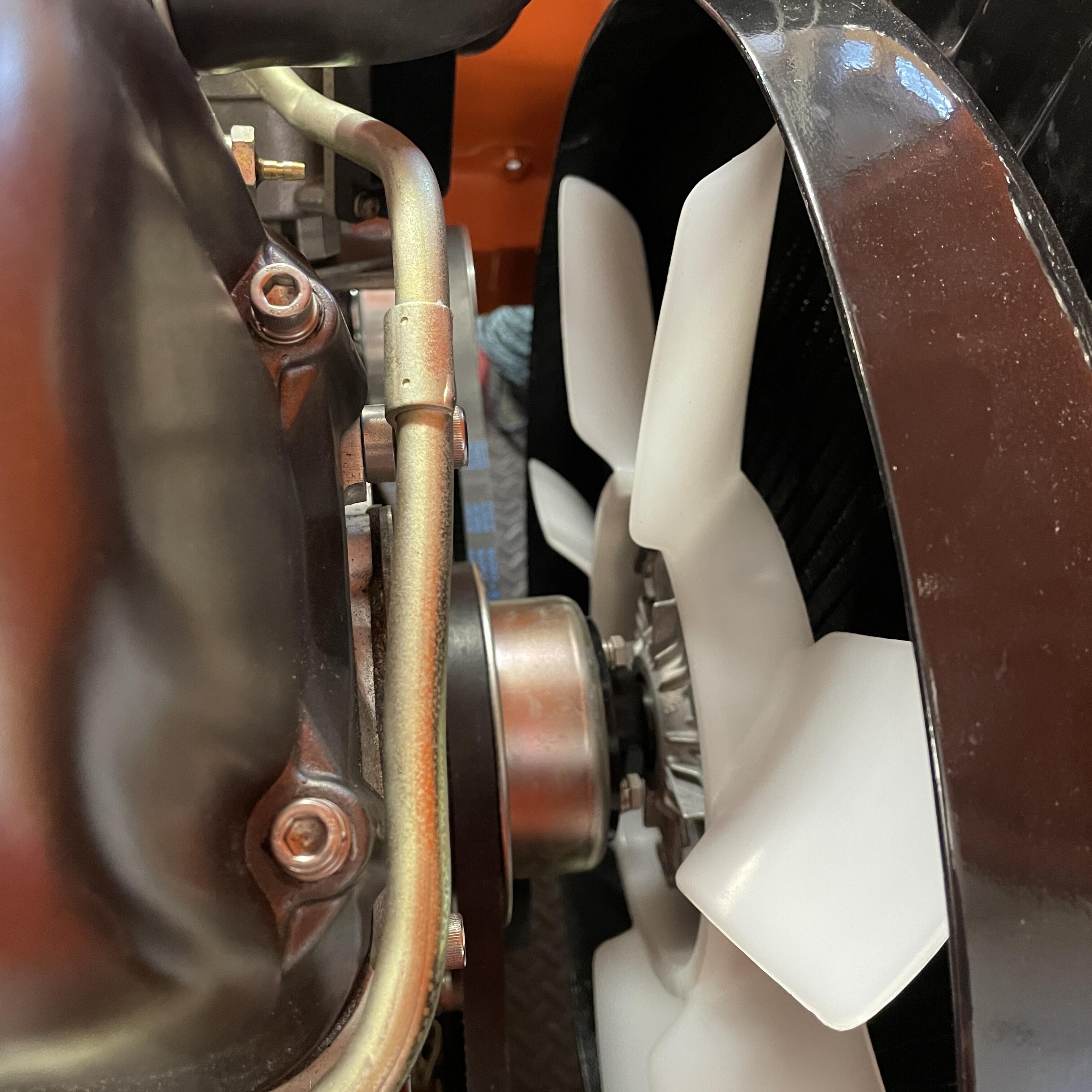
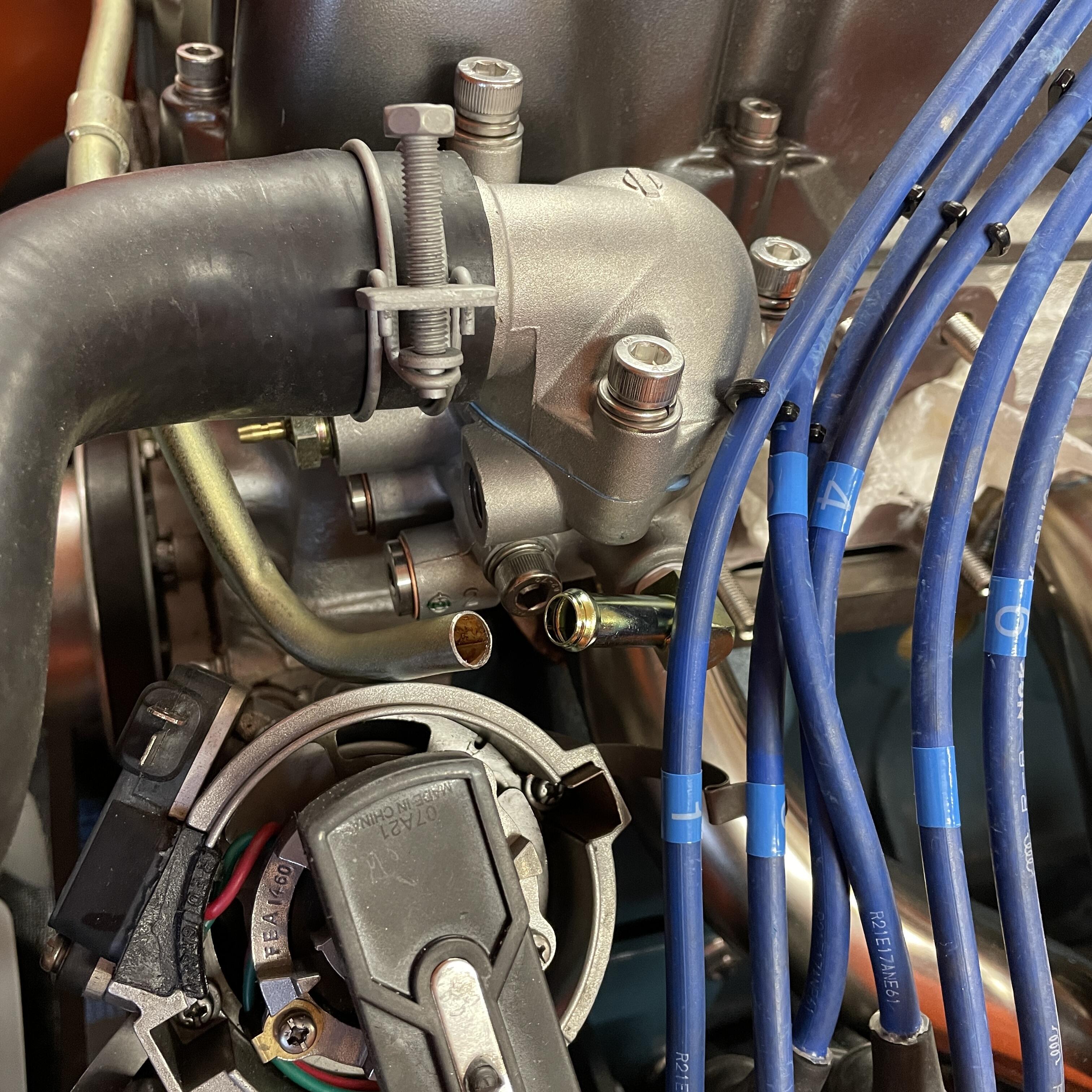
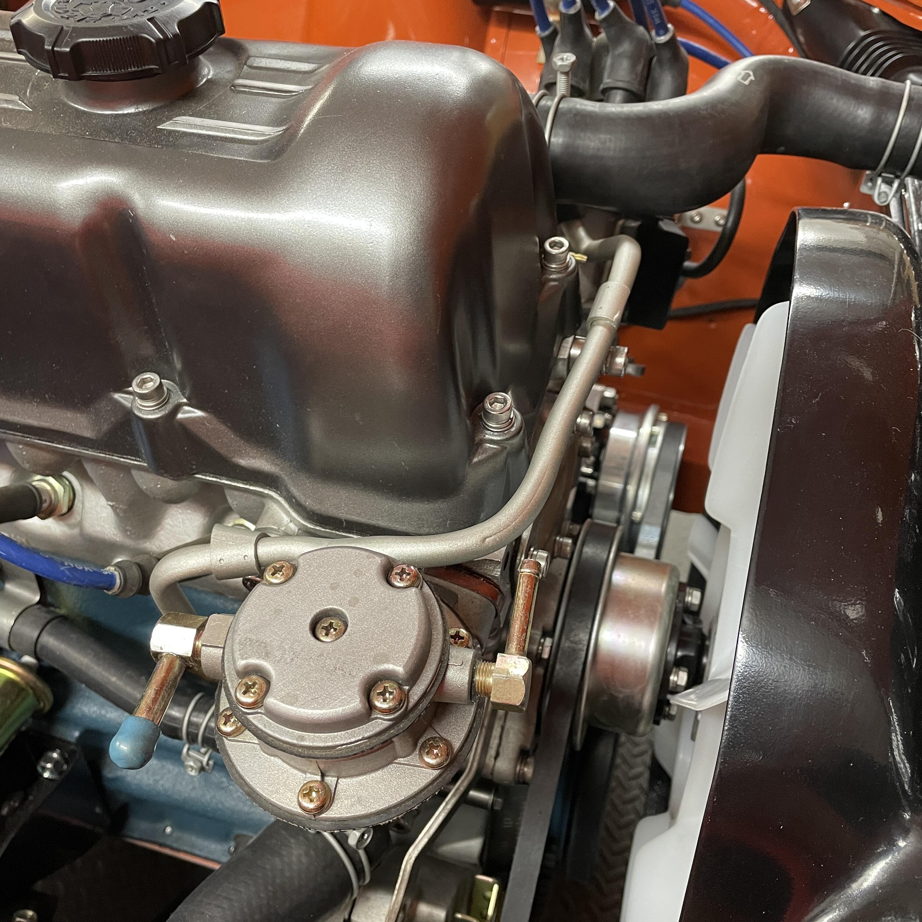
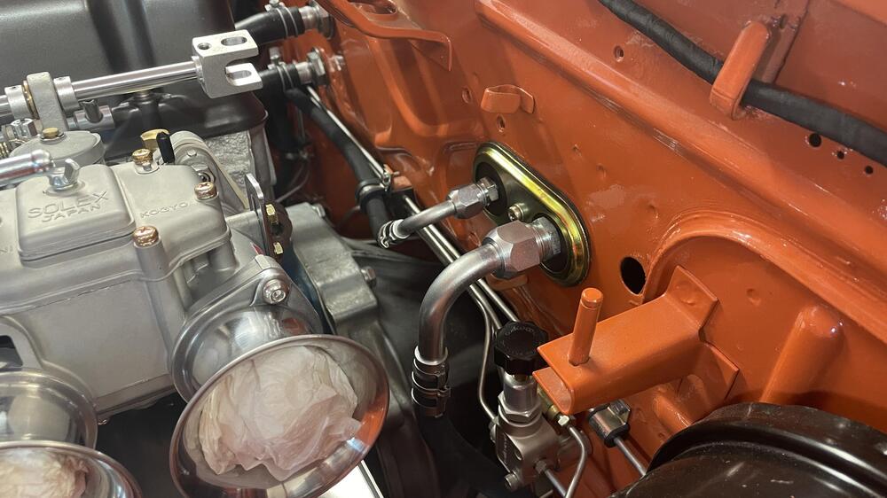
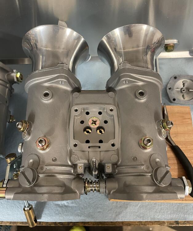
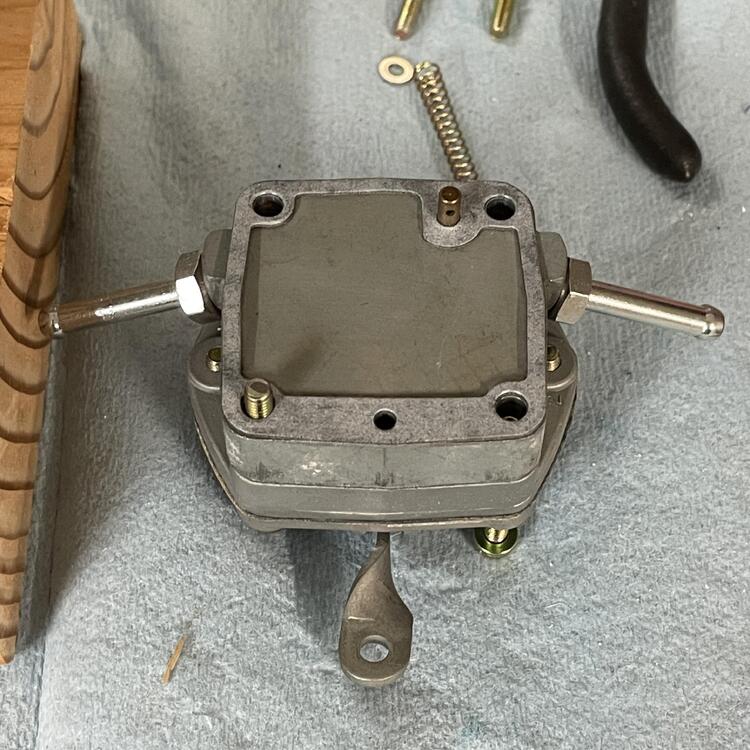
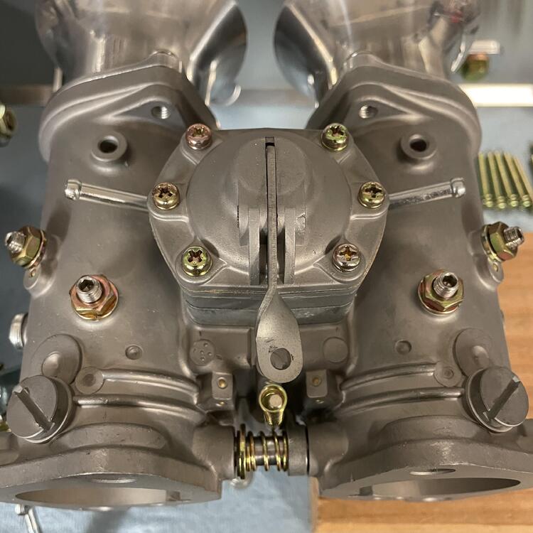
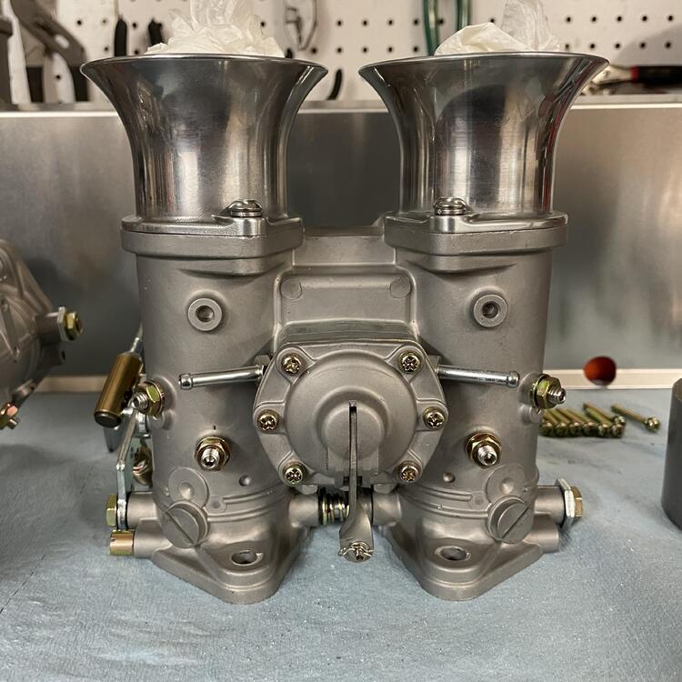
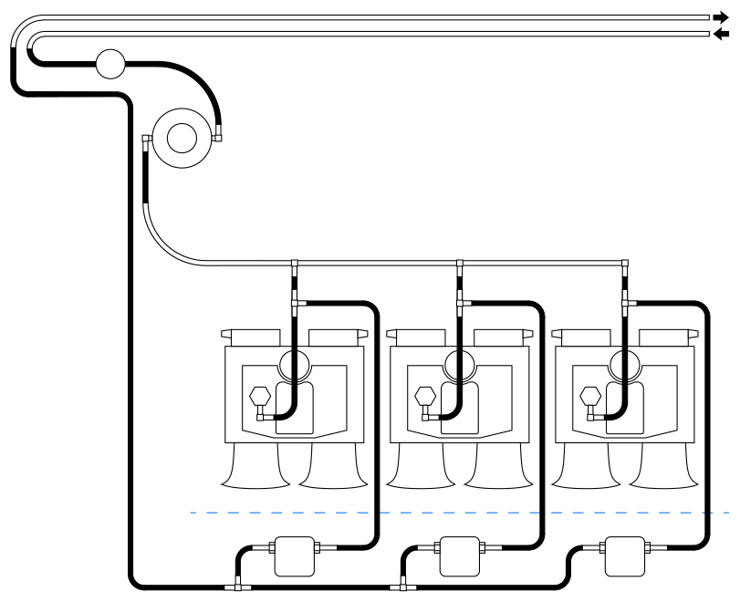
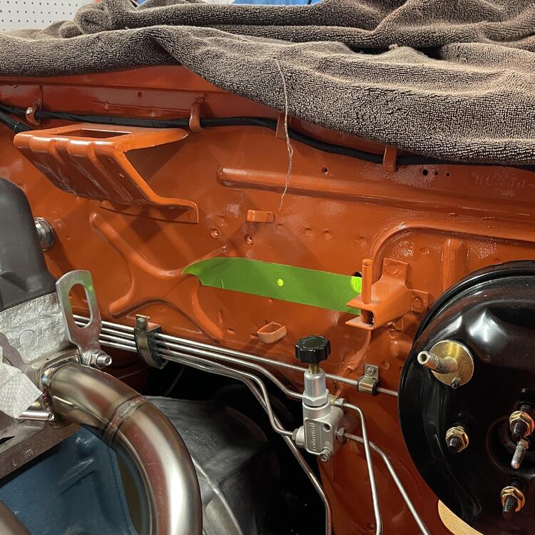
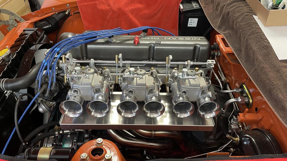
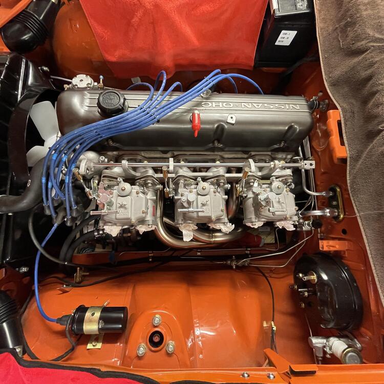
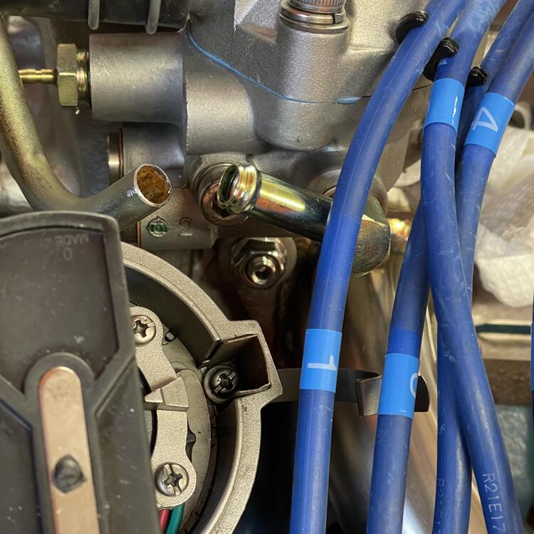
When I say back pressure regulator, I mean a regulator that controls pressure before it in the sequence rather than after it. Unless I am mistaken, a bypass regulator controls the pressure after it by relieving the excess pressure through a second port (the bypass), but the pressure before the regulator would still be unregulated. I’m using the Datsun Competition rail. Here are some photos from my build thread to help clarify:


-
Back Pressure Regulator Recommendations?
Matthew Abate replied to Matthew Abate's topic in Triple Mikuni and Webers
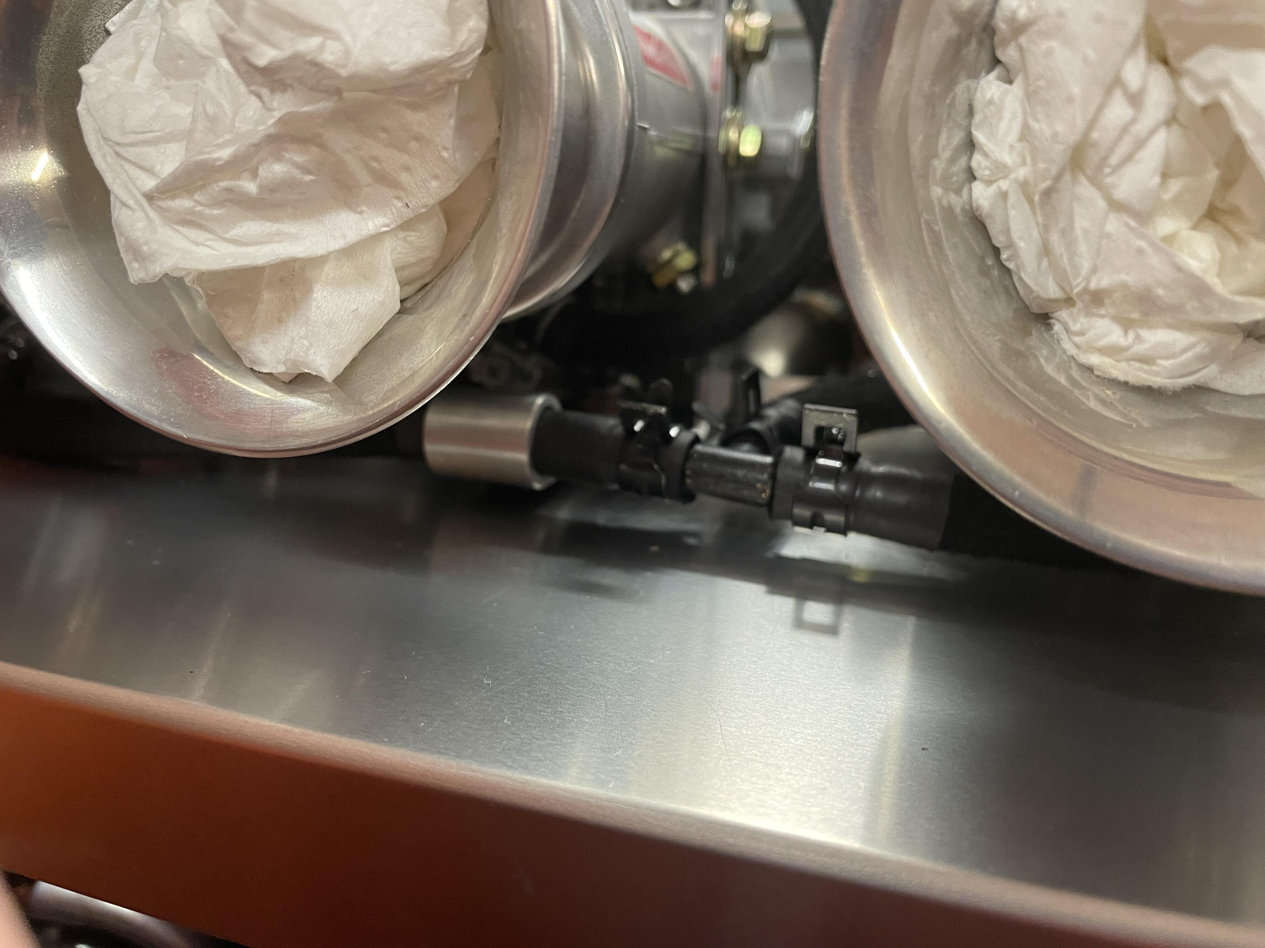
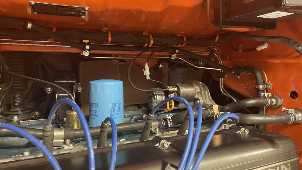
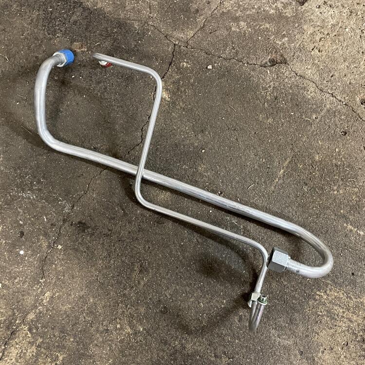
I’ve been thinking about using the cooling bodies to do that, but I don’t know if the fuel flows through them continuously or only under certain conditions. To do this I would have the fuel go to the carbs in a deadhead configuration and tap the end of the fuel rail for a fitting the same size as the cooling body inputs. A gauge could go here. Then the only thing to figure out is how to run the hose from the front cooling body to the return line. -
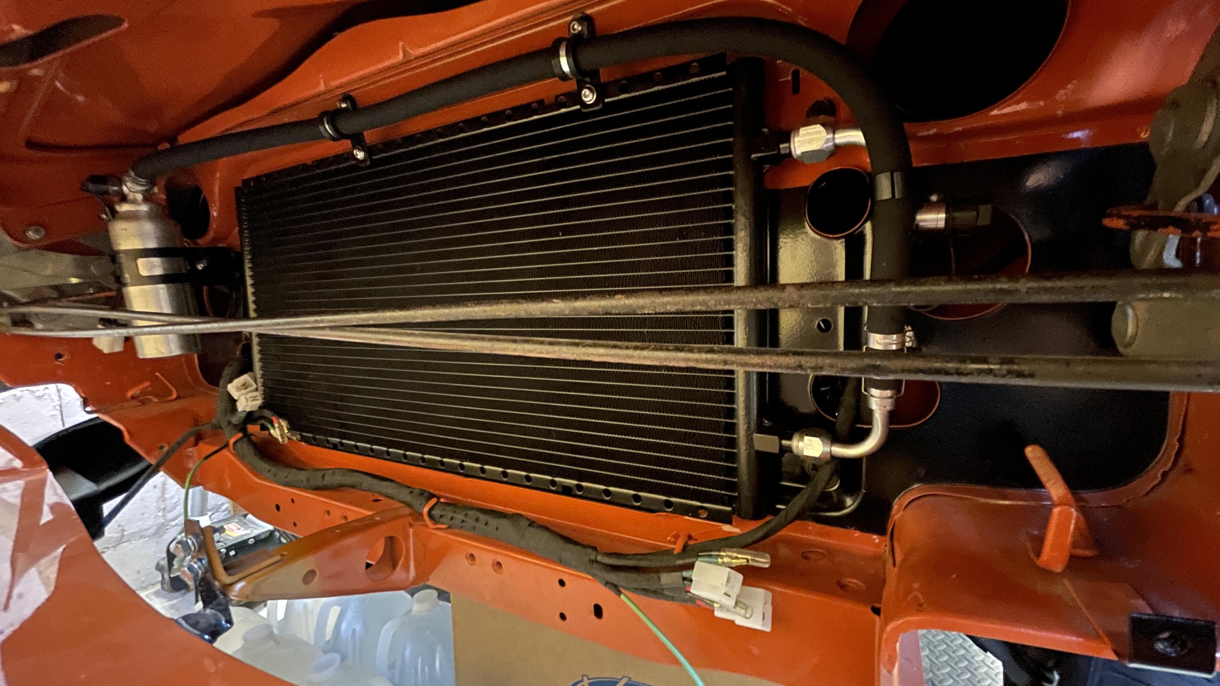
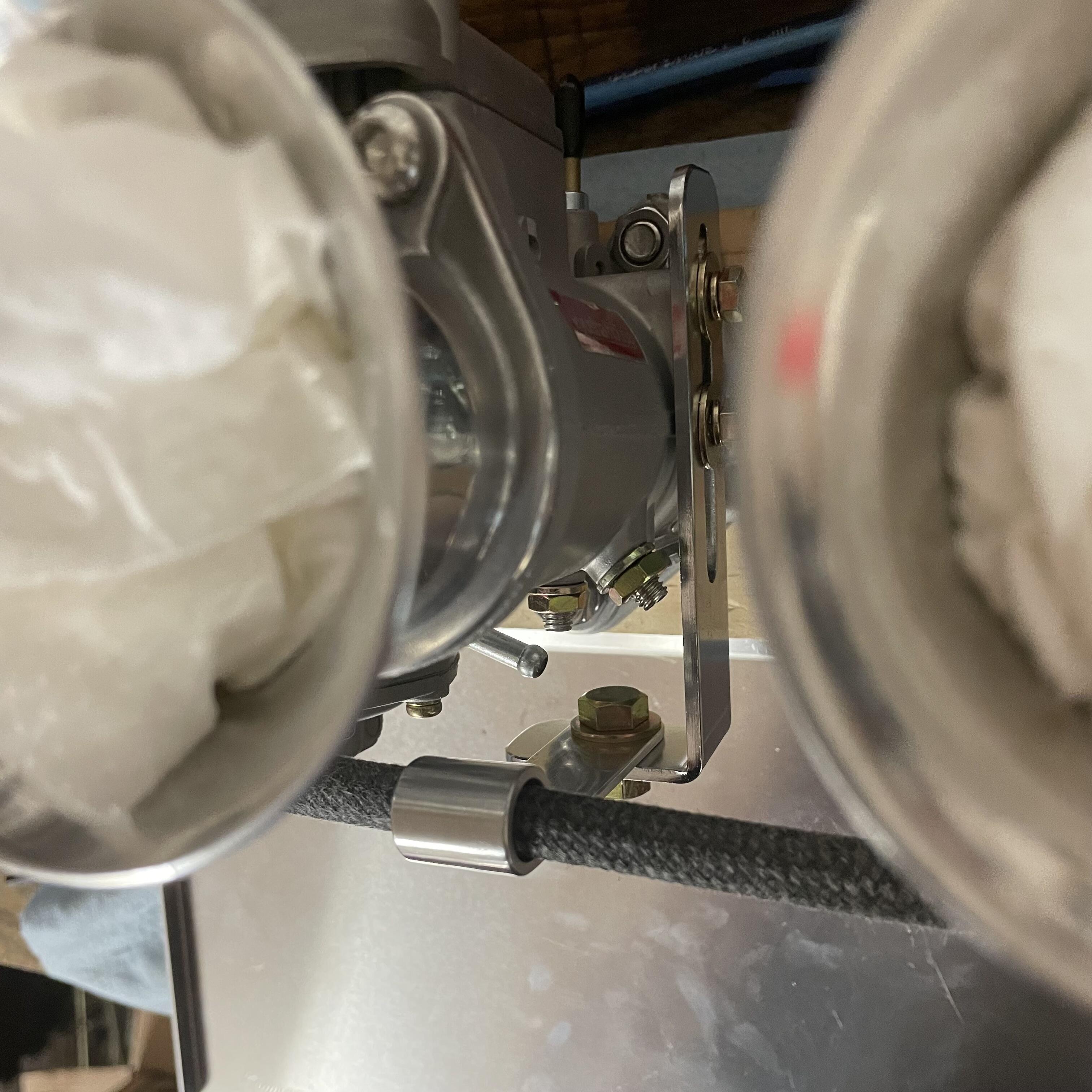
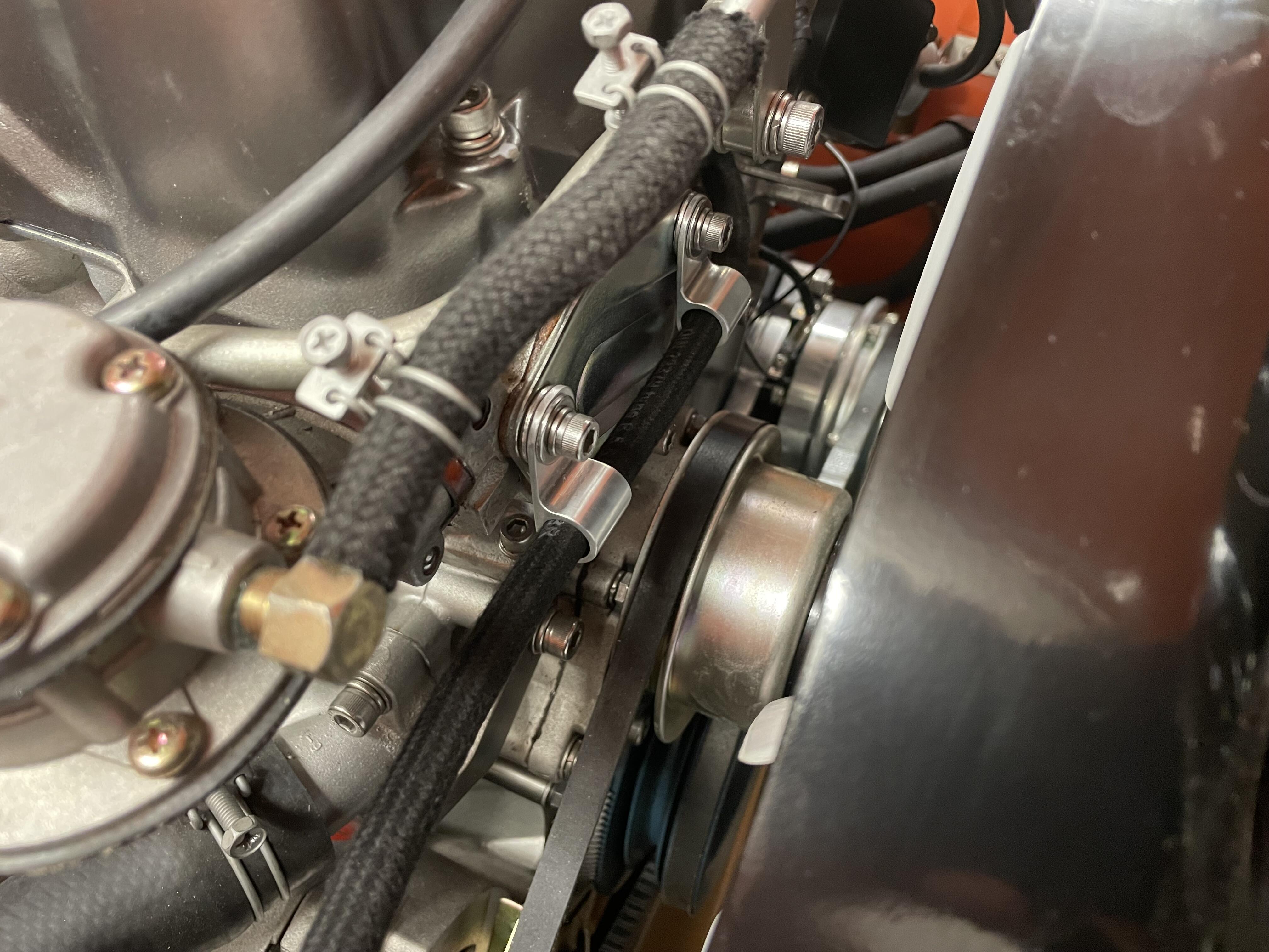
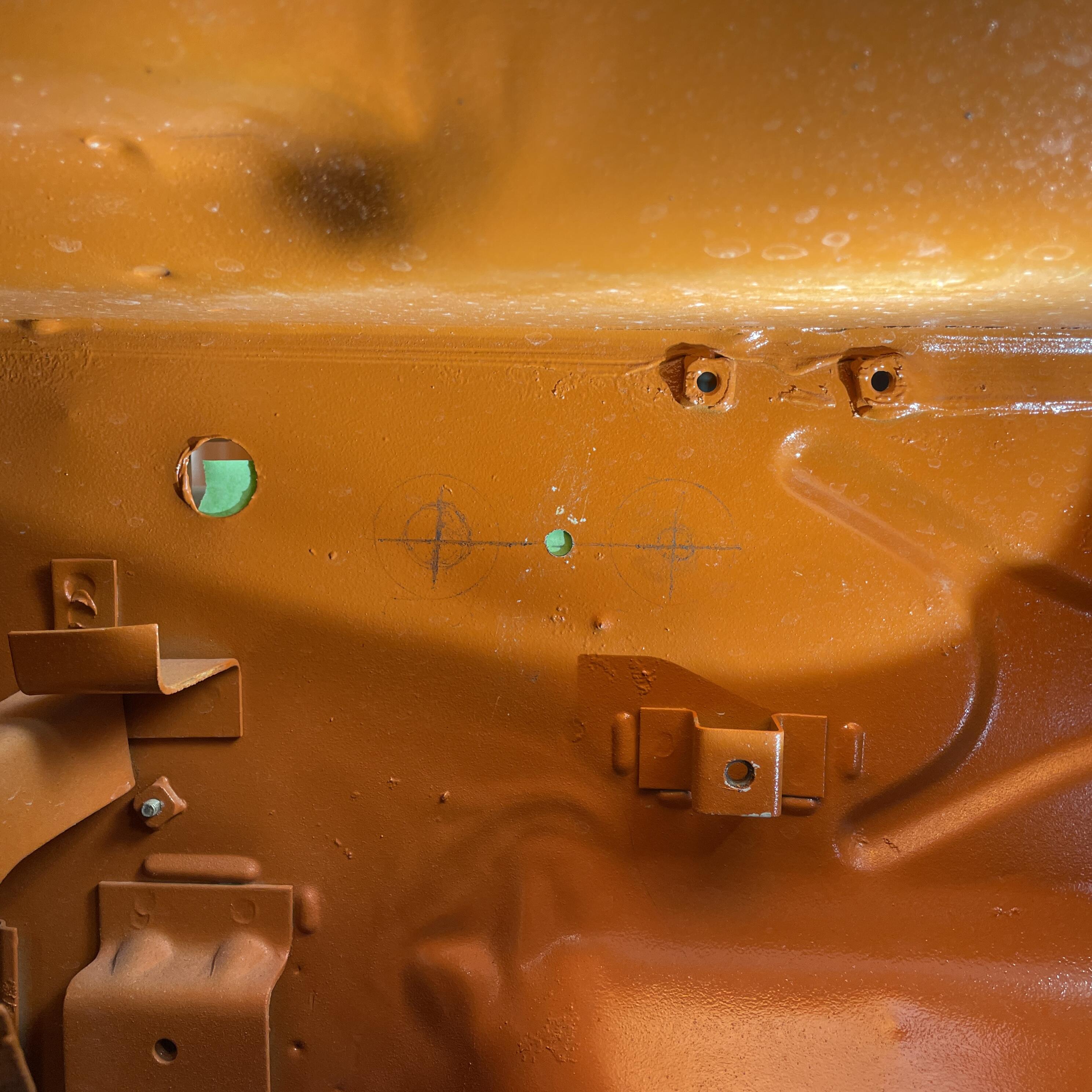
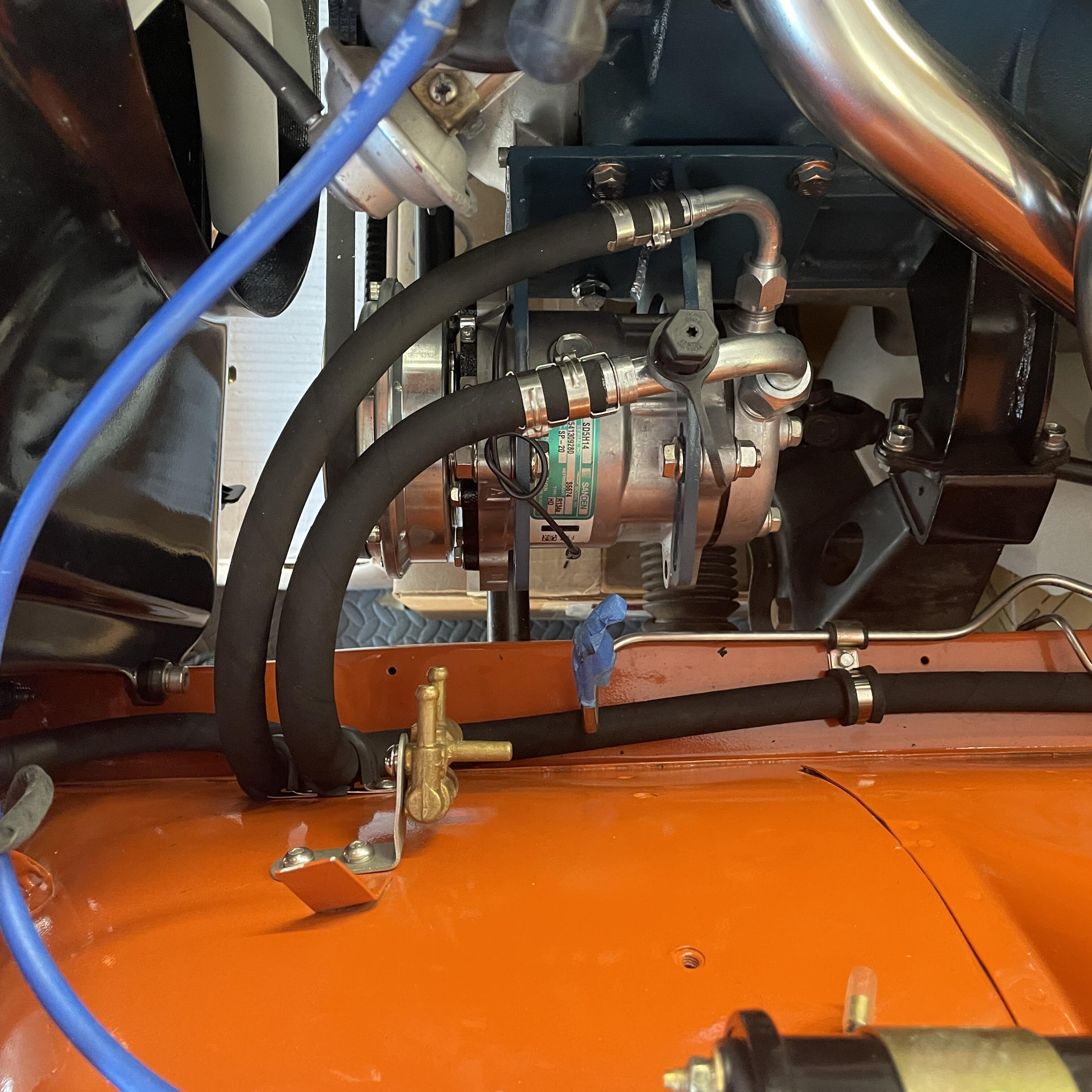
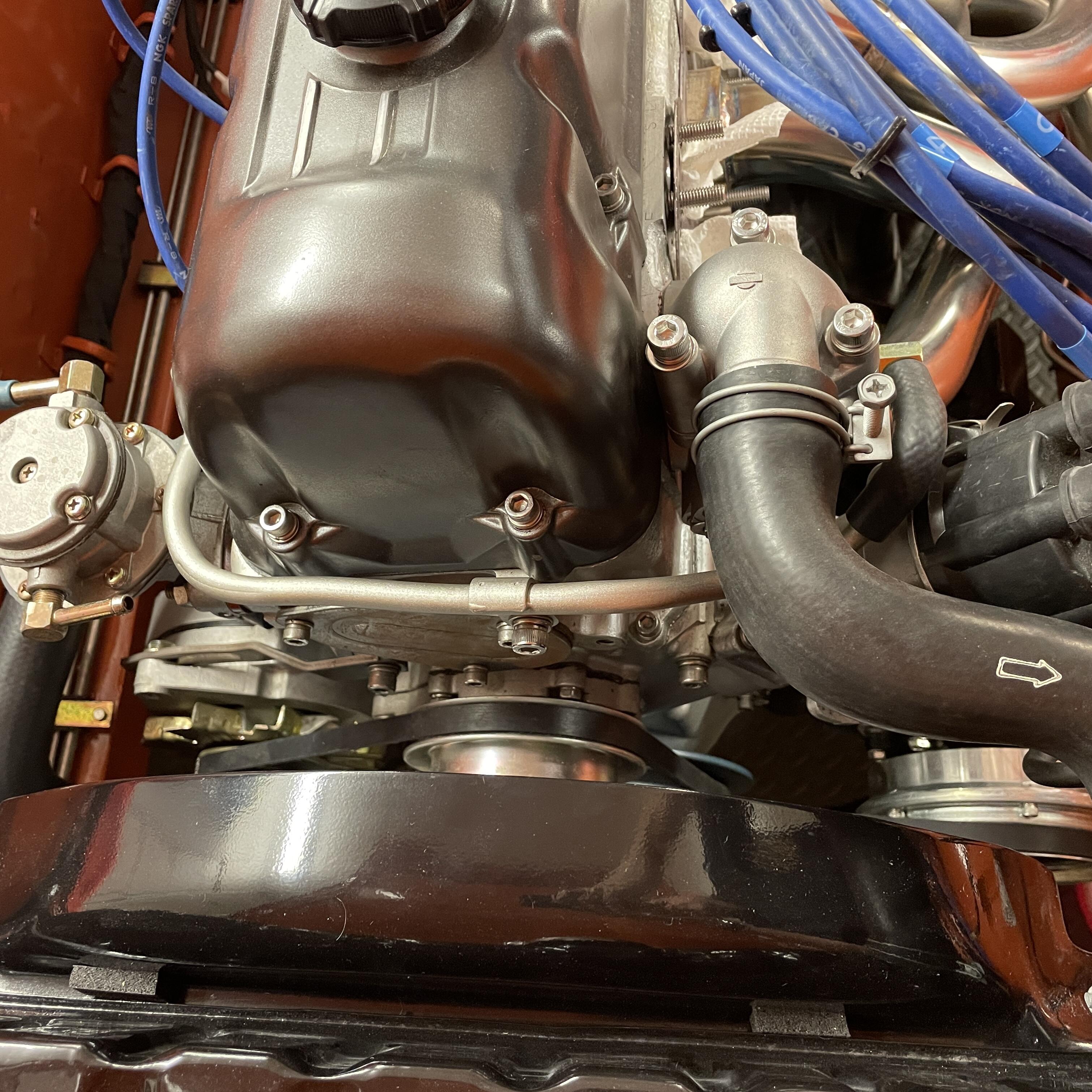
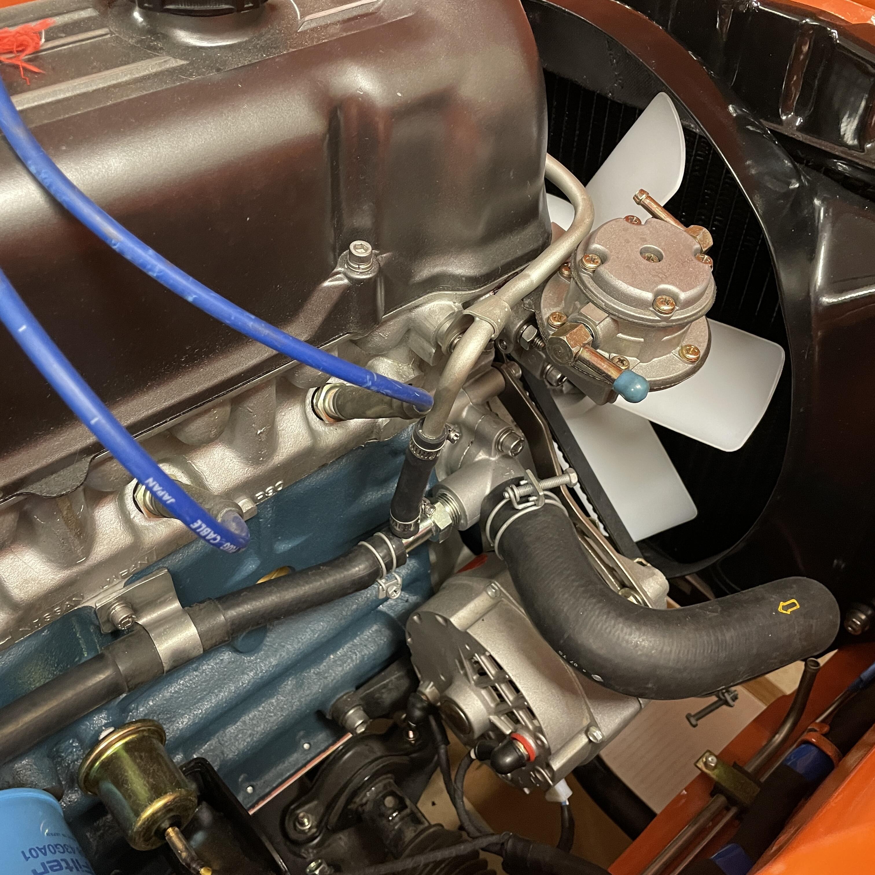
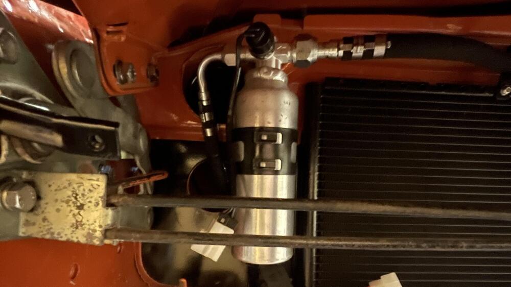
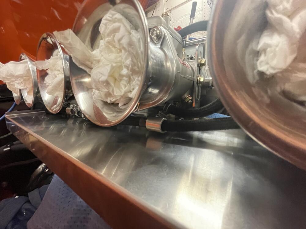
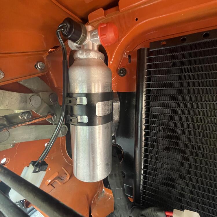
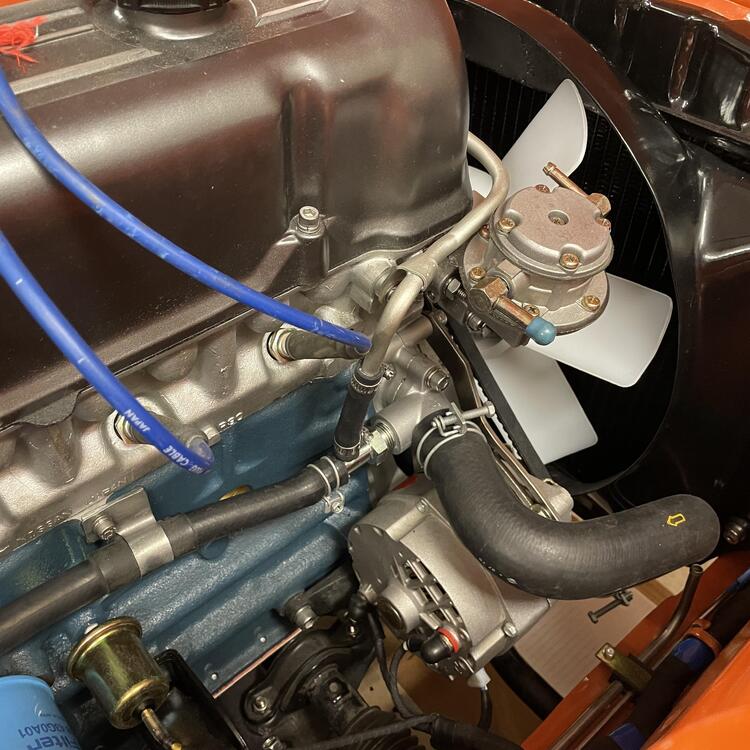
I am trying to retain my mechanical fuel pump while also using triple Mikuni PHH44s, and ALSO utilize the return line. I’ve been reading that it would be advisable to use a fuel pressure regulator (and also a fuel cooler) but I have only been able to find FPRs that go before the carburetors in the fuel circuit. I can’t do this and keep the mechanical fuel pump do to space limitations (see here)and a lack of good mounting options. I have seen several mentions of putting the FPR after the carburetors, mostly in threads about keeping the return line. In order to do that I would need a back pressure regulator, but I haven’t found one that works with gasoline or is intended to be used with carburetors (under 5 PSI). Is anyone aware of one out there? Ideally it would be adjustable down to 2 PSI to dial it in for the Mikunis. I emailed Aeromotive about their Ultra-low Preassure FPR for carburetors and whether they have something that would work for my application, but they were not able to solve it. At best I could try to use their X1 carburetor FPR, which is a bypass-style regulator adjustable from 3-20, but they didn’t sound confident about that. Maybe I’m not asking the right question or don’t understand how this works well enough. Any help is much appreciated!
-
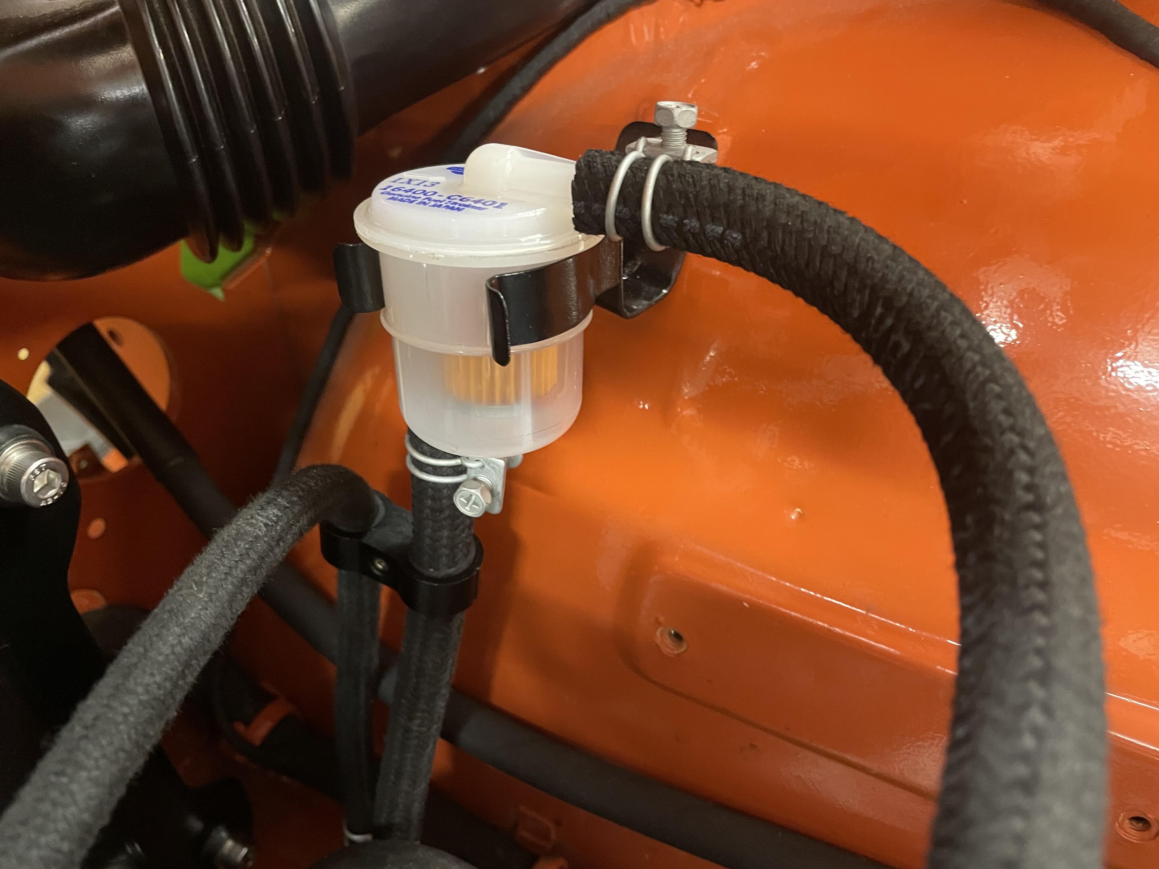
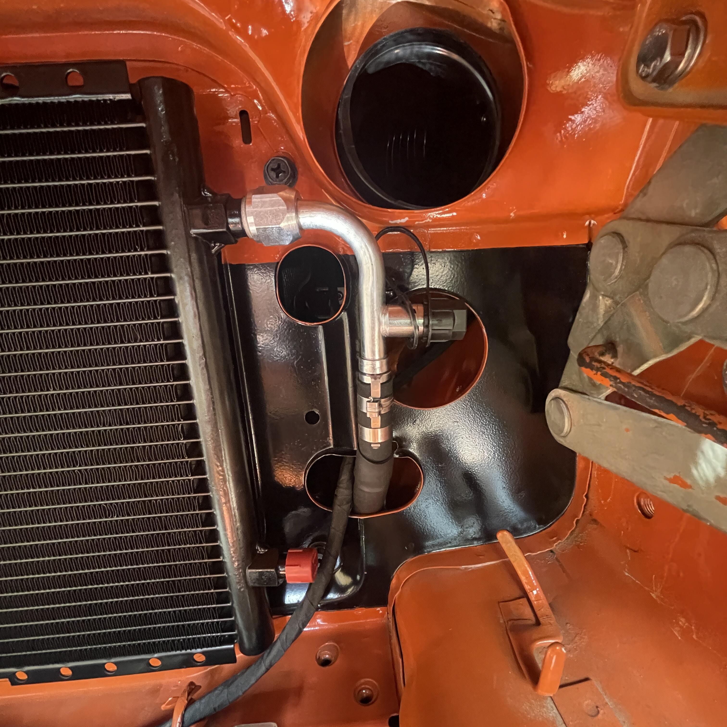
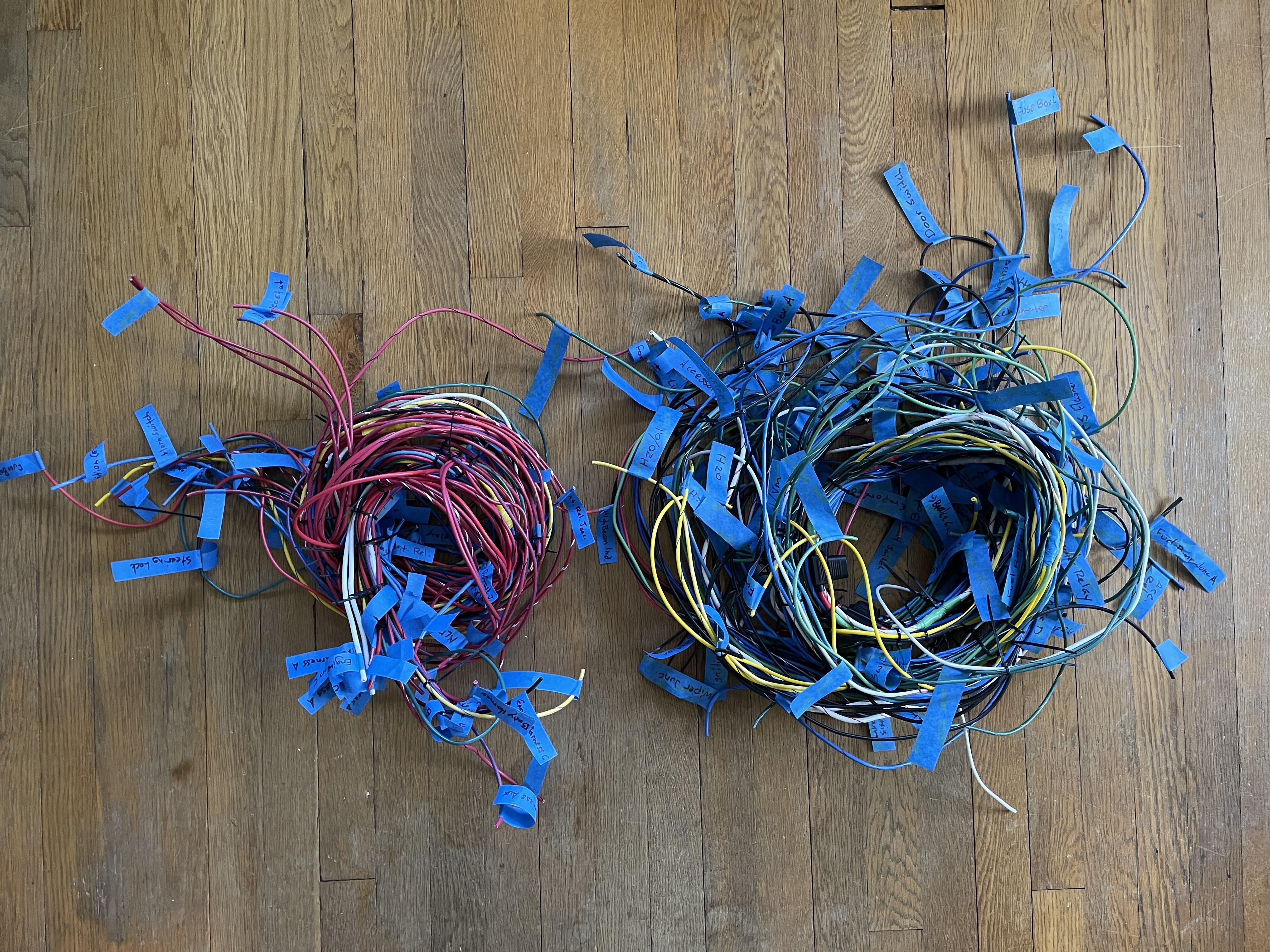
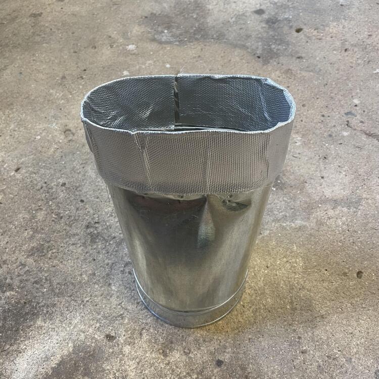
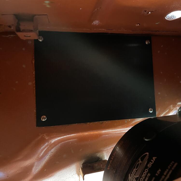
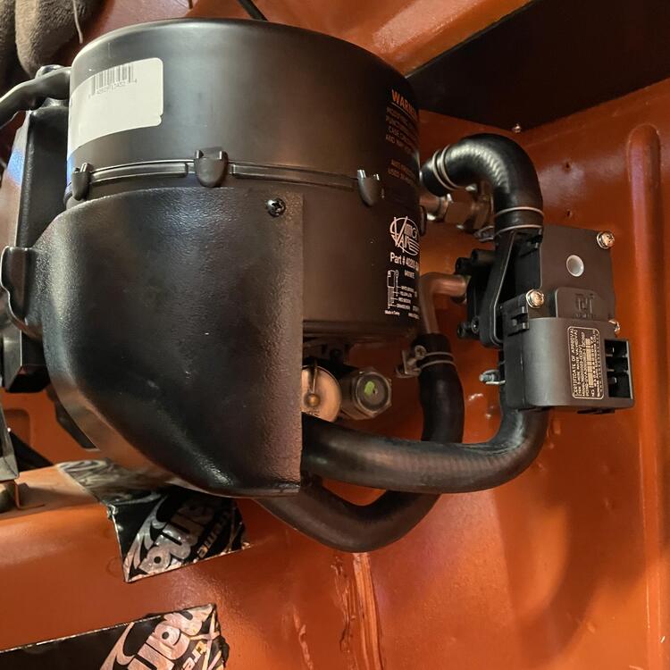
Okay. Time for an update. I’ve done a bunch of random stuff, mostly on the dash wiring, but here and there with other stuff… First, I e been working on the AC lines. I went around and around in this one, looking into making stainless line, then buying the Godzilla kit, and then buying Vintage Air hard lines. I ended up settling on a mix of hardlines and Aeroquip E-Z Clip hoses. ”Prototypes (i.e. failed attempts): AC hard lines for inside the cabin are in, but ugly. This one was a pain. I went through several pieces until I got the lengths and bends right, and even these aren’t wonderful, so I’ll redo them one more time. I opted for Vintage Air U-Bend-Em aluminum hard lines because stainless was going to be far too expensive and the hose options I investigated didn’t quite cut it. These fit okay, but you can see the -06 line is too long and I had to cram it in. I got another so I could make them fit better. It’s important because right now they are pulling on the lines they connect to in the engine bay. The firewall insulator is OEM from eBay. It’s in pretty good shape considering its age. • • • I’ve also been scrounging up my relays, which I talk about in my wiring thread. The fun one to find was the seatbelt warning buzzer and the three wire door switch, but I was able to find them after a lot of direct messaging. I’m not 100% certain all of these relays are good (still testing), but I cleaned up the best looking pieces from my pile and assembled them a few weeks ago. • • • The wires for the dash harnesses are all cut, spliced, and zip tied, so the next step is test fitting them in the dashboard and marking where they will get cut for the terminals. I won’t be wrapping these until I know everything works, so that’s a ways off. They look like a mess here, but they’re simpler than they could have been. They’re pretty heavily modified, with the stereo and antenna deleted and add provisions for various new components like footwell lights and USB-C plugs. All of the splicing and positioning has been checked and verified against the diagram I made as well as the original harnesses. The wire is heavier gauge and marine insulation (yes, overkill). Will it fit? We will find out. Why? Burnt wires, the PO used a harness for an automatic in a manual car, I wanted to incorporate the fuel harnesses into the dash harness, and to make it fresh. That right there is over a year in the making. Glad it’s over. • • • Now on to the engine bay. Carb-side AC lines are done! The hose for the other side is in the mail, so I’ll knock that out soon. You can see the prototype of the hard line in the photo above. There are two problems with it: the max length is 72 inches, which is about two inches too short to get a nice clean routing, and about six inches too short to tuck it away and make it discreet; and the end is just slightly wrong for the R32 Skyline AC drier/receiver in the last photo in this sequence. I like that drier too much to switch it out and I’m uneasy about modifying the end of the line and potentially not getting a tight seal, so hoses it is! The hose for the E-Z Clip system bends tighter than regular AC hose, but it doesn’t bend quite as tightly as I had hoped (it’s rated at a 2” radius for the -08 hose) so it gets weird in a couple of places, and I’m still unsure if these Danfoss E-Z Clip fittings are going to be air tight. We will find out when I try to charge the system. You can barely make out where I sleeved the hose at points where it might rub on something. I used three layers of heavy duty shrink wrap for this and I think it looks almost like it’s supposed to be there. All I need to do with these, though, is add a hose separator that is the right size to keep that -08 hose from flexing too much. I have two of them in the mail to me now. • • • I installed the fuel rail for the triples the other day. This was surprisingly involved. I thought I would just slap it on and call it done, but there were several barriers; nothing crazy, but time consuming and requiring thinking it through. I had intended to use the empty M10x1.0 holes that are next to the M8 manifold mounting holes, but the rail brackets aren’t drilled for that, and the manifold nuts are too close. I tried a bunch of different workarounds but in the end it was easier to use the manifold studs as the mounting points. To do that I had to use longer studs, which meant grinding some relief into the manifold. I REALLY didn’t want to do that, but I caved and broke out the Dremel tool. Was I paranoid I was going to pierce the runners? 100% But I didn’t. I switched to hand files after a while just to make sure I wasn’t going through it too fast. All those years of model making have paid off in writes on this car. So once that was done I put the thing together and realized these rails are meant to go with electric fuel pumps. I have a NOS mechanical pump on this car and I worked too damned hard to find it to go dumping it for this, so the rail got a trim and beads rolled on the end. Looks like it’s supposed to be like that now. After that I just had to tweak the bends to make sure it cleared everything and it’s good to go. Now to figure out the fuel hoses and find a fuel filter bracket. • • • So the big question now is… HOW TO ROUTE THE FUEL LINES? I would like to use the return line, so I would need to send the fuel back to the other side somehow. Right now I am leaning toward installing my Mikuni cooling bodies and running a line across the front of the engine under the coolant line, but I’m trying to think of something more elegant.


-
Godzilla Raceworks Vintage Air Conversion Hoses
Matthew Abate replied to Matthew Abate's topic in Open Chit Chat
I did a test fit but will probably go a different direction. It’s well made and would be great except that it gets too close to my headers. After discussing it with them they told me it’s designed to work around the stock exhaust manifold, which doesn’t get as close. I think it’s a good option for anyone with that setup and will probably be selling the kit I have. It’s been too long to return it. -
1973 240z Custom Wiring From Scratch
Matthew Abate replied to Matthew Abate's topic in Build Threads
I’m not 100% certain all of these relays are good (still testing), but I cleaned up the best looking pieces from my pile assembled them today. 🤞🏻

-
1973 240z Custom Wiring From Scratch
Matthew Abate replied to Matthew Abate's topic in Build Threads
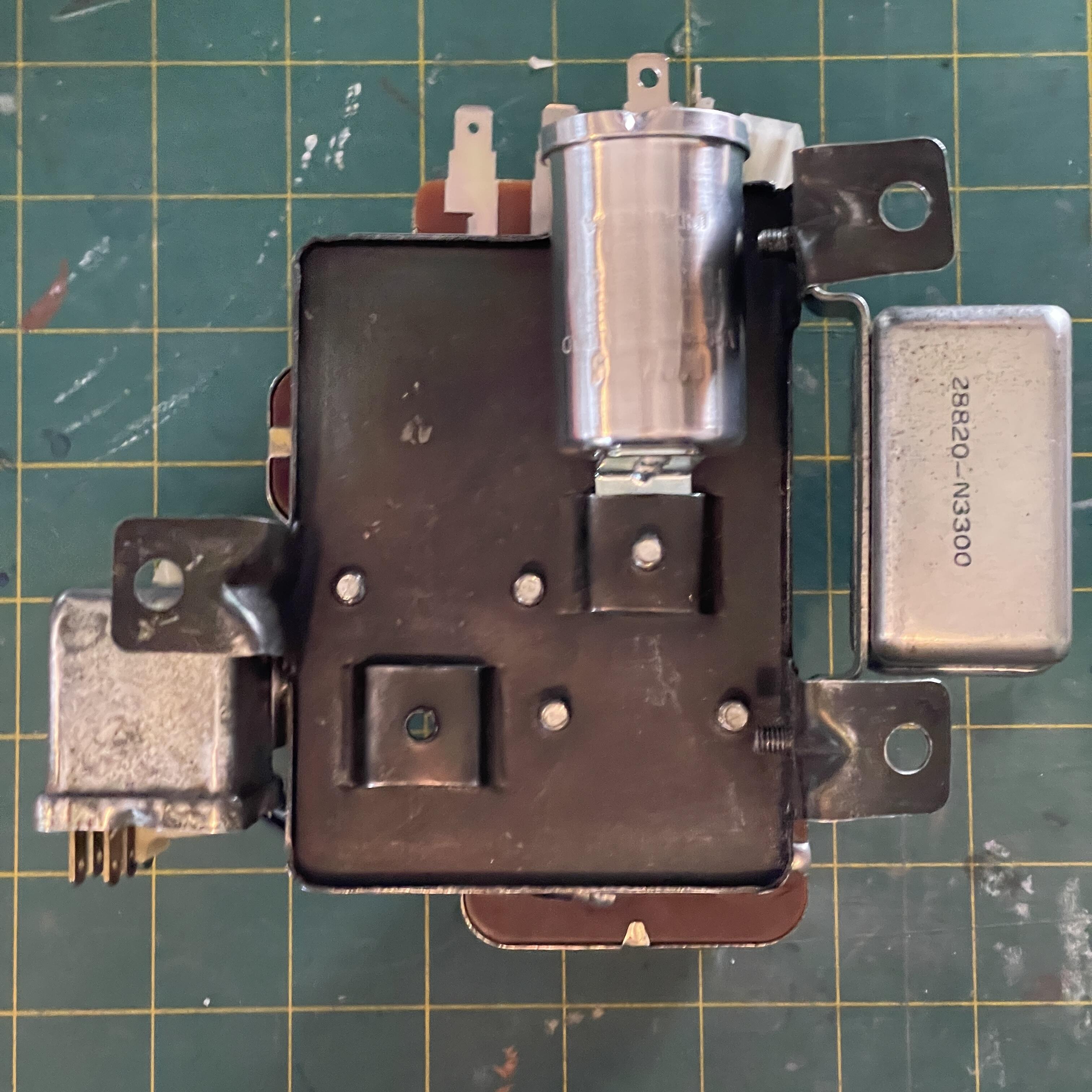
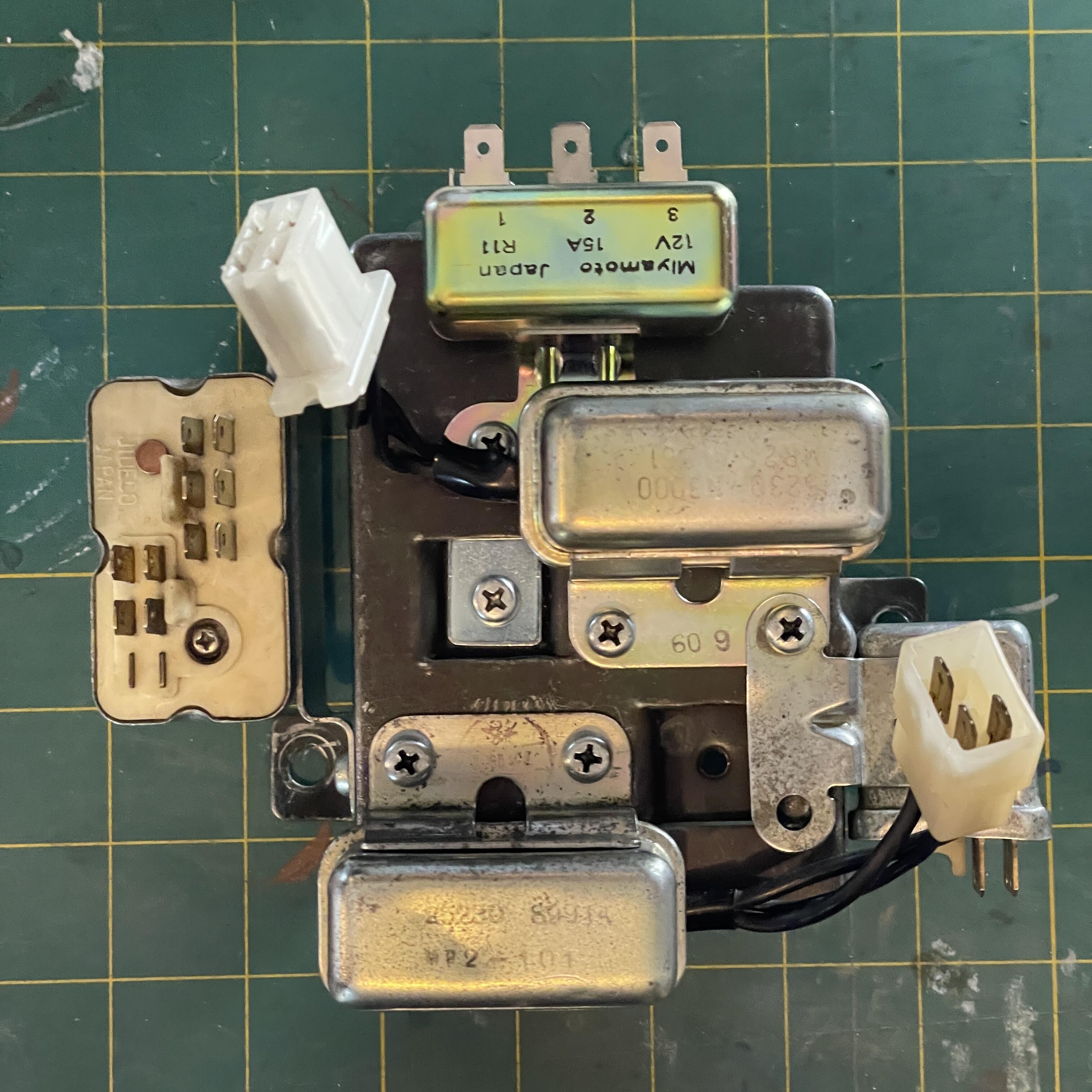
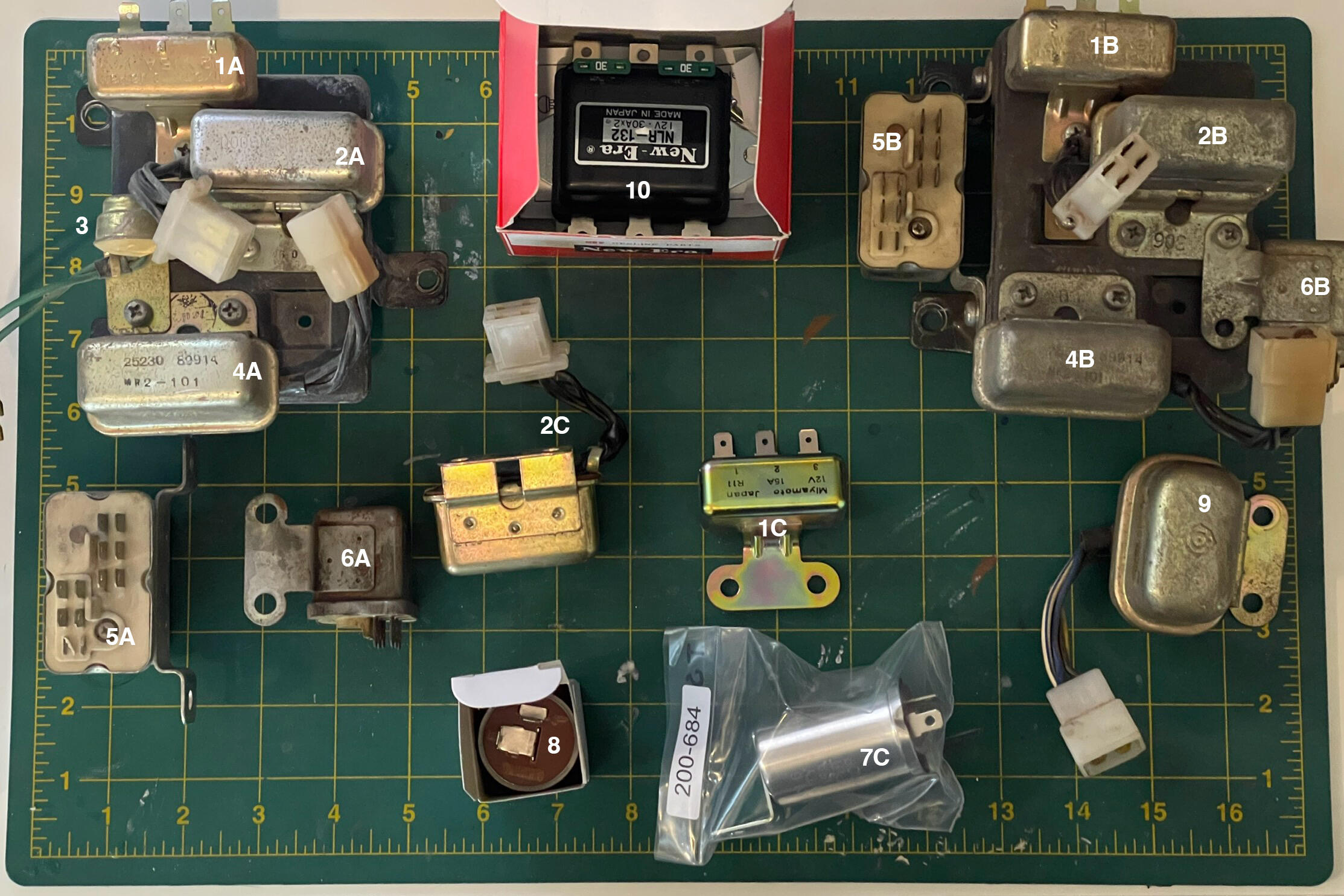
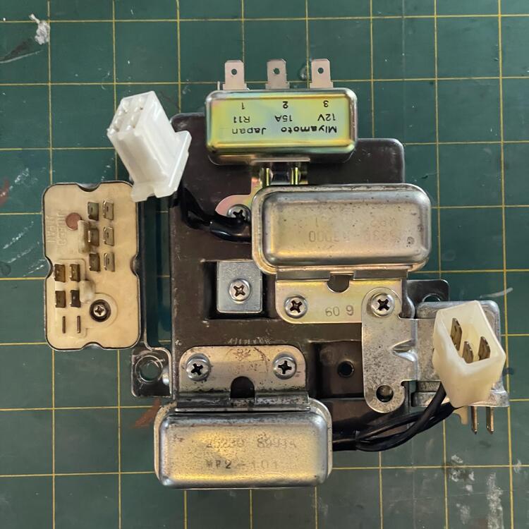
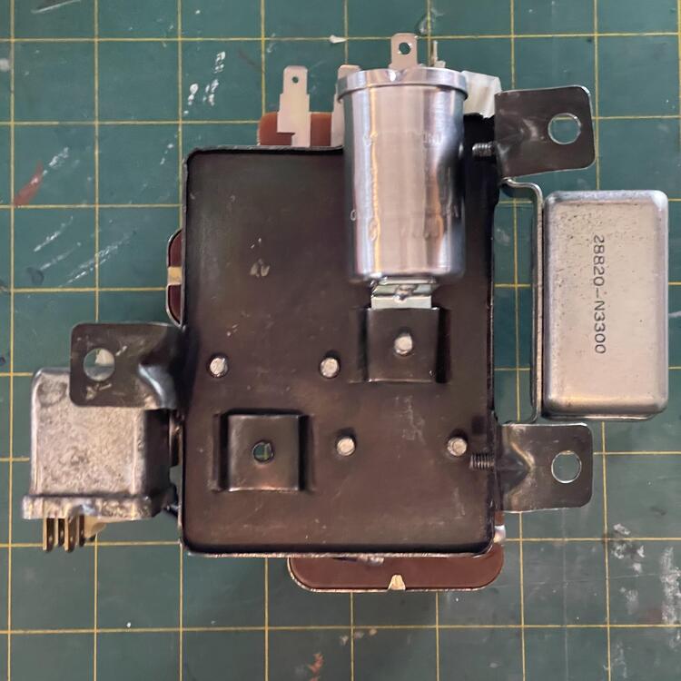
Can you guys help me figure out which relays I’m missing? This is what I’ve found in my boxes: 1 - Horn Relay 26320-89905 2 - Defroster Relay 25230-N3000 3 - Thermostat Switch 22110-E8000 4 - Air Conditioner Relay 25230-89914 (the internet also says heater) 5 - Intermittent Relay 28820-N3300 6 - Fuel Pump Relay 25230-89915 (the internet also says headlight) 7 - Hazard Flasher (A & B not shown) 8 - Turn Signal Flasher 9 - Fuel Pump Relay 25235-P0101 (the internet also says fuse panel voltage regulator; I’ve seen a different relay with the same number) 10 - NLR-132 will be used for headlights I have a key-warning buzzer coming in the mail for when the door is open and the key is in the on position. And I will not be using the Throttle Opener Relay that goes on the engine side of the firewall. I have a 4-pin connector on the front fuel pump harness that I figure goes to a relay if you have an electric front fuel pump. I’m keeping my mechanical one for now because it is NOS. If it gives me issues I’ll switch over. I am assuming not having this connected doesn’t mess with anything since that was stashed away with blue tape from the factory. I’ve also seen things about a “heater / choke” relay, but don’t see anything for that in the diagram. I found a relay numbered 25235-P0110 on a Datsun 1200 wiki, but can’t find anything for Z cars. —- I think I’m all set. I don’t think I need to retain the thermostat switch (#3). I think this might be unique to 1973-4 automatics. Can anyone identify that thing or think of anything I might be missing?
-
1973 240z Custom Wiring From Scratch
Matthew Abate replied to Matthew Abate's topic in Build Threads
Anyone have a source for the key warning buzzer and 3-wire door ajar switch for a 1973 240z? I found a set but and hesitant due to price and unsure they even work. I also have a workaround but am leaning OEM for now. -
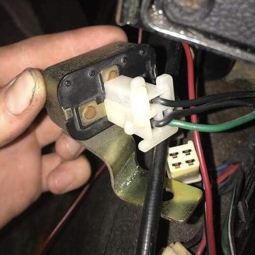
View Advert ISO Warning Buzzer & 3-Wire Door Switch - 1973 240z I am looking for a working buzzer for a 1973 240z and the 3-wire door ajar switch that makes it work with the steering lock switch. This buzzer sounds when the key is on while the door is open. The 3-wire switch completes the circuit for the buzzer if both conditions are met. See photos for examples. Preferably NOS, but nice working condition will work. Please keep your fees reasonable. I have a source for these already but am looking for them in nicer condition. Advertiser Matthew Abate Date 03/11/2024 Price Category Parts Wanted Year 1973 Model 240z
-
This advert is COMPLETED!
- WANTED
- USED
I am looking for a working buzzer for a 1973 240z and the 3-wire door ajar switch that makes it work with the steering lock switch. This buzzer sounds when the key is on while the door is open. The 3-wire switch completes the circuit for the buzzer if both conditions are met. See photos for examples. Preferably NOS, but nice working condition will work. Please keep your fees reasonable. I have a source for these already but am looking for them in nicer condition.Ask for price
- US
-
1973 240z Custom Wiring From Scratch
Matthew Abate replied to Matthew Abate's topic in Build Threads
Haven’t decided yet, but I want the option. I need to see how the LEDs perform before I commit, so if I don’t love them I would switch to H4. -
1973 240z Custom Wiring From Scratch
Matthew Abate replied to Matthew Abate's topic in Build Threads
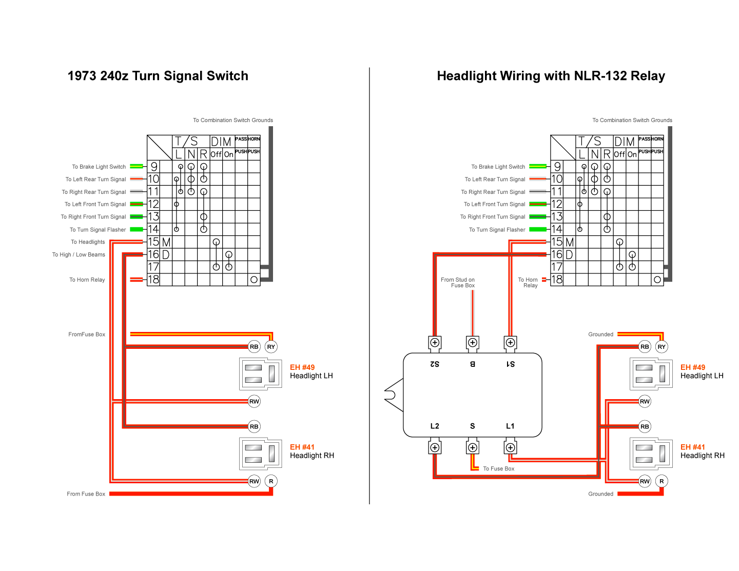
Only 10A? I’m thinking of splitting the 10 AWG white wire with a red stripe that comes from the alternator to the inside of the cabin. Originally it split off to the rear defroster and accessory relay, and terminated at the fuse box stud. The line going to the rear defroster had a 20A fuse on it originally. The Koito H4 bulbs draw 10A each, and I’m retaining the long run of wires to the headlights that is in the engine harness to cut down on stuff outside of the cabin. Mainly I’m doing this relay mod to keep the power running through the combination switch as low as possible. So what I’m thinking at the moment is splitting that 10 AWG white + red wire near the colored connectors and running it to the B post on the NLR-132. So there would still only be one wire coming off the alternator and feeding everything. -
1973 240z Custom Wiring From Scratch
Matthew Abate replied to Matthew Abate's topic in Build Threads
@SteveJ, I'm working on my dash harness and want to check with you to make sure I am wiring up this headlight relay correctly. Is it okay to run those to wires from the headlights straight to ground? Also, I could run a wire directly from the alternator to the B terminal instead of coming off the fuse box stud, right?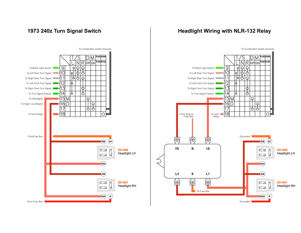
-
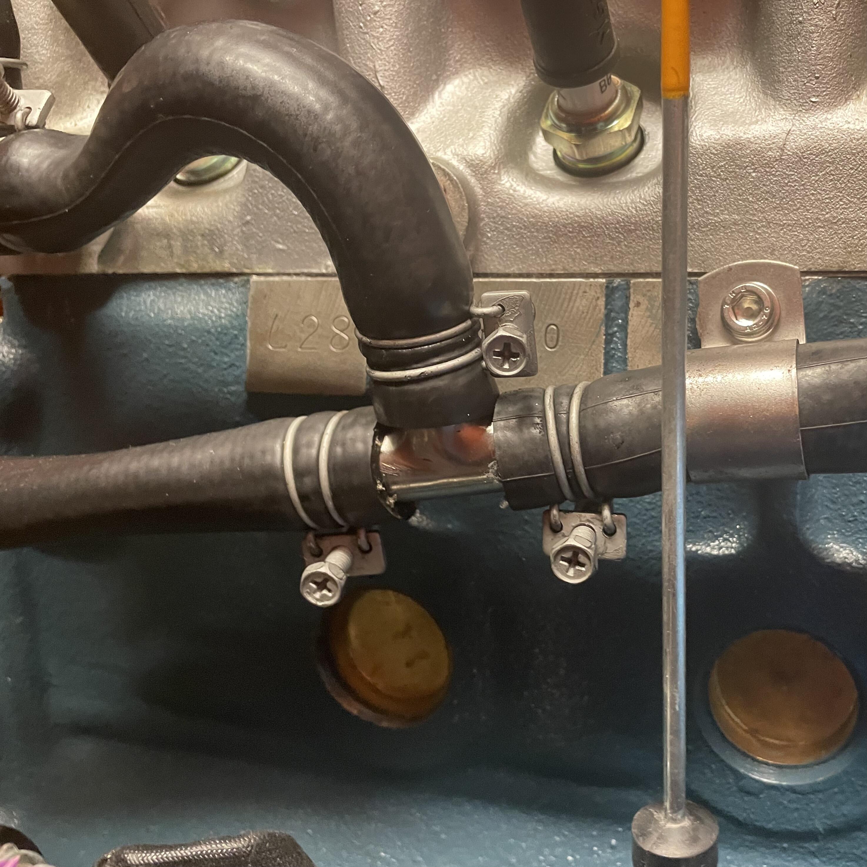
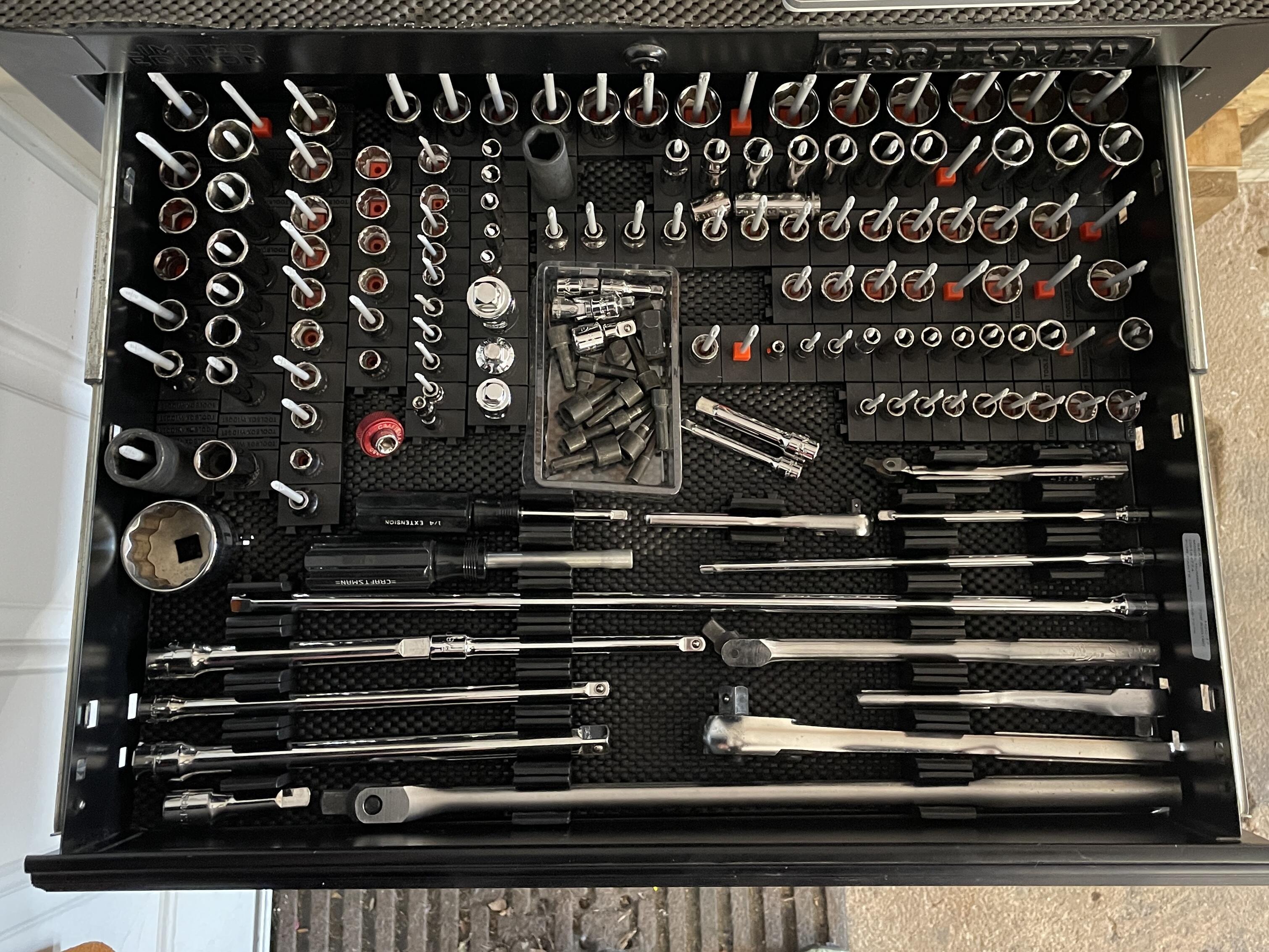
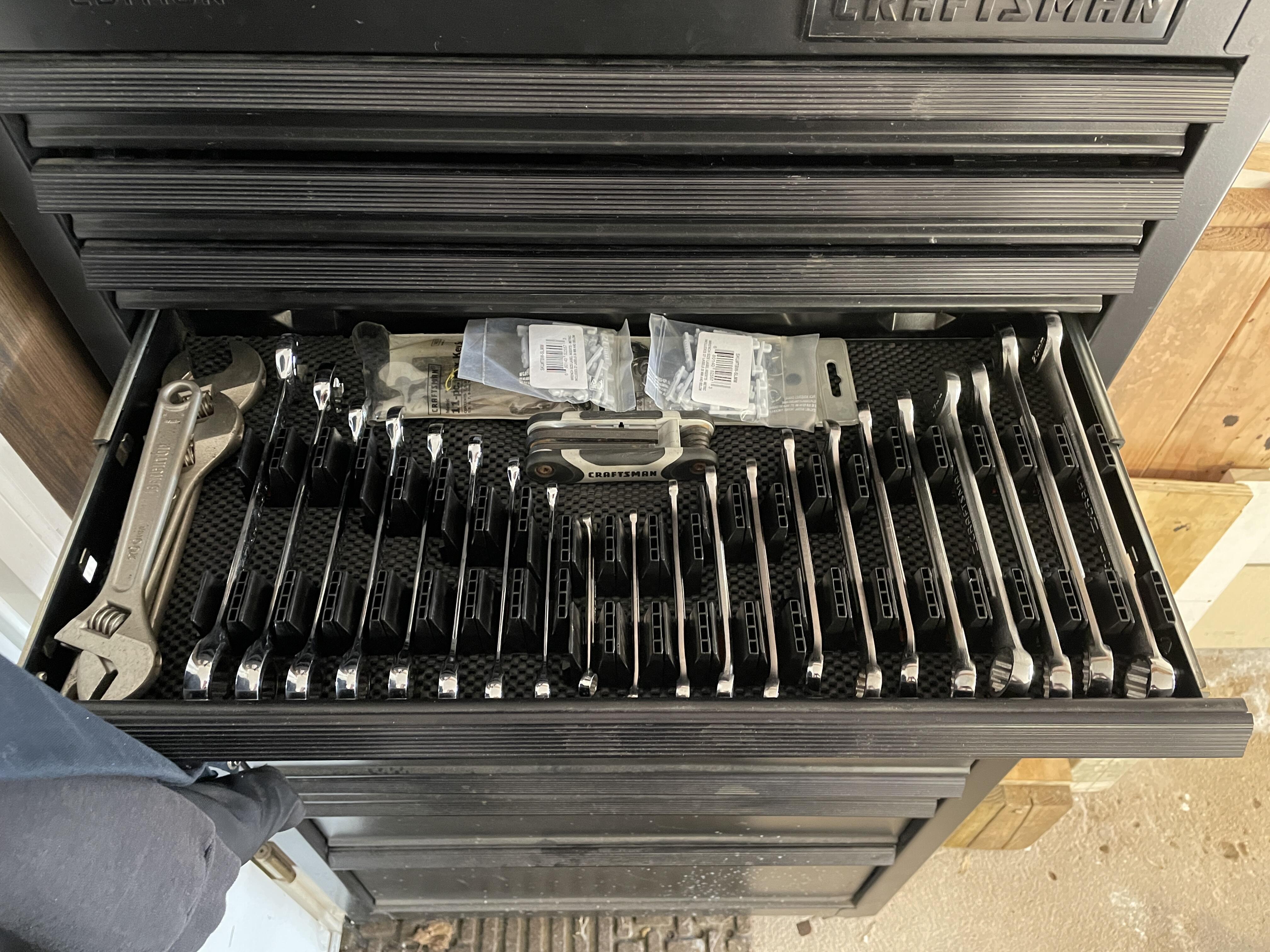
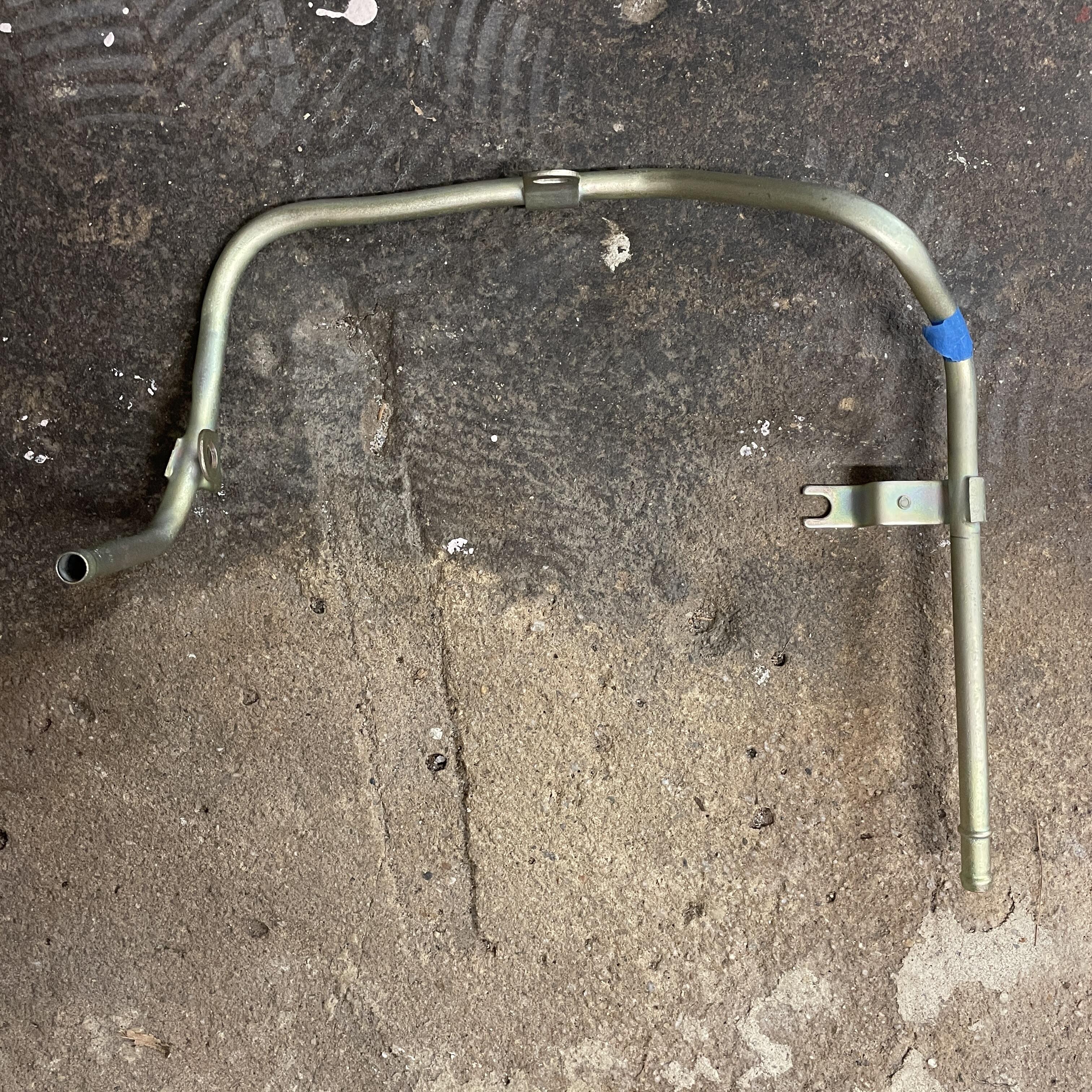
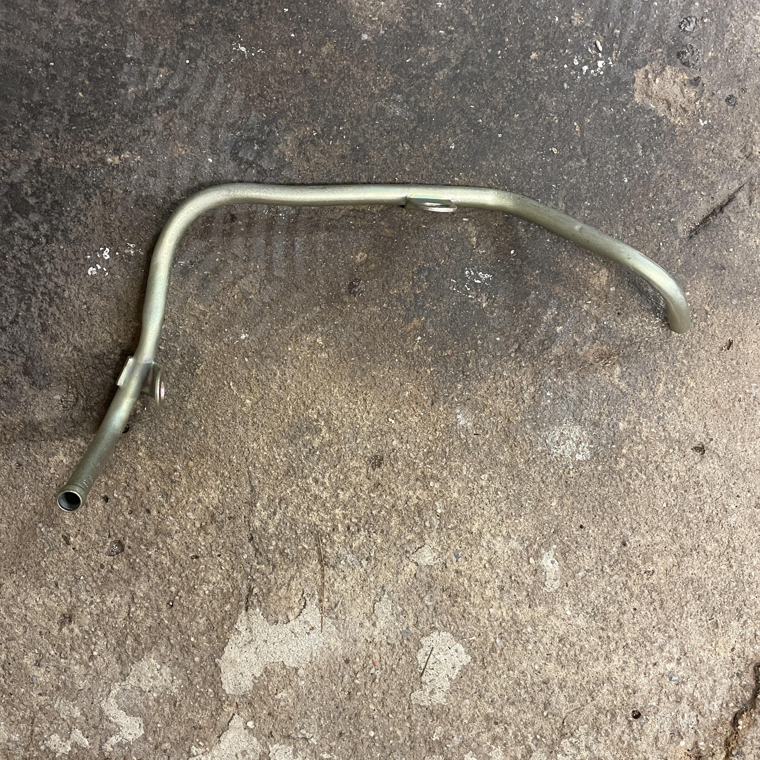
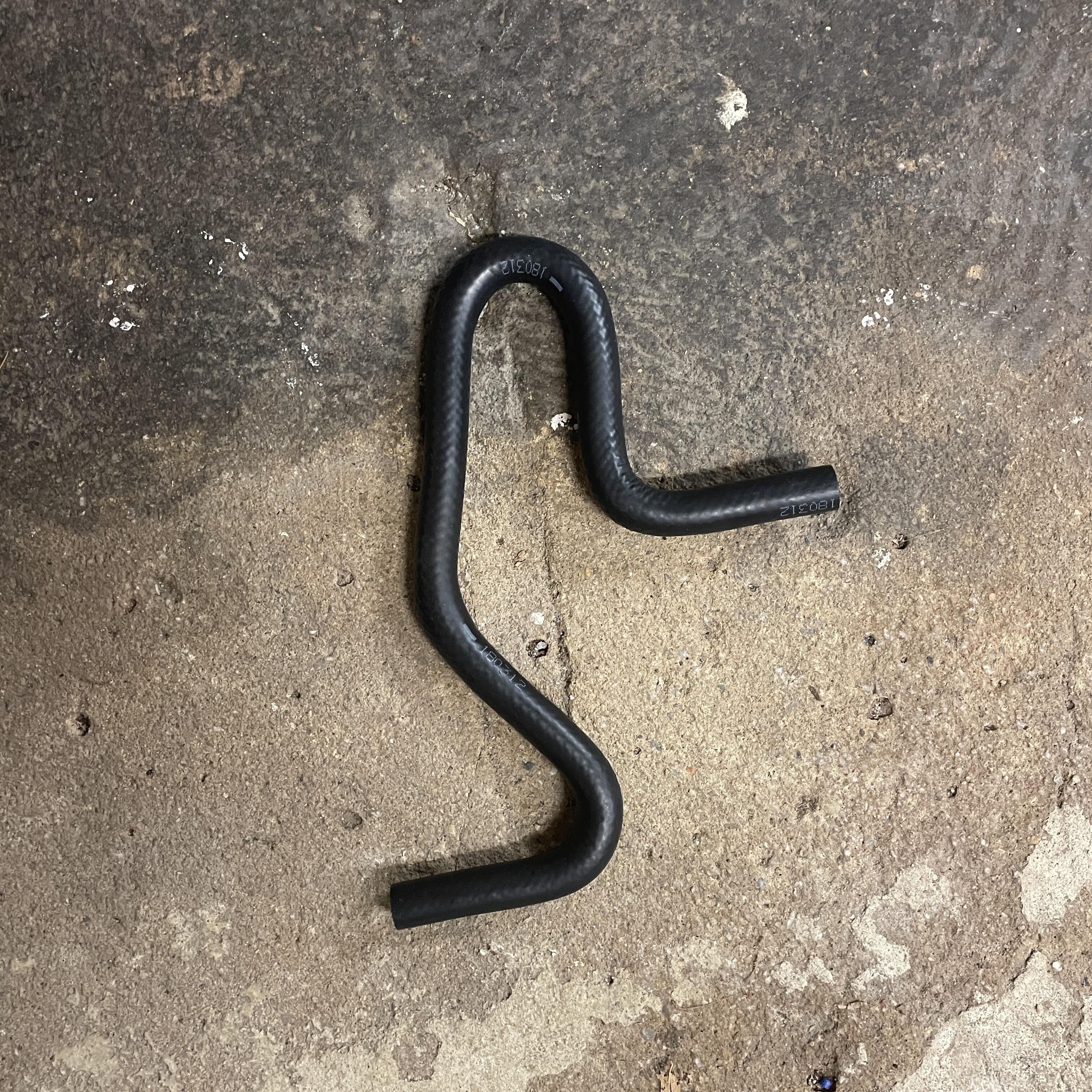
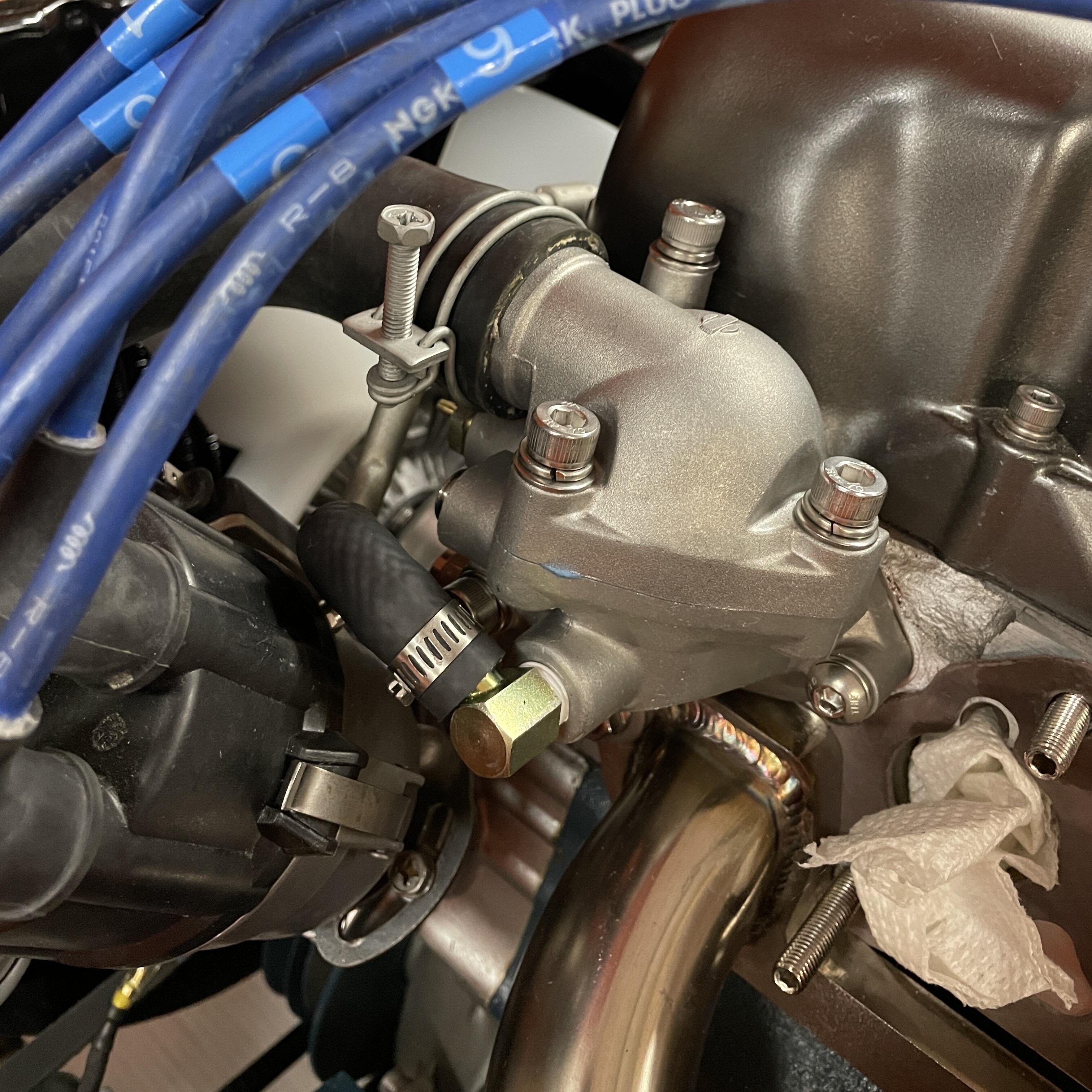
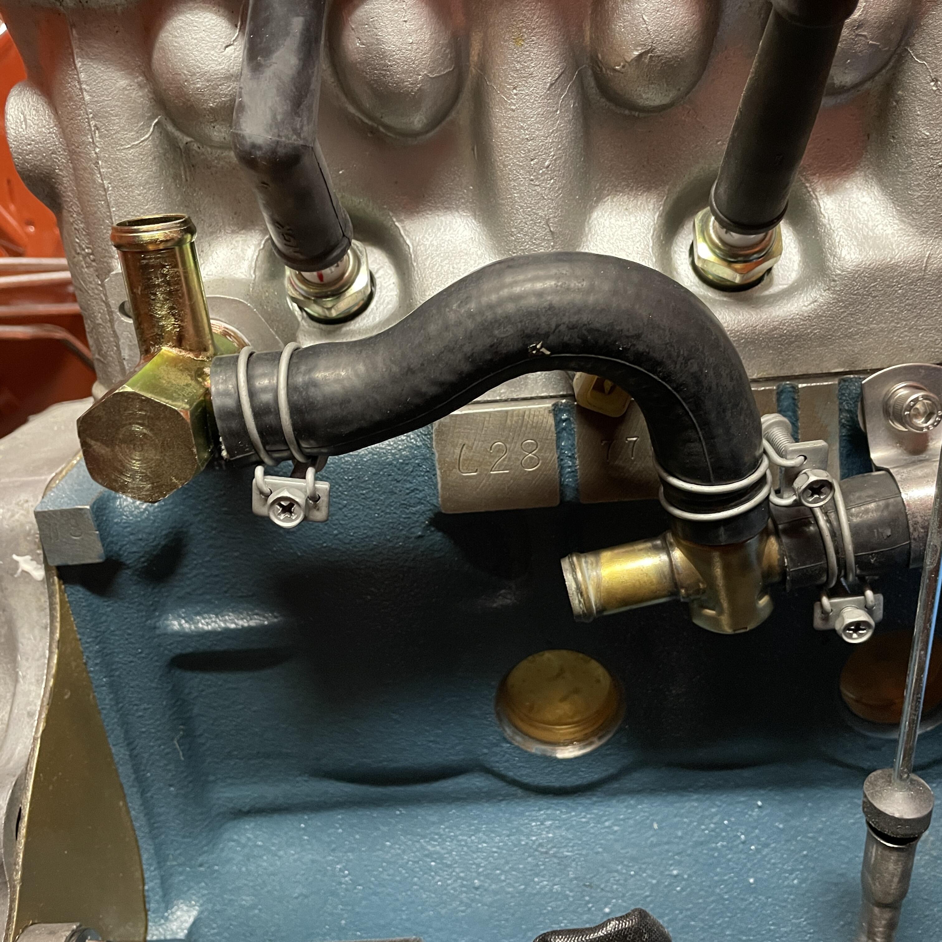
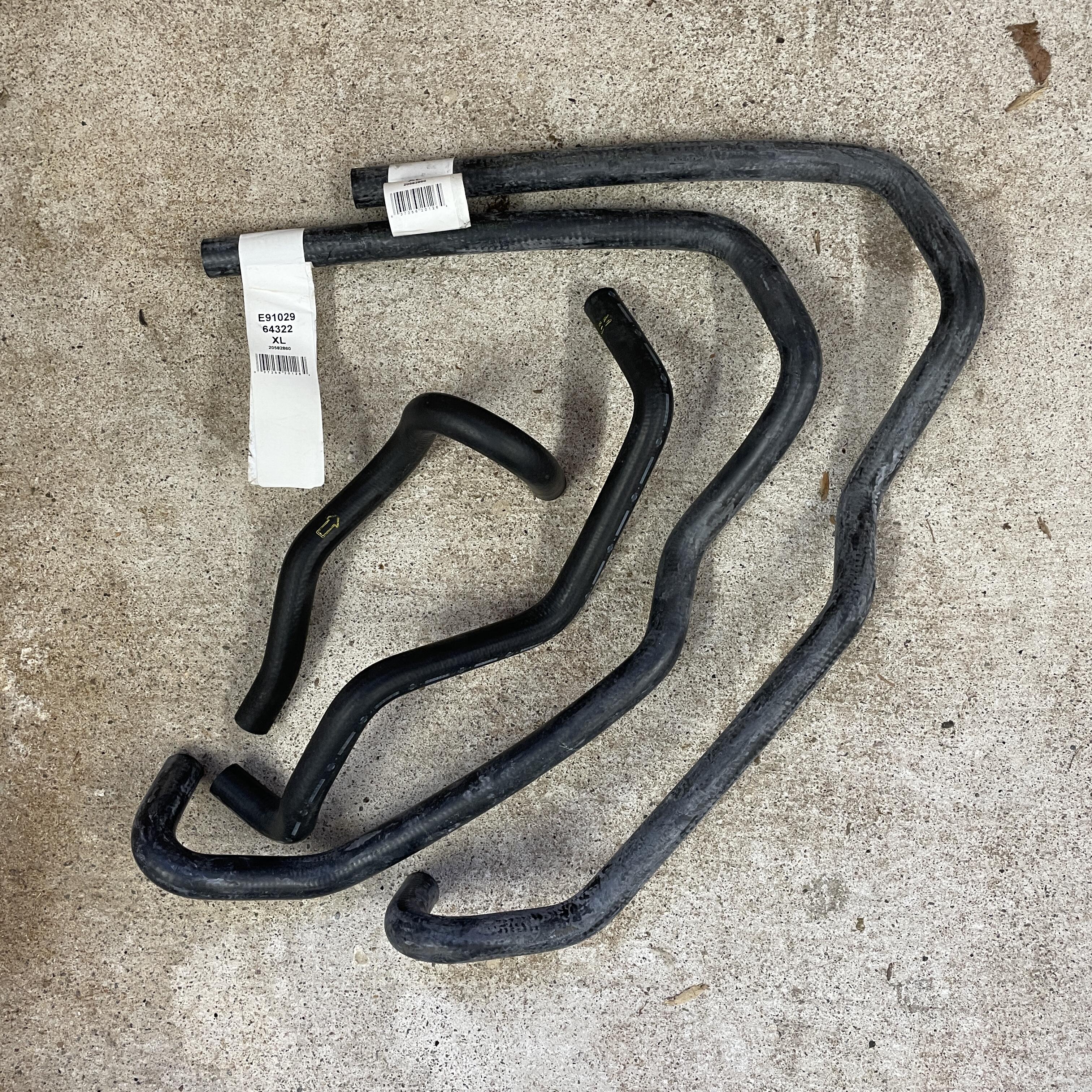
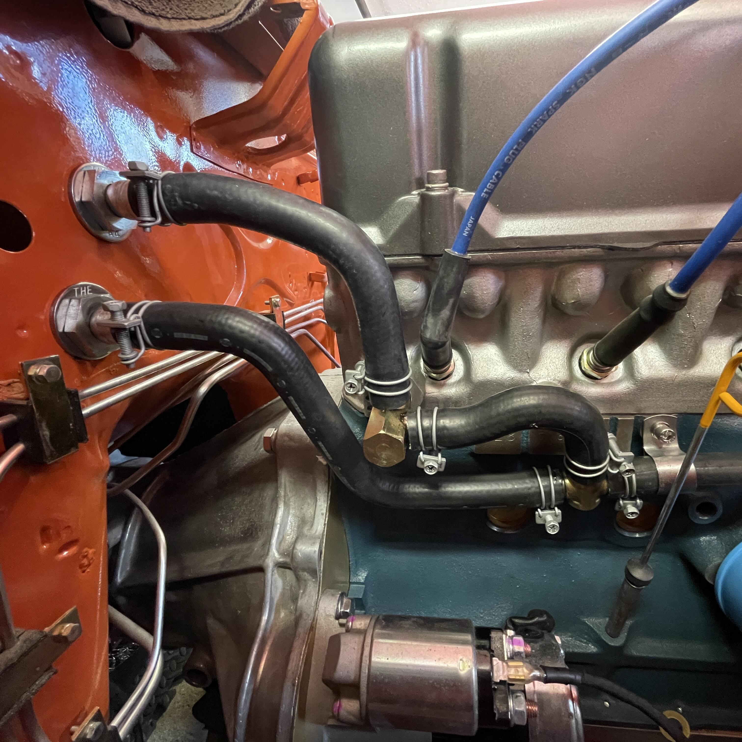
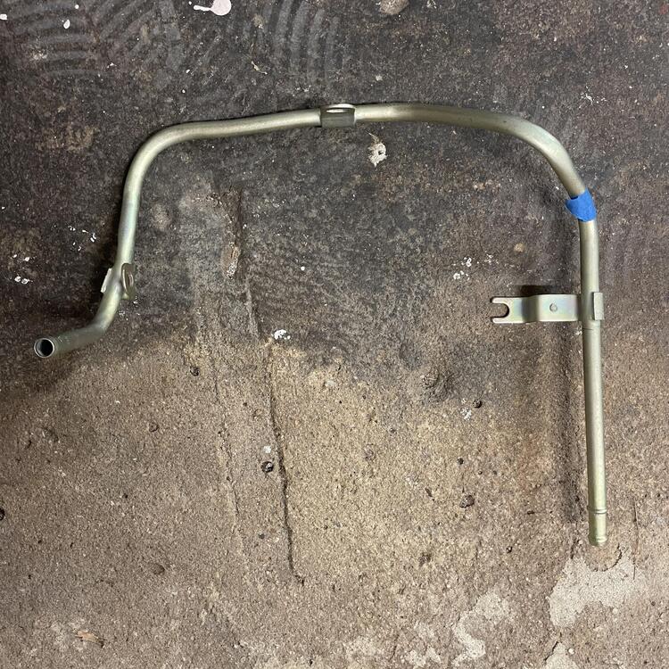
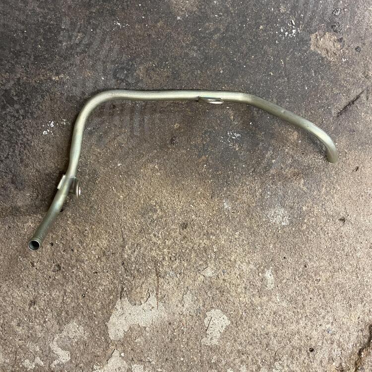
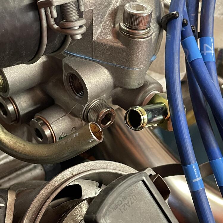
I took a break from the car to do some self care and get my mind in order by getting my tools in order. I bought myself a few packs of Toolbox Widget organizers, and so far they are doing the job. The box doesn’t hold quite as much now, but I also don’t have wrenches and sockets sliding around all over the place and piled up on top of each other. Putting a layer of anti-slip foam on the bottom first really helps it feel slick. Not sure how I’m going to keep the dust out, though. … So you may remember that I was having a hard time adapting the 240z coolant routing to having Mikuni triples because that eliminates the carburetor warming channel that connects the bypass tube to the thermostat housing. I had experimented with just running a stainless steel tube in place of that system, but it fouled the manifold and front carburetor. After much back and forth with various thermostat housings I found that the early ZX housing is the one I wanted. It has many extra ports, but these can be plugged with various fittings. The hardest one to find is the 1/4” BSPT, but McMastercarr had them. Next I tried a few different Nissan fittings that are 1/4” BSPT male to a 3/8” hose barb. I found the 105° angled one to work best for clearing the distributor. Then I found a 280zx bypass tube, which more or less mounts right up, but because it is meant for the fuel injection system I had to remove approx. 9” from the side that wraps around the thermostat and put a new bead at the point where I cut it. It also needed some spacers to change the geometry and allow it to clear the temperature sensor and point the tube at the 3/8” fitting mentioned above. After that I needed a ZX water inlet with the 3/8” tube coming off the threaded adapter that connects to everything already discussed. That has a 5/8” tube pointing back to the heater hoses, so I had to replace all of my 3/4” hose. It also meant going full ZX with all of the fittings and getting rid of the 240z y-pipe. I had to find a coolant regulator/check valve, which is nearly a unicorn part. I know seller with some that are NOS in the box, and normally I wouldn’t go with used parts on a fresh engine build, but I’m not paying $175 plus shipping for something I can get for $30 in good used condition and is essentially just a 3/8” tee with a check valve. The coolant system is now closed. After much trial and error and purchasing too much hose, I have the whole system plumbed and clamped. I only used one of the OEM 240z hoses, and I cut it down significantly. They wouldn’t have worked at all with the Vintage Air system I have, so I put a pair of their bulkhead barb to threaded fittings coupled to their 90° barb fittings. I bought a pair of Continental hoses with a bunch of turns from Summit Racing, which allowed me to keep everything under the dash pretty snug. I was worried I would need to make a bracket for the heater control valve, but it’s floating pretty far from everything so it should touch anything even with a huge amount of vibration. So now I just need to check all my fasteners and get a radiator overflow tank. Next is decide whether to move on to the fuel system or put the AC lines in.


-
1973 240z Custom Wiring From Scratch
Matthew Abate replied to Matthew Abate's topic in Build Threads
Pretty cool! I’m surprised how well that fits so far.