Matthew Abate
-
Posts
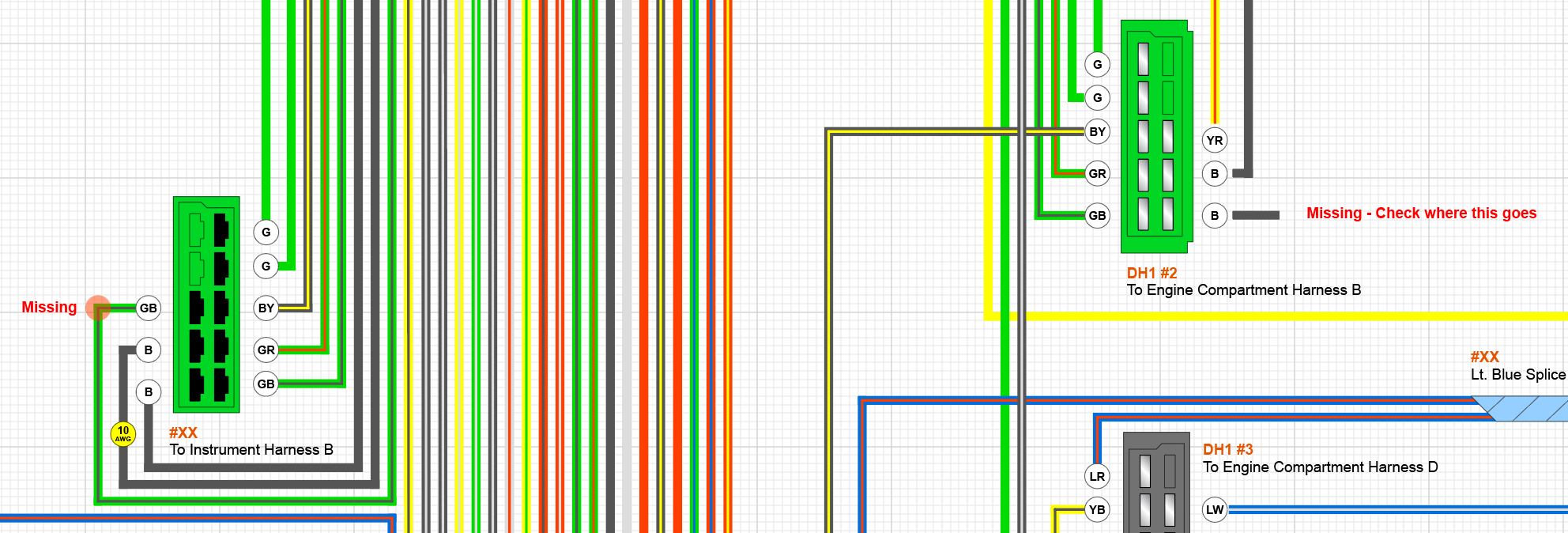
1,187 -
Joined
-
Last visited
-
Days Won
16
Content Type
Profiles
Knowledge Base
Zcar Wiki
Forums
Gallery
Events
Downloads
Store
Blogs
Collections
Classifieds
Everything posted by Matthew Abate
-

1973 240z Custom Wiring From Scratch
Matthew Abate replied to Matthew Abate's topic in Build Threads
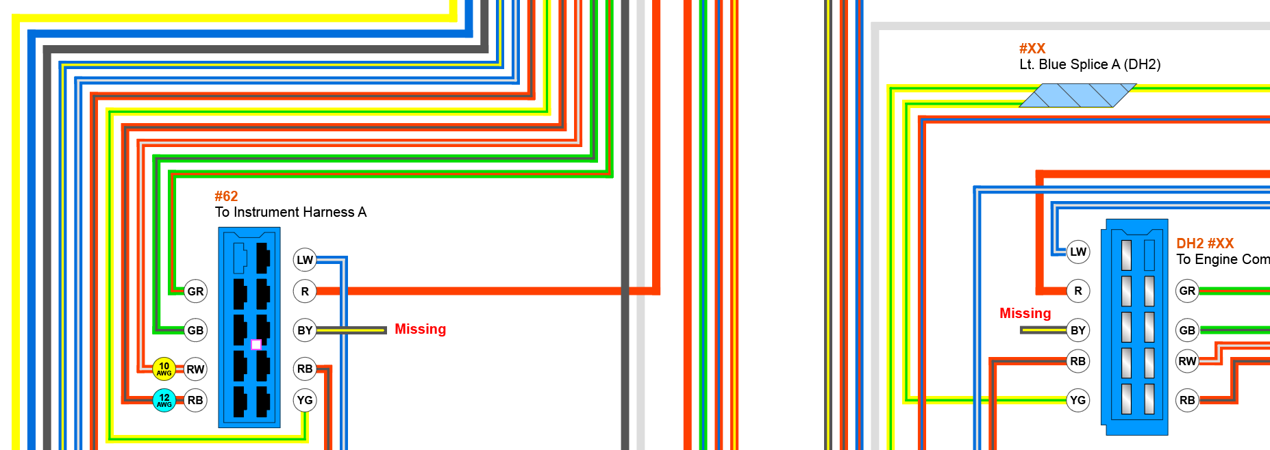
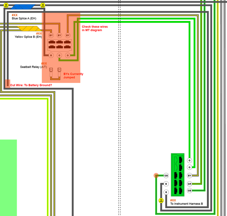
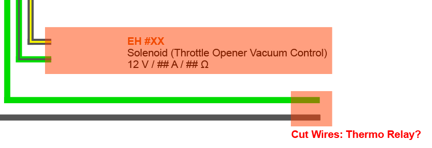
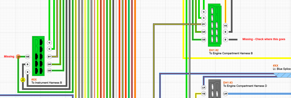
I've made major progress on my wiring diagram. I didn't finish the fuel harness for the rear of the car because I don't have one handy, but I don't think it is that important for moving forward. I do have a handful of mysteries, though. I think they are mostly caused by my having an engine harness for an automatic, but I am not sure. I will try comparing the two wiring diagrams in the morning. In the mean time, maybe someone knows the answers… 1. On the two blue 10-pin connectors that join the dashboard harness to the engine harness, I have a Black wire with a Yellow stripe missing from both sides. It's in the FSM on pages BE-2 and BE-3 but the only thing I am seeing in the actual diagram (page BE-5) is the Black wire with a Yellow stripe that goes to the water tank. In my harness that wire is actually Black with a White stripe, and most of the Black wires with a Yellow stripe are related to the seatbelt relay, the throttle opener, and the thermo relay. 2. On my engine harness I have a Black wire that has been cut, which I have labeled "battery ground?" in the drawing below, but that probably isn't right. It comes out of the main trunk of the harness near the seatbelt relay for the automatic car and runs back to the green 10-pin connector that joins the dashboard harness to the engine harness. That wire is completely missing on the dashboard side. 3. I have three cut wires and a missing wire that I am pretty sure are related to the thermo switch and the throttle opener, but I want to be entirely sure. I am pretty certain that the Black wire with a Yellow stripe, which has been cut, goes to the throttle opener. The Green and Black wires, also cut, branch from the main trunk of the harness at the same point as the Black wire with a Yellow stripe, near the distributor in the front left corner of the engine bay. On the other end, the Green wire connects to the Voltage Regulator, the Distributor Condenser, and ultimately the fuel pump in the back of the car. The Black wire connects to all of the other black wires in the Engine Harness going to the lights, Alternator, Starter, and the Intermittent Relay. In retrospect, I think these two wires go to the Thermo Switch and control the EGR vacuum control. The missing one is the Green wire with a Black stripe, which could be one of the other three and is just mislabeled in the FSM, or could be entirely missing. I'm pretty sure it's missing because there should be a GB wire going to the green 10-pin connector that connects to the dashboard harness in the pin highlighted with the red circle below. This GB wire would connect to the Yellow wire with a Red stripe on the dashboard harness, which we have previously discussed as being for the throttle opener. In the FSM this is shown going to the Relay Assembly Type K24 (Throttle Opener Relay), but on the manual cars. 4. I have three items in the FSM wiring diagram that I am missing in my own because I don't have any connectors remaining to identify. Here's what's in the FSM: Solenoid Valve Assembly (EGR Vacuum Control) - Different from the Throttle Opener Vacuum Control Thermo Switch Assembly (Temp Sending Switch) - This is probably two of the cut wires above Relay Assembly Type K5 (Distributor Relay) - Possibly unimportant since I am switching to an e12-80 Inhibitor Switch - Possibly what I have labeled as the Seatbelt Relay, which is what the FSM has that connector labeled on page BE-2
-
Cool. Thanks for the tip.
-
Question for the room: is it better to put the windshield in before or after other things? I feel like I could put my windshield in now, but I have this hazy feeling that some thing’s might be easier to instal with it out. Conversely, I feel like installing the windshield with other things in the car (dashboard) might make it harder.
-
1973 240z Custom Wiring From Scratch
Matthew Abate replied to Matthew Abate's topic in Build Threads
Ooooh, duh. Okay, yeah. Not sure why I didn’t realize that. I‘ve gone around a couple of times on the topic of the tach mod. Some people insist that the tach needs to be upgraded and some people insist that it doesn’t. Either way I will work this out later in the process and proceed with the engine harness. -
1973 240z Custom Wiring From Scratch
Matthew Abate replied to Matthew Abate's topic in Build Threads
Now that I am almost done verifying (and fixing) my documentation of the two dashboard harnesses I just have one last thing to do one the dash: figure out where the resistor for the Tach is supposed to be. I just traced everything from the Tach and Ignition Switch plugs on the dashboard harness all the way to the ballast resistor on the engine harness and I am not seeing one. I took a look at this thread and the photos that @zKars posted on page 2 look like it is located on the engine harness just inside the cabin, close to the colored connectors, but that's one of the 2,200Ω resistors on a 280Z: Unfortunately, I don't have anything even approximating this on mine. I thought maybe my dash is from a different year, but the FSM for the '72 shows a 0.5Ω resistor between the ignition and the tach. The '73 FSM shows a resistor wired up the same way, but does not indicate how many ohms of resistance if provides. I found a resistor on the 1974 FSM diagram and it is on the engine harness on a Blue wire, similar to the photo above, that runs to a splice to the Full-Transistor Ignitor Unit, and the Ignition Coil, but I am not sure this serves the same purpose. I'd like to figure out how it is supposed to be set up on the 1973 harnesses, but I also need to figure out what I should do for my final setup because I have a 280ZX distributor with a E12-80 Ignition box and I would like to make my regular 1973 tach work with it rather than doing a bunch of unnecessary modifications there, per @Zed Head's recommendation. -
1973 240z Custom Wiring From Scratch
Matthew Abate replied to Matthew Abate's topic in Build Threads
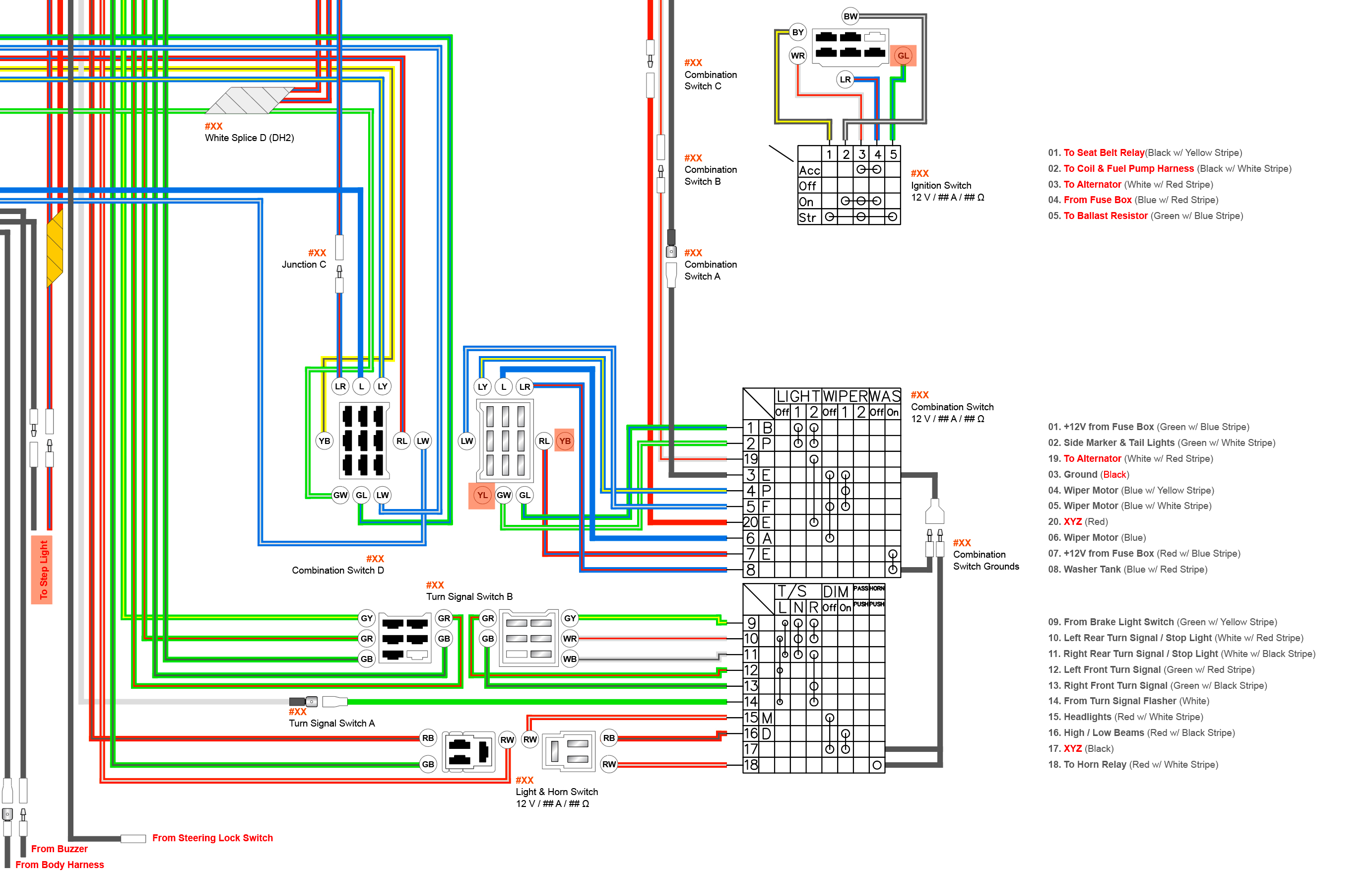
I updated the diagram for the Combination (Wiper) and Turn Signal Switches to match the samples I have on hand and the 1973 FMS: The Red text needs better labeling. I went with what is in the FSM where I could for now. Also, in my sample, #2 (Blue with a White stripe) is actually Yellow with a Blue Stripe. It changes to LW at the connector and goes to the Intermittent Relay.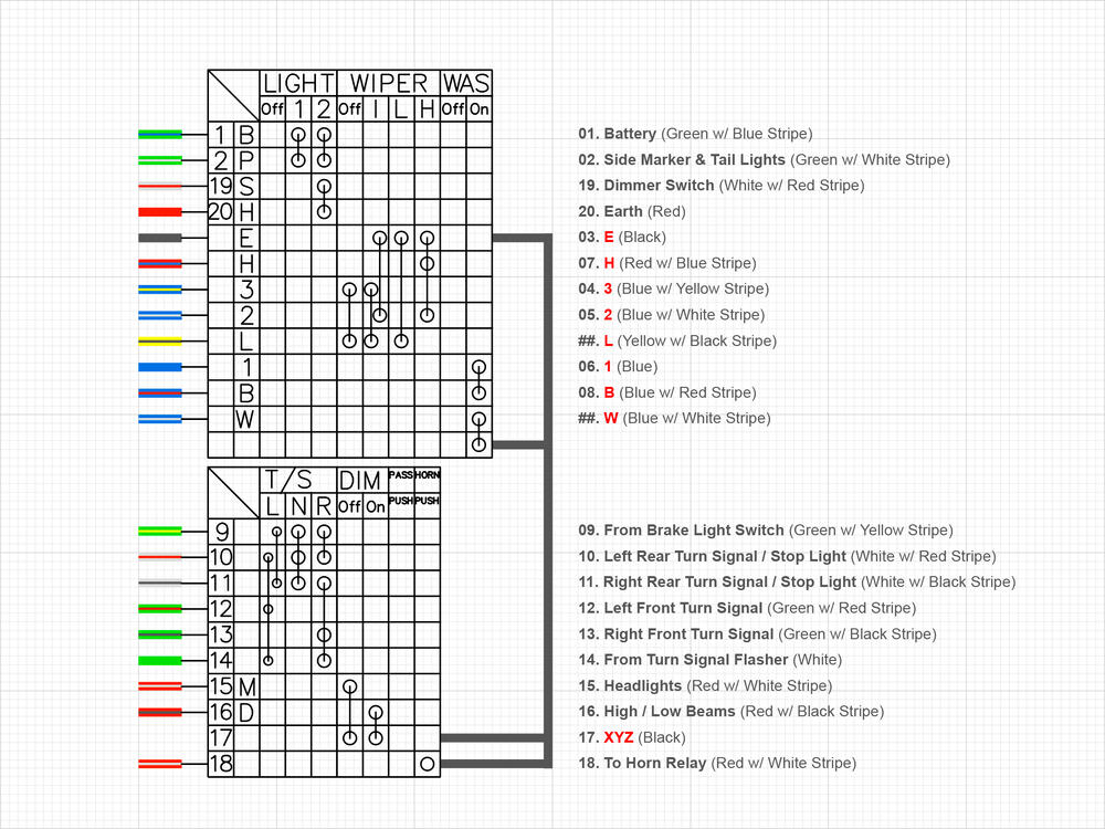
-
1973 240z Custom Wiring From Scratch
Matthew Abate replied to Matthew Abate's topic in Build Threads
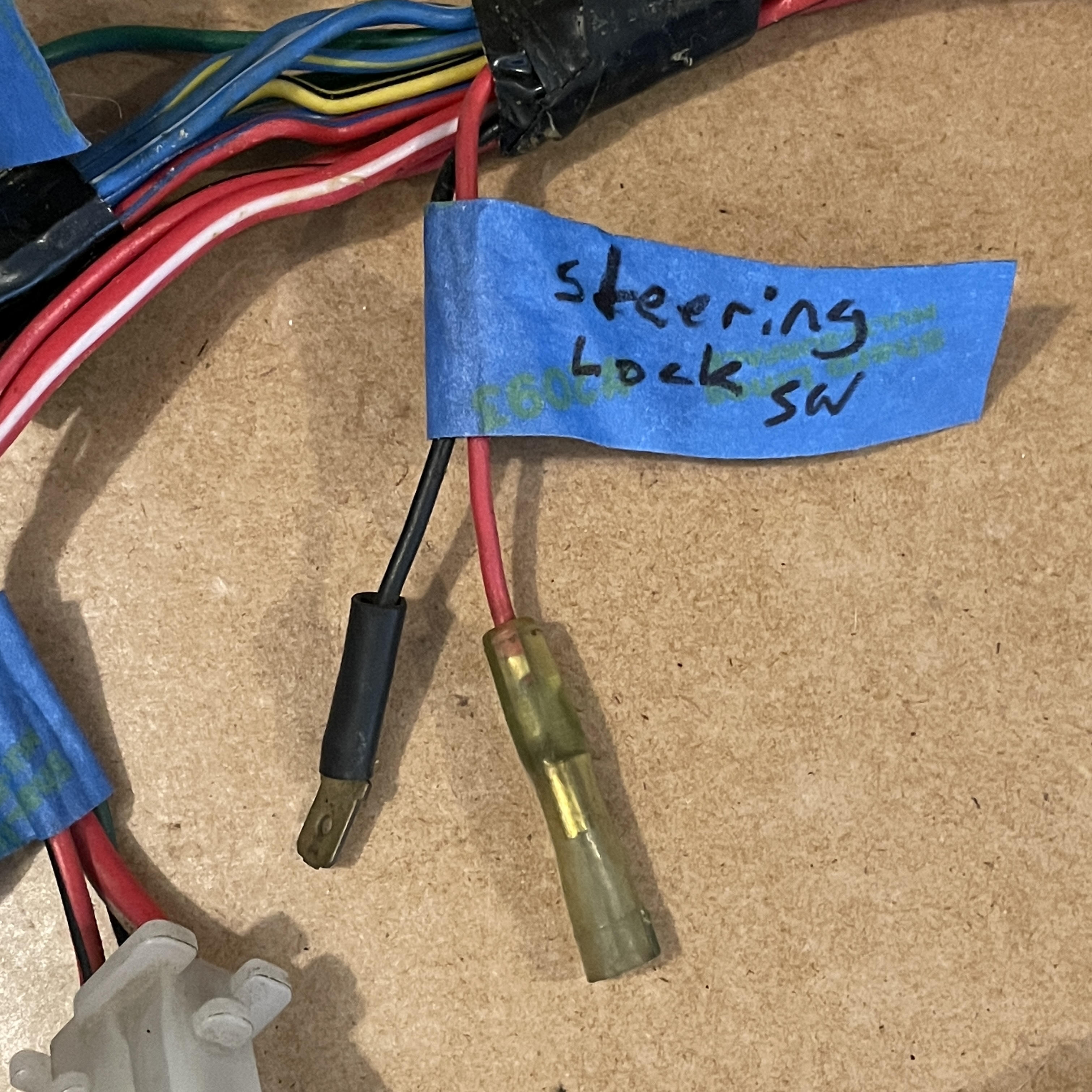
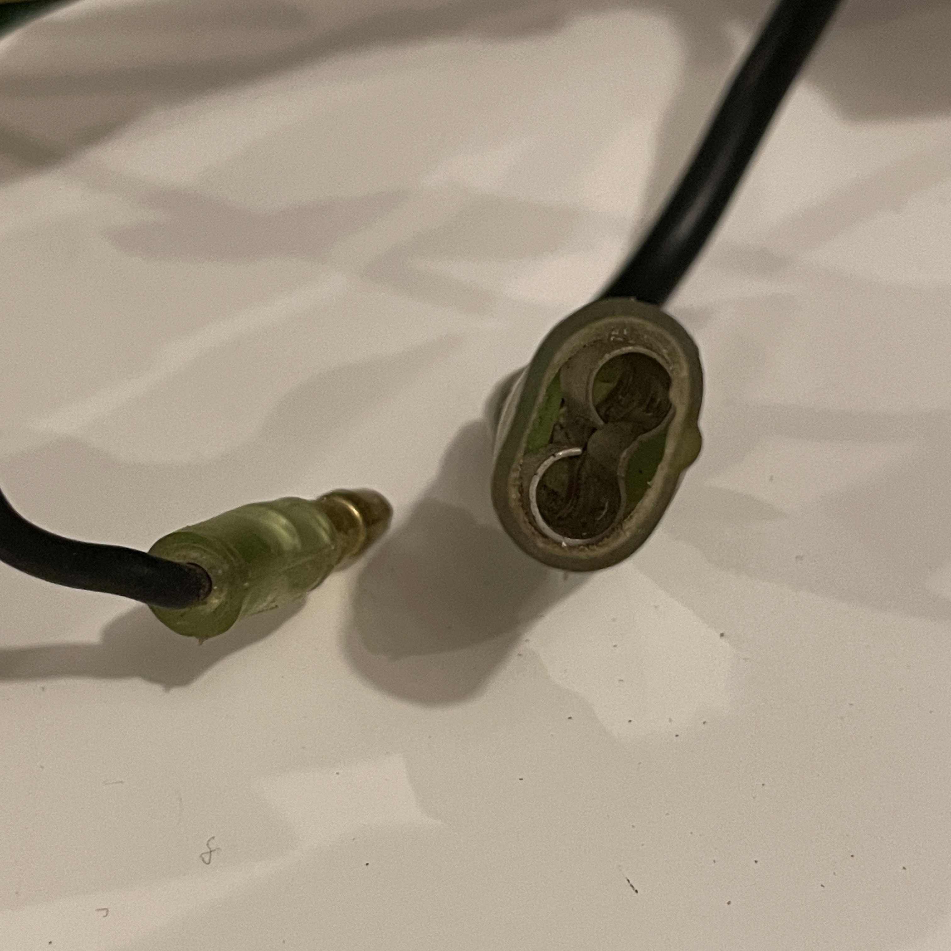
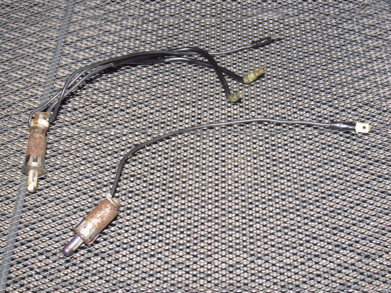
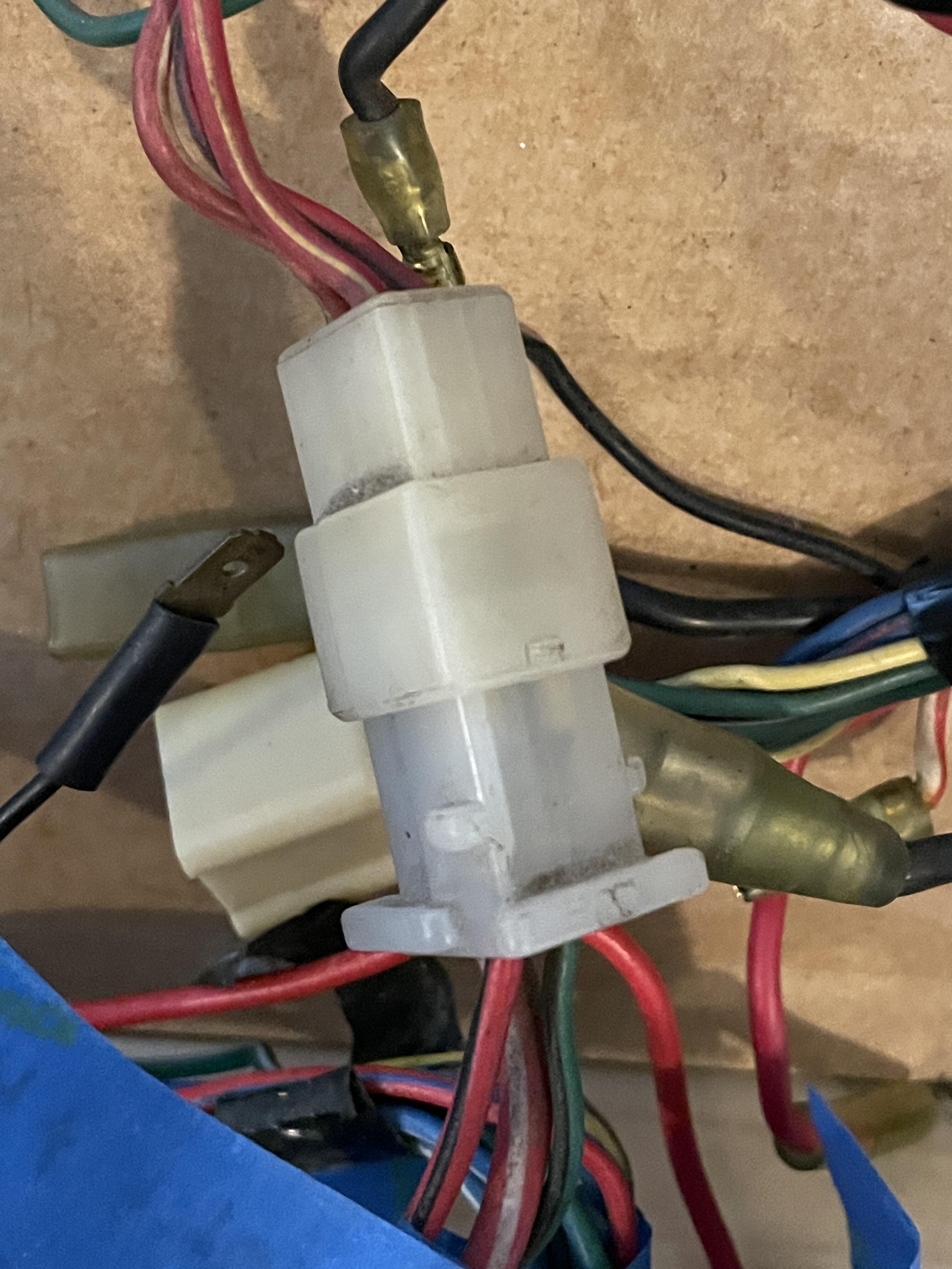
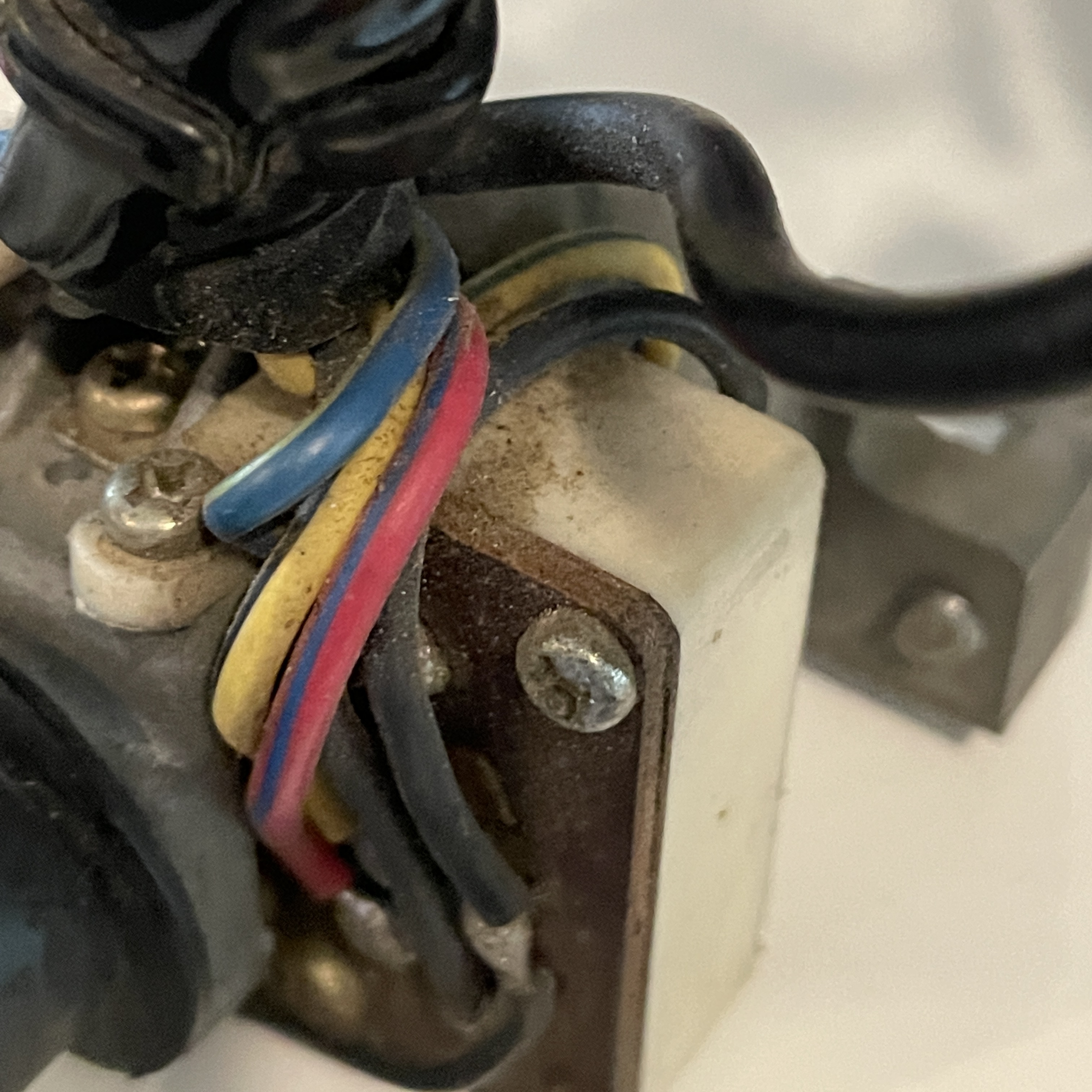
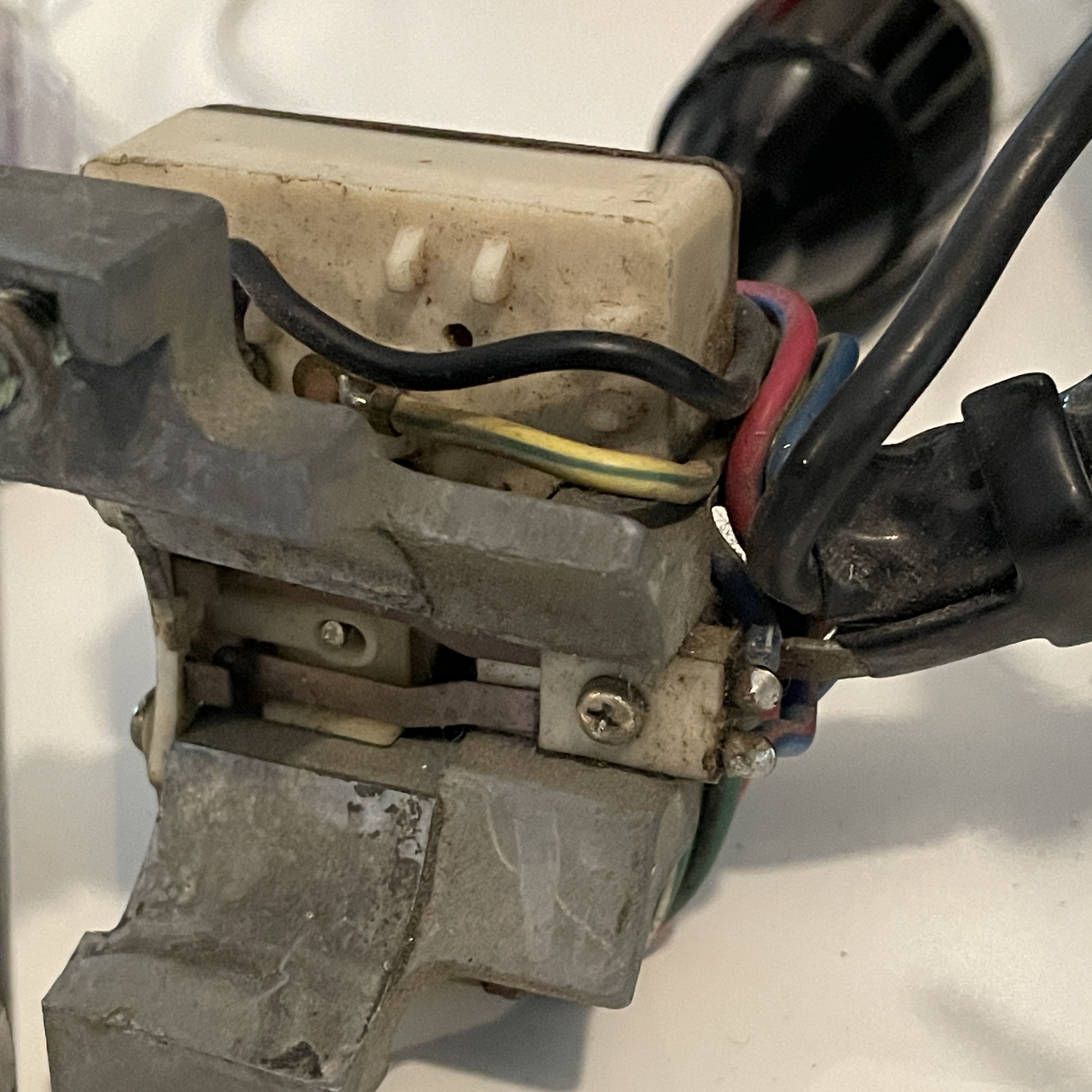
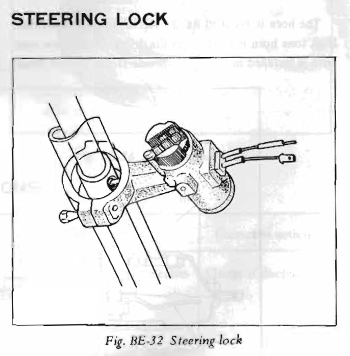
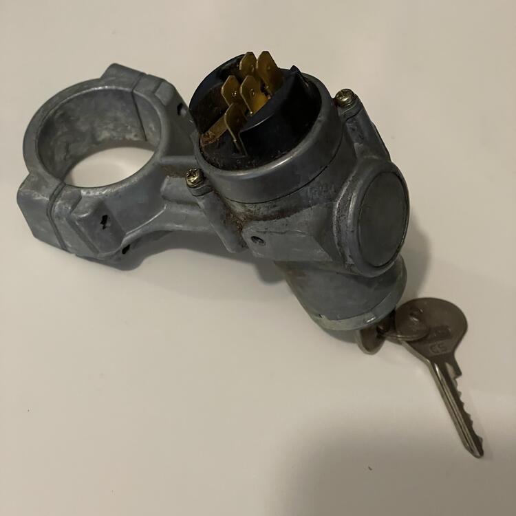
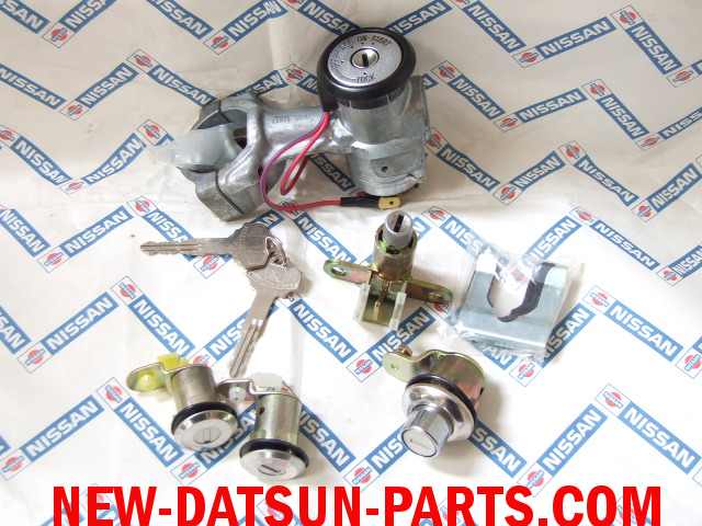
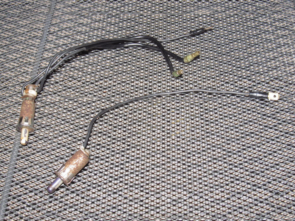
This post is just for documentation purposes and to put a bow on some things I have brought up over the last few days… I retraced the Red wire with a Blue stripe coming out of my wires switch and confirmed that it 100% does not go to the fuse box. It goes to the center pin on the 9-pin connector on Dashboard Harness 2 (the one with all of the lightbulbs on it). That center pin on the 9-pin connector on the harness goes to the black connector that connects to the Engine harness. Note: in the FSM this connector is white. The white one on my harness is black in the FSM. I verified this by the wires they contain and by the shapes of the connectors, which are unique. That pin on the black connector switches to a Blue wire with a Yellow stripe on the engine harness and goes to the 6-pin connector for the wiper motor. Also, there is no second buzzer in the wiring diagram in the 1973 FSM. Just the single 3-wire buzzer with the 3-pin connector, which I have accounted for. In the FSM, the "STG Lock SW" I keep bringing up has a Red wire that is spliced to a Re wire with a Blue stripe running to the left step light as well as some of the dashboard lights (map light, glove box light, room light) and ends at a 6-pin connector for the fuse block. That pin has a second Green wire with a Blue stripe that runs directly to position #2 on the wiper switch (after a color change to Green with White). The connector on the Fuse Block also swaps colors to Green with White ( ¯\_(ツ)_/¯ ). I already mentioned that the Black wire on the "STG Lock SW" runs directly to the left door switch. On page BE-23 of the FSM, it states, "The steering lock is combined with the ignition switch to a single unit which contains warning buzzer micro-switch for reminding the [driver] to lock the steering. The microswitch is connected to a warning buzzer." This corresponds to what @SteveJ has said. On the next page it mentions the ALR, which is not in any of the diagrams… The two wires I have in the harness go to this integrated steering lock. The reason I can't find it in my stuff is that I don't have one. I have one from an older car. Here's what the one for a 1973 240Z should look like (note the two wires coming off of it with spade connectors): And here is what I have (note the lack of the two wires): Here's a picture of a different version I found on new-datsun-parts.com, probably from an older year (note the plastic ring with the two wires, i.e. non-integrated steering lock): So, questions answered. I just need to find a 1973 ignition switch or the non-integrated one mine is missing for the problem to be solved. In other news, the Comb. Switch in the FSM for 1973 is pretty different from 1973 wiring diagram I downloaded from this site. First, the positions are only numbered for the first four wires (1, 2, 19, & 20). In the FSM, the wires from top to bottom are: GL (Labeled as Position 1) GW (Labeled as Position 2) WR (Labeled as Position 19) R (Labeled as Position 20) B RL LY LW YB L LR LW B (back side) B (back side) There are 14 lines running to the box denoting the Combination switch, with 12 color labels. There are 13 rows showing the jumpers in the switch and how the mechanisms route electricity to the wires. The 13th row is dedicated to one of the 2 black wires coming out the other side of the box to connect it to the TS switch, as discussed, and does not go to the GB wire going to the horn. When looking at my actual switches, there are 14 pins across 6 connectors on the wiper switch, two of which connect to each other. They are: 9-Pin Connector GL (Goes to Body Harness, Fog Light Switch, Radio, Rheostat, & Cigar & Hazard Fiber Optic Light Source) GW (Changes to GL and goes to Fuse Box, as mentioned above) RL (Goes to the Engine Harness where it changes to LY and goes to the Wiper Motor) LY (Goes to Engine Harness and terminates at the Intermittent Relay) LW (Goes to Intermittent Relay and splices to wires going to the Engine harness and ending at the water tank) L (Goes to Intermittent Relay) LR (Goes to Engine Harness and branches to the Wiper Motor and Reverse Light Switch on Transmission, but I need to verify this) YB (Goes to the Engine Harness where it changes to B and goes to the Wiper Motor) YL (Changes to LW at the connector and goes to the Intermittent Relay and the Engine Harness where it goes to the Wiper Motor) Spade Connector G (Splices to many other black wires that run to various dashboard & center console instruments, the Rear Window Defroster Relay, and the Engine harness, terminating at the Alternator) Bullet Connector #1 WR (Splices to WR or L wires going to Alternator, Defrost Relay, Fuse Box, Accessory Relay, Ignition Switch, Ammeter, etc.) Bullet Connector #2 R (Goes to the Fuse Block, then to the Engine Harness and ending at the Fog Lights) Bullet Connector #3 B (Connects to Double Bullet Connector) Double Bullet Connector B (Connects to Bullet Connector #3 and to a B wire on the TS Switch)
-
1973 240z Custom Wiring From Scratch
Matthew Abate replied to Matthew Abate's topic in Build Threads
I just noticed some other goofiness related to this: In the wiring diagram I downloaded from this site, the yellow wire coming off the buzzer connects to the R/L wire coming from #7 on the wiper switch which splices to a R/L wire for the step light and continues on to the fuse box. Great, except in my harness the R/L wire coming from the wiper switch connects to directly to the engine harness (no splices) and then turns into w L/Y wire for the wiper motor. I think this is related to the missing YL & YB wires I see on my wiper switch that I mentioned earlier. Gotta do some more sleuthing. -
1973 240z Custom Wiring From Scratch
Matthew Abate replied to Matthew Abate's topic in Build Threads
I guess what I am worried about is whether or not I need to complete this circuit in order for other things to work, and it is sounding like that isn't an issue. -
1973 240z Custom Wiring From Scratch
Matthew Abate replied to Matthew Abate's topic in Build Threads
Do you mean this guy? - https://maseraticompound.com/products/datsun-240z-series-1-anti-theft-buzzer -
1973 240z Custom Wiring From Scratch
Matthew Abate replied to Matthew Abate's topic in Build Threads
Normally, this would make sense to me and is what I would have assumed before looking at the documentation from Nissan, but the wiring diagram in the FMS shows a Steering Lock Switch completely separate from the Ignition Switch: The R wire goes to a splice connecting to the left side step light harness and the B wire is the third wire going to the left door switch illustrated in the post above. I have both of these wires in the harness on my table, but no switch that could be the STG LOCK SW in the FSM. By the way, these R & B wires have no relationship to the Ignition Switch, so I am wondering if STG stands for something other than "Steering."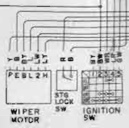

-
1973 240z Custom Wiring From Scratch
Matthew Abate replied to Matthew Abate's topic in Build Threads
Right. And the third one goes to the steering lock switch. Incidentally, I can't find a steering lock switch in all of my parts, and I can't find a photo of it online. I assumed (based on the diagram) that it is a separate switch from the ignition, because one of the 5 wires that comes from the back of the ignition goes to it. I also don't have either of the two buzzers nor the 2,200 Ω Resistor in any of my piles of stuff. -
1973 240z Custom Wiring From Scratch
Matthew Abate replied to Matthew Abate's topic in Build Threads
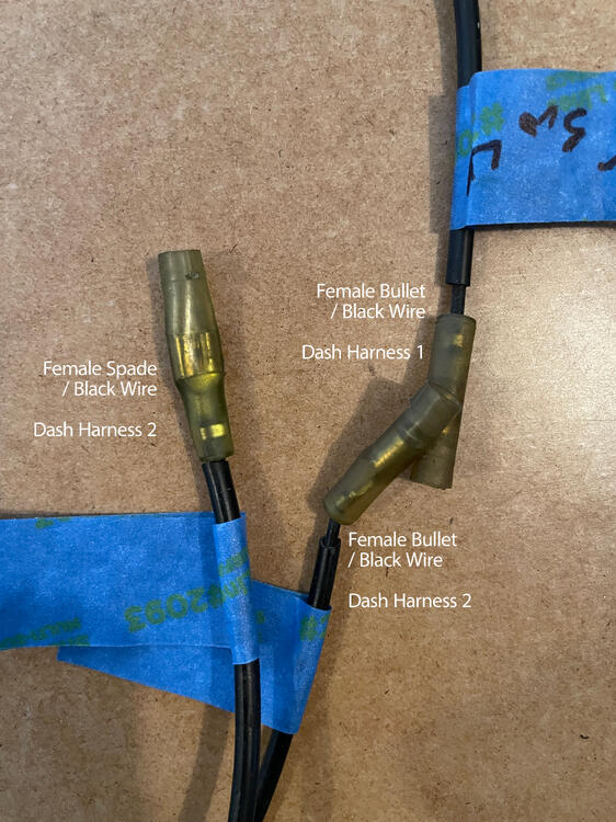
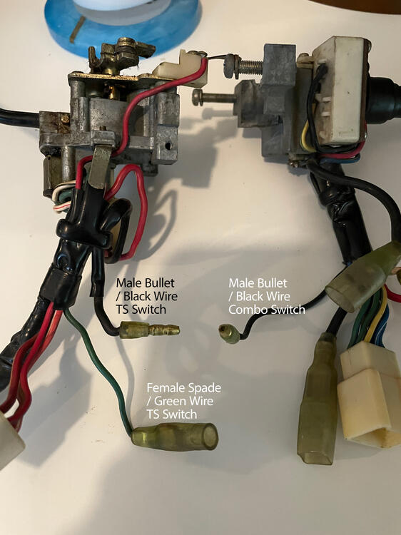
SOLVED! The second black wire with a female spade connector is not, in fact a spade connector, but a double female bullet connector. I think this is the connection @SteveJ mentioned a couple of posts ago. I figured this out after looking at this 240Z Headlight-Wiper Switch Identification post and noticing there was a wire looping back on itself. It's always something simple. Here are some detail shots: Here's an updated diagram: I also sort of answered my own question about the door switches. In the 1973 240z the driver's side door switch has three black wires coming off of it; one with a spade connector and two with bullet connectors. I don't know if other years are like this, but I have only found this three-wire switch once and it is very used. I may need to splice the missing wire onto one of the ubiquitous two-wire switches to make it work unless someone knows of an alternative part.


-
1973 240z Custom Wiring From Scratch
Matthew Abate replied to Matthew Abate's topic in Build Threads
Here's an updated diagram taking into account @SteveJ's comments: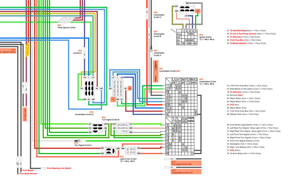
-
1973 240z Custom Wiring From Scratch
Matthew Abate replied to Matthew Abate's topic in Build Threads
I think it's okay. The wires in my harness might be the wrong colors but they are going to the right places. Something else that is confusing me is the door switches. I looked at the replacements available at various stores and I am seeing three different configurations: one female spade connector one male bullet connector two female spade connectors -
1973 240z Custom Wiring From Scratch
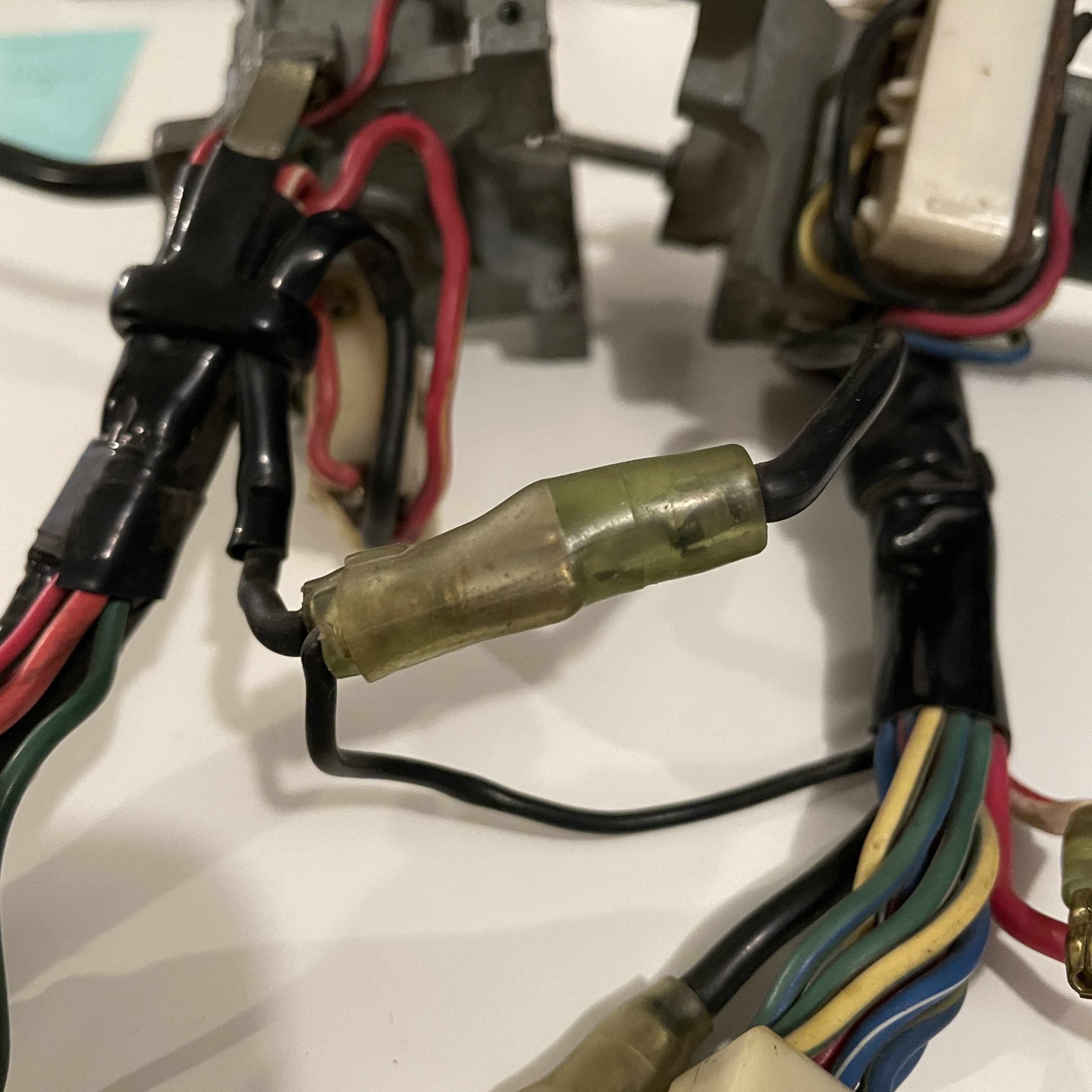
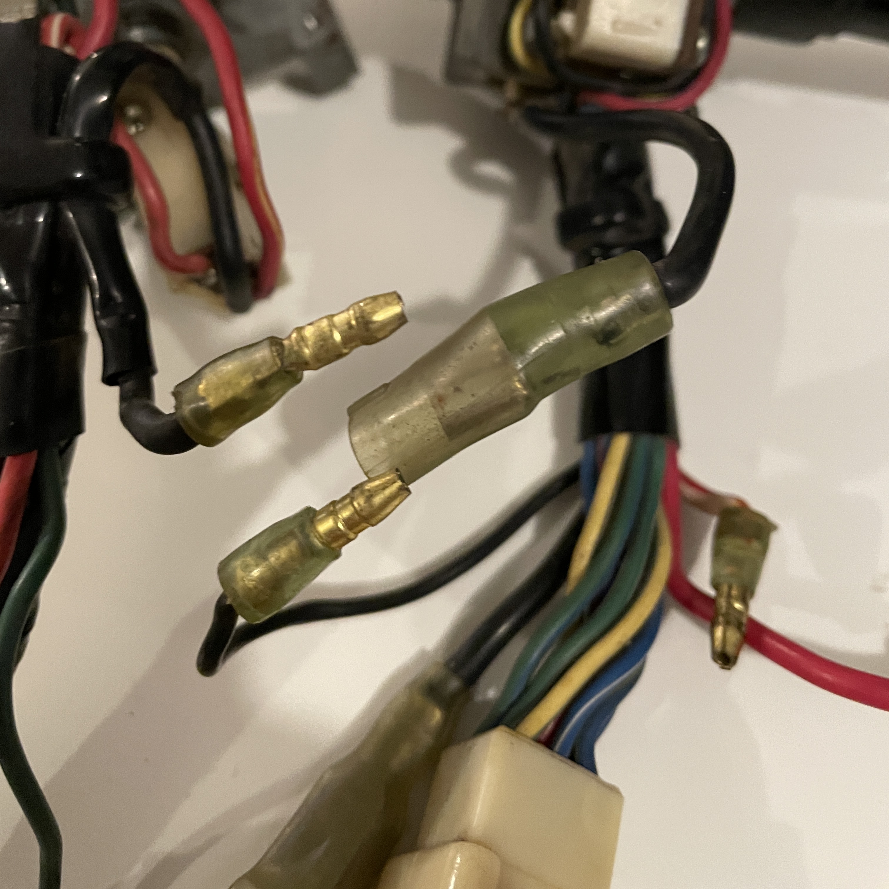
Matthew Abate replied to Matthew Abate's topic in Build Threads
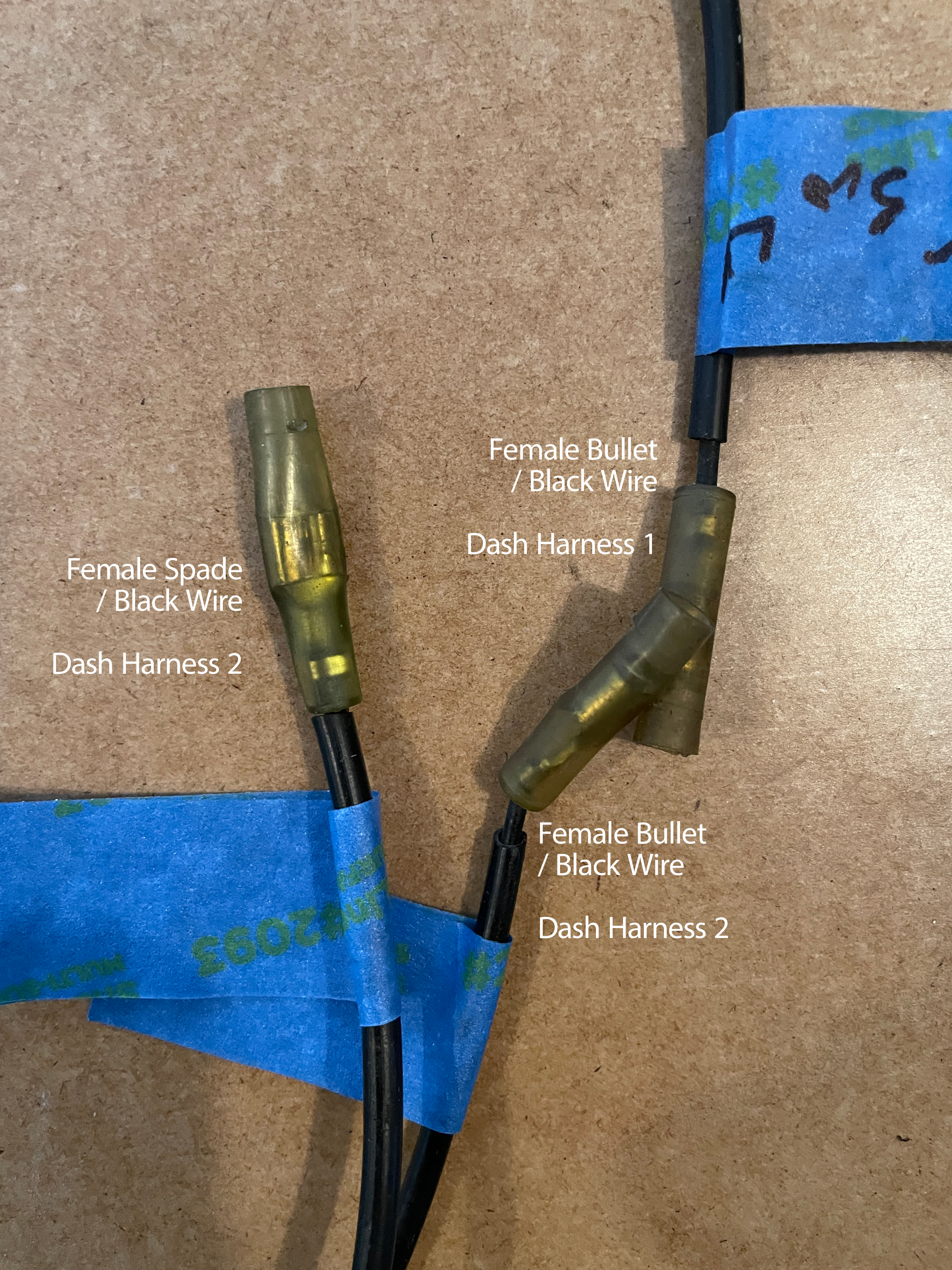
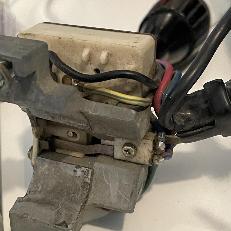
Thanks @SteveJ, That clarified some of it for me. The TS Switch that came with the car has two R/W wires instead of one and a GB wire. It's got the RB going to the GB, which threw me off. I'm wondering if it is from an earlier car or something. Thanks for confirming questions 4 & 5. I guess I will just leave these as is. The the '73 wiper controls, I have the Yellow / Blue wire switching to a Blue / White wire at the connector which goes to a splice and branches to the intermittent relay and the wiper motor, so I guess it's the same as the '74 routing you described. I guess they just don't represent that wire on the diagram at the wiper switch. You can see where it goes into the switch and them comes out again as a Yellow / Black wire on the oposite side in the photos below. As for the rest of it, these are the plugs I still need to figure out: …on the 1973 Switches …on the Dash Harnesses The Female Spade on Dash Harness 2 goes to a yellow splice that also has a black wire with a female bullet on it. I am pretty sure that is for the step light harness, because they're both spliced to a black wire that goes to the body harness and I think around to the other door switch. I am confused by this because the door switch is supposed to be two spade connectors (F&M), not one and a bullet. It's possible I have my wires for the steering lock mislabeled. The Female Bullet on Dash Harness 2 comes from the Steering Lock Switch. The Female Bullet on Dash Harness 1 comes from the Buzzer. Once I resolve these plugs I can fix the errors in my tables from before and wrap up this wiring diagram. After that I will make another diagram that has the modifications in it.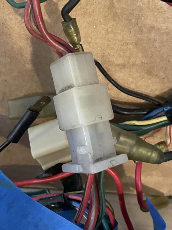

-
1973 240z Custom Wiring From Scratch
Matthew Abate replied to Matthew Abate's topic in Build Threads
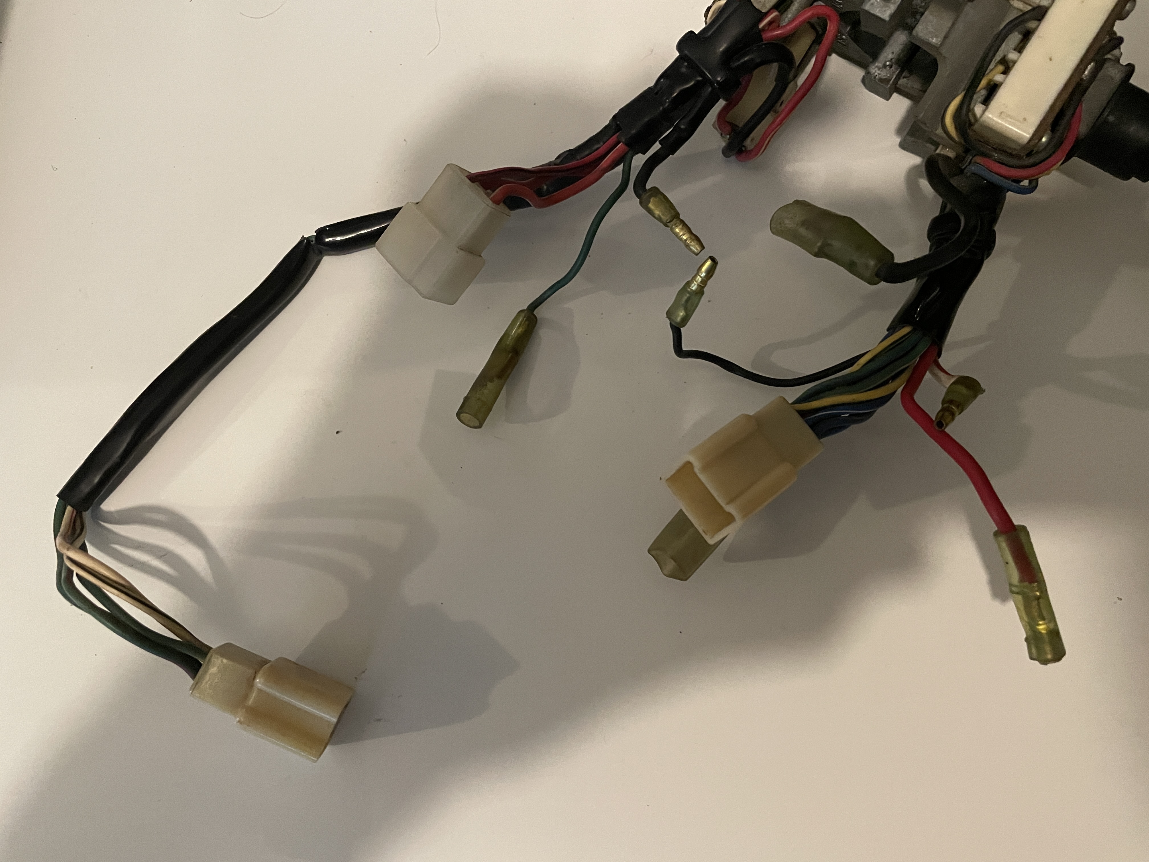
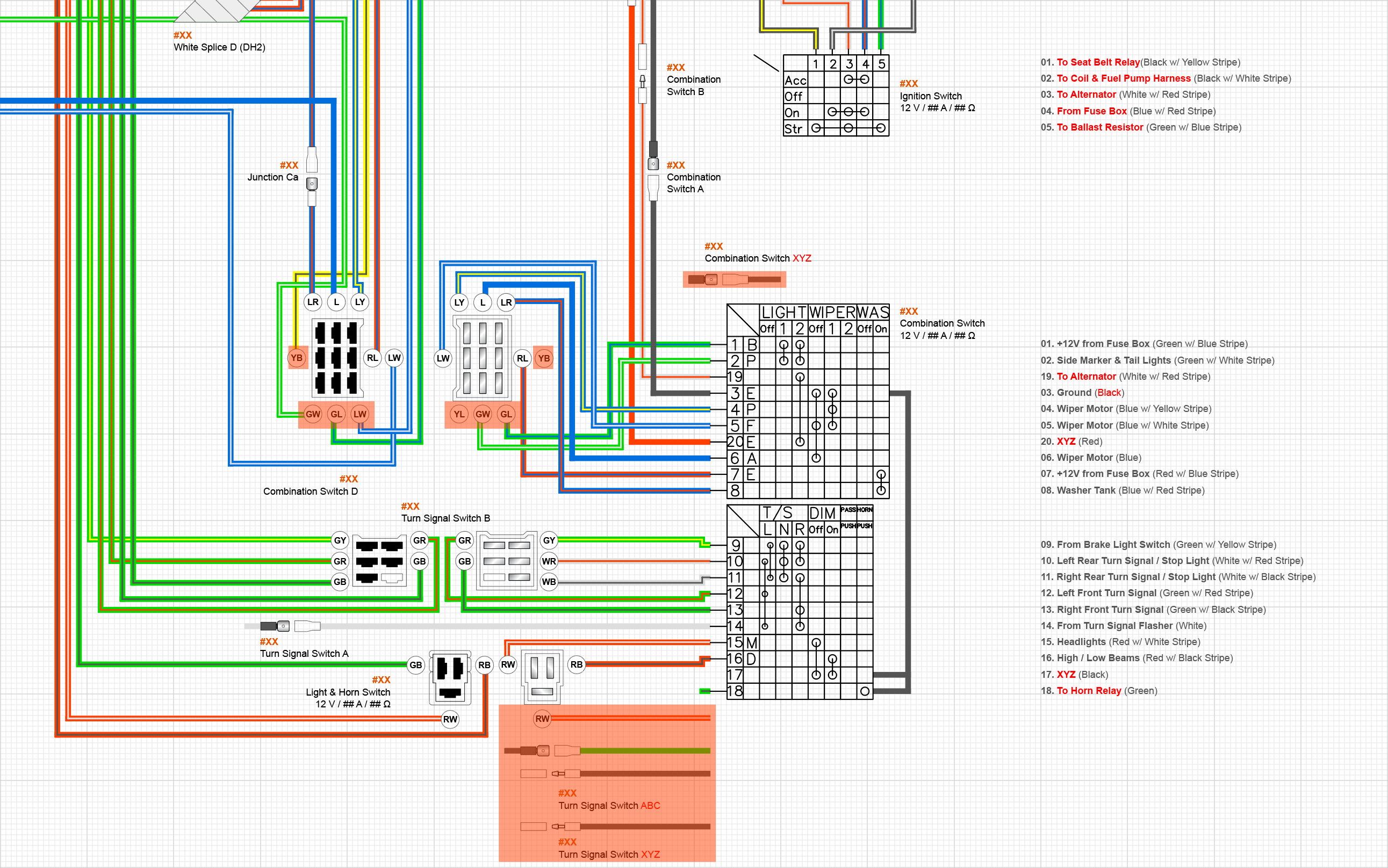
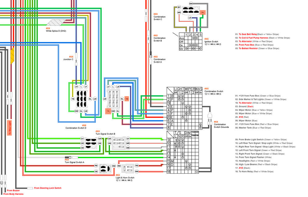
Okay, I'm getting close to being done with this diagram, and I have found a number of errors in my tables that I will fix once I have this all sorted out, but I could use some help on the current blocker that I have not been able to figure out. I am cleaning up the part of the diagram that shows how the Combination and Turn Signal Switches connect to the harnesses in the dash, and I have a few wires I cannot account for. I want to thoroughly understand this because I want to swap this TS switch out for one from a 260Z that I bought from @jfa.series1 for reasons I won't get into here. Here are the connectors coming off the switches (sorry about the shadow): 1 x 9-pin (9 wires) 1 x 6-pin (5 wires) 1 x 3-pin (3 wires) 1 x Large female spade (heavy gauge black wire) 1 x Medium female spade (heavy gauge black wire) 1 x Small female spade (thin gauge green wire) 1 x Male bullet (medium gauge black wire) 1 x Male bullet (thin gauge black wire) 1 x Male bullet (medium gauge white wire w/ red stripe) 1 x Female bullet (medium gauge red wire) Here's the diagram I am working on showing the harness and switches connectors: You can see all the things I am trying to untangle highlighted on the diagram in red: Is the Green/Black wire coming from #18 on the turn signal actually the Green wire with the small spade connector on my turn signal switch and goes to the horn relay? Do both Red/White wires on the Light & Horn Switch connector go to #15, or does the second, unaccounted for wire go to #17 and just isn't represented in the diagram? These are identical between the 1973 and 1974 switches, although the 1974 has a Green/Black wire coming from #16 rather than a Red/Black wire. Are the two black wires with the bullet connectors actually the black wires in the diagram that connect #s 3, 8, 17, and 18? If so, what do they connect to, given they are both male?I have two black wires I can't account for on the harness (one female bullet connector and one female spade connector). I had incorrectly labeled these as for the Door Switch. I am pretty sure the second black wire with the spade connector that I have labeled as "Combination Switch XYZ" is actually a duplicate of the one labeled "Turn Signal Switch A" with the white wire and connects #14 to the turn signal flasher. The Green/White and Green/Blue wires (#1 & #2) on the Combination Switch connectors are reversed from where they are on the harness connector. There is a Yellow/Blue wire on the Combination Switch connector that isn't in the wiring diagram. It comes out of the back of the white box on the switch opposite the Yellow/Black wire, which is also not in the diagram. The wire on the harness in the corresponding position to the Y/L one is Blue/White and goes to the intermittent relay, and the wire on the harness in the corresponding position to the Y/B one is also Y/B and goes to a Blue wire on the engine harness running to the wiper motor. I'm pretty sure the rest of the stuff I have captured in the diagram is correct. If anyone has any insights into what's going on here, I would love to hear them! @SteveJ @Zed Head @siteunseen

-
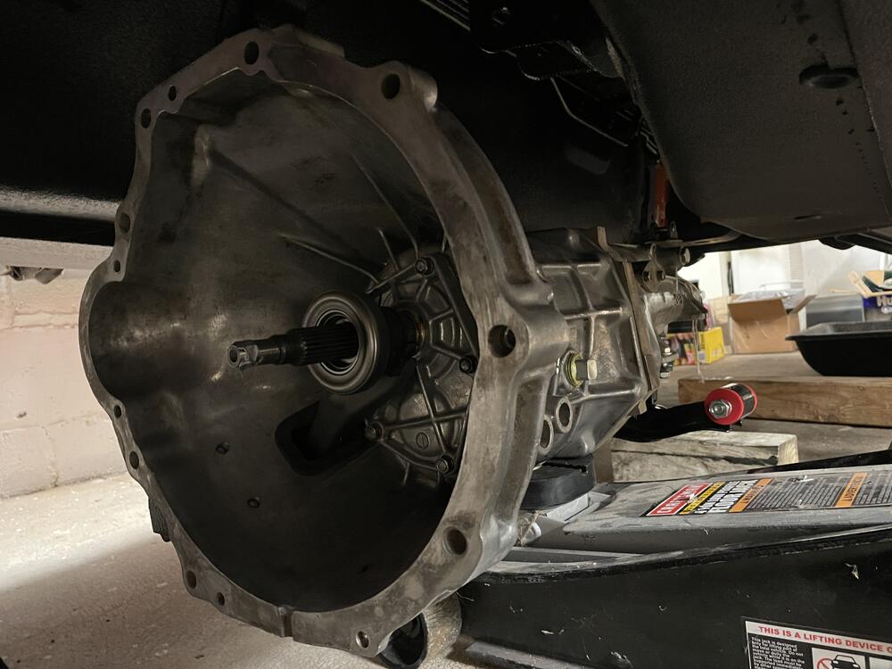
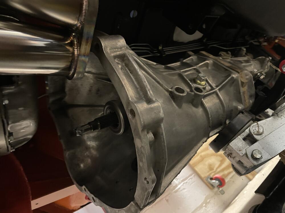
So the 280zx gussets don’t mate to the 720 bell housing. The transmission isn’t drilled at the points where they would connect. I could drill it out, but really don’t want to. I’m going to look into whether the 720 had similar reinforcing parts. Kameari makes a reinforcement, but it’s $200 and might have the same problem, plus it attaches at the oil pan, not the hard points Zed Head pointed out. I think what will probably end up happening is I’ll live without it for now and fabricate one out of bent steel in the future. Given the transmission and engine are only connected by four bolts, I’ll definitely be doing something.
-
Oh, thanks. I had assumed those were for the power steering stuff that swoops under the engine, but I’ll check those out and see if they can attach to the transmission. There are a few holes that aren’t for the plate that is sandwiched between the transmission and the block.
-
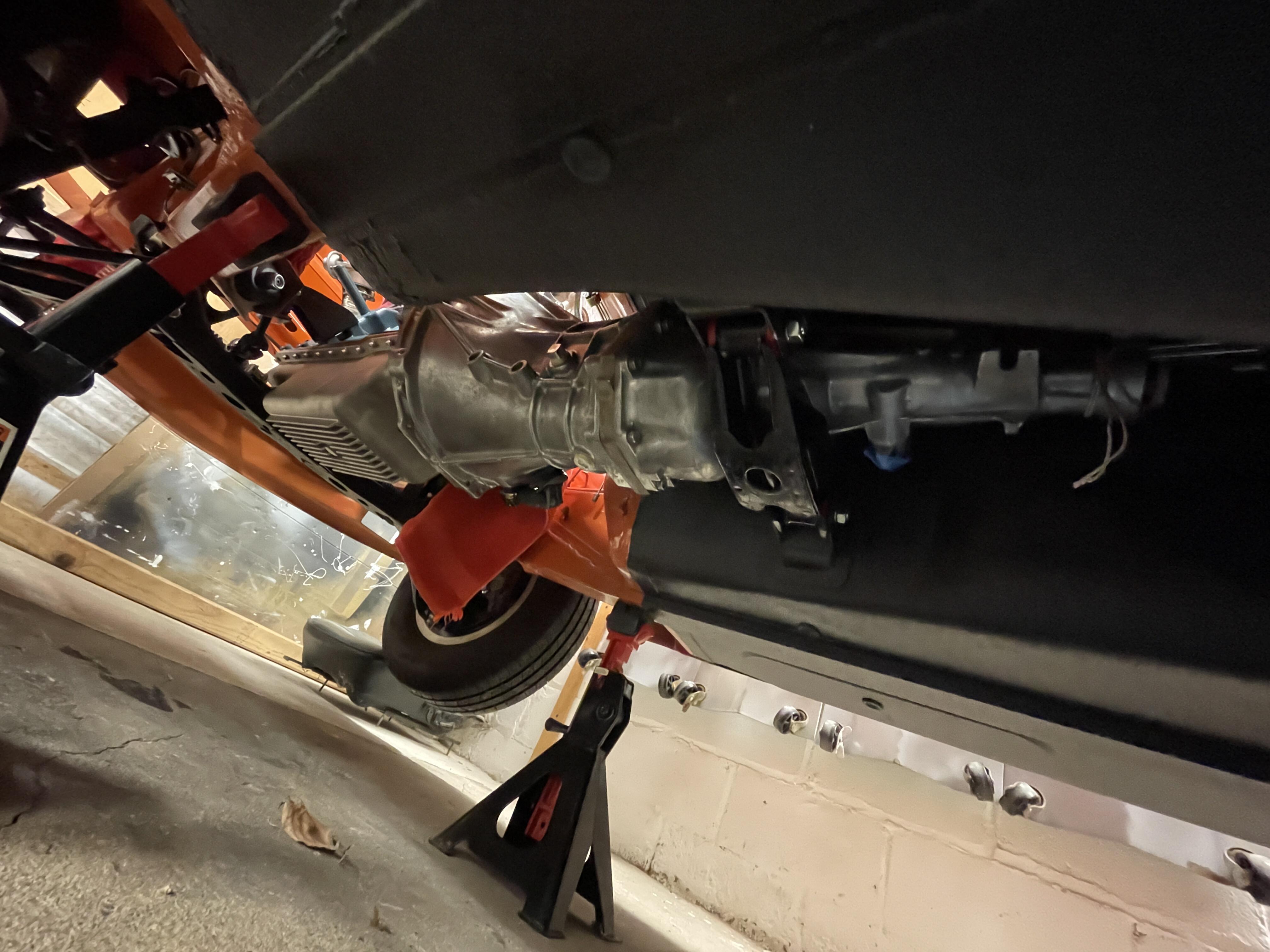
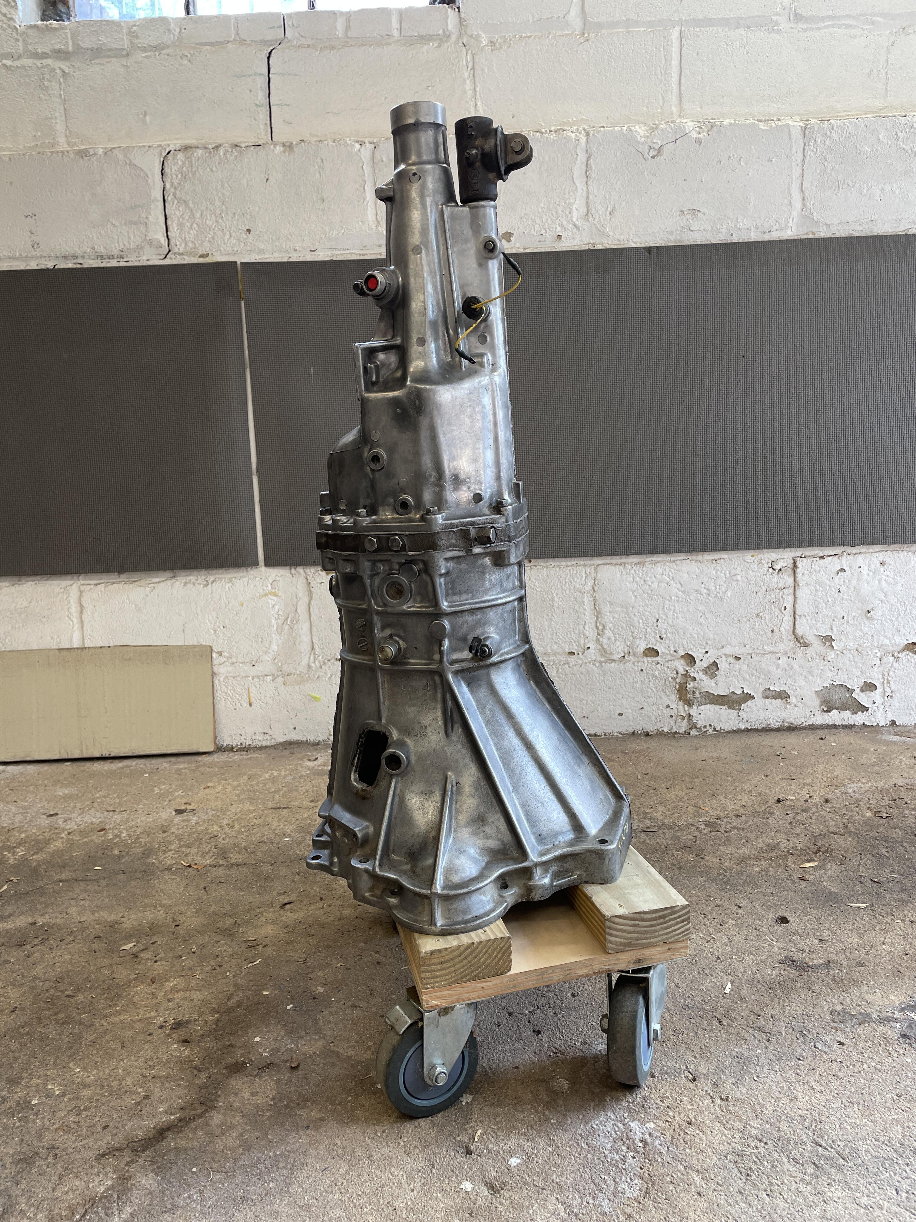
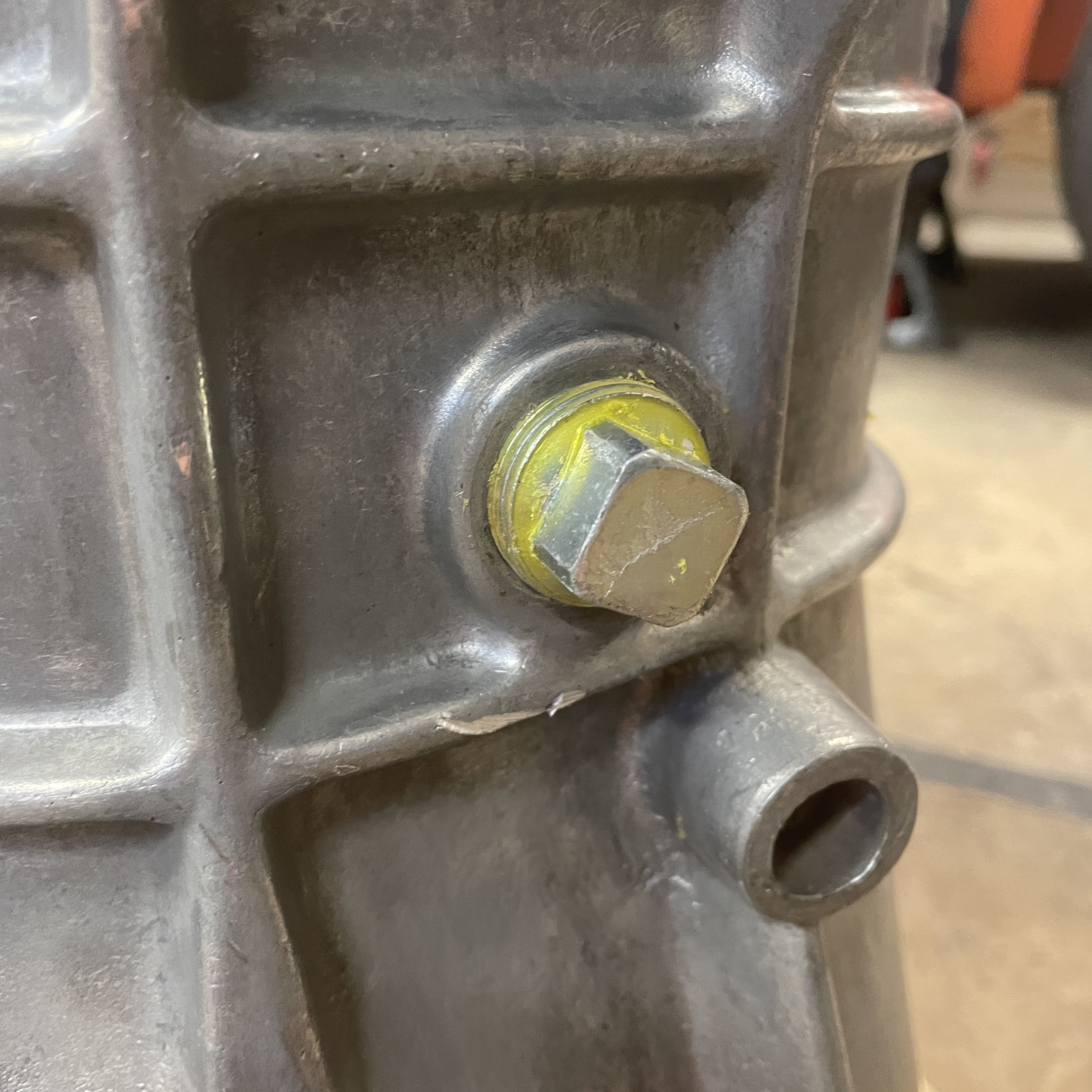
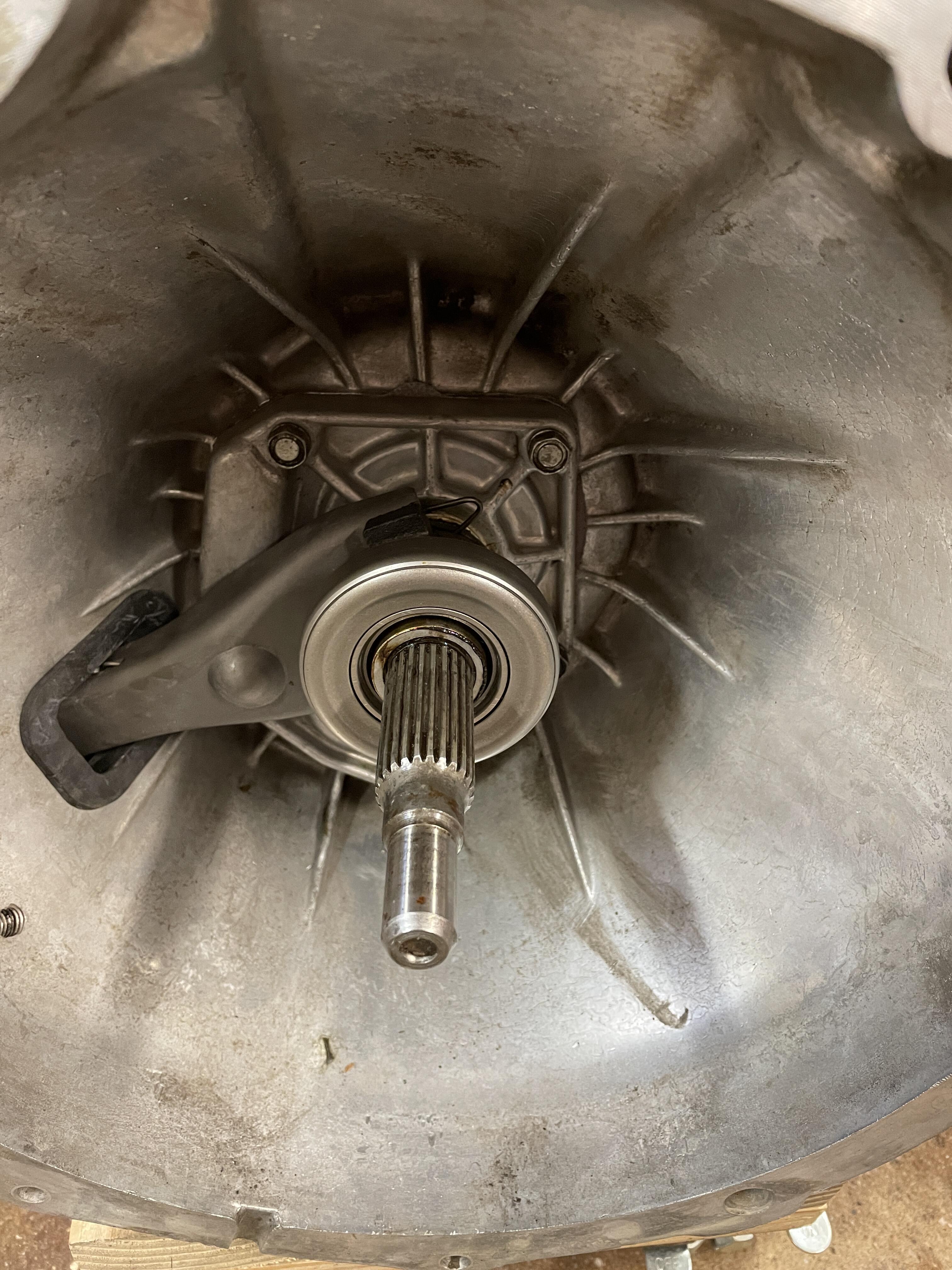
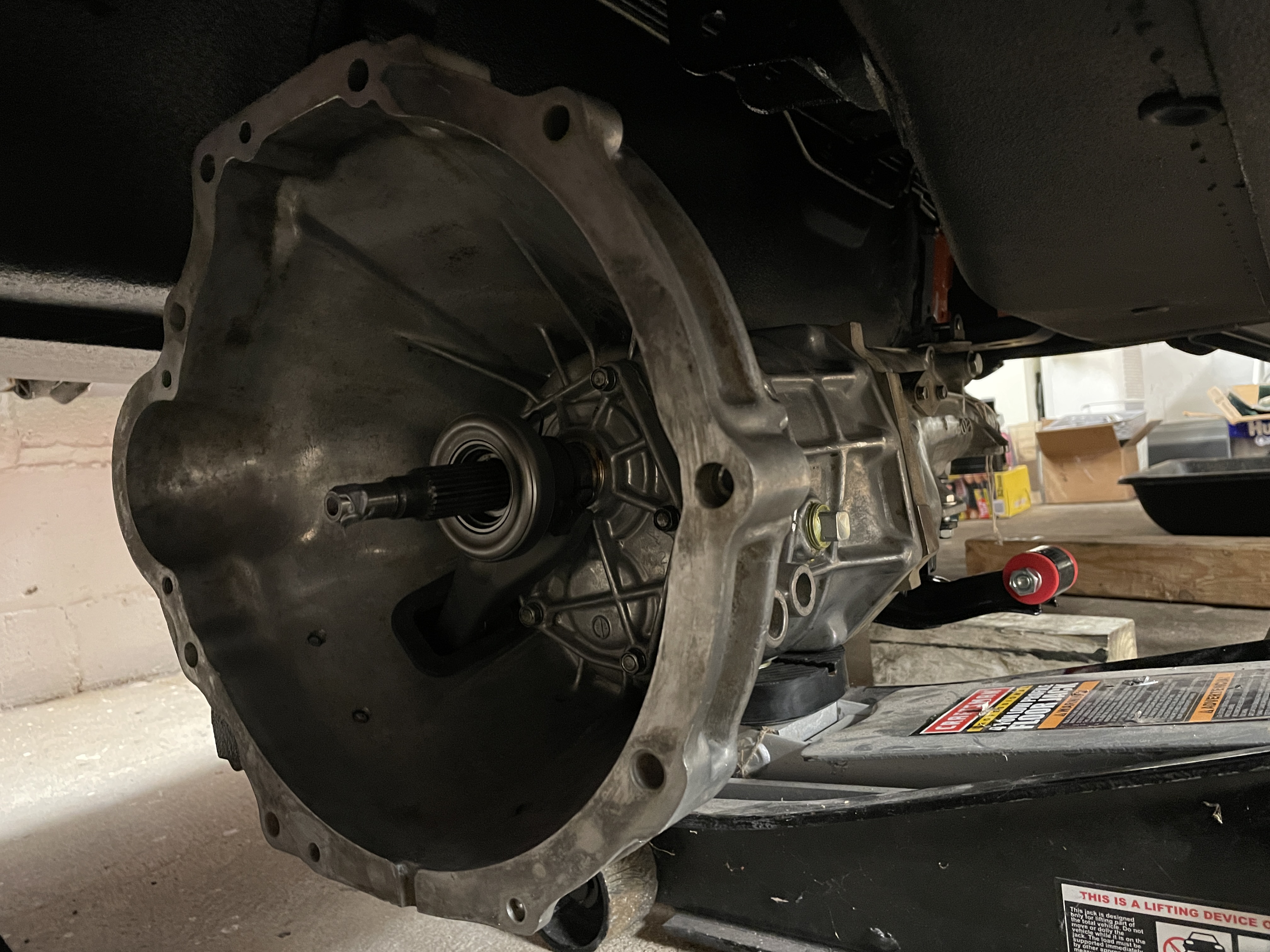
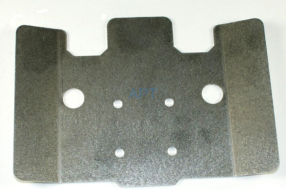
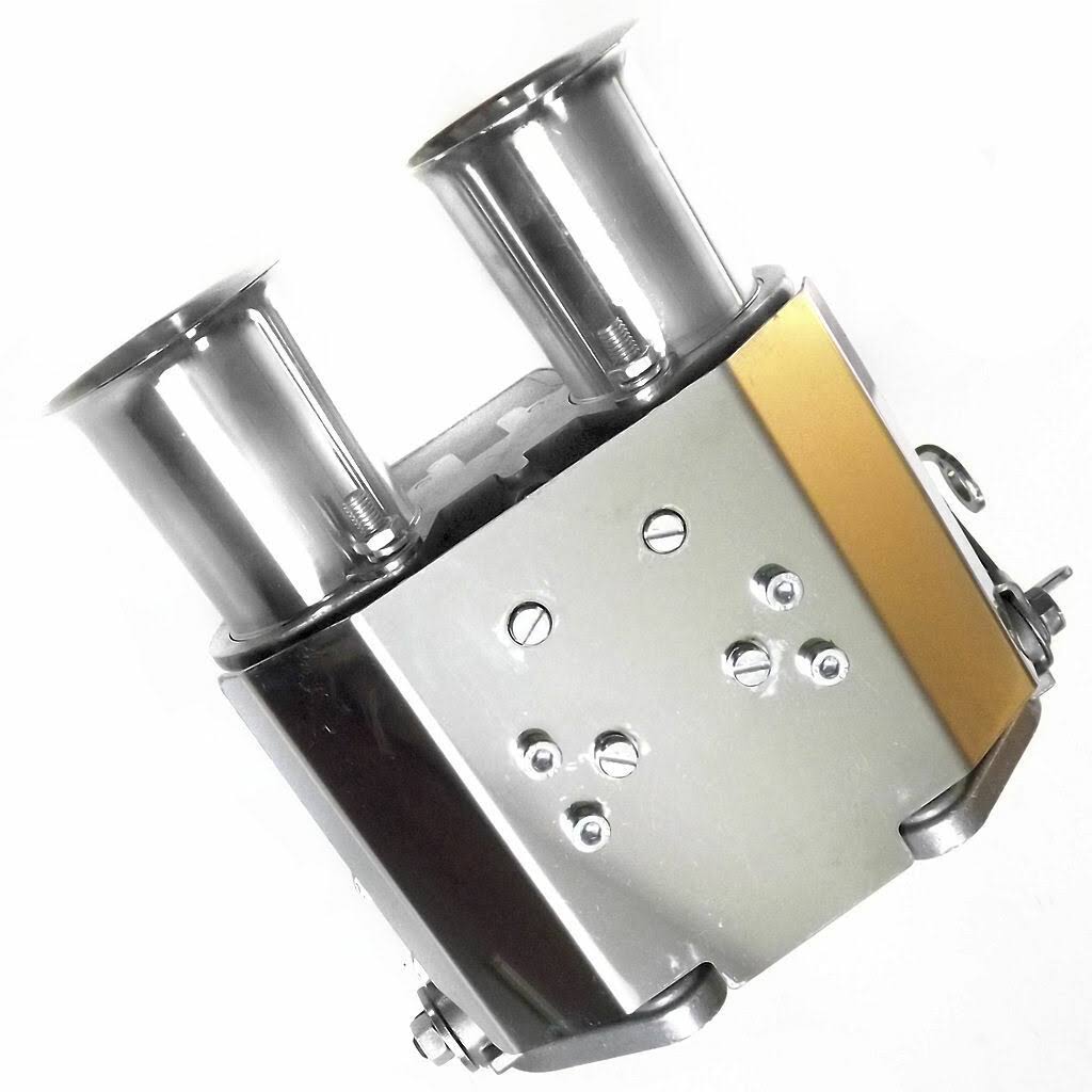
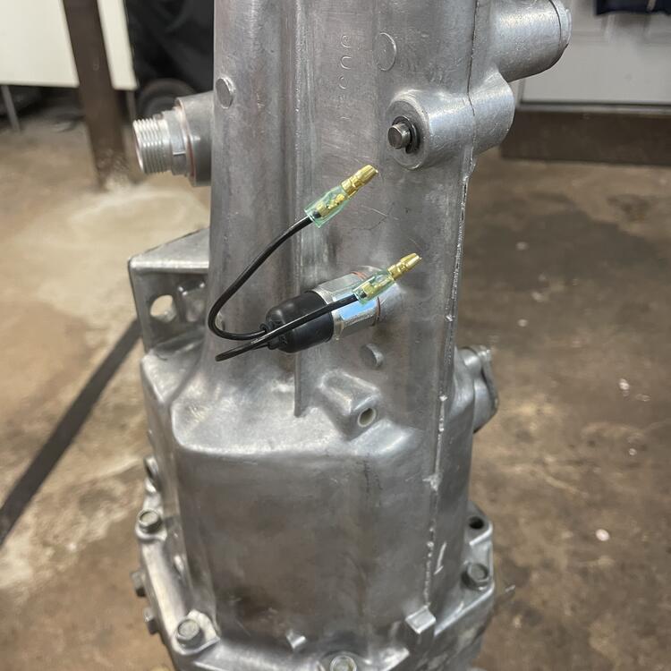
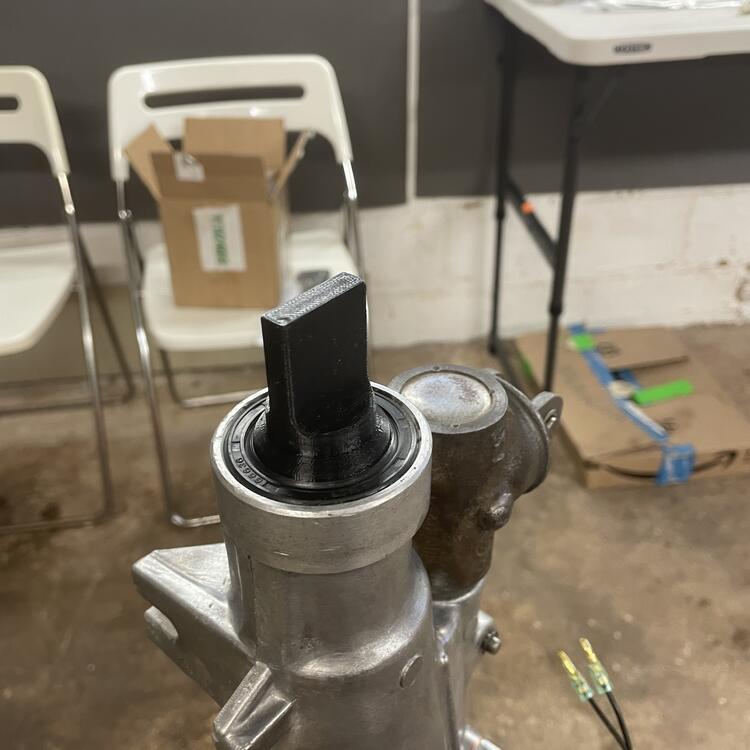
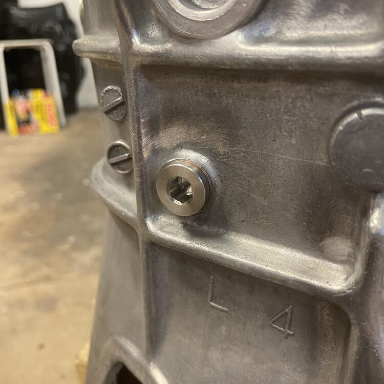
Okay. Big flurry of activity this week. As I mentioned, the SU intake system isn’t going to fit. I think I could make it fit with an aluminum spacer about a centimeter thick, but I’m not going to (or at least I’m not going to right now. I might do this as a personal project down the road.). I picked up some Mikuni N44PHH carburetors already mounted to an older style Harada manifold from Yahoo Japan, as well as a Mikuni Short-Runner intake manifold with ports on each of the six runners from a guy on the Mikuni Facebook group. After I get the carbs rebuilt and new linkage set up on the Mikuni manifold by Kyushu House (Dave Premo wasn’t available), I should be 75% to where I thought I was with the SUs. There are the questions of how I want to make the balance tube and what sort of filtration I want. I picked up the air box from the Z Club in the UK, so we’ll see how that works out. In other news, I installed my five speed! If you remember, this is a #1 case five speed out of a 1980 720 truck. I got it years ago from a yard in Idaho who pulled it back in 1983. When the transmission shop opened it up this summer they said it was nearly pristine, but I had them replace all the bearings and seals and springs anyway. I got that back at the end of October and refurbished crossmember, got a new mount and all the random bits, and installed a 280zx clutch release sleeve and the pinion for my 3.54 rear end. 👆🏻 That’s a delete for the Top sensor. 👆🏻 Output shaft plug until I put the driveshaft in. 👆🏻 240z vs 280zx clutch release sleeves. 👇🏻Installation with the wrong kind of jack. Yes I pulled the header to get the transmission in… at the last minute. And there’s the starter with a fuzzy photo of it installed. So now back to the electrical while I wait for the Mikuni stuff.


-

THIS ADVERT HAS EXPIRED!
- WANTED
- USED
I am looking for an intake manifold manufactured by Mikuni that is in good enough condition to refurbish or has been refurbished with good linkage.Ask for price
- US
-
View Advert ISO: Mikuni L6 manifold for PHH carburetors I am looking for an intake manifold manufactured by Mikuni that is in good enough condition to refurbish or has been refurbished with good linkage. Advertiser Matthew Abate Date 11/30/2022 Price Category Parts Wanted Year 1973 Model 240z
-
Speaking of heat shields, I noticed there are individual DCOE heat shields for webers. I’m wondering if they will fit on the PHHs, as well as if they are effective. I am guessing a single shield that spans all three is more effective, but the individual ones look nicer. Regardless, I now get the fun and enjoyment of figuring out how I want to set these up. I have about fifty tabs open with stuff about fuel rails and air boxes. Plenty of stuff to prevent me from focusing on wiring.


-
Yeah, I decided not to go with fuel injection because I don’t want a computer. The car is drifting too far away from a 240z already. Well, I can’t because I don’t have them in my hands, but I’ve discussed it with a few people who have PHHs on their Zs and they said I should have the same problem. The points of contact are the #2 and #5 pipes. Because the triples manifold doesn’t have the bulge for water channel I should be okay. 🤞🏻
-
Update to my intake dilemma: I am joining the Mikuni bandwagon! It’s going to be an eye watering amount of money , but it’s what I really wanted to do in the first place. Now I can get back on the electrical work.