


ramsesosirus
Free Member
-
Joined
-
Last visited
Everything posted by ramsesosirus
-
 Thanks rossiz; Which color code # would you say it is? Dark green #240, Emerald green #303?? Do you think it is the stock color, with more flake/ 2 stage? Or a totally different dark green metallic? I'd like to get some matching paint to paint the front air dam/etc... I definitely want to keep the same color that it is now...
 -
When I bought my 76 Z, I had to get it running. It would start and die every time. I disconnected all of the electrical connectors and cleaned with "Electrical Connector" spray aerosol. Had to sandpaper some of them to get a good connection. This was the bulk of the problem: bad connections between the bullet connections in the engine bay. There are quite a few of them. After this, had to remove the fuel tank, have it cleaned, and the inside strainer cut out by the radiator shop. It was very rusty from sitting. I replaced the fuel pump since the rusty gas likely was not good for it. I added a Fram G3 filter before the fuel pump. Ran great after this until threw a rod. Rusty tanks cause bad fuel flow, and caused mine to die after a few minutes.. when I was away from home... A few months ago, after installing a used engine, connecting everything, new plugs, cap, rotor, starter, battery, gas... couldn't get it to start. Checked fuel, had fuel at the engine bay filter. Checked spark at coil, good. Used timing light to check spark also, at plugs. Good. Sounded like it wanted to start. Found TDC and played with the spark plug wire locations on the cap, as the rotor was not lining up right at TDC... Turns out the Chilton's manual's Firing order is correct, however the image incorrectly shows the #1 in the wrong spot. The #1 terminal on the cap should be the furthest most towards the front of the car. My Chilton's showed it one below this... which threw everything else off. This also made sense with what saw at TDC, the rotor was pointing the terminal above what I had as #1. Just some ideas for you... HTH
-
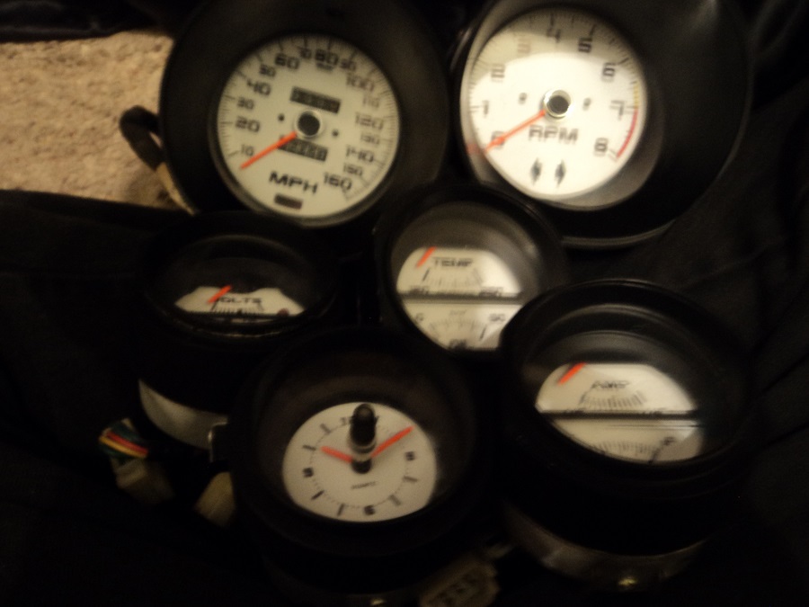
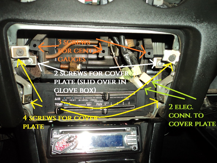
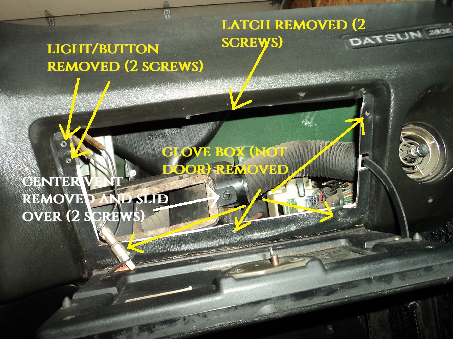
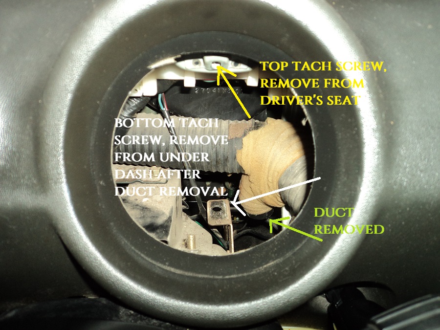
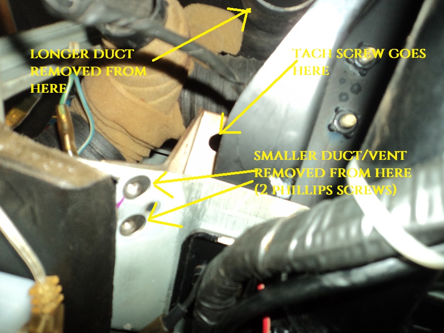
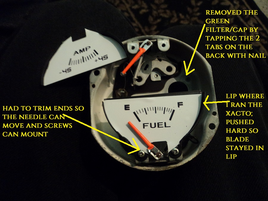
I had a set of white face overlays from the z connexion for awhile, but was deterred based on the difficulty of the task. Well I went ahead and went for it, and got it all done in a few hours without any major troubles. Sorry the picture quality sucks. I will do better for an installed picture... I am waiting on new bulbs to arrive before installing them, and making sure they work. More on that later.... For anyone contemplating this job, or removing gauges, etc.. Here is what I did and found: (I've never done this type of work before in the dash FYI) I have a dash cap/cover. I had to remove it it to get the speedo and tach out. They come out towards the driver. Luckily mine wasn't glued down to the dash. I didn't remove the column plastic cover, but I should have and will need to remove it to re-install the dash cap. It is a tight fit near the column. You do not need to remove the dash to get at the gauges. 1. Look at the FSM. it has great images, instructions and details of the dash and gauges. Also my Chilton's had the same image of the dash. 2. Disconnect battery (always). 3. Remove 4 screws on the sides of the HVAC cover plate, disconnect the wire connectors. I had 2 connectors. 4. Remove the 2 screws holding the center vent in place, they are also located on the sides. Remove the ducts from the center vent (If still connected...) I had 2, one on each side. (I try to put the screws back where they go for easy recall). 5. I had to remove the glove box to get the center vent out of the way. I could not get the center vent out through the middle opening. I removed the screws for the latch, the the light, and the glove box "holster". I didn't remove the actual glove box door. I supported it so it didn't hang down low freely. i slid the center vent to the side. 6. Each gauge has one screw on the bottom which connects the "hanging" bracket to the car. For the 3 center gauges, just remove this lower screw, massage the gauge back, and down, and disconnect the electrical connector for each. They are on tight, but came off pretty easily by squeezing the side tabs by hand. Electrical connectors are right behind the pod hole for each. The center gauge (fuel/volts) has 2 electrical connectors: one mounted and one loose) (See above photo) 7. Remove the steering wheel. Really makes the Speedo and tach removal easier. Not sure if they will even come out without doing this. 8. Remove the dash cap, if you have one. I don't think the speedo and tach will come out with a dash cover on, the cover overlaps them in the round ports. 9. Remove the screw at the top of the speedo and tach, respectively. You can get these 2 out easily from the driver's seat. 10. Lay down some blankets/pillows/old coats. Get a good flashlight and phillips screwdriver. You will be in an odd position to get the bottom 2 bolts out for the speedo and tach. Haha. Watch out for the steering wheel shaft if you removed the steering wheel. It hurts. 11. On your back, under the dash, there is one screw holding the speedo on, and one screw holding the tach on. I had to remove a duct vent to see the tach one. (The one that can be opened/closed and is screwed to a bracket under the dash, didn't know it was there before...) They bolt to a bracket and are not too hard to get once you see them. 12. Back in the driver's seat, do the tach first, reach under and push the tach forward. Undo the electrical connector. Again, same type as the center guages, I held both sides to make sure I didn't crack anything, but got them out by hand pretty easily. Push the tach out towards the driver. 13. Now the speedo. Without the tach, you can see the tripmeter cable. It has a very small screw holding it near the back of the gauge. Try not the strip it, it's on there pretty tightly. Now unscrew the speedo cable by hand. Now remove the electrical connector, same as all the other ones. Push out from the back towards the driver. (See the photos above) 14. Take a moment to appreciate what you just did. I reveled in the fact that I was holding some gauges that had not been touched by human hands in 40 years!!! Success!!! FOR GAUGE FACE INSTALLATION: There are other write ups for this around that are good. Basically you have to remove the screws holding the clear cover on. And the screws holding the faces on (unless you want to try removing the needles, no thanks...) You have press down hard on these as to not strip them. Don't ask me how I know.... I highly recommend practicing first. I had a spare gauge from the junkyard. And the kit I bought had spare overlays, depending on if you wanted volts or amps. A new Xacto blade is also a must...The overlays are close, but I ran the blade along the edges/lip of each face to prevent lifting. I had to cut the overlays in half for the 3 center gauges. They come as one overlay, but can't be installed as one, due to the needles. Do your best to get a straight and centered cut. Remember the gauge face had a divider that will cover the cut. I used the stock metal gauge face as a template, and a cutting edge. NEW Xacto blade!!! NOTE: I USED A "PRACTICE" SPARE JUNKYARD GAUGE. THE SPARE WAS AN OIL/TEMP ONE, BUT MY SPARE OVERLAYS WERE FUEL/CHARGE. THAT IS WHY THERE IS NO RED CHARGE LIGHT. I JUST WANTED TO PRACTICE. I MARKED THE GAUGE SO I WOULDN"T USE IT These overlays are vinyl and good quality. But you can only re position them once, maybe twice before they aren't that sticky. I started on the middle, since I had a straight edge cut. Then pressed down and out, towards the edges. Then cut the edges by pressing the knife into the "corner" of the stock face. It has a lip. These lips are covered when installed, so don't worry about perfection. Again, a NEW Xacto blade is paramount to get good cuts. A bad cut will tear the overlay. Even if they are not EXACTLY positioned perfectly, as long as they work it should be fine. I don't think the difference between a gas level of 10 vs 10.1 gallons will matter much. You get the idea... Don't forget to cut the hold for the charge indicator light also. I did an "X" from the back, then put the Xacto in there and turned it round and round. Got a nice round hole. You have to remove the clock hands. They just pull off, straight up. The clock overlay was slightly smaller, and didn't quite reach the edges. But it is not very noticeable with the face cover on. I also put a few drops of sewing machine oil (clear) on the clock gears to see if it will get it working. I turned the clock thing by hand, spinning the spinny thing that drives it, and it does in fact turn and move the hands, but we'll see if it starts working again... I verified that the time changed when spinning the spinny thing. This is the technical term! Haha The Speedo and Tach needles need to come off, as well as the two small screws in the center of the faces. Remember where they are at when removing, I did both of mine at zero. I did this by hand. Pulled straight up (the black round covers came off the first try...) I kind of expected the needles to break, but they didn't , and I didn't seem to bend the needle pin either. I pulled up pretty hard with my finger and thumb, then it popped off. I thought it went flying, but it had stabbed me in the finger under the nail. Watch out!.. Don't get blood on the white faces. Unless you like that sort of thing, might be a unique touch... Haha We'll see when I install how they work.. Some use a fork or similar tool to remove them, I like to use my "feel". I painted the needles orange with model car paint. Look great, dried quick. Use one of the very small q-tip looking brushes specifically for model cars. Put a piece of paper or something under the needle, over the gauge in case you miss or drip for the center 3 gauges. The speedo and tach and clock needles/hands are off, so painting them requires a steady hand and something to lean them on to dry. I used a plastic coffee container lid, leaning the end of the needle on the lip of the lid.. Installing the speedo and tach overlays is tough, getting everything aligned. But use the center hole, and screw holes as a guide. Also the speedo and tach have the brights and turn signal cutouts too. I was happy with the placement results. Not perfect, but nothing is. I wanted the turn signal arrows to be aligned more than the center screw holes. I had to pick which one, as it did not seem that they would both align exactly. With the screws back in, you can't tell. But tightening the screws with the overlay underneath will twist/distort the overlay by the screw. FYI. The speedo has a very small "needle" that the indicator needle rests on at zero. I pried it back slightly from the back, smoothed the overlay to it, then pressed it from the back, punching through the overlay. It easily punched through. I was pleasantly surprised by this. The needles go back on the same way, straight down. Don't press too hard. Don't forget to pop (or glue) the black round caps back on there. Screw the screws in. Not too tight or you will distort the overlay vinyl. I put the needles back on at zero, which I where I removed them. Some suggest putting them on at the max, then letting them return to zero. Not sure about this, we'll see if what I did worked... Main points: It's not super difficult. Follow the FSM images and instructions, they are exact EXCEPT for the center vent and the speedo/tach needle removal is not in there... The dash doesn't need to be removed. The dash cap does, if you are doing the speedo and tach. Clean/dust the stock face plates good. I have a few bubbles from specks of dirt. Live and learn... Might poke them with a needle to get the air out.... Practicing on a spare guage is VERY helpful, as is installing one of the spare overlays. A sharp Xacto knife is nearly a must have. Change the bulbs while they are out. I ordered some blue incandescent bulbs online. I don't want to rewire or mess with LEDs right now. Remove the green "cap filters" if you want. They just pop out when you tap the tabs, with a nail or something. Don't tap out the ones for things like turn signals, brake, etc...These will come out easier if you do this while the faces are out. I didn't decide to change the bulb color until later, so I will have to remove the speedo and tach faces again to get the green filter cap out. Unless I can figure something else out. I REALLY don't want to press my luck and remove the needles again.... Well I hope I haven't missed anything. It is a tough job for sure, but more tedious than difficult. Dealing with small, fragile parts like these requires patience, and a steady hand. Hope to get these installed this week when the bulbs arrive... I'll be back...
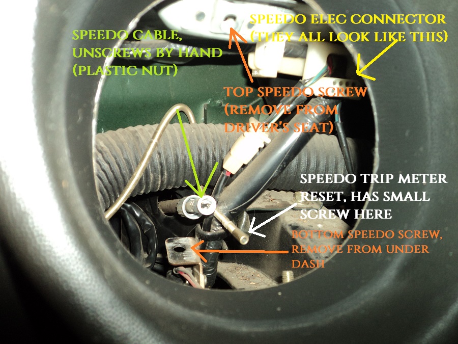

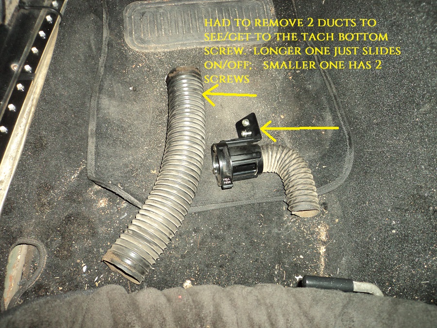
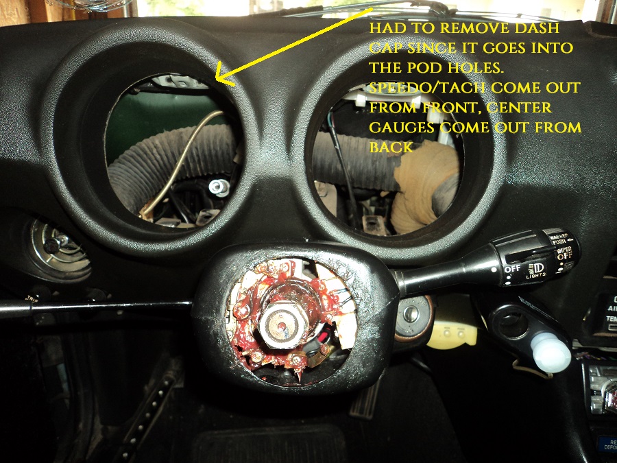
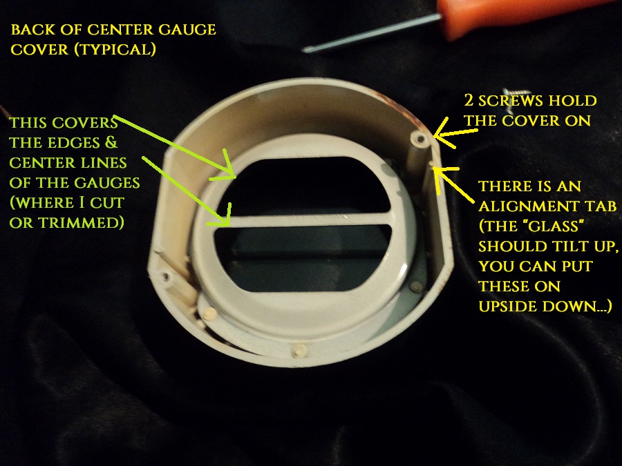

-
I just addressed the speaker issue in my 1976 280z. I pulled the rear panels since I had some 4" Sony Xplods on hand. I checked the FSM, and like others have stated, it only shows 1 speaker in the whole car, on the driver's side rear. It looked just like others have shown, with the bracket. The other side was drilled for a bracket. So it's also the 280z that was only equipped with one speaker. They are at the very rear of the car, near the brake lights. Not by the strut towers or quarter glass at all for my Z. I installed the speaker on the driver's side in the bracket, then rigged up some metal tabs to hold the other speaker using the existing holes. Worked pretty good, much better sound. I look forward to listening to the engine more than anything though! The PO of my car must have had some subwoofers, as evidenced by the wiring I found. I don't plan on going that route again, been there with some other cars, the only thing i accomplished was rattling my cat converter loose. Also had a friend with some massive 15" subwoofers vibrate his engine oil seal out. Not good. I don't think my Z would handle the vibration very well at it's age....
-
I have these mirrors installed on my 76 Z. They look great, I also have a set of the "original" metal sport type mirrors. They are very similar. These were easy to mount to the existing location. I do not believe I drilled any holes or anything. HINT: Mine started getting loose/wobby after a few years. The mirror to the mount (where you can adjust the mirror), NOT to the car itself. I was going to superglue the "pivot ball" in place, but decided to remove the mirror first. On the bottom of the mount, there is a screw that tightens the pivot ball. I tightened those up on both sides, and it's all solid now. I also like having 2 mirrors, evens out the look, and visibility. Only 1 just looks like it's missing the other one. Mine also had holes already on the passenger side, so I didn't really have a choice!
-
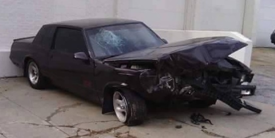
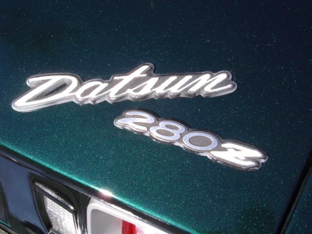
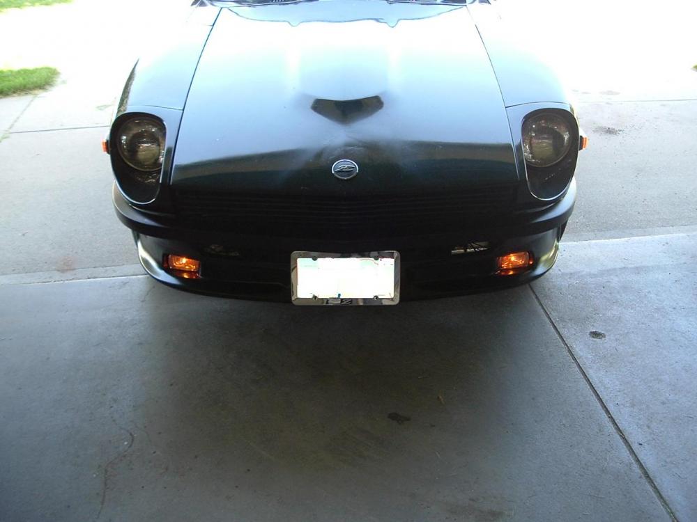
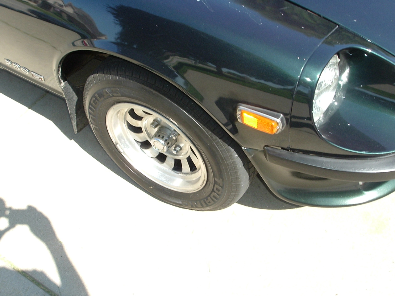
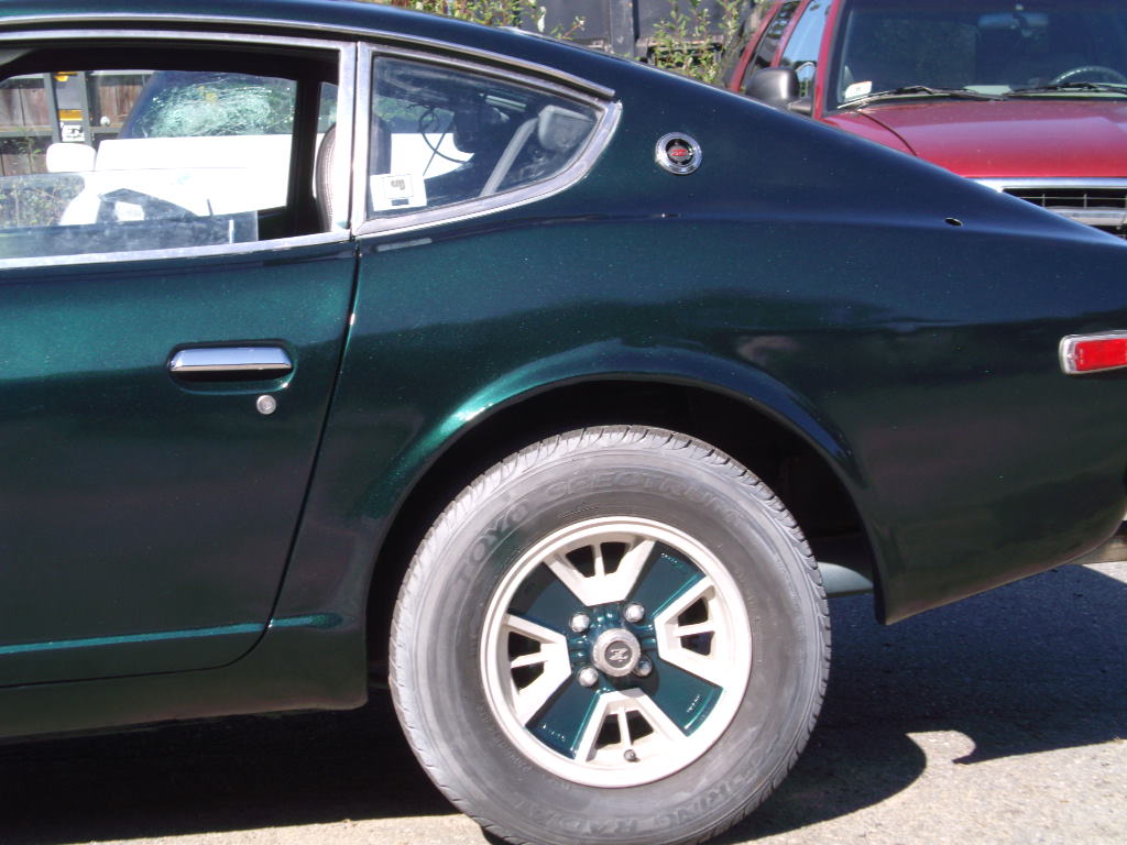
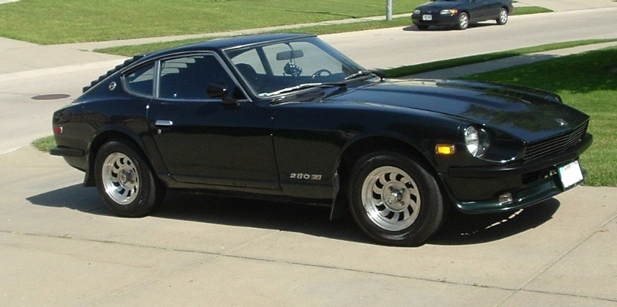
Hello Z fans, Been getting a lot of work done on the Z lately. I did some extensive searching, but cannot for the life of me determine which green paint I have. It is a 1976, but it appears to be an "early 1976" since it has the storage hatches behind the seats. No sub floor (or at least it isn't there anymore...) Engine bay and spare tire well are green, so I know it was originally green. The original paint "Color Code" sticker is intact on the radiator frame, but the code is not there: It has faded or whatever. I've tried different angles/flashlights/etc.. but cannot make out any sort of numbers at all. I've looked at the paint code sites. There seems to be several shades of green used around this time 1976. .I cannot determine which one I have. The pictures all seem different? I was thinking the 303 emerald green, but my car is darker than that. Then I was thinking the 240 racing green, but mine is a little "bluer" than that. Any help would be appreciated- Here is my car. It is a green metallic, that is very dark. In the sun it seems to turn a shade of turquoise-ish blue at the right angle, if that makes sense... The closest match that I have found would be Gary Williams' Z from the Connecticut Z Car Club. Here are some pictures of his car, which he states that he painted "Dark Emerald Green Metallic", but didn't give a code, also that specific name is not listed on the sites have found... I was unable to contact him through the Connecticut Z site, is he a member here? Here is his car with the paint that is basically the closest to mine I have seen: Thanks for any help- the paint touch ups I have been doing with off the shelf stuff won't cut it for larger areas. I spot painted a few areas just to cover some rust spot repairs.


-
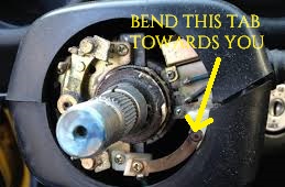
After not having an operable horn for a few years, I decided to try to figure it out. It's such a simple thing, I'd feel guilty if I couldn't get it working. Plus, you never know when using it could save the car or someone else from injury! My car is an (early) 1976 280z, so others may be different. Basically, what has to be done is: Bend the horn contact tab out further, so it always is touching the metal plate on the back of the Grant adapter. It will not contact it if you don't bend it or modify it in some way, there is a gap. The single wire that comes from the Grant adapter will need to be routed through the proper holes in the adapter plates, then connected to the middle (positive +) electrical tab on the back of the Grant horn button. My Grant button has two connectors, a center one and an outer one. The outer one is marked as ground. If you connect it to the outer (ground) tab, the horn will constantly sound when installed.(when the metal tab touches the metal, won't do anything when the horn button is hanging free) The small metal tab on the side of the horn button (not the full rinig) contacts the metal of the wheel/adapter and completes the circuit, I had to move mine below the inner coil as it had popped up one coil. It took some trial and sounding of the horn to figure out, but overall, it is fairly simple. Now my horn works only when I press the button! Let me know if you have questions, it seems like others have this issue with aftermarket wheels so I thought I'd contribute since I've gotten so much help from others on this forum.

-
Thanks for this. I have a 76, and had previously downloaded the 1976 FSM (same thing as what you posted, but for my year) And I've been reading it lately as I get my Z going again... I studied (and graduated... haha) engineering in college for many years, so I'm well versed in technical literature, diagrams, schematics, etc.. I've also used at least 5 different Haynes/Chiltons manuals-I buy one for each car I buy (read the Monte Carlo, Cougar, Camry, Predlude, 280z, TH350 one...) AND this FSM (the Z FSM) is by far the best piece of technical writing (minus some grammar) I've ever read. The diagrams are easy to follow, and it really has an abundance of information about these cars, as it should. Even has the paint codes, specs, etc... Verified that 76 280z with Auto Trans do have the R200 diff. I understand why it is so heavily stressed for newcomers (and veterans alike) to refer to the FSM. Sure, issues still come up, especially with parts swapping, etc... but wow I just really appreciate such a great masterpiece of technical literature, thank you Nissan! And thanks to members and suppliers for continuing to provide it, I'd print it out, but I think it would be about 1000 pages or something?
-
Haha I think he was sarcastically stating that you're never really done with a z car... or maybe not so sarcastically!
-
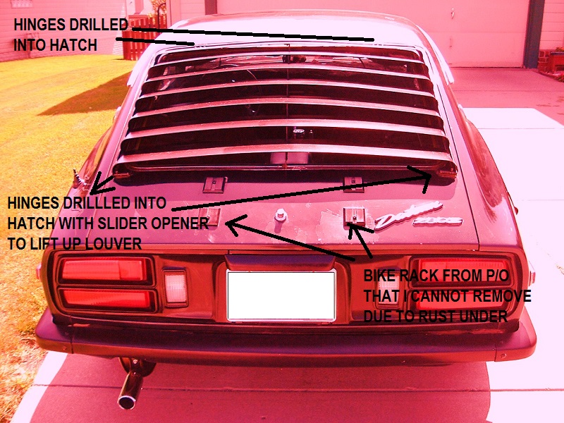
I did some silicone and rubber gasket work to the louver to minimize the clanging noises. Sorry for the color filter, I was playing with Photoshop and lost the original... I'm not sure what "type" of louvers I have, but I kind of like it. It has two slider hinges on the bottom, so I can lift it up to clean, etc... But it is drilled into the hatch in all 4 locations. Not sure there would be a way to install without drilling. I actually removed the louver once, since I do like the smooth look of these cars without them, but the condition of the paint underneath the louver brackets was not good. So I painted the louver and put it back on. Definitely helps with some sort of privacy and heat reduction, and is awesomely retro for this generation of cars. I like mine, not a fan of the other, more "square" style though.
-
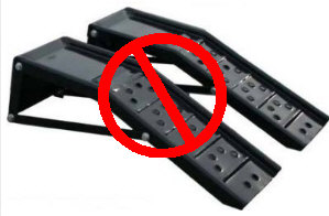
FYI I had a Harbor Freight Jack Stand split on me a few weeks ago. It was the orange 6 ton ones. I had them under my 99 tahoe during a front brake pad job, so I had two supporting one corner of the car. I didn't notice until removed the stand, but the weld along the side was splitting very good. Lucky it didn't fail. The Tahoe weighs about 5500 lbs, but I the stands should have been adequate for a corner and utilizing two. You are smart to be concerned now, before things happen. We had a young guy crushed under his car about a month ago in Omaha. I always like to use at least 2 jackstands, lower the floor jack onto the stands, then jack i up one or two pushes. I also then put the tire under the car as another added option. Even then, I don't like getting underneath cars. For the Z, especially with rusty frames, etc... I have been using a low profile Harbor Freight floor jack to jack the front up, then lower it onto some metal ramps (that do have a piece of metal between the front and back). This gives a decent amount of work space, and I don't have to worry about the frame or jackstands. Obviously everything CAN fail, but it is about minimizing the risk prior to an accident (since these type of accidents are often catastrophic). These are the exact ramps I have (from Advance Auto or something). Metal with a "cross bracket". The site was discussing why they are hard to use (move when trying to drive onto them, not aligning right, etc...) which is why they are "crossed out". I find they work better when jacking the front of the car up high, they sliding the ramps under the tires. You can position them this way, then lower the jack. HTH
-
Been working on getting the car going for a few weeks now. Was ready to fire it up last week, tried to jump it. But the battery was obviously far too gone to even jump. I didn't realize a battery could be too dead to jump, but apparently it can. New battery, new starter, new cap and rotor. Still nothng. Checked for fuel pump noise by unplugging starter terminal. Pump was running. Fuel had gotten to the filter up front (I cracked open the clamp). Checked for spark at the coil and at the plug wires with a multimeter and then a timing light. Have spark. Found TDC. Here was the problem: The Chilton's manual shows the #1 plug terminal on the rotor as being the one under the clip, which is one too far down. That is why I could not get the rotor to point at #1 when at TDC. As seen in the image below: (firing order is correct, but the distributor terminals look off to what they actually should be) After researching online, it appears that the #1 plug terminal should be the one just above or at the clip, front most in the car. Anyone else noticed this in the manual? It threw me off for awhile. Once I swapped the wires one position "up", it fired right up! Pretty smooth, but does still need some tuning and work: Lots of smoke coming from the exhaust manifold. I think I missed a bolt or two. Also it appears to have no brakes. Fluid is full, booster is connected. No pressure on the pedal though. Auto trans is slow to engage also, but probably just a fluid or adjustment issue. It shifted fine before. The valve train seems kind of noisy though, but it seems like these cars sound like that normally? Anyways, I have time before I drive it, but it way a HUGE milestone for me, as I've never installed an engine or done work of this extent before. It was also 3+ years ago since the car ran. It made me happy for a minute. At least I know the engine runs...
-
While I was looking at it earlier, the thought came to my mind that I only needed about 1/2" or so more room. Then I discovered that there are such things as fan spacers. That may be another option. I am just weary of taking more stuff apart that could potentially cause unneeded problems, especially if I don't have to. I have time to think about it though.. I appreciate the replies.
-
Cool, so you see what I mean with the spacing. So, let's say I remove the crank bolt/washer. I assume I'm not going to be able to remove those bolts with it on the car, since the pulleys will spin freely on the crank? This is a good example of some poor engineering in my opinion. A few millimeters is making a big difference! Thanks for your help, I plan to look at the car again later. I wonder how tight those pulley/sheave bolts are? Possibly a wrench or something might be able to get on there... Hmm
-
I love Harbor Freight for that reason. Great for tools you really only need once or sparingly! I am mostly interested in anyone who has done this before, who might know more in detail what I'm looking at. I wouldn't imagine the crank washer actually holds this pulley on, but it's hard to tell. From the pic I posted, that would be a very think overlap. If, however, it did, then I would imagine the spacing of said crank bolt/washer would be too long without this pulley. Surely others have put a 280zx engine into an earlier Z and know what I'm referring to here. I'm really trying to avoid removing anything I don't have to, especially if it's not necessary: these 40 year old cars tend to cause a lot of headaches with rust, broken bolts, etc... as I'm sure you are aware Thanks
-
THe crank washer is verrrry close to the bolts. The is about 1 or 2 mm between them, my sockets wont fit in between them. That is what I mean. Almost seems like I would have to use "thin walled sockets", if they exist. Thanks for the reply
-
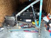
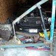
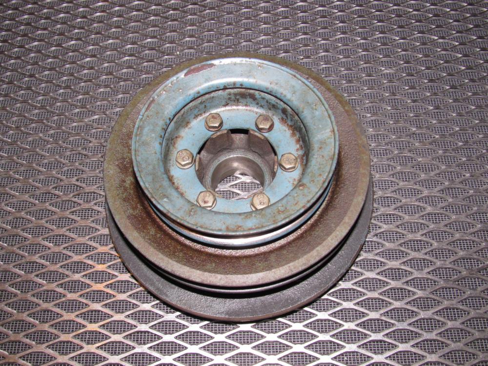
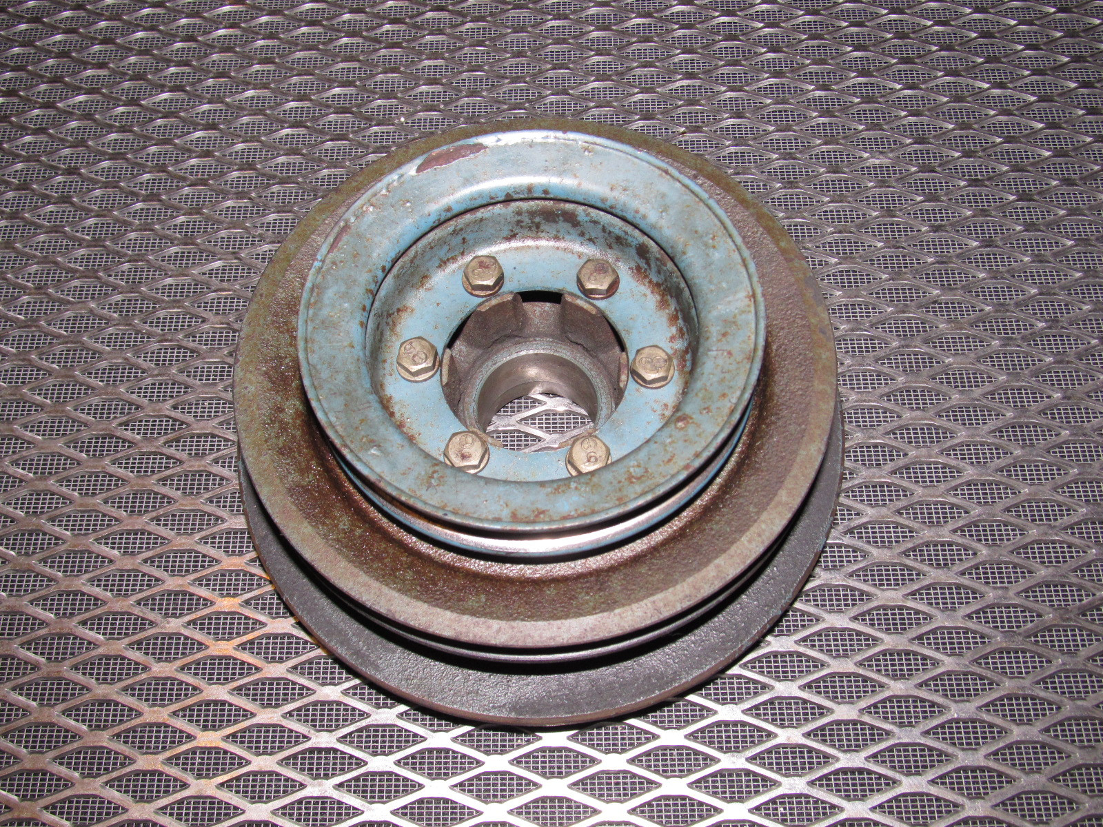
I am working on installing a early 280zx engine into my 76 280z (threw a rod). (N47 head, N/A, had power steering and injector cooler fan) It has a power steering pulley on the crankshaft. It has bolts holding it on, but there doesn't seem to be much room to remove these bolts while the pulleys are still on the engine. I need to remove this outer pulley for fan clearance. My 280z fan won't install with this pulley in the way. I'd like to not remove the crankshaft bolt. Also, will this pulley even come off after the 6 bolts are removed? Or is there a large washer behind the crankshaft bolt holding it on? Would removing this pulley afftect the spacing of all of this?? It is NOT a 280zx Turbo engine, which I've heard the power steering pulley cannot be removed. My other option is to look into an electric fan I suppose. This is the part in question (not mine, mine is on the car...) This outer pulley runs the power steering pump on some (all?) 280zx cars. It needs to go for the fan to fit. The FSM for ZXs isn't clear about if this pulley alone can be removed while the rest stay on the crankshaft.
-
The extractors won't turn at all. Feels like I would break them if I applied more force. Basically, drilling into the aluminum is ok/required to upsize the bolt, correct? What is behind this stud (the front most exhaust manifold stud, under thermostat) oil passage, coolant, etc.? Just found out I need to remove the power steering pulley from the crank so the fan doesn't hit it. (280zx engine). I hope those bolts don't snap...
-
Yes, there is a lot of info on repairing the common snapped exhaust stud bolts (the front and back ones) but I cannot decide which method to take. I have attempted to drill out the bolt and remove with extractors, but that didn't work. So I have drilled it out further. I have used a 1/4" drill bit to drill out a hole in the stud. It does not appear I have gotten into the aluminum (a magnet picks up the shavings). AND I haven't gone too deep yet. I would like to use a helicoil for this. Should I drill larger than the stock hole, ie) INTO the alumnimum head?? The hole I have now (1/4") would correspond to a M6 x 1.00 helicoil kit. I know the stock bolt/stud was M8 x 1.25. I'd prefer to not drill anymore if possible (don't want to ruin anything). Will and M6 hold up for awhile? Or should I just drill into the head for an M10 bolt, and will this fit through the stock exhaust manifold flange hole? I really thought about just leaving the broken stud, since my old engine's rear was snapped for years. But this one is under the Thermostat housing, and I've read it can affect the sensors, and therefore the ECU and fuel mixture OR melt the cap and rotor. Not to mention, I am trying to eliminate the fume smell as much as possible. Never done anything like this before (first engine swap), really just want a running Z again at this point. I will say though, that I'm a decently skilled and experienced "mechanic" from working on my own cars. Thanks for any help~
-
Darn I think the single green wire sensor in the second pic is for the fuel injector fan which the donor motor had. That would make the donor motor a 79 I believe.... Man I hate rusted, broken bolts. I'd be ready to start it up if it wasn't for them.
-
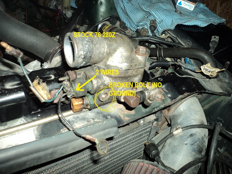
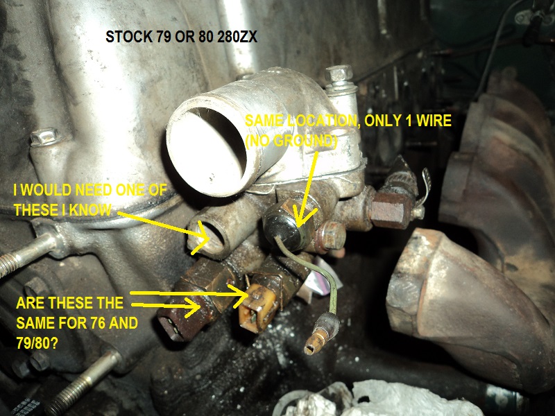
Thanks for the reply Zed. Here's some pics. Stock from 76 280z: has broken bolt that is stuck in housing where ground went. The part that threads into the head is still on the other side, but bent and stripped (so I was trying to use the donor engine's Tstat stuff) Here is the donor engine's tstat gear (engine must have been either a 79 or 80 280zx? Had an N47 head with diamond exh ports) This one has a seized bolt in the housing, but is not broken or stripped. So I was going to try to spin the whole housing into one bolt, silicone it, then insert the other bolt. There's no way the sensors are unscrewing from either of these housings....
-
My stock 76 had a 2 wire water temp sensor in the thermostat housing.. I plan on using the housing from the donor motor, which was from a 78 or 79 z or zx. Are all of these sensors the same? I noticed the water temp sensor had 2 wires (1 bullet, 1 ground screw) on my stock one, but the donor one only has the bullet connector, no ground. Will this work? Is it internally grounded? Thanks
-
I agree with all of the above; Mine would barely idle without dying until I cleaned all the electrical bullet connectors and made sure all vacuum hoses were either connected or capped. Also, mine later began running rough and sometimes dying when hot. Turned out to be a clog in the fuel tank that seemed to settle after warming up? Had a shop cut it open, clean it, remove the stock "screen" that gets clogged/rusted. Nice thing is mine (all Z's?) have a drain plug in the gas tank. That's some good engineering foresight. Could also be fuel pump or solenoid?
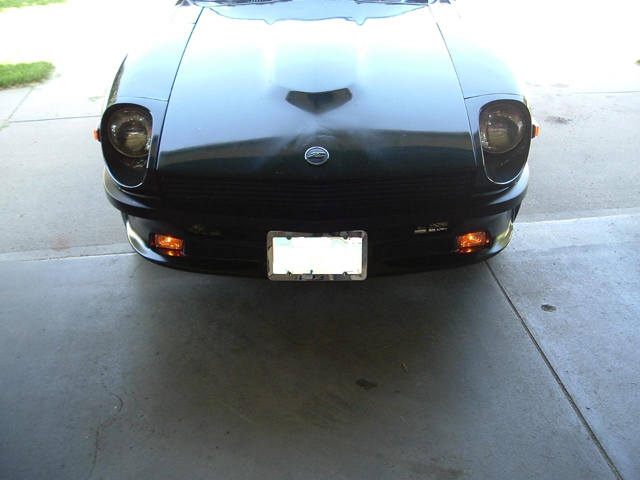
I thought I'd share this mod that I did, I really like it. I didn't like the look of my front air dam without lights in the cutouts. But I didn't want too much going on in the front. So I custom-hacked a set of fog lights to work as the turn signals. And then used a 240z grille to replace the stock grille and the stock turn signal locations. I like it


Important Information
By using this site, you agree to our Privacy Policy and Guidelines. We have placed cookies on your device to help make this website better. You can adjust your cookie settings, otherwise we'll assume you're okay to continue.