Everything posted by Packerz
-
Power antenna wires connections
Head unit is Kenwood KDC-BT330U. “All else fails”??? <- Is this for me? Can you determine if I am at least correct on (3– wire leads) connections from your Harada schematic to ‘77 factory wiring diagram? I believe the antenna lead from the Kenwood must be either pigtailed onto one of the three wires or just disregarded when using Harada unit. Guessing that this wire only have 12v power when head unit is “on”?
-
Power antenna wires connections
Thanks Zup! I apologize that install schematic has also got me confused (Not Difficult w/ Electric! ?) May I make a stab at this by me supposing: green bridged wire connects to blue/red-stripe 12v from ign. Switch; The bridged red connecting to blue/white-stripe from fuse box/battery 12v; but I can’t trace solid blue out from factory wiring diagram to determine function if it would connect to single red from toggle switch. IF I have these three color wires from factory wiring connecting to three color leads from toggle switch correct...Great! However, what happens to the “antenna”-labeled wire exiting head unit? Is it just ignored “as the odd guy out” 4th wire to nowhere and left unconnected or is it spliced-in with another of the factory wires? Sorry to be so dense. I hope I have color wires matching correctly....please advise if correct or which combo’s get it correct! Thank you!!!!! Doug
-
Power antenna wires connections
Thanks Mike! The ‘77 wiring diagram shows these 3 (blue & blue-striped) colored factory wires. they are visible from factory wiring harness as (3) leads to be connected with the (3) wire leads from back of toggle switch. Therein is my mystery...which one of the toggle switch leads ( red-pigtailed, green -pigtailed and the single- red wires) matchup/get connected to which of those factory wires. Can anyone identify the correct color wire combination connection? Does anyone recognize mfr. of this antenna by way of six blade wire set up from the back of the toggle switch? Thank you!
-
Power antenna wires connections
I am reconnecting my existing aftermarket (brand?) to an upgraded audio system. All hookups were disconnected over a yr. ago and I have no installation guide to refer back to. I am trying to remember which antenna toggle switch wires connect to factory blue, blue/red stripe and blue/white stripe wires. The toggle switch has six connection spades and three different color wires: red, green & black(antenna already grounded to body, near antenna so just leave black wire disconnected or make another body ground under console?) . **I will attempt attachment photos of toggle switch which is worth many,many words description.**. As simply described as 2-reds and 2-greens each color “jumped” to diagonal&opposite/upper/lower spades and then each color pair pigtailed our to singe red or green connection lead with another single red connection lead (directly opposite black spade/wire) three connecting wires to connect to the three factory connection lead wires ( those 3 colors of blue). Which three color switch wires connect to each color factory wire? Please help me solve mystery (re)connections. Thank you! * forgot to ID single antenna wire from head unit that was never connected because of toggle switch “up, down and hold” desired feature.
-
240Z power antenna
I’m nearing completion of my audio system consisting of Head unit, Amp, speakers w/ crossovers I my 77 280Z. I have done a “sound test” just to hear system before putting everything back into console (what fun?). Cd source sounds great but now I must hook up the radio antenna. I am using (used with former setup) a power telescoping antenna working off manual toggle switch that allowed antenna to stop in position as well as up/down. However, since the whole system was apart/disassembled for over a year, I can’t remember how the old system connected to factory wiring (same antenna) to repeat with new system... 77. factory wiring diagram shows solid blue, blue/white stripe and black ground to power antenna. (No blue/red stripe anywhere in loop...240 Z different?). What is most confusing to me is antenna has power wires 2-reds, 2-Greens and the black ground (that was grounded to metal under hatch deck). What are/why the double sets of red&green wires and which combination would go to solid blue (power from the the ignition switch?) and which to the blue/white stripe (unknown function and/or power source)? The back of the toggle switch has the same 2-red, 2-green, black ground wires. How to connect each end of this antenna-toggle switch circuit to blue & blue/white factory wires?. Anyone used this antenna type wiring? Please help me solve mystery...install sheet long gone and can’t remember mfr. thank y’all!
-
Early 74 260Z bumper conversion to 77 280Z
Perhaps last question- did 74 260 use same single threaded body mount as a 77 280? If so, In the same spot? Thanks!
-
Early 74 260Z bumper conversion to 77 280Z
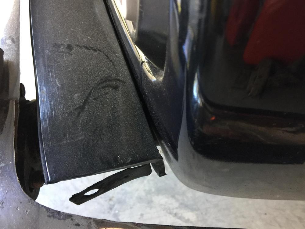
Conedodger, I don’t want to beat this thread into the ground, however, I still have questions about how you bolted (?) the rear floating sides to a 280 body. Did you keep filler rubber 3pcs. & use/keep the 2 outside rubber trim pcs? Did you use anything in between back of bumper and body? How did you bolt bumper into the body...did you drill a hole through the bumper face and run bolt on in to the body...my rubber trim pcs. won’t allow a bolt head/cap under them. On each bumper (about 4” from end) I can feel a small,short kind of plate inside the bumper with two (6mm? sized) holes in them but I have no clue how to use them in any kind of bolt mounting into body....not to mention the fact that these small plates w/ holes are already forward of threaded hole and will only move even further forward if entire bumper moves forward in potential shock compression. Trying to keep my questions and posts shorter but I don’t get the missing link of necessary bolt-ups ,into or away from, the back of bumper and then bolt thread into body (can’t visualize using the 280 “mount hole” for anything w/out some offset insulator-kind of item. This would still puzzle me in any custom fabricated conversion insulator/bracket. What am I not seeing how you have accomplished???
-
Early 74 260Z bumper conversion to 77 280Z
Wow! Great info. Did you do this strut compression and keep the 3 rubber fillers on each bumper? Most importantly, what did you do for side connection (s) to side body?? Were you able to use just the single threaded bolt-to-body mounting? What conversion did you use or make for that 3-4” gap connector??? If I get that item for rear bumper, I’m back in business! Th front bumper will need side connection also but it is much more stable than the rear’s wide gap and long “floating” sides. I am super anxious to hear the most important piece of your “how-to !!! Thank you??. Doug
-
Early 74 260Z bumper conversion to 77 280Z
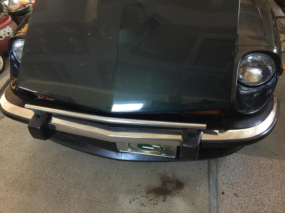
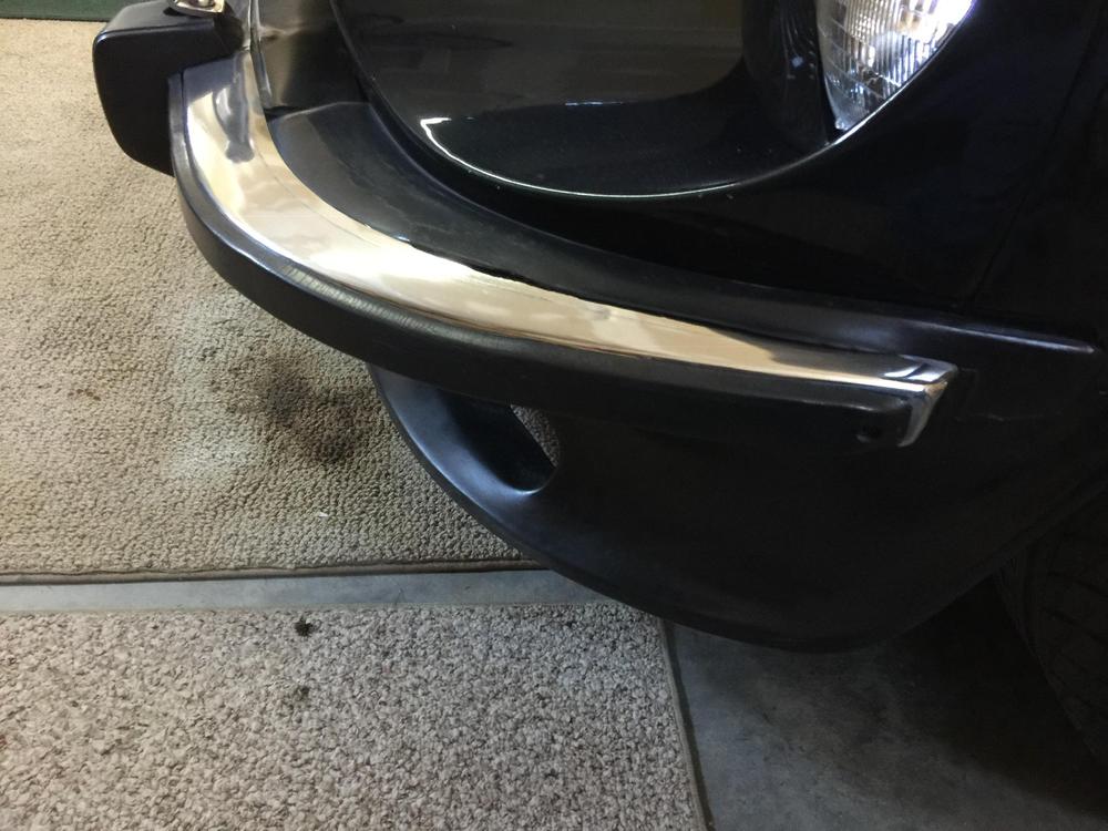
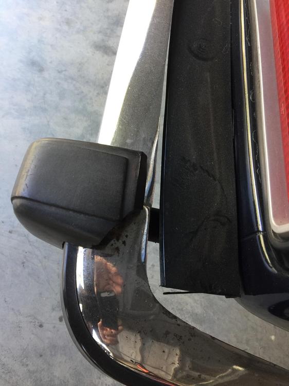
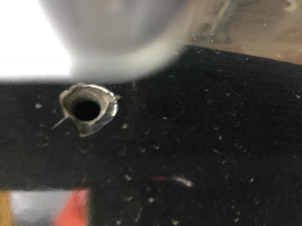
Maybe these will help. Front bumper: Hard to visualize if Compressing front bumper strut allows lining everything up by pushing entire bumper/filler/side rubber “cap assembly back toward body...where to drill fluid release hole in shock? Even so, there will still need some type of transition pc to fill gap between mounting hole in bumper (hidden behind rubber trim with 6 small molded-in “rivet-Type” screws) and some potential bolt thread hole in front body metal.... hard to figure out how any kind of bolt could be covered by those trim rubber though? Rear: please note last four photos. Shows current “attachment” w/ driver-side shock pushed in....result of someone... never mind?. Compressed mounting on that side leads me to believe bumper and filler will line-up Ok in center when passenger side shock is (properly) compressed. Here comes the However, notice the large gap on sides...even with some forward movement of entire bumper while trying to avoid near contact with wheelwell raised lip...still results in a 3-4” gap between backside of bumper and (closeup photo of threaded mounting bolt “hole” in my 280) body. This is the most problematic issue in a finished conversion for me. Any conversion pc. must allow for the offset mounting points existing between 260 bumper and 280 body (in any bumper position, using existing filler or trying flush fit . Is this something any 240/280 conversion product could be easily modified to accomplish? My sincere thanks to this forum, I do appreciate your interest, input...and patience. Doug
-
Early 74 260Z bumper conversion to 77 280Z
cgsheen1: thank you. I have most, if not all the body-to-bumper pieces already. Currently, bumpers are just bolted to the 280 “crash shock” plates with two accessible bolts...an OK arrangement just to hang them. However the sides are just kinda “free floating” because I could not use the 280 body mountings. I never got any 260 side mount brackets (purchase did include front override bar and fairly decent rubber trim appearance and filler pieces). Therefore, I don’t have “donor” 260 braces to try and fabricate some small conversion piece at the body mounting ends of a 260 bracket to my single bolt 280. These possibly could be the easiest thing to have fabricated ... could anyone on this forum do this for me at a fair price? I would have to attempt sourcing good used early 260 brackets F&R... but potentially bumper distances, fillers fit, AND all mountings line up and direct mount to my 280. With my luck, that might seem the easiest but...would not be the best/practical/ reasonable $$ path....?. Any input on this? I think you are absolutely correct in your last post re: pushing sides to far forward by simple shock compression. Kills that Thanks Zed, Yes, I could either source used 260 bumper support braces to convert, taking bumpers (brackets)and car to some type of metal fabrication shop & sharing some visualization of goal. Asking them a fixed price for creation of a conversion or just building whole new brackets w/necessary side mountings. Asking them (no idea of how to identify trusted source) if they would create a “one of a kind” 4-pc custom job...for some “reasonable” cost. Perhaps only way to determine cost/ability of ever using existing 260 stuff-or is there some Z club member doing metal fabrications (or local person/place close to WNC area) that someone could refer me to and discuss how-to? I appreciate all the input I have received and truly trying not to discard any offered options. Trying very hard to remain hopeful of some positive $$ resolution before accepting my 260 bumpers only useful for 260 replacements and no conversions value! Only source of buyers=260 owners? Very hard to swallow until all experiences and input asked... My Thanks to all! Doug
-
Early 74 260Z bumper conversion to 77 280Z
Hi to all! I am trying to find a source that would enable me to make a direct bolt-up of my set of early 260Z bumpers to my 1977 280. I can find lots of conversion kits to mount 240Z bumpers, but didn’t the early 74 260 bumpers sit slightly further from the body than any of the 240’s? If so, wouldn’t the 260 mounting bracket be slightly different (longer?) than any 240? I can only find 70-72/73 240 style to 280 conversions with “some fabrication necessary” forcing the user (me ?) to bend/weld modify and I’d have to have this fabricated =$$ and trusted source...Doesn’t’ anyone make a conversion bracket expressly for an early 260 to a later 280 using stock 260 bumper mountings and attaching this bracket directly to my 280...using the stock 280 attachment (single threaded “hole”) on body. Does this exist? Source? I’m at a stop on this, Help please! Thanks!
-
Mystery Part? part two
Sorry! Original post was 10/17 in “help me” forum. Thanks!!!
-
Mystery Part? part two
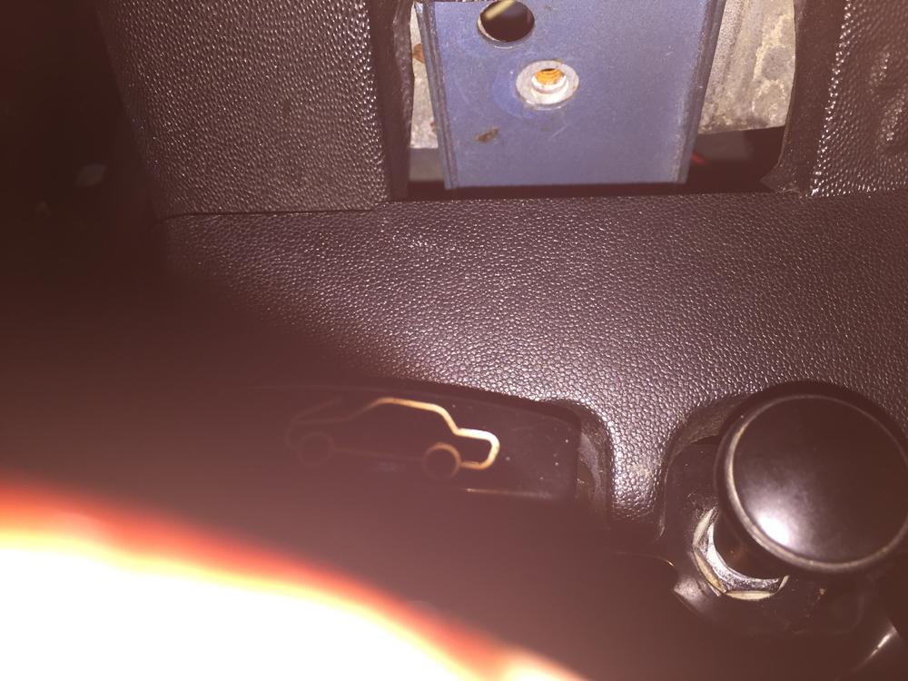
Earlier post re: open space in dash molding on 1977280. Replies did confirm this open area as the place for a dash mounting screw. That being confirmed as the reason for the cutout, I still have doubts about that cutout area not being covered in some way. It looks too obvious/unfinished...even for a series l ?. Wasn’t there some type of plastic cover (molded plastic insert?) to fill space after dash screw installed... press on/pop open cover for access ?? I could paint that area black to reduce contrast of the original body paint color behind dash and visible in this cut out area....I just can’t believe it wasn’t a covered access. Trying not to obsess but it is so obvious with original light blue metal!!! Earlier thread seems to have ended in an accident experiences??. Thank y’all for any pertinent input to this seeming mystery! Please respond to e-mail dbparker54@yahoo.com
-
Need help identify missing part
Thank you for your reply to my posting. I truthfully do not remember this open space originally but I cannot figure out what could have gone there it was over a year before I started this project. I should have taken pictures to refer back to...I never dreamed I wouldn't put this all back together SO much sooner and just put all the nuts, screws and panels/parts in a box marked "interior"? It just seems so odd that this space would have been left open from the factory...but then again, I don't have anything in my "interior box" left over. Still a mystery if it was (what) or never was to begin with and try to ignore... so many mysteries were found , and had to be solved, during this "project". Thank you again for responding!!! Doug
-
Need help identify missing part
Hello! I am Nearing completion of a restoration (final phase is interior renewal/replacement of original finishing panels) for my 1977 280. I need help identifying missing part for space "cut out" . This empty space is above drivers side lower finishing panel (above hood release and vent Knob) and below dash. There is a threaded attaching spot in the middle of this open area on the metal behind dash/panel . My car has factory A/C if that matters? I will try to send picture attachment to clarify mystery space? If it would be better to post this question in another forum, please let me know...I'm trying to access a 280Z (1977?) "resident guru" ? Any help...please e-mail me directly at: dbparker54@yahoo.com. This is the final step in a long (Very Long) restoration so I'd like o solve this mystery and call it done? Thank you for any mystery solution! Doug Parker. PackerZ I will send photo from my I phone in separate post...damn technology ?
-
Steering column shell
I am looking for a steering column cover "clamshell" 1977280Z. Specifically, the lower half panel with all molded mounts intact. Mine has broken mounting "towers" that hold the attaching screws to the upper shell mounts. I have an upper shell with intact mountings. Will consider buying the set if no one has just the lower panel and set is reasonably priced. Please contact me directly at: dbparker54@yahoo.com. Thank you! Doug
-
Dome light wiring
Thank you, again Zed Head. You confirmed my thought that BR really functions as ground wire to/from switch (es)...Black grounds the switch itself and BR sends ground signal to light terminal? Yes I still have to "chisel" door switches out to verify solid ground and probably solve bulb operation during door open-button release. I still have to ask why BR and door switch affects even the manual lens button operation of bulb. Sincerely not to belabor the point, but doesn't the B (constant body ground) terminal make a direct connection with BR terminal and ground side of bulb holder? Even if the BR wire wasn't connected to its terminal... wouldn't the bulb holder's connection with black terminal work for "push button" operation of an installed bulb with constant 12volts at opposite bulb holder/terminal I gotta tell you how gratifying it is for a Club member to respond in a thoughtful and kind manner. It isn't all the time that a fellow Z actually reads the posted question being asked before flaming post response...that is if any (helpful) response to actual question is even given. The difference is noted and appreciated!
-
Dome light wiring
I am trying to understand the wiring functions in the overhead/dome light. I have studied the FSM (Figure BE-23) and the wiring to my light to find out why my light does not work by door contact or manual (lens button). I am trying to use my very basic electrical knowledge and use my voltage tester to determine energized and grounded wires. I clearly test the Blue/white stripe wire as constant 12 volt, battery powered. I also get a functioning ground signal from the black wire. The bulb (even tried several) tests as good. However, I can't get any power across the bulb connections...BW (BE-23 code LW) and Black/red stripe. I know that BR is controlled by door switches, however, my connected, or disconnected, bulb terminal or open/closed doors the BR won't allow power to body ground B allowing bulb to light. Isn't the actual function of the BR wire to create/allow a full grounding at the bulb based on door switch button in/out? To test the door switches, does the BR get any energy to voltage test against B? I see a closed circuit/loop for the BR from the light terminal (with RH and LH split) to each door switch and back with no power to BR...so how would I test each switch? Yes, the LH switch also has a Black and white stripe power and Black ground wires but the switch seems to have two separate circuits for dome light and theft protection and no power shared to BR. Please no flames my confusion but kindly help me to understand switch testing and why BR bulb terminal connection won't close loop allowing LW power to B and allowing light to work manually with door closed. Thank you, for your patience; I'm trying?
-
Ebrake switch
Yippee and way cool? Ya know I would have sworn a black wire was ground... not on a Z anyhow?. Do you possibly have an aftermarket LED bulb part# suggestion/source to match the dimensions of the current (5amp?) dome light bulb. Can an installed bulb be tested by using just the lens push switch if only the Blue w/white stripe (12volt power) and the Black (yeah black=ground this time) are connected to their terminals inside the light housing? or does the Black w/red stripe (from door switches) also have to be connected to its terminal for any bulb to work at all? Last two electrical questions and end of this thread; I swear! You are great, my friend. Thank you.
-
Ebrake switch
Again, thank you! Zed Head, could it be that this black wire, soldered to bottom of the switch, is not a ground wire at all... It might actually be the switch connection to the 12 volt power GY wire. This could explain my male spade black wire and my female plug GY making them the same wire when connected and bringing power to the white plunger button sleeve Then the sleeve is in fact grounded by the switch housing which itself is grounded as part of ebrake assembly bolted to body ground. Do you think maybe I've (finally) got this right? I sure hope so! I really appreciate your excellent feedback and patience with my questions!!! Doug
-
Ebrake switch
Alright! The GY wire does energize the switch and your illustration very clearly shows a factory GY lead out from the switch itself. My switch is missing this outgoing wire ...this would identify what my existing GY wire (coming from C6) with a female plug was once connected to. Thank you for this diagram!!! My '77 FSM didn't show clear detail of switch connection, the yours does! One last question, please: could you direct me to an OEM or aftermarket source for a switch with this GY "pigtail"? Zed Head, Thank you again for your help! Doug
- Ebrake switch
-
Seat panels
Looking for molded plastic panels/covers that cover the S30 first gen Z (280Z) seat hinge assembly. These cover the bolts located on drivers and passenger side hinge assembly for seat back adjustment/rear deck access. They clip on and look like a wide legged cap? They are also found on inner as well as outside-upper two/seat back and lower two for bottom cushion attachment bolts. also looking for: handbrake/parking brake switch (push-in socket with white plunger button and green/yellow stripe spade male lead and black male ground wire.lead from switch. also, black rubber caps that slide over metal rod of seat track adjuster under/front of seat. thank you, Doug. Prefer E contact: dbparker54@yahoo.com
-
Ebrake switch
On my 1977280, the emergency/parking brake switch has only one wire. Black w/ male lead from bottom of switch to ground. The FSM shows this B wire from switch to ground yet also a green/yellow stripe wire going toward the switch..does this GY (ignition powered) energize the switch? How does switch energize for the black wire to function as a ground?
-
Misc 280Z parts
I am looking for a few parts for my 1977 280. Parts needed:. Lower passenger kick panel (cut out for fuse box cover and hides wiring "highway"),. courtesy lamp assembly for overhead console (need mounting tabs intact! ...would like to find two / one for spare-future use backup), fusible link base/block assembly (#1 block/forward/towards battery) mine has broken link terminal☹️...I need a block with metal mounting tab intact and male terminals in good condition. Lastly, if anyone has a good, used aftermarket bracket set for mounting 260 bumpers to 77 280. For reasonable shipping expense, would really prefer if I could purchase items 1-3 together. Please e-mail me at dbparker54@yahoo.com Thank you!!!


