Takhli
Free Member
-
Joined
-
Last visited
-
 You're welcome, son. I've been reviewing your posts and want to compliment you, too, on your brake line installation. Great job there as well. I wish the Mustang was as clean as Dottie; I had to run lines through small passages in the fender wells, between the K-frame and chassis, and against other immovable objects. Having torn out the original lines six years ago didn't help, either. Good thing for the internet and photos I took before disassembly. Dottie is looking really nice.
 -
Considering it's age and the attempts you made to bring it back to original appearance, I think you've done a great job. Looks very nice, and the small imperfections will be hardly noticed, unless you point them out. Good job! 👍
-
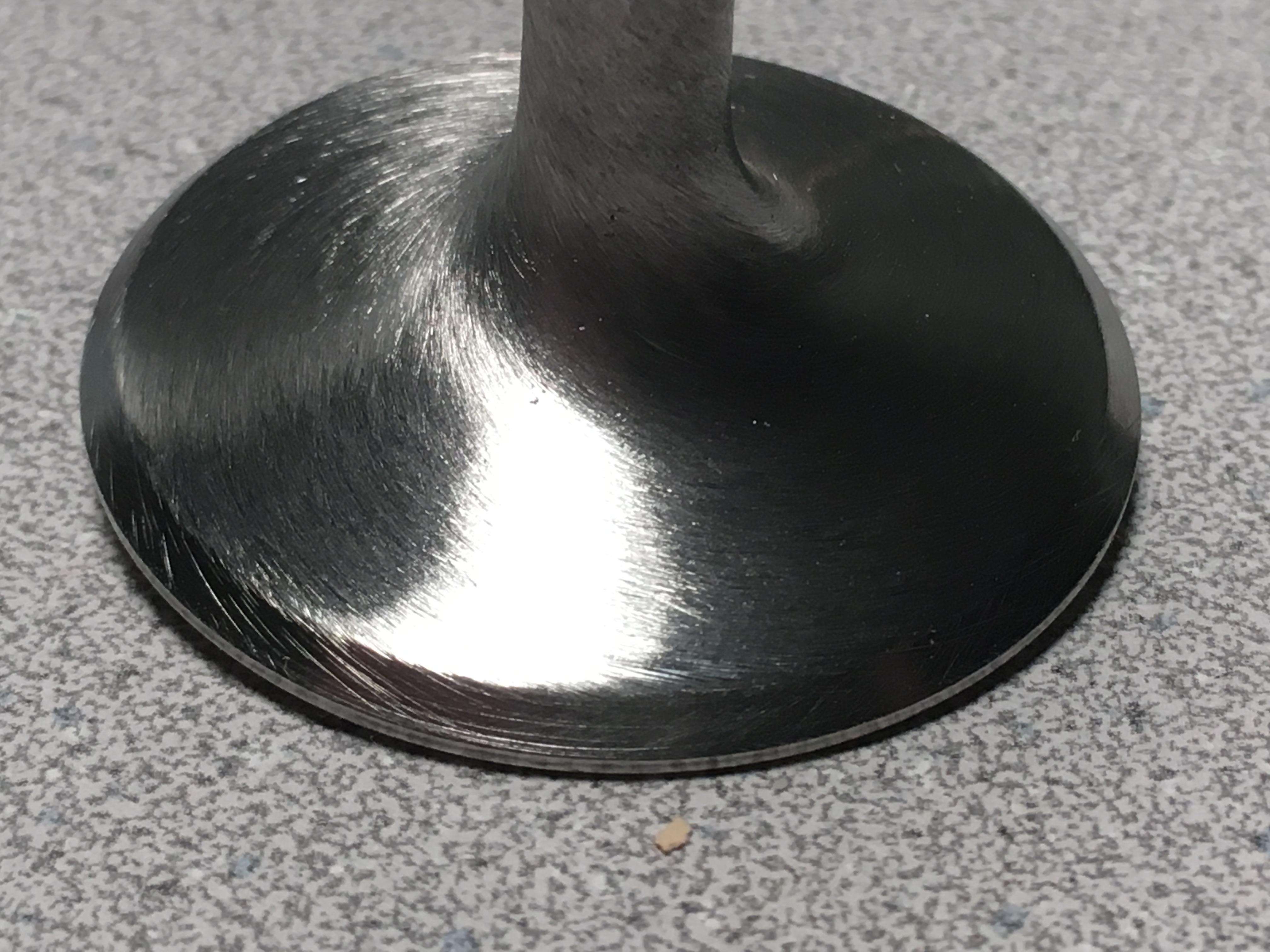
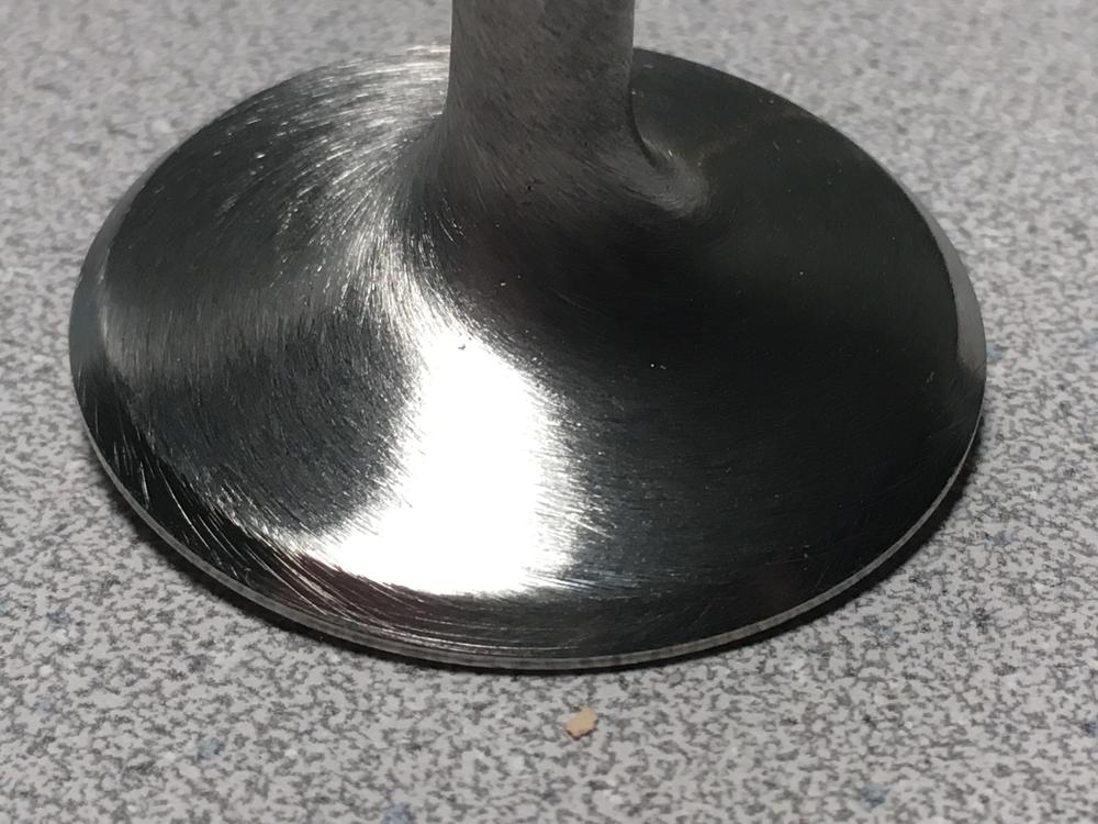
After polishing the face and attempting the swirl pattern the mule weighs 79 grams - a little more than 97.5% of its original weight. After cleaning, but before any polishing and with no appreciable wear on the stems, the Eighteen intake valves we have weighed in at between 81 and 84 grams. But the mule was the only one at 81 grams, where the others were all 82 grams or more. The mule is also the shortest by 0.004-inch so it stood out as the odd ball I could use for experiments. The set of six intakes valve I chose for the engine all weighed 82 grams and had the same length before any polishing, and now weigh 80 grams each. Polishing the combustion face seems to remove about 0.001-inch of material. They have polished combustion faces but no work on the backside. Grinding the faces and dressing the stems will remove more material but I don't know how much. I'm guessing about one gram's worth.
-
With what I've read on swirl polished valves since starting this, I'll agree. One reason I went this far is to learn what kind of results can be accomplished in a home shop. A business wouldn't normally do it and I wouldn't do this for the normal daily driver, but hey.... It's my son's engine, and I have the time. In the Z's hay-day, this kind of work was for engines that lived at the top end - where that last 0.1% is important - and engines were often torn down after a race. Since the car will live on the street, I think we'll just face them with the factory angle and back cut, and call them done. As you mentioned, de-burring and cleaning up the pockets and tracts will do more for performance. They do look pretty, though and we're still happy with the combustion side. Thanks, Captain.
-
You betcha! Beyond polishing, I can't say that there's any measurable benefit with a swirl except that they look pretty and you get bragging rights. They might also be easier to clean next time the head comes off, if ever, but the valves are running a little less than 2 grams lighter after the work is done. Still need to have them refaced but would like honest opinions on the swirl... as if it matters at all. Cheers.


-
Drill press speed was 650 RPM. The 80- and 150-grit were abrasive cloth; everything else was wet-dry with a little WD-40. Have fun; that's what it's all about.
-
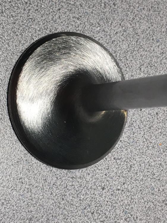
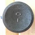
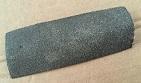
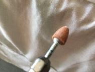
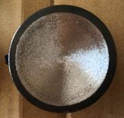
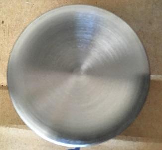
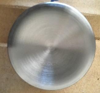
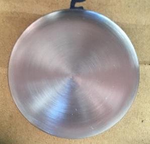
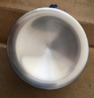
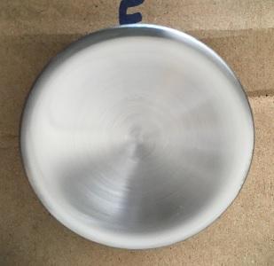
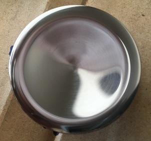
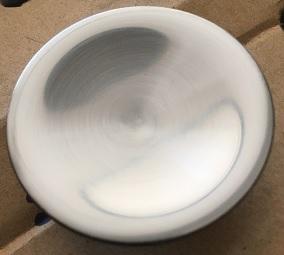
As promised, here are a few photos; they are all the same valve, the test mule. 1. Chuck the valve into a drill, hand tight; spin the valve and break out the Dremel tool 2. Remove only enough metal to clean away the markings 3. 80-grit cloth is next; use it until the grinding marks and casting pits are removed 80-grit surface, below. Don't go crazy near the margin. 4. Follow with 150-grit, 220-grit, etc., until you have the finish you want. I stopped at 600 on the port-side of the head, but took it to 2000 on the face (over kill but it was fun, and only six or seven minutes of polishing). 150 surface below 220 320 400; probably just fine 600 1000 1500 2000


-
It's true... It's a really great exercise for meditation. Matt was interested in some swirl-polished valves when we started, but we're also trying to keep expenses down. I know polishing needed to be done before I could get a swirl pattern, so that's where I started. As far as advantages are concerned; it's something I did on the drone engines I built. With no other mods to ports, testing proved those engines performed better with polished valves. But Matt is also correct in stating its part of a complete package: The bottom end mostly delivers strength and durability, while the top end develops the power. For Matt's engine, the ports will have the valve pockets cleaned and matched, the port entries and exists will match the manifolds (like most folks do), the head will have the stock three-angle valve work but held to tight specifications, and the chambers will be CC'd and polished. The valves are just a part of all that.
-
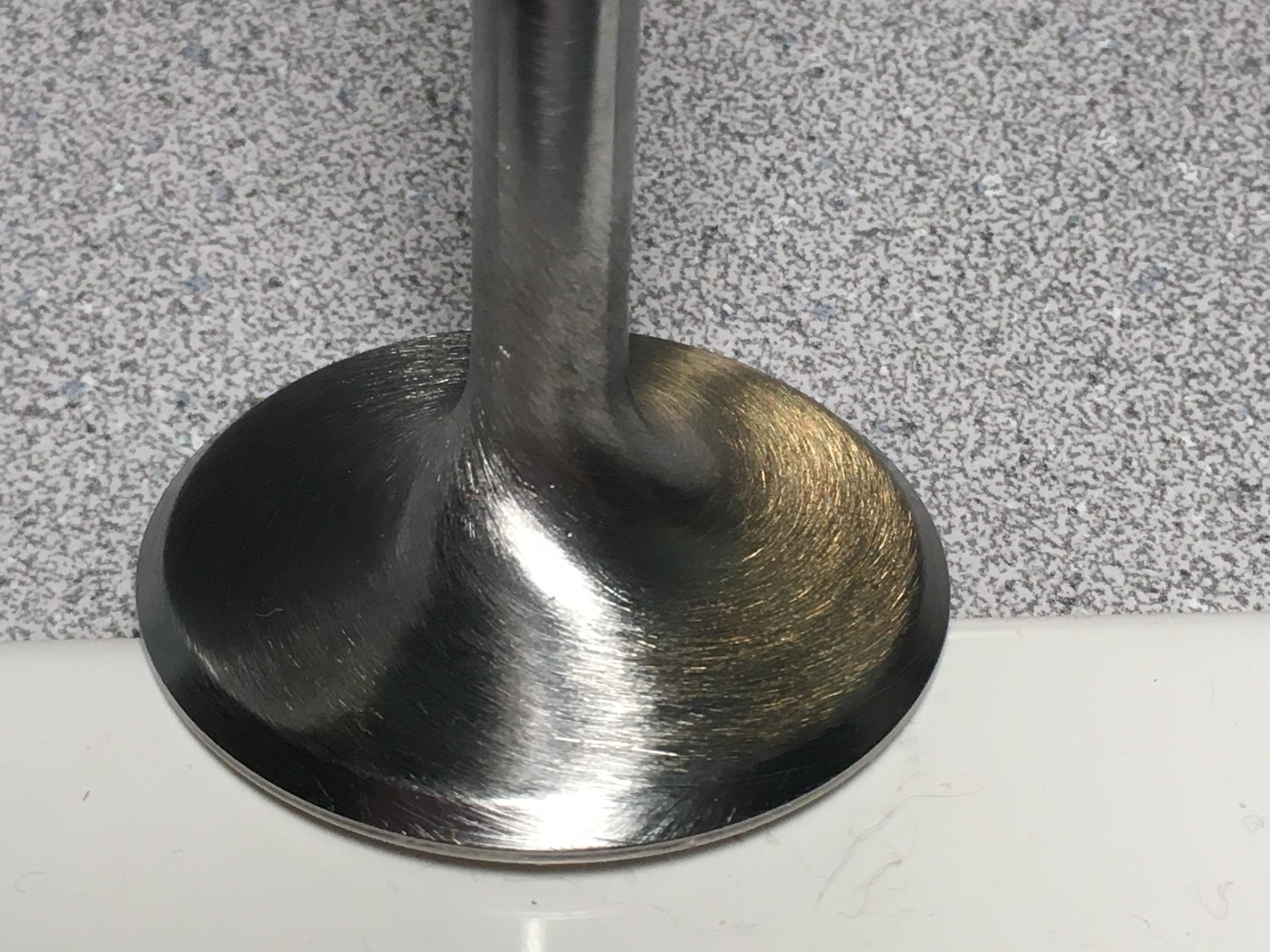
The polished valve Matt posted is the test mule, but I have since completed one full set of intake valves. I started at the drill press, spinning each valve to check for head run-out and wobble. If they checked out (and all of them did) I weighed and measured each one. Eventually, we had two sets of valves fairly consistent in length and weight. We also have a third set but the measurements are not so consistent. The polishing work started on the combustion faces, spinning the valves at about 650 RPM while using a Dremel tool and grinding stone against the direction of rotation, to smooth away the casting marks. Working with a gentle, steady pressure it only took a few minutes to clear the marks from the valve. I followed the grinding with 80-grit abrasive cloth until the grinding stone marks were no longer visible; then moved to successively finer wet-dry papers until I had the finish I wanted. A small bit of WD-40 on the paper helps, and it didn't take more than fifteen-minutes to polish each valve's combustion face. When I was done with one set of six valves I moved to their transition at the valve stem base. Measuring often until the transition blended smoothly, I used a very fine file to carefully turn down the neck of the transition. After this I polished the head and stem transition the same way I did the combustion face, but stopped at the 600-grit finish. Next, I'll re-face each valve with the factory angles, and dress their tips. Admittedly, the mule is way over the top, and 600 grit paper will achieve a very nice finish. Next I plan to experiment to get a swirl pattern on the port-side of the valves, but the combustion chambers are polished so I want the combustion face of the valves polished, as well. More photos to follow, but I'll let Matt do that.
-
Hi, Cap... Initially, I tried to get the inserts as tight as possible but found that with my "lathe" I couldn't be as accurate as I wanted. That said, the sleeves really have a drop-fit into the pivot post well. I'm thinking the clearance varies from 0.002 or so, upto maybe 0.005. Not more. Green Loctite would be what I would use if I had access to a lathe or had the sleeves manufactured by a machine shop. Then, we could have kept the tolerance really tight. Now, though, we are going to use the best epoxy (heat and expansion stable) that we can afford. Maybe that will be good old JB Weld, but I don't think so. I did find some high-quality epoxy by 3M that is very expensive for the amount we will use - I may have mentioned it earlier but can't remember the part number or name. However, I need a really good epoxy to install a few chassis stiffening compontents on my Mustang, so I think I'm going to re-research the stuff and if I find it will hold up to the engine heat, use it for Matt's cylinder head, too. I do know that we want the sleave to fit so that the Time-sert will run freely into the pivot well, matching the threads in the head. The insert can't be run all the way up to the top of the Time-sert because it (the Time-sert) will control that match-up. We can't have a situation where the Time-sert tightens up above the machined face of cylinder head. That in mind, I need to go very easy with whatever epoxy we choose. I know exactly what you mean about the green stuff flashing halfway through an assembly process. I used green locktite to assemble various components during my work on drone engines (really small stuff we manufactured on site). I'm in Tucson and found the stuff is really heat/humidity sensitive, as far a cure is concerned. Work in the coolest dryest environment you can find if you have need of the green stuff again. If you have trouble with it flashing too fast, try the locktite de-bonder; its thinner than the locktite and as long as you catch it fairly quickly, it wicks into the smallest gaps. In the worst cases, we would need to let our parts sit in a bath of de-bonder over night, but we always got them apart. I think I may have used 99.9% pure Iso-propol Alchohol for this purpose as well, but can't recall.
-
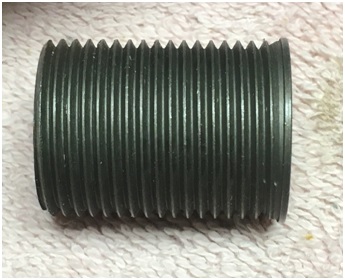
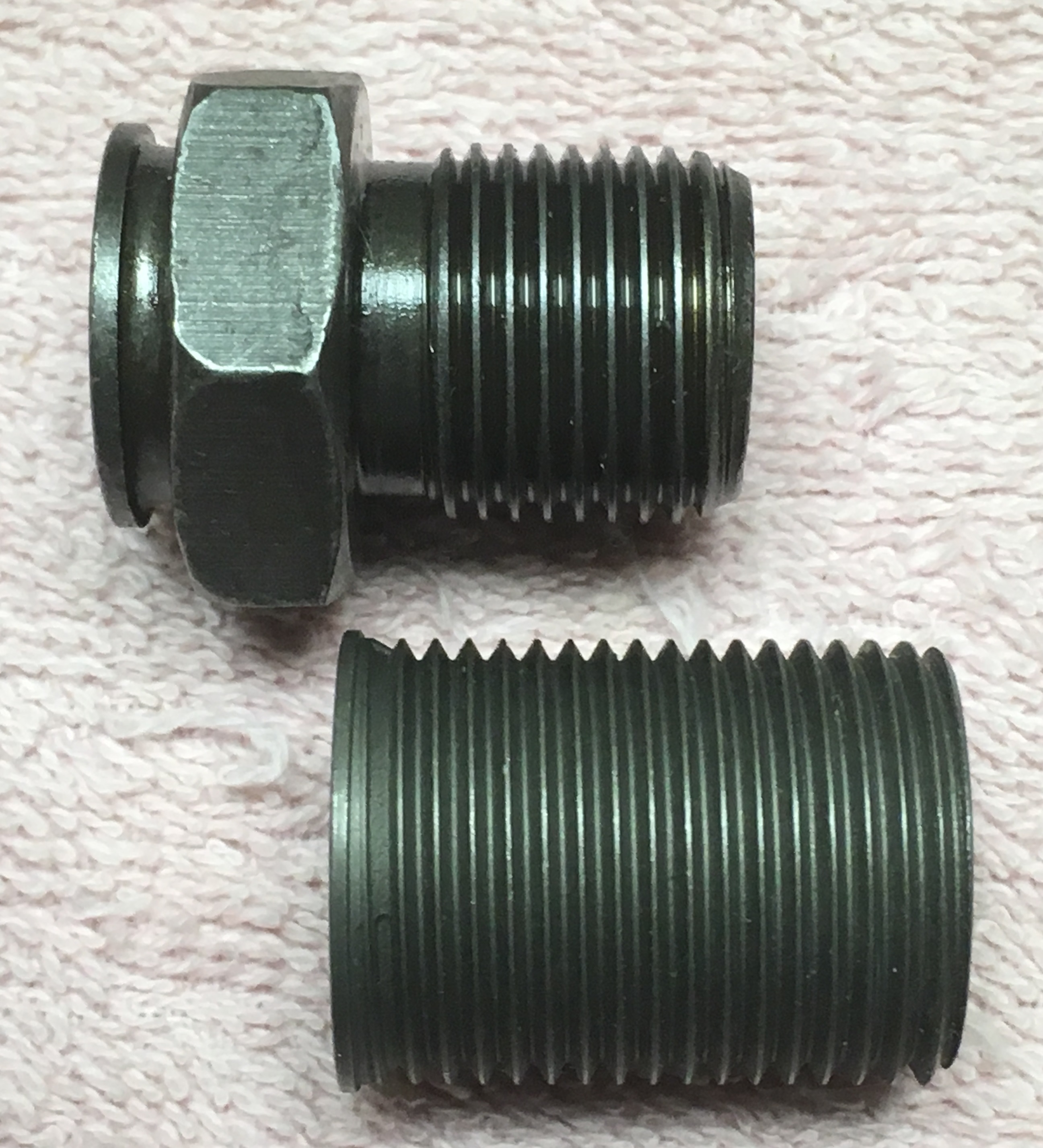
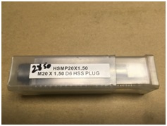
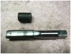
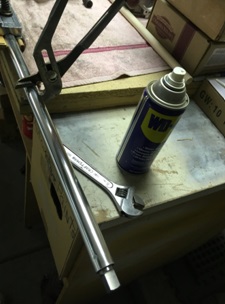
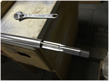
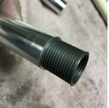
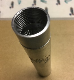
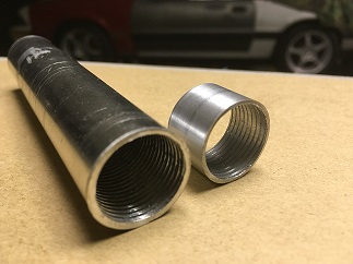
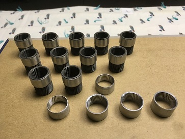
Making Time-sert Sleeves for a P90a - to P90 Rocker Arm Pivot Post Conversion: First, I bought an M22x1.5 tap and a length of 7/8” aluminum tube from the hardware store. An 8-foot length of tubing cost us $32 and the tap cost $28 - much less than labor and materials to have a machine shop make the sleeves. The tap matches the external threads on the Time-sert and the inside diameter of the tube is large enough to accept the tap without drilling it out. The tap won’t cut the full thread depth because the tube’s wall thickness is just slightly too thin; however, that is okay because it makes tapping the tube easier. The reason we need the sleeve is to fill the void between the time-sert and the pivot post well. Sealant and epoxy will make the installation firm so we only need the finished sleeve to thread easily onto the time-sert and fit closely against the pivot post well. “Soft-jaws,’’ used to hold hydraulic fittings, held the aluminum tube in the vise but the tube still slipped when we ran the tap in. Wrapping the tube in 80-grit abrasive cloth provided a better grip but we still had to take small bites with the tap – maybe two or three turns – before backing the tap out to clean things. Cutting oil is an absolute must. Eventually, the tap cuts enough treads to make four or five threaded sleeves, then we cut 6” off the threaded end of the tube and started over. At least three 6"-lengths of tubing are needed for twelve sleeves, and each must be turned to an outside diameter of at least 0.550-inch. Below you can see the diference in diameters, between a partially finished sleeve and the original diameter of the tubing. Its not much. Without a lathe, we used a drill press and homemade spindle setup to do this. I cut the hexagonal head off of an M10x1.75 bolt I found at Ace hardware, cleaned up a damaged lower part of an adjustable pivot, and sacrificed a Time-sert to install over the pivot threads. This made up the drive spindle that fit into my drill press, but we still needed a way to hold and center the opposite end of the tube. I used hard maple to make a tight-fitting plug, fit into the opposite end of the tube. This gave me something relatively soft to bear against a live center (You can find a live center at a wood worker’s supply store; they are used in wood lathes to turn dowels and spindles.) Then, I chucked the live-center vertically into my drill vice and bolted the vice to the drill press to keep the whole setup in line and rigid. With the live-center mounted, and the vice bolted to the frame of the drill press, I could turn down the spinning tube with a coarse file and various grits of sand paper. I took measurments often and when the diameter was right, I cut the tube in pieces approximating the sleeve length. There is a bevel in the P90a pivot post well, near the top of the threads; to match this, each sleeve is given a bevel on its lower outside diameter so it dropps into the pivot post well as far as possible. Also, the inside diameter of the top end was chamfered to let the time-sert thread as far into the sleeve as it could. Total time to make 12 sleeves was 16-hours. Not bad. We will make the installation tool from an M22x1.5 bolt. I'll show that later, when I post the sleeve installation. Hope this helps. Cheers.


-
Very cool. Glad you didn't find any hidden rust. Good work!
-
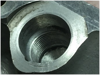
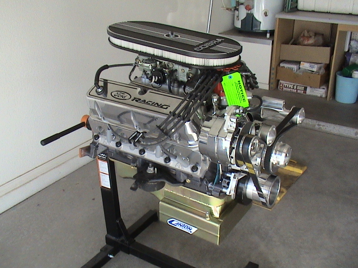
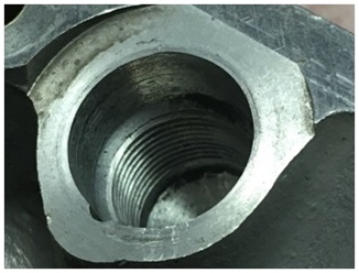
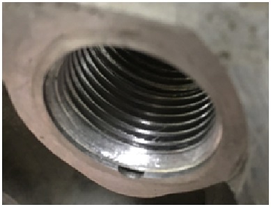
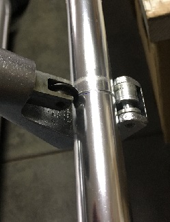
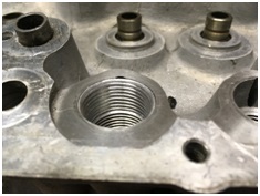
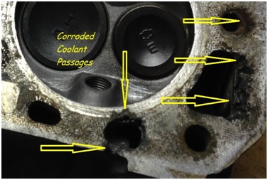
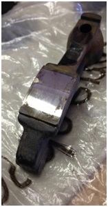
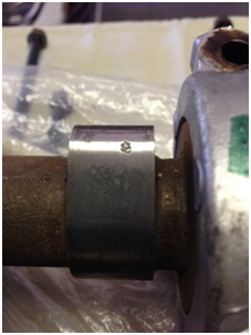
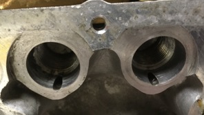
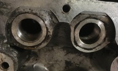
It’s been a while but we're back with more info on the engine buildup. And, since the lower end is pretty much done, we're starting to look at cylinder head reconditioning. Matt may have addressed some of this over time and I questioned the P90a to P90 conversion but bear with us... Matt wants to use either the P90 or P90a Cylinder head because they are said to have better flow and combustion chamber characteristics. He and I looked all over for a head we could use, buying more than one, only to send at least two back to the sellers. I thought a warped head or one that had been surfaced too many times would be the big head ache but the biggest problem turned out to be corrosion. Five heads and two engines later, when our buying frenzy was over, we ended up with one P90 and two P90a heads to choose from. None of the heads were warped but one P90a has been surfaced and needs 0.015 shims under the cam towers; the P90 has some minor issues with intake/exhaust manifold gasket surfaces (minor corrosion); and the second P90a has some pretty bad corrosion around a few coolant passages. All three heads need valve work, including new valve guides but all can be reconditoned. Otherwise, teardown showed that every rocker arm was shot and the hydraulic cams were badly pitted. Matt bought new OEM rocker arms and I sent all three cams to Iskendarian for evaluation. Isky had the cams for about four months and I had to call on their status at least five times. When I finally got hold of Ron Iskendarian he appologized, had the P90 cam polished, and then shipped all three back without charging us a dime. I'd say he did us right. Because the head gasket surface on our second P90a is the truest, and because our machinist tells us he can clean the surface with a 0.003-inch cut after welding up the corrosion, we decided to repair that P90a. But, like almost everyone else rebuilding an engine, we're limited to mechanical cams and need to make the modification that fits the smaller diameter mechanical pivot posts. The mod is well known (except to me, before I started this project), and it's documented on the internet in more than just a few places. But while researching I came up with a few questions, such as: How to control pressurized oil seepage from under the pivot post; supporting the upper part of the Time-serts; and the mileage-life expectancy related to both those questions. The question of oil seepage is easy to fix with short pieces of aluminum dowel in each oil gallery, inside the pivot post bores. The plan is to turn the dowel material to the same outside diameter as the inside diameter of the oil gallery bores; freeze the dowels for an hour or so; warm up the cylinder head to about 120 degrees in momma's oven (I didn't say that) and then tap the cold dowels into each gallery of the warm cylinder head. When temperatures equalize the interference fit should keep everything in place. (When I get to that point, I'll post the photos and narative.) For the same reason that the pivot posts need oil pressure, about ½-inch of depth within the pivot post bore is larger in diameter than the threaded area below. That makes installing threaded inserts easier but leaves most of the insert without mechanical support. Comparing a P90 head with a P90a (below left and right, respectively) there is about 50% less surface area to support a mechanical pivot post if installed in the P90a. Also, using the threaded insert in the P90a only provides about three threads – just 2.25mm or so – where the head material supports both the Time-sert and the mechanical pivot post. Time-serts used to modify the head are about 1/10-inch smaller in outside diameter than the pivot post bore and their installed height must be below the face of the boss. With a higher lift cam, the sweeping action of the cam lobe against the rocker arm is bound to increase lateral forces against the Time-sert. To eliminate the void we need either a machined sleeve around the threaded insert, or something lke an epoxy to fill the gap. Matthew and I decided to use machined aluminum sleeves but the cost would be enormous... ...So,I made about sixteen sleeves in my garage, using not much more than my drill press, my calipers, some files, and sand paper. Here's an installed sleeve in a P90a pivot post bore. Twelve sleeves cost me about $35 in materials and about 18-hours of time (because I didn't have a lathe). Not bad, I think. Method to follow, later. Cheers.
-
Hi, Captain... Matt and I are doing some research on the inserts today, and tomorrow I'll call the maker about the insert's hardness. Maybe it isn't a poblem because, with the pivot post holding the assembly in the hole, the insert sees mostly compression forces rather than shearing forces. But I agree... It seems a bit "hokey". I like your idea of a threaded aluminum sleeve but rather than machining the entire depth of the hole, maybe have it thread onto the pivot and slip into the hole. We could secure the sleeve to the head with green locktight to keep it in place. Still expensive though; I'll need to look around. Also, I think it's interesting that this modification has been around so long and there's hardly any mention of pluging the oil delivery ports. Seems to me that there will be some oil seepage beneath the pivot post if the port isn't plugged.
-
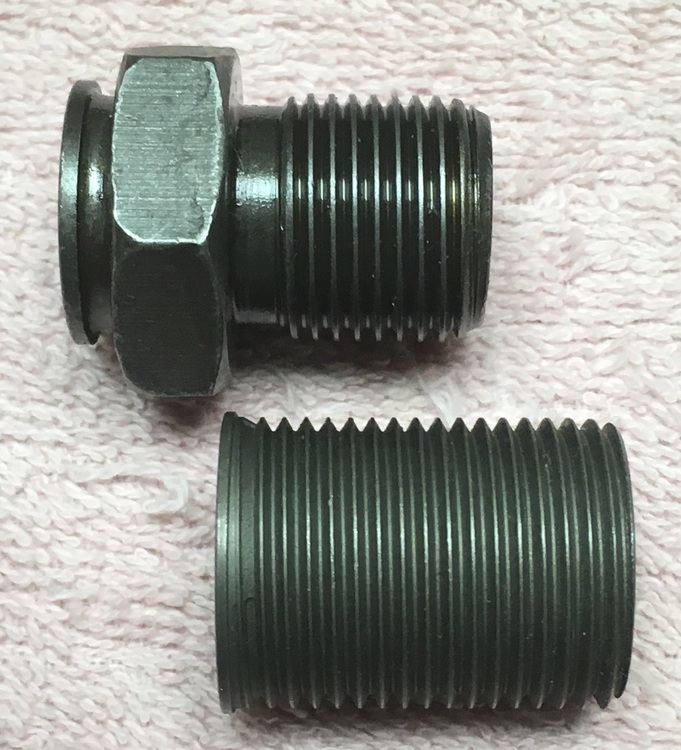
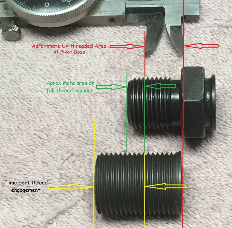
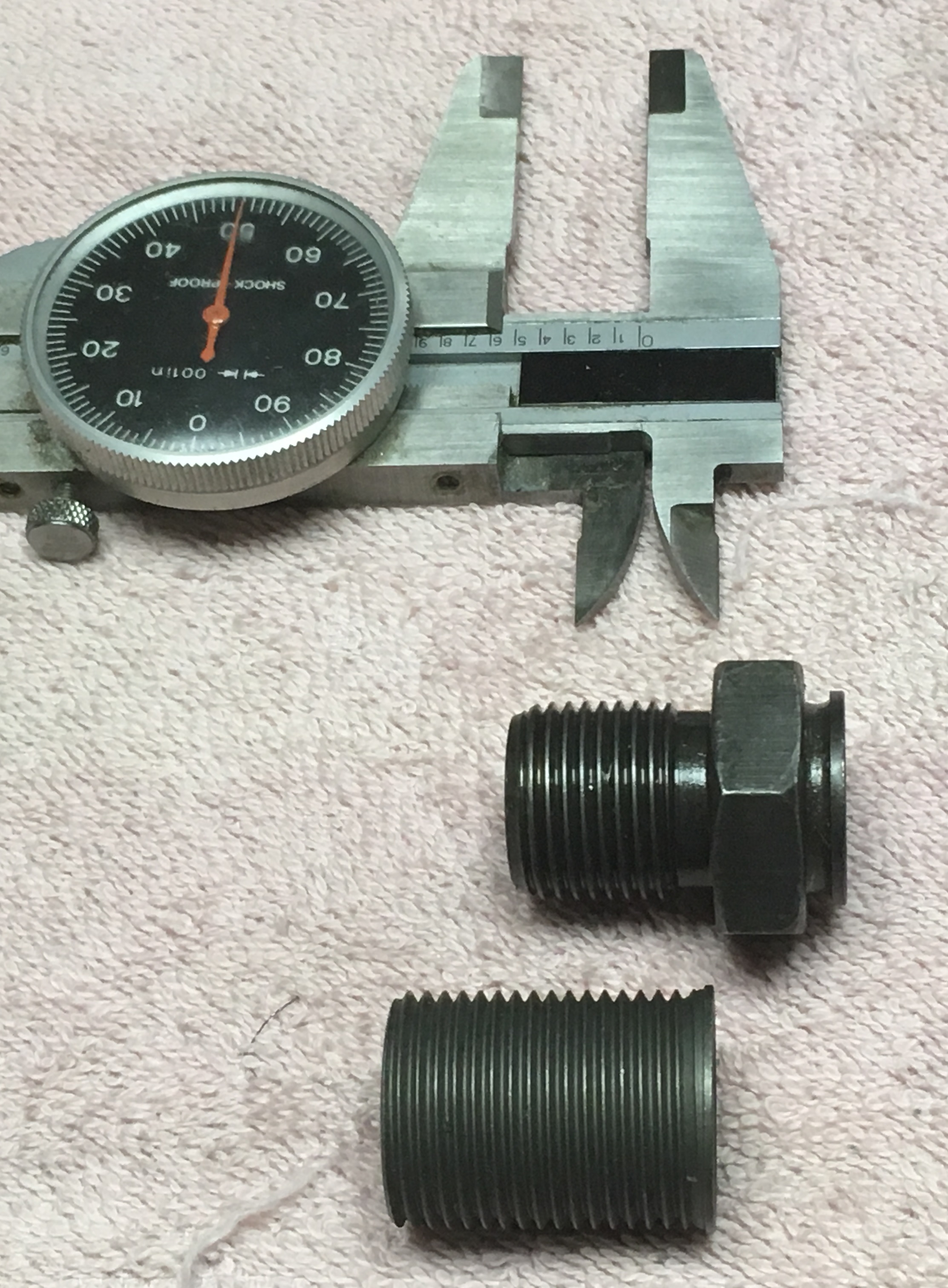
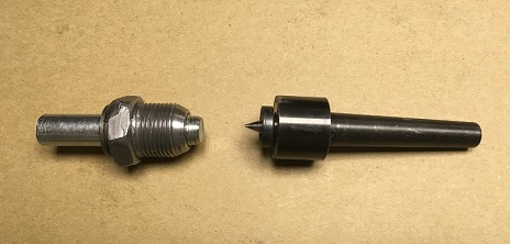
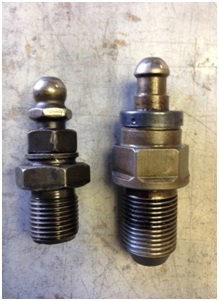
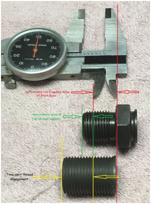
I need to change course a bit here, and ask a question about modifying the P90a for mechanical rocker arm pivots... If anyone knows of another thread on the fourm talking about this, please let me know. Question 1: Is there any known history of Time-sert failure? Reasoning: There are only about three threads of at the base of the rocker arm pivot post where a Time-sert is also supported by cylinder head material. It seems to me that under continuous load - especially with high-lift, longer duration cams requiring heavier valve springs - this is a weak point in the Time-sert, where radial cracking might occur, over time. Correctly installed, the Time-sert is not neccessarily flush with the top of the cylinder head so the installed rocker pivot may or may not provide additional stability. Question 2: Should the unthreaded area between the Time-sert and the cylinder head be filled with an industrial aluminum epoxy filler, to help support the Time-sert? I've included a few photos to help explain. Thoughts on this please... Shown above is the rocker arm pivot post boss on a P90a cylinder head, designed for hydraulic pivot posts, as we know. The unthreaded depth of each boss is aproximately 0.550". Here, above, is the 27mm long 20-1.5 x 18-1.5 Time-sert used to adapt the P90a to solid pivot posts; I believe a shorter insert is also suitable because the hydraulic pivot post does not reach a 27mm depth, as the Time-sert does. In the thread depth comparison above you can see that a mechanical cam pivot post base does not extend to the full depth of the Time-sert,... Here is a measurment comparison of the three components, with the caliper representing the unthreaded depth of the boss.