


Takhli
Free Member
-
Joined
-
Last visited
Everything posted by Takhli
-
 You're welcome, son. I've been reviewing your posts and want to compliment you, too, on your brake line installation. Great job there as well. I wish the Mustang was as clean as Dottie; I had to run lines through small passages in the fender wells, between the K-frame and chassis, and against other immovable objects. Having torn out the original lines six years ago didn't help, either. Good thing for the internet and photos I took before disassembly. Dottie is looking really nice.
 -
Considering it's age and the attempts you made to bring it back to original appearance, I think you've done a great job. Looks very nice, and the small imperfections will be hardly noticed, unless you point them out. Good job! 👍
-
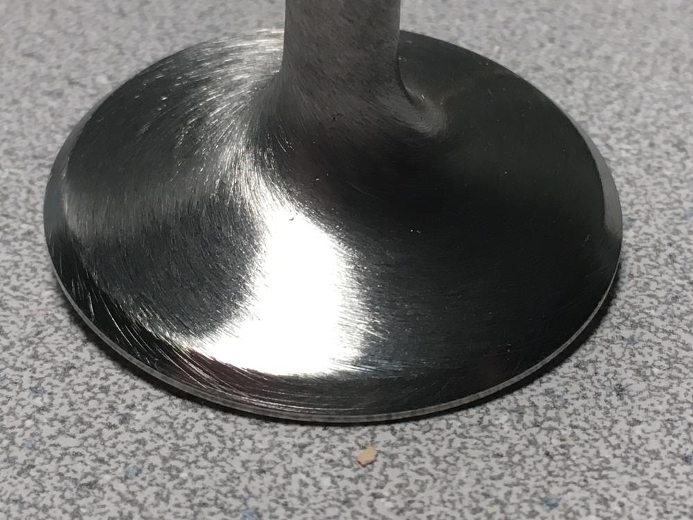
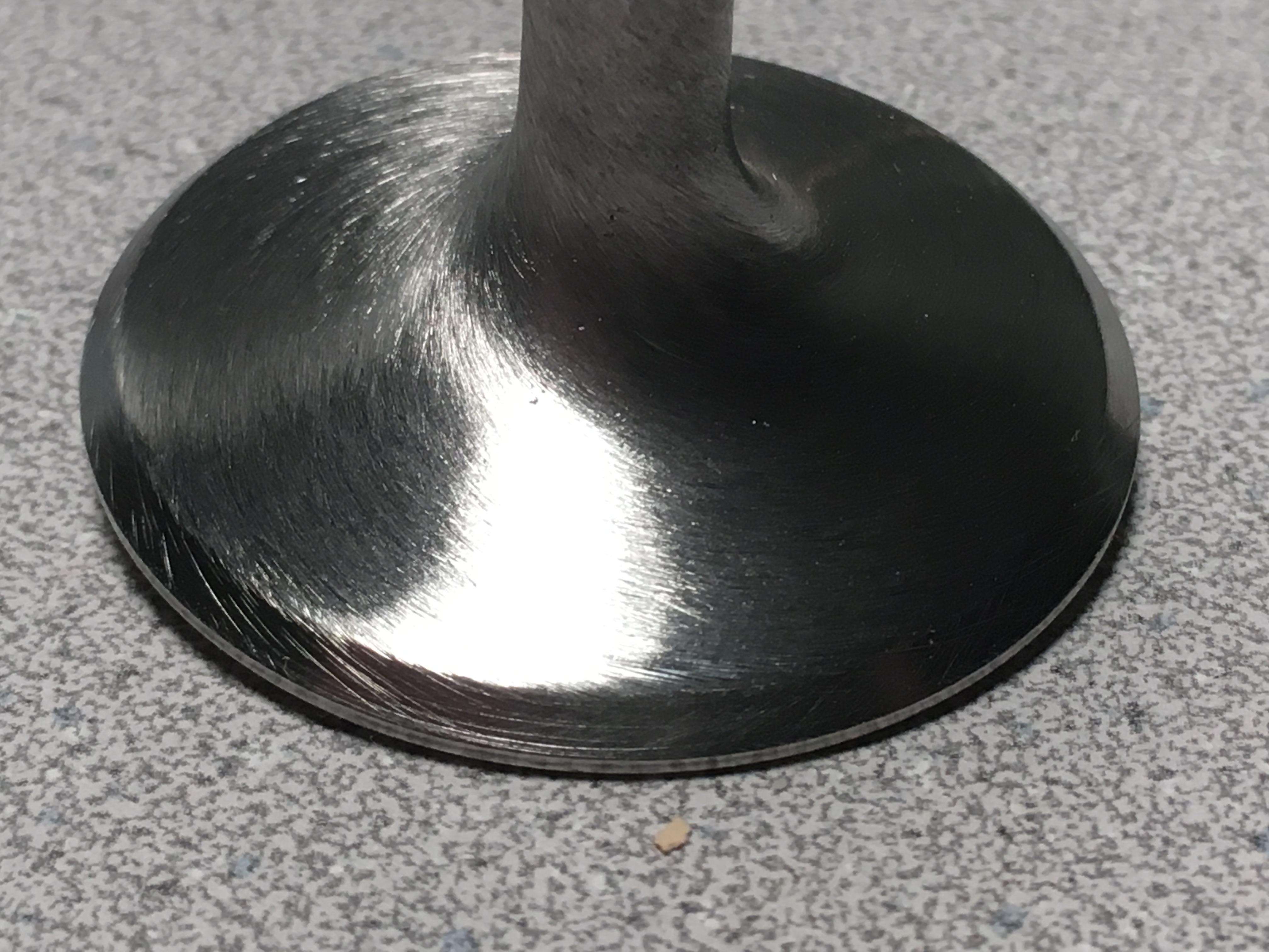
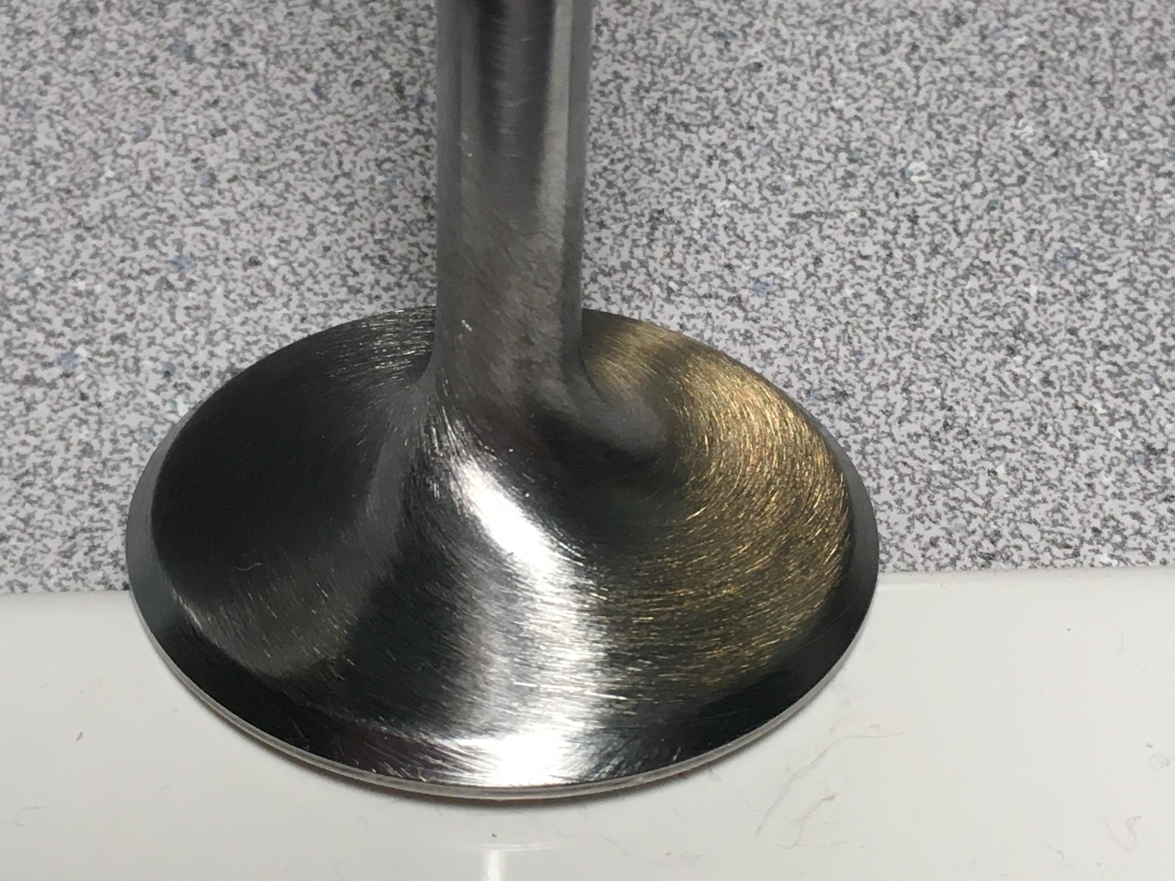
After polishing the face and attempting the swirl pattern the mule weighs 79 grams - a little more than 97.5% of its original weight. After cleaning, but before any polishing and with no appreciable wear on the stems, the Eighteen intake valves we have weighed in at between 81 and 84 grams. But the mule was the only one at 81 grams, where the others were all 82 grams or more. The mule is also the shortest by 0.004-inch so it stood out as the odd ball I could use for experiments. The set of six intakes valve I chose for the engine all weighed 82 grams and had the same length before any polishing, and now weigh 80 grams each. Polishing the combustion face seems to remove about 0.001-inch of material. They have polished combustion faces but no work on the backside. Grinding the faces and dressing the stems will remove more material but I don't know how much. I'm guessing about one gram's worth.
-
With what I've read on swirl polished valves since starting this, I'll agree. One reason I went this far is to learn what kind of results can be accomplished in a home shop. A business wouldn't normally do it and I wouldn't do this for the normal daily driver, but hey.... It's my son's engine, and I have the time. In the Z's hay-day, this kind of work was for engines that lived at the top end - where that last 0.1% is important - and engines were often torn down after a race. Since the car will live on the street, I think we'll just face them with the factory angle and back cut, and call them done. As you mentioned, de-burring and cleaning up the pockets and tracts will do more for performance. They do look pretty, though and we're still happy with the combustion side. Thanks, Captain.
-
You betcha! Beyond polishing, I can't say that there's any measurable benefit with a swirl except that they look pretty and you get bragging rights. They might also be easier to clean next time the head comes off, if ever, but the valves are running a little less than 2 grams lighter after the work is done. Still need to have them refaced but would like honest opinions on the swirl... as if it matters at all. Cheers.


-
Drill press speed was 650 RPM. The 80- and 150-grit were abrasive cloth; everything else was wet-dry with a little WD-40. Have fun; that's what it's all about.
-
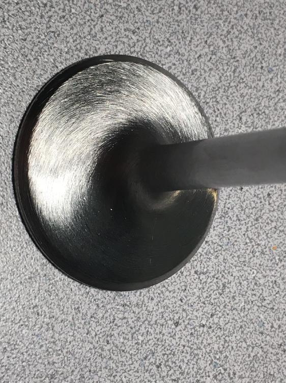
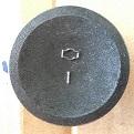
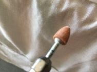
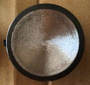
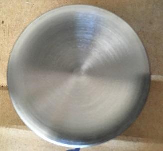
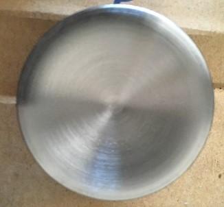
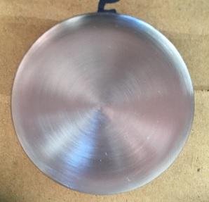
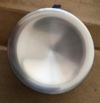
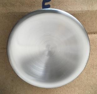
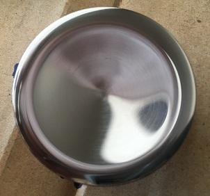
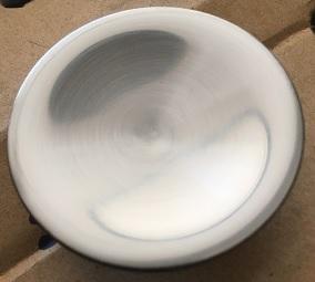
As promised, here are a few photos; they are all the same valve, the test mule. 1. Chuck the valve into a drill, hand tight; spin the valve and break out the Dremel tool 2. Remove only enough metal to clean away the markings 3. 80-grit cloth is next; use it until the grinding marks and casting pits are removed 80-grit surface, below. Don't go crazy near the margin. 4. Follow with 150-grit, 220-grit, etc., until you have the finish you want. I stopped at 600 on the port-side of the head, but took it to 2000 on the face (over kill but it was fun, and only six or seven minutes of polishing). 150 surface below 220 320 400; probably just fine 600 1000 1500 2000


-
It's true... It's a really great exercise for meditation. Matt was interested in some swirl-polished valves when we started, but we're also trying to keep expenses down. I know polishing needed to be done before I could get a swirl pattern, so that's where I started. As far as advantages are concerned; it's something I did on the drone engines I built. With no other mods to ports, testing proved those engines performed better with polished valves. But Matt is also correct in stating its part of a complete package: The bottom end mostly delivers strength and durability, while the top end develops the power. For Matt's engine, the ports will have the valve pockets cleaned and matched, the port entries and exists will match the manifolds (like most folks do), the head will have the stock three-angle valve work but held to tight specifications, and the chambers will be CC'd and polished. The valves are just a part of all that.
-
The polished valve Matt posted is the test mule, but I have since completed one full set of intake valves. I started at the drill press, spinning each valve to check for head run-out and wobble. If they checked out (and all of them did) I weighed and measured each one. Eventually, we had two sets of valves fairly consistent in length and weight. We also have a third set but the measurements are not so consistent. The polishing work started on the combustion faces, spinning the valves at about 650 RPM while using a Dremel tool and grinding stone against the direction of rotation, to smooth away the casting marks. Working with a gentle, steady pressure it only took a few minutes to clear the marks from the valve. I followed the grinding with 80-grit abrasive cloth until the grinding stone marks were no longer visible; then moved to successively finer wet-dry papers until I had the finish I wanted. A small bit of WD-40 on the paper helps, and it didn't take more than fifteen-minutes to polish each valve's combustion face. When I was done with one set of six valves I moved to their transition at the valve stem base. Measuring often until the transition blended smoothly, I used a very fine file to carefully turn down the neck of the transition. After this I polished the head and stem transition the same way I did the combustion face, but stopped at the 600-grit finish. Next, I'll re-face each valve with the factory angles, and dress their tips. Admittedly, the mule is way over the top, and 600 grit paper will achieve a very nice finish. Next I plan to experiment to get a swirl pattern on the port-side of the valves, but the combustion chambers are polished so I want the combustion face of the valves polished, as well. More photos to follow, but I'll let Matt do that.
-
Hi, Cap... Initially, I tried to get the inserts as tight as possible but found that with my "lathe" I couldn't be as accurate as I wanted. That said, the sleeves really have a drop-fit into the pivot post well. I'm thinking the clearance varies from 0.002 or so, upto maybe 0.005. Not more. Green Loctite would be what I would use if I had access to a lathe or had the sleeves manufactured by a machine shop. Then, we could have kept the tolerance really tight. Now, though, we are going to use the best epoxy (heat and expansion stable) that we can afford. Maybe that will be good old JB Weld, but I don't think so. I did find some high-quality epoxy by 3M that is very expensive for the amount we will use - I may have mentioned it earlier but can't remember the part number or name. However, I need a really good epoxy to install a few chassis stiffening compontents on my Mustang, so I think I'm going to re-research the stuff and if I find it will hold up to the engine heat, use it for Matt's cylinder head, too. I do know that we want the sleave to fit so that the Time-sert will run freely into the pivot well, matching the threads in the head. The insert can't be run all the way up to the top of the Time-sert because it (the Time-sert) will control that match-up. We can't have a situation where the Time-sert tightens up above the machined face of cylinder head. That in mind, I need to go very easy with whatever epoxy we choose. I know exactly what you mean about the green stuff flashing halfway through an assembly process. I used green locktite to assemble various components during my work on drone engines (really small stuff we manufactured on site). I'm in Tucson and found the stuff is really heat/humidity sensitive, as far a cure is concerned. Work in the coolest dryest environment you can find if you have need of the green stuff again. If you have trouble with it flashing too fast, try the locktite de-bonder; its thinner than the locktite and as long as you catch it fairly quickly, it wicks into the smallest gaps. In the worst cases, we would need to let our parts sit in a bath of de-bonder over night, but we always got them apart. I think I may have used 99.9% pure Iso-propol Alchohol for this purpose as well, but can't recall.
-
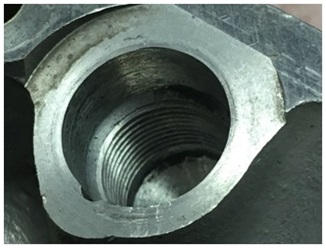
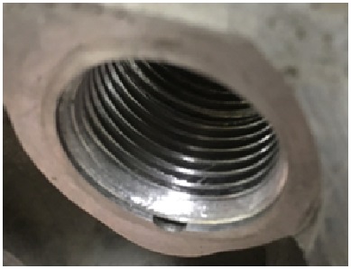
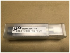
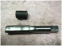
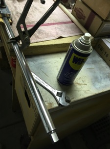
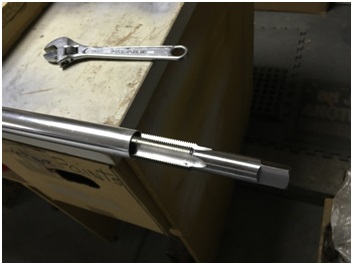
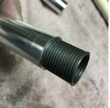
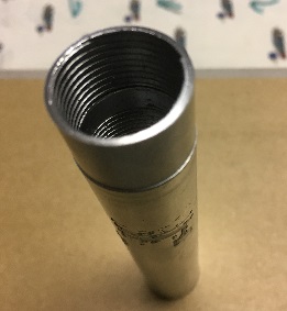
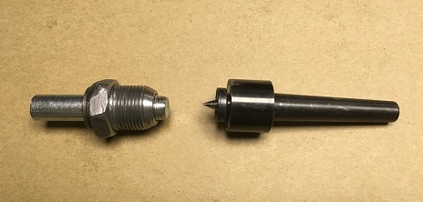
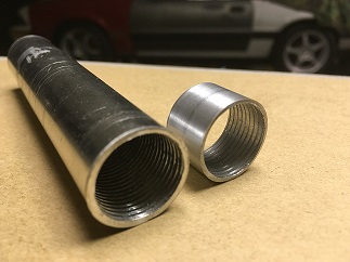
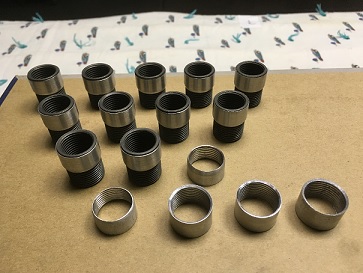
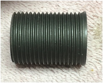
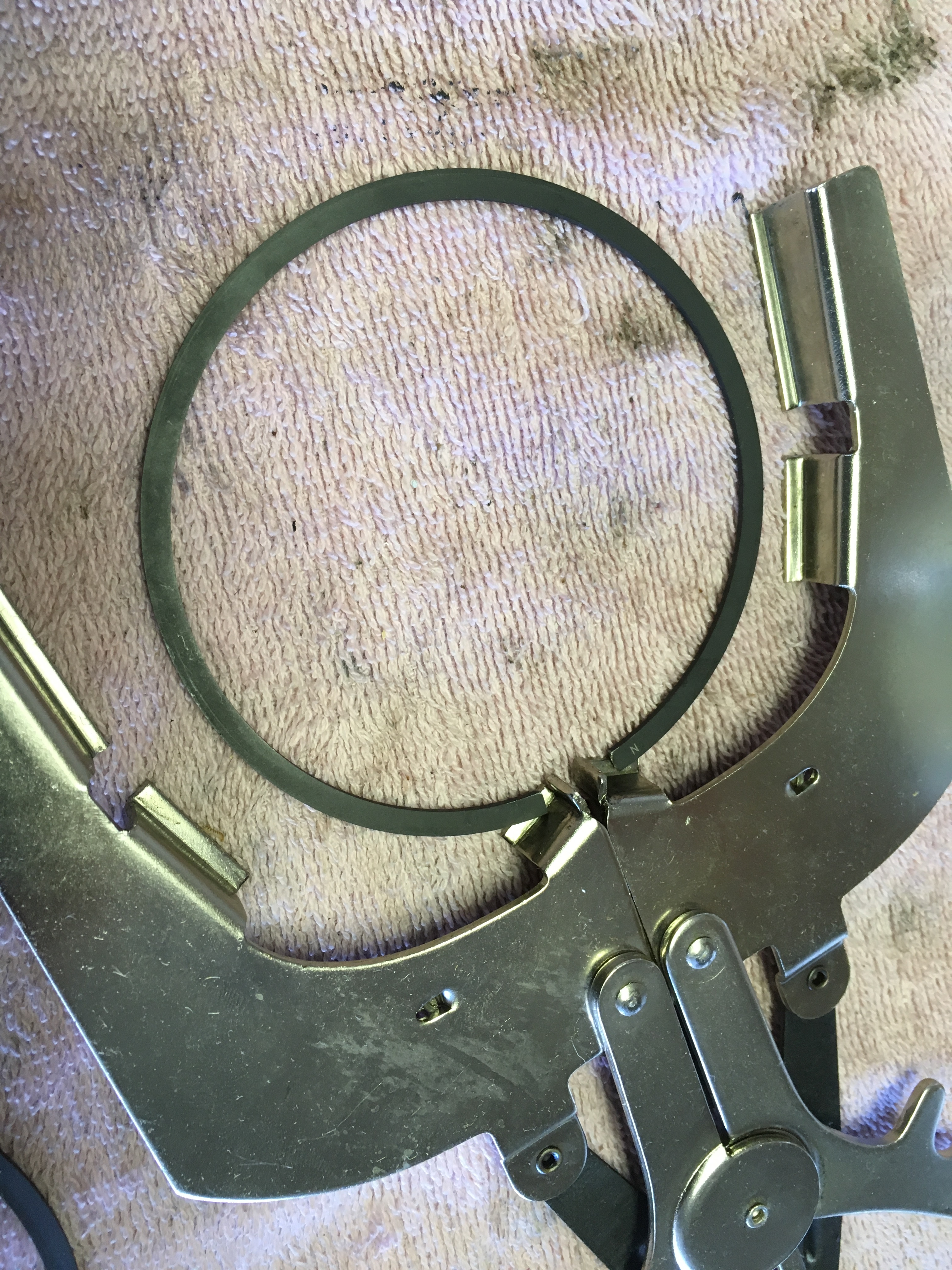
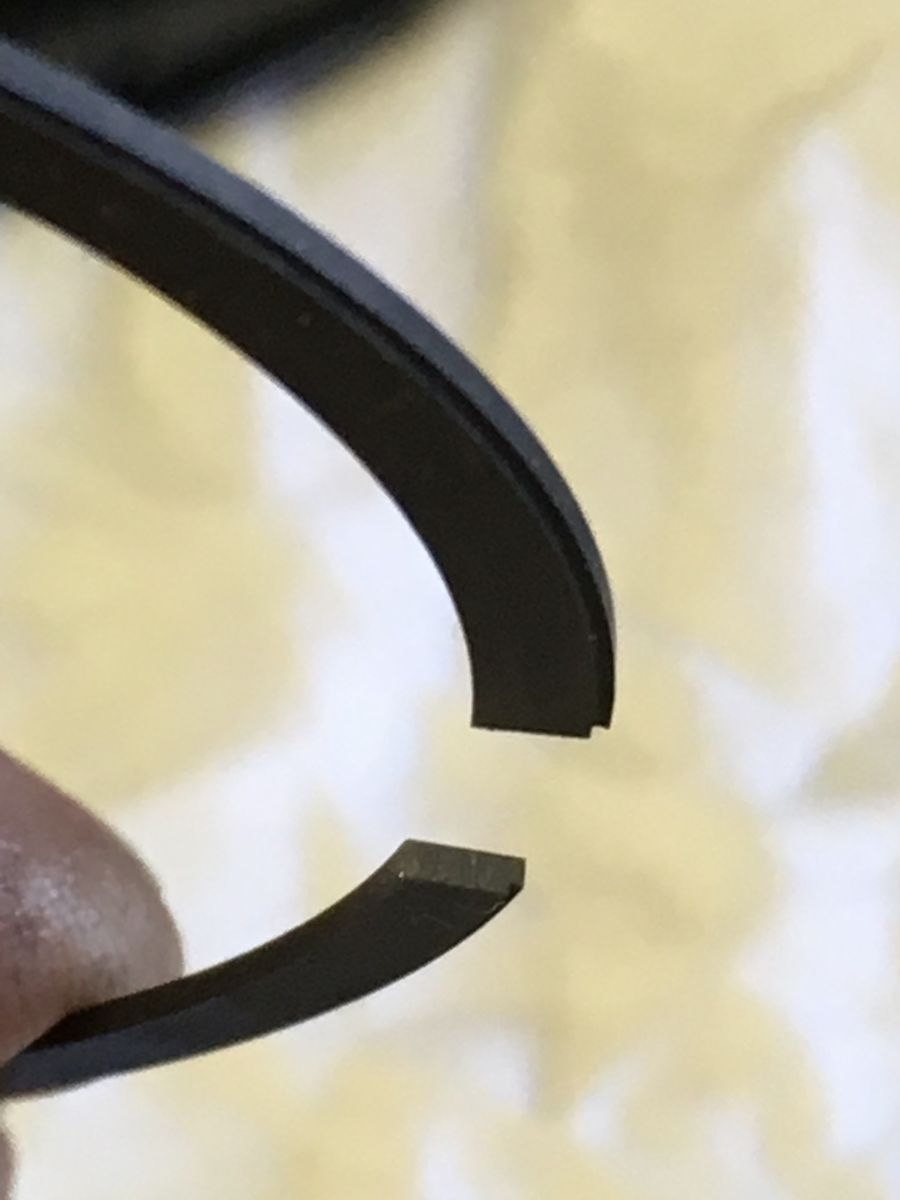
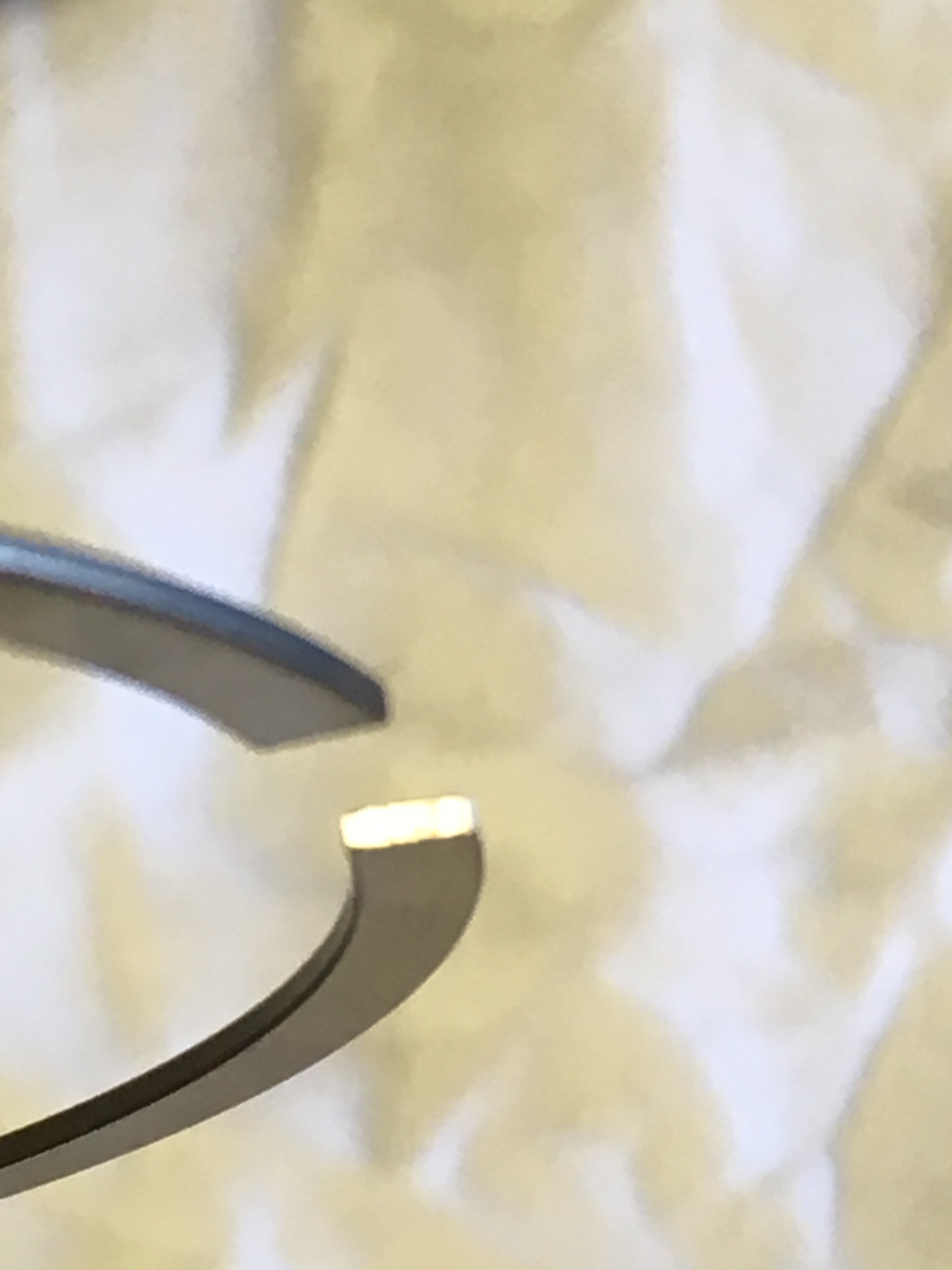
Making Time-sert Sleeves for a P90a - to P90 Rocker Arm Pivot Post Conversion: First, I bought an M22x1.5 tap and a length of 7/8” aluminum tube from the hardware store. An 8-foot length of tubing cost us $32 and the tap cost $28 - much less than labor and materials to have a machine shop make the sleeves. The tap matches the external threads on the Time-sert and the inside diameter of the tube is large enough to accept the tap without drilling it out. The tap won’t cut the full thread depth because the tube’s wall thickness is just slightly too thin; however, that is okay because it makes tapping the tube easier. The reason we need the sleeve is to fill the void between the time-sert and the pivot post well. Sealant and epoxy will make the installation firm so we only need the finished sleeve to thread easily onto the time-sert and fit closely against the pivot post well. “Soft-jaws,’’ used to hold hydraulic fittings, held the aluminum tube in the vise but the tube still slipped when we ran the tap in. Wrapping the tube in 80-grit abrasive cloth provided a better grip but we still had to take small bites with the tap – maybe two or three turns – before backing the tap out to clean things. Cutting oil is an absolute must. Eventually, the tap cuts enough treads to make four or five threaded sleeves, then we cut 6” off the threaded end of the tube and started over. At least three 6"-lengths of tubing are needed for twelve sleeves, and each must be turned to an outside diameter of at least 0.550-inch. Below you can see the diference in diameters, between a partially finished sleeve and the original diameter of the tubing. Its not much. Without a lathe, we used a drill press and homemade spindle setup to do this. I cut the hexagonal head off of an M10x1.75 bolt I found at Ace hardware, cleaned up a damaged lower part of an adjustable pivot, and sacrificed a Time-sert to install over the pivot threads. This made up the drive spindle that fit into my drill press, but we still needed a way to hold and center the opposite end of the tube. I used hard maple to make a tight-fitting plug, fit into the opposite end of the tube. This gave me something relatively soft to bear against a live center (You can find a live center at a wood worker’s supply store; they are used in wood lathes to turn dowels and spindles.) Then, I chucked the live-center vertically into my drill vice and bolted the vice to the drill press to keep the whole setup in line and rigid. With the live-center mounted, and the vice bolted to the frame of the drill press, I could turn down the spinning tube with a coarse file and various grits of sand paper. I took measurments often and when the diameter was right, I cut the tube in pieces approximating the sleeve length. There is a bevel in the P90a pivot post well, near the top of the threads; to match this, each sleeve is given a bevel on its lower outside diameter so it dropps into the pivot post well as far as possible. Also, the inside diameter of the top end was chamfered to let the time-sert thread as far into the sleeve as it could. Total time to make 12 sleeves was 16-hours. Not bad. We will make the installation tool from an M22x1.5 bolt. I'll show that later, when I post the sleeve installation. Hope this helps. Cheers.


-
Very cool. Glad you didn't find any hidden rust. Good work!
-
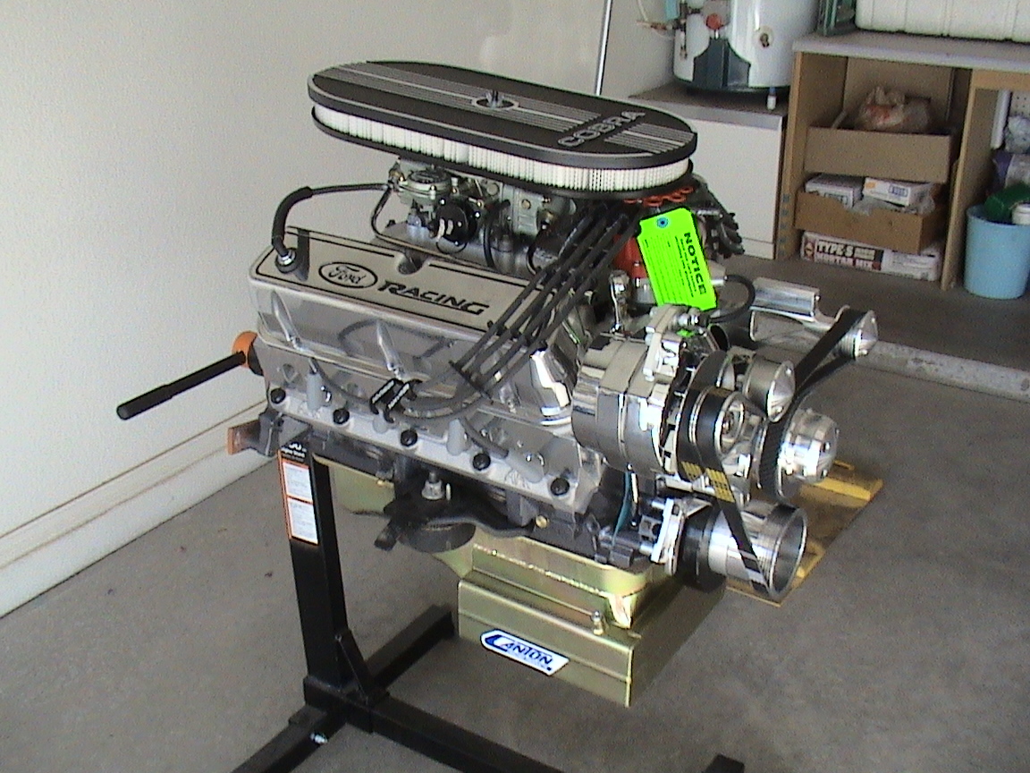
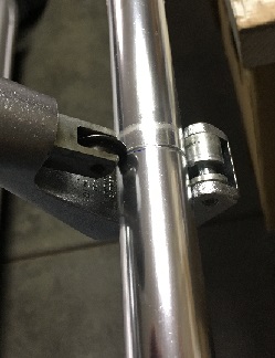
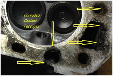
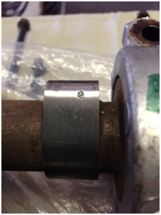
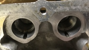
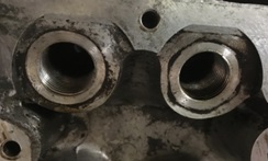
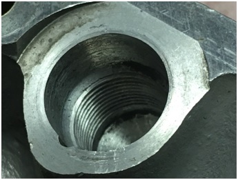
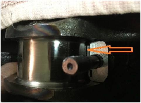
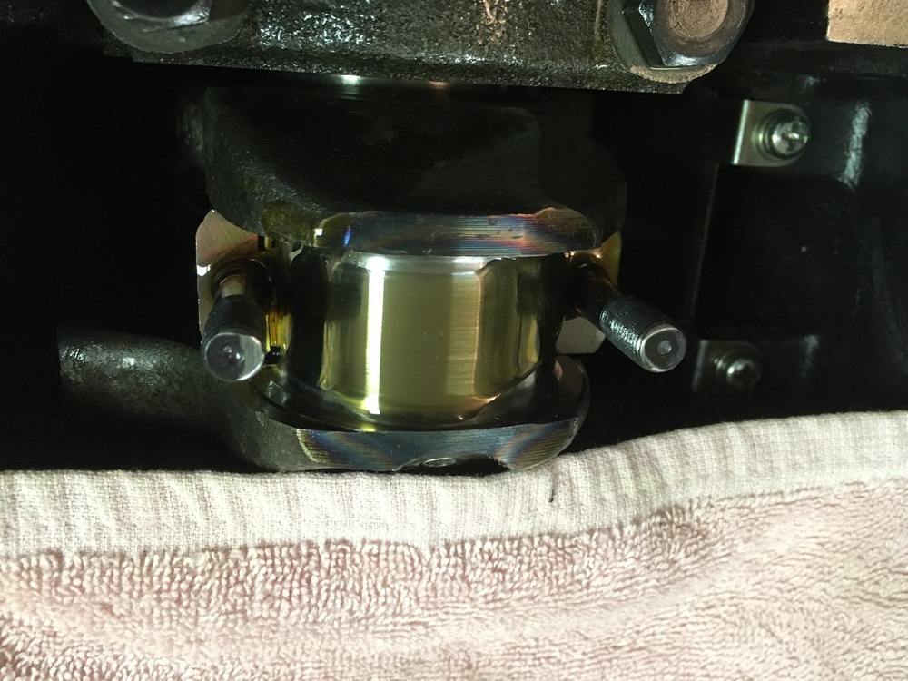
It’s been a while but we're back with more info on the engine buildup. And, since the lower end is pretty much done, we're starting to look at cylinder head reconditioning. Matt may have addressed some of this over time and I questioned the P90a to P90 conversion but bear with us... Matt wants to use either the P90 or P90a Cylinder head because they are said to have better flow and combustion chamber characteristics. He and I looked all over for a head we could use, buying more than one, only to send at least two back to the sellers. I thought a warped head or one that had been surfaced too many times would be the big head ache but the biggest problem turned out to be corrosion. Five heads and two engines later, when our buying frenzy was over, we ended up with one P90 and two P90a heads to choose from. None of the heads were warped but one P90a has been surfaced and needs 0.015 shims under the cam towers; the P90 has some minor issues with intake/exhaust manifold gasket surfaces (minor corrosion); and the second P90a has some pretty bad corrosion around a few coolant passages. All three heads need valve work, including new valve guides but all can be reconditoned. Otherwise, teardown showed that every rocker arm was shot and the hydraulic cams were badly pitted. Matt bought new OEM rocker arms and I sent all three cams to Iskendarian for evaluation. Isky had the cams for about four months and I had to call on their status at least five times. When I finally got hold of Ron Iskendarian he appologized, had the P90 cam polished, and then shipped all three back without charging us a dime. I'd say he did us right. Because the head gasket surface on our second P90a is the truest, and because our machinist tells us he can clean the surface with a 0.003-inch cut after welding up the corrosion, we decided to repair that P90a. But, like almost everyone else rebuilding an engine, we're limited to mechanical cams and need to make the modification that fits the smaller diameter mechanical pivot posts. The mod is well known (except to me, before I started this project), and it's documented on the internet in more than just a few places. But while researching I came up with a few questions, such as: How to control pressurized oil seepage from under the pivot post; supporting the upper part of the Time-serts; and the mileage-life expectancy related to both those questions. The question of oil seepage is easy to fix with short pieces of aluminum dowel in each oil gallery, inside the pivot post bores. The plan is to turn the dowel material to the same outside diameter as the inside diameter of the oil gallery bores; freeze the dowels for an hour or so; warm up the cylinder head to about 120 degrees in momma's oven (I didn't say that) and then tap the cold dowels into each gallery of the warm cylinder head. When temperatures equalize the interference fit should keep everything in place. (When I get to that point, I'll post the photos and narative.) For the same reason that the pivot posts need oil pressure, about ½-inch of depth within the pivot post bore is larger in diameter than the threaded area below. That makes installing threaded inserts easier but leaves most of the insert without mechanical support. Comparing a P90 head with a P90a (below left and right, respectively) there is about 50% less surface area to support a mechanical pivot post if installed in the P90a. Also, using the threaded insert in the P90a only provides about three threads – just 2.25mm or so – where the head material supports both the Time-sert and the mechanical pivot post. Time-serts used to modify the head are about 1/10-inch smaller in outside diameter than the pivot post bore and their installed height must be below the face of the boss. With a higher lift cam, the sweeping action of the cam lobe against the rocker arm is bound to increase lateral forces against the Time-sert. To eliminate the void we need either a machined sleeve around the threaded insert, or something lke an epoxy to fill the gap. Matthew and I decided to use machined aluminum sleeves but the cost would be enormous... ...So,I made about sixteen sleeves in my garage, using not much more than my drill press, my calipers, some files, and sand paper. Here's an installed sleeve in a P90a pivot post bore. Twelve sleeves cost me about $35 in materials and about 18-hours of time (because I didn't have a lathe). Not bad, I think. Method to follow, later. Cheers.
-
Hi, Captain... Matt and I are doing some research on the inserts today, and tomorrow I'll call the maker about the insert's hardness. Maybe it isn't a poblem because, with the pivot post holding the assembly in the hole, the insert sees mostly compression forces rather than shearing forces. But I agree... It seems a bit "hokey". I like your idea of a threaded aluminum sleeve but rather than machining the entire depth of the hole, maybe have it thread onto the pivot and slip into the hole. We could secure the sleeve to the head with green locktight to keep it in place. Still expensive though; I'll need to look around. Also, I think it's interesting that this modification has been around so long and there's hardly any mention of pluging the oil delivery ports. Seems to me that there will be some oil seepage beneath the pivot post if the port isn't plugged.
-
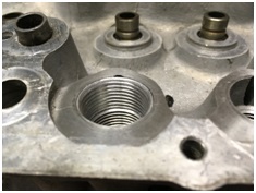
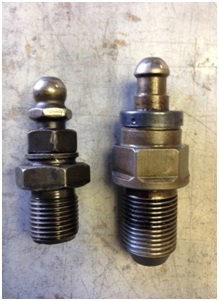
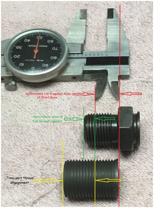
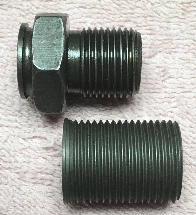
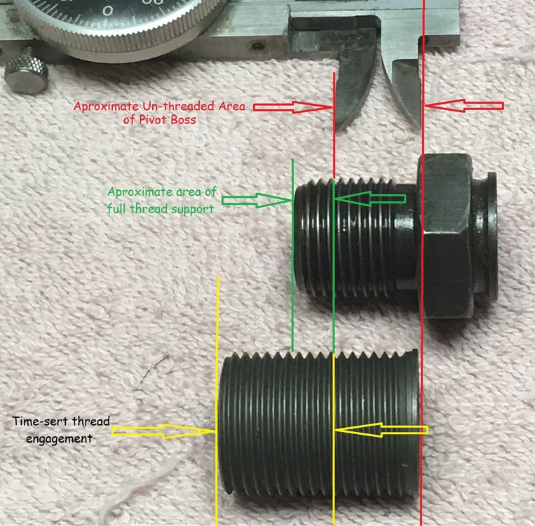
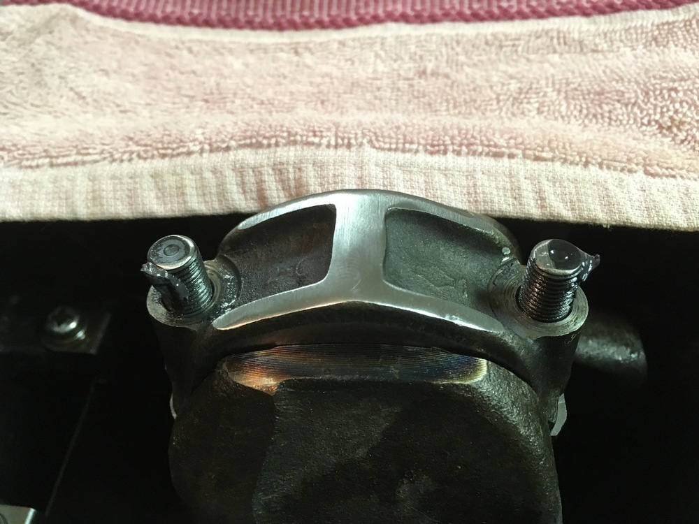
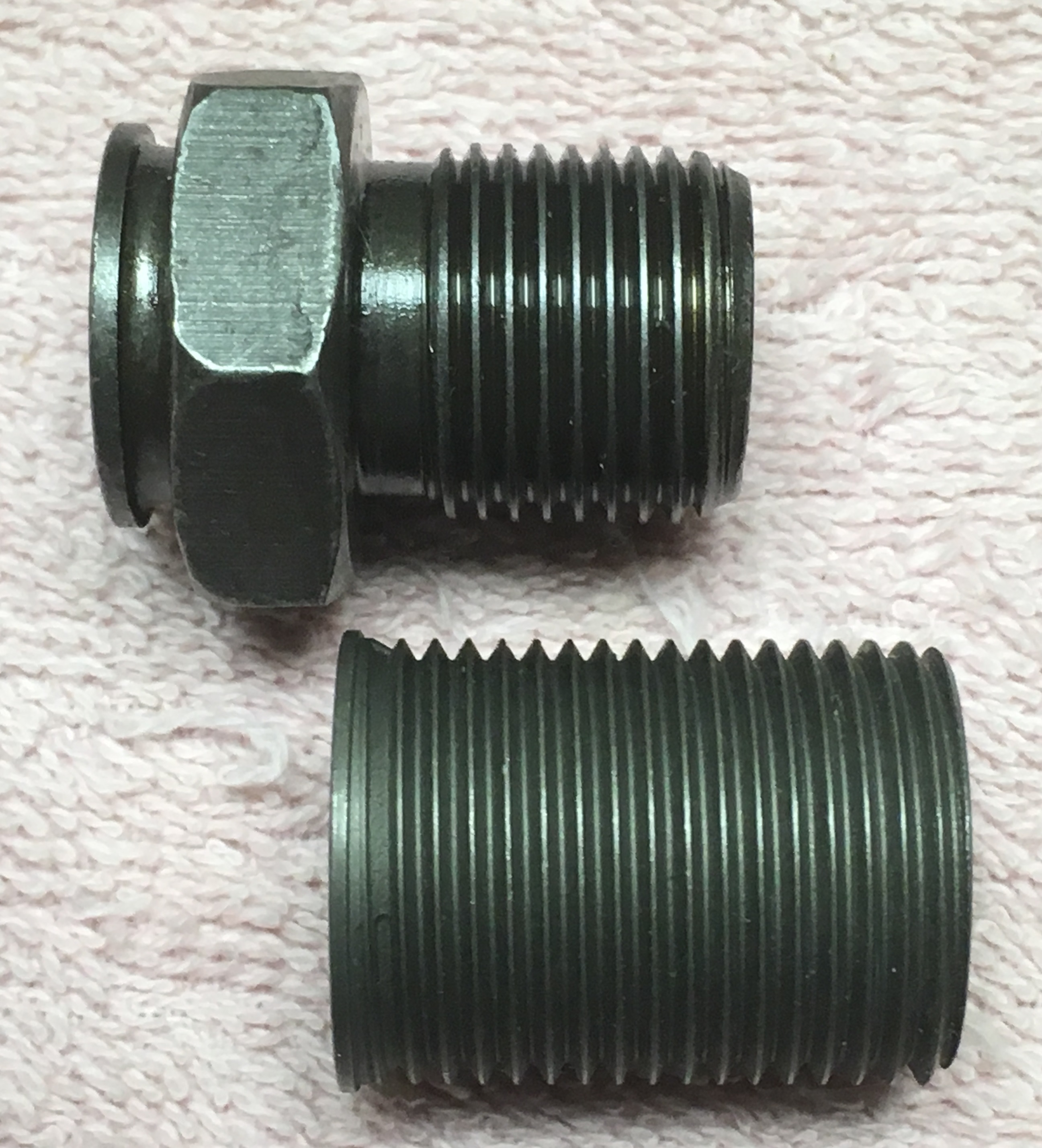
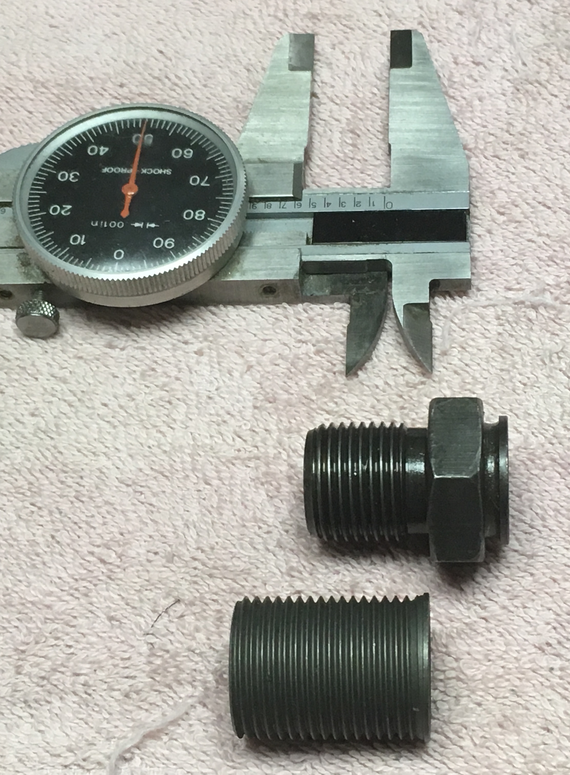
I need to change course a bit here, and ask a question about modifying the P90a for mechanical rocker arm pivots... If anyone knows of another thread on the fourm talking about this, please let me know. Question 1: Is there any known history of Time-sert failure? Reasoning: There are only about three threads of at the base of the rocker arm pivot post where a Time-sert is also supported by cylinder head material. It seems to me that under continuous load - especially with high-lift, longer duration cams requiring heavier valve springs - this is a weak point in the Time-sert, where radial cracking might occur, over time. Correctly installed, the Time-sert is not neccessarily flush with the top of the cylinder head so the installed rocker pivot may or may not provide additional stability. Question 2: Should the unthreaded area between the Time-sert and the cylinder head be filled with an industrial aluminum epoxy filler, to help support the Time-sert? I've included a few photos to help explain. Thoughts on this please... Shown above is the rocker arm pivot post boss on a P90a cylinder head, designed for hydraulic pivot posts, as we know. The unthreaded depth of each boss is aproximately 0.550". Here, above, is the 27mm long 20-1.5 x 18-1.5 Time-sert used to adapt the P90a to solid pivot posts; I believe a shorter insert is also suitable because the hydraulic pivot post does not reach a 27mm depth, as the Time-sert does. In the thread depth comparison above you can see that a mechanical cam pivot post base does not extend to the full depth of the Time-sert,... Here is a measurment comparison of the three components, with the caliper representing the unthreaded depth of the boss.

-
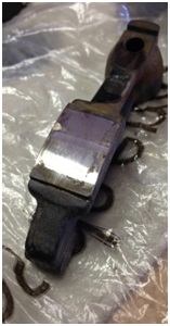
Good point, Captain. If I recall correctly, number 5 locked up after about 45-degrees rotation and was free when I turned it back past BDC, for some period. And although number 6 was similar it never really "locked up"; it just became very, very tight, until I decided it was too much. As far as swapping the rods into other cylinders - no, that didn't happen. However, I did try swapping the bearing inserts but it didn't help much. I could turn 5 a little more but it still locked up. By the time I finished trying number 6 installed and torqued it was late and I figured that I should make the next decission after a night's sleep. In the morning I decided to run the tow assemblies into the machinist for inspection. Glad you mentioned it though; that was a good reminder.
-
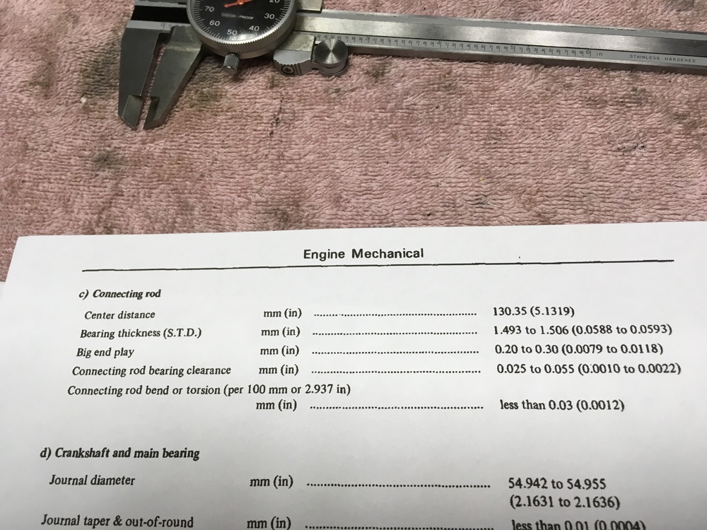
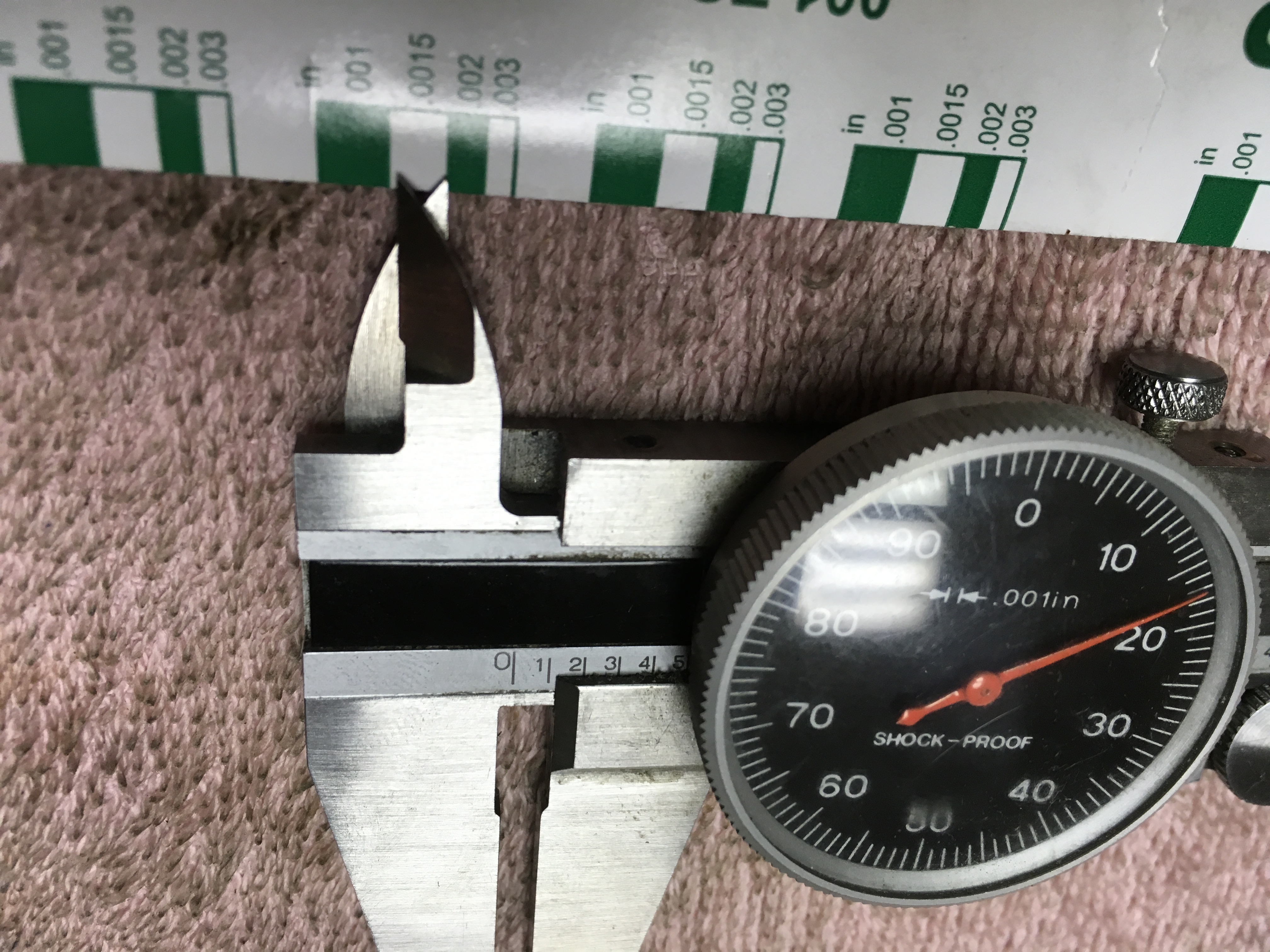
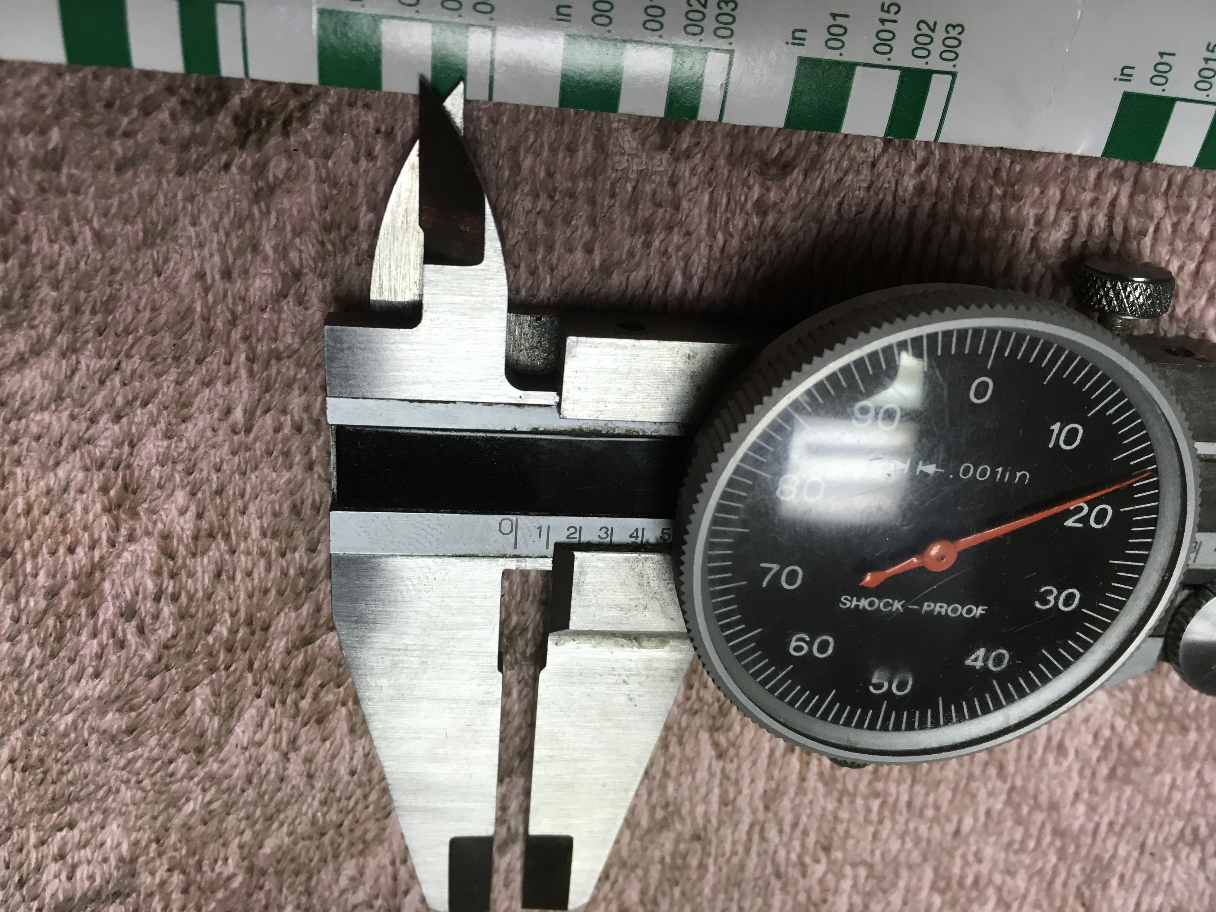
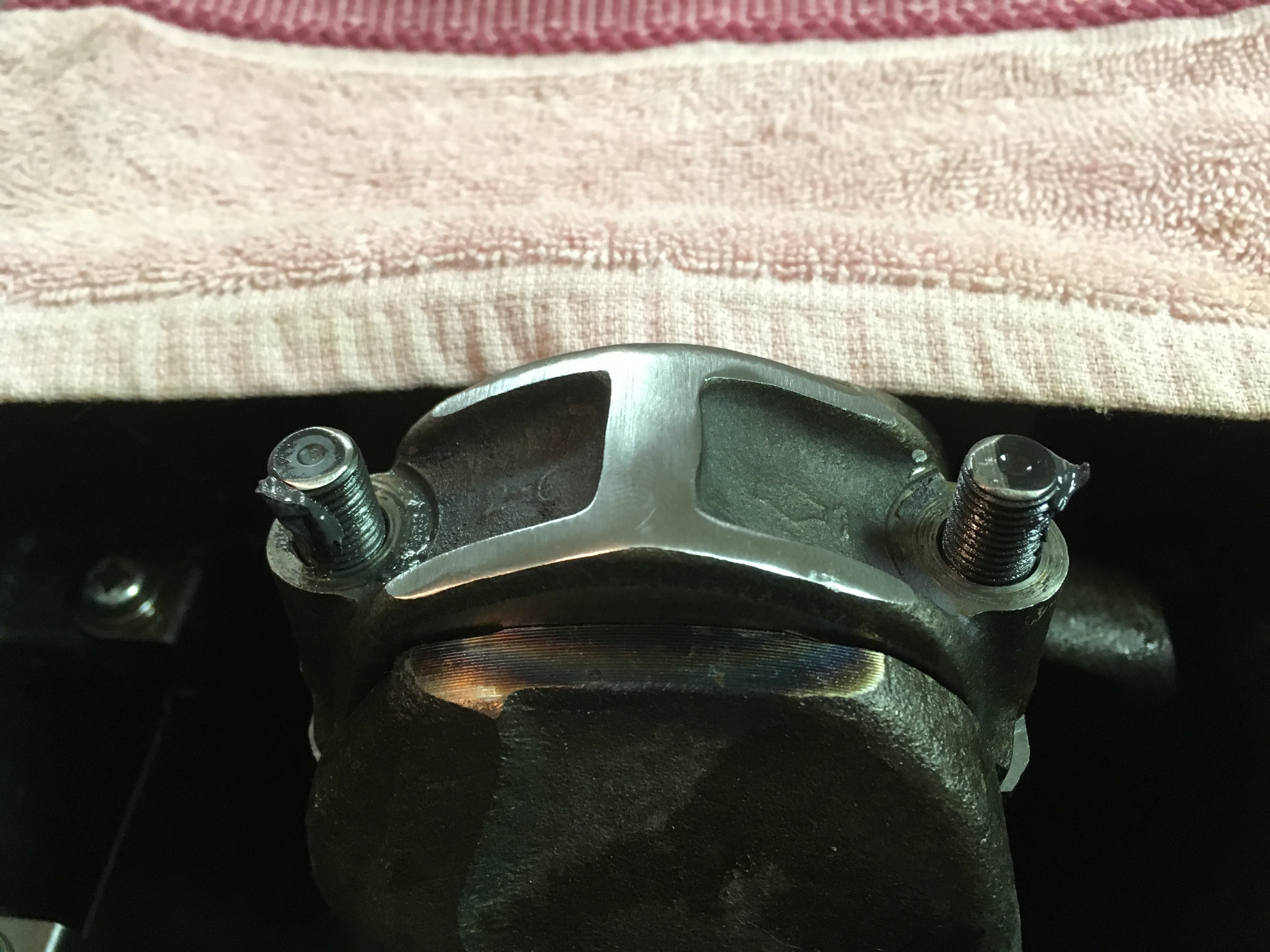
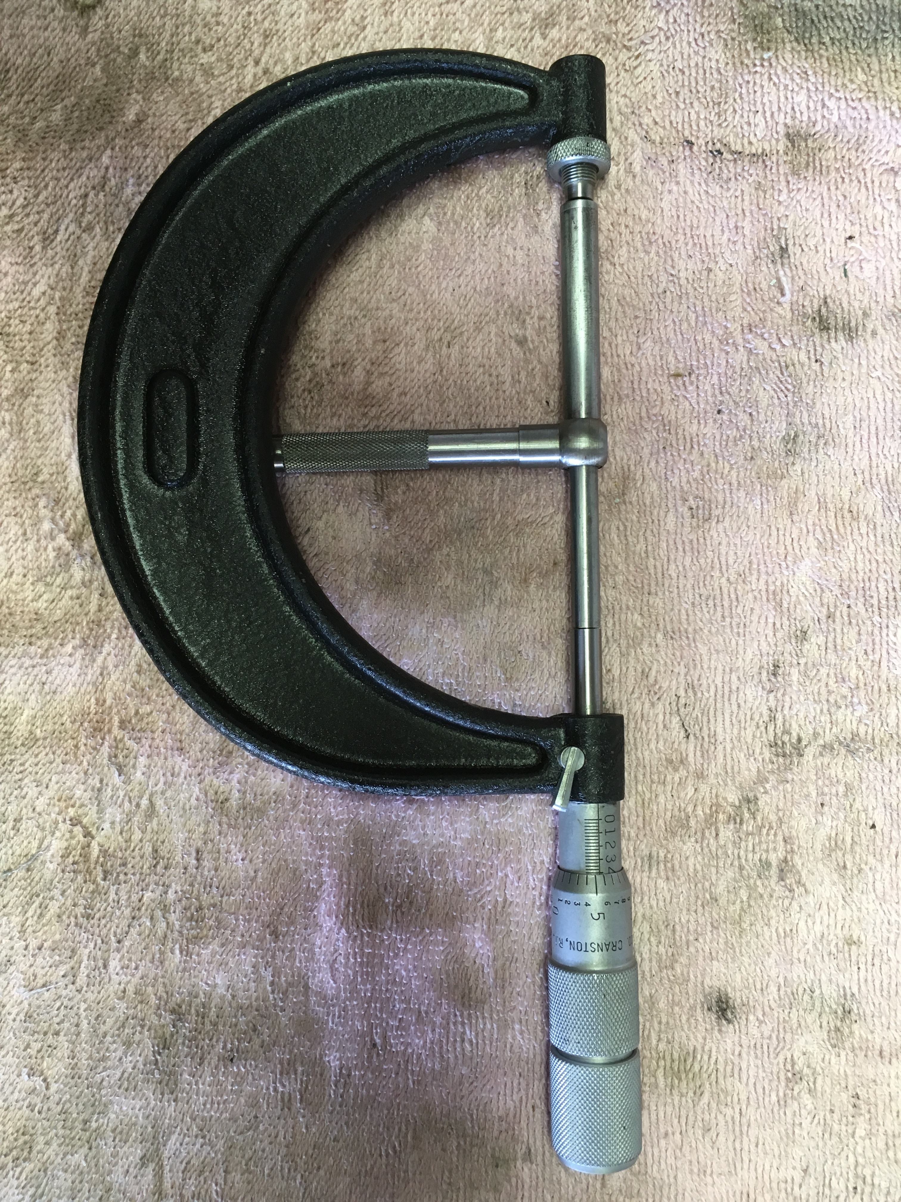
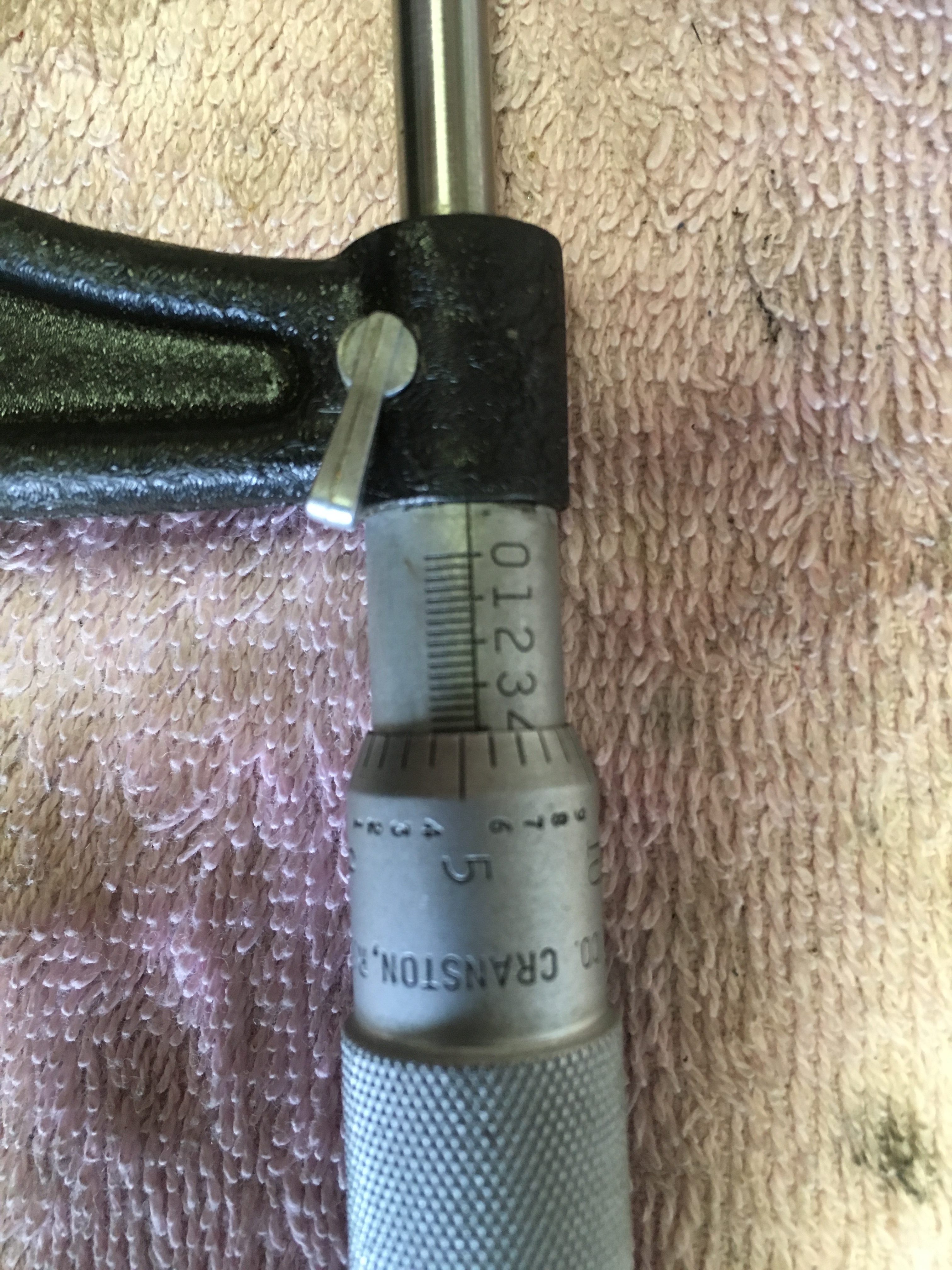
Oh, wow, Captain! That is a beautiful bore-mic. Probably still as accurate as it was when new, and I'll bet you're proud to own it. I didn't ask the machinist what the rods were off by and since I couldn't be as accurate as he with the tools I had, I had to go with the re-fit. Even if I had him leave the big ends together so I could measure them, I don't have a rod vise to hold the big end while removing the nuts. I probably could have used a vise without serated jaws, but there's no sense taking a chance on twisting the rod. The important thing is that when it all went together the plati-gauge crush was good and the crank spun freely. We didn't post these shots before because we want to keep the number of pix down to ten or less... Here are the orignial measurements for #5. Please correct me if I'm wrong, but I read that as somewhere between 0.0015'" and 0.002", according to the plasti-guage wrapper -- still within limits according to the Assembly Manual but it certainly locked up. You're right about the sound, too. With all six cylinders filled, now, the difference in effort to turn the crank is barely noticeable, between four and six; the whole assembly turns over easily with one hand. I might take a running-torque reading but I wouldn't have anything to compare it to if I did. Besides, that reading wouldn't mean much with larger diameter cylinders, shorter pistion skirts, and thin rings -- nothing is stock. Know where I can find a figure to compare to? I wish Matt was here to be in on the build.


-
Hi, Captain. Thanks for the question and the observation about plasti-gauge. Yes, I did the plasti-gauge crush check on each rod and finished each cylinder completely before moving to the next. The crush test on #5 was a little wide but appeared to be within limits when compared to the scale on the plasti-gauge wrapper, so I went forward with assembly. Number six was not as tight so I completely didn't expect a problem. You understand correctly that the crank bound up as I increased torque on each cap. Personally, I think the plasti-gauge wrapper is susceptible to shrinking and expansion with weather and temperature change. Add to that human error and tolerance stacking or decrease, and for me, plasti-gauge becomes almost the last insurance against improper clearances - the last being that you need to turn the crank as you tighten things up. As builders, we just need to make certain we're inspecting everything we can all along the way, the best we can. Unfortunately, my bore micrometer and some of my other precision tools went missing when I was building drone engines. Since I don't build engines as much any more, I didn't replace them and use snap gauges and micrometers for dimension measurements. The big ends of these two rods were measured when our parts came back from the machinist and I thought then that they were within limits. #5 & #6 had inadequate diameter measurements that I misread - very slight, to be sure - but that our machinist later confirmed.
-
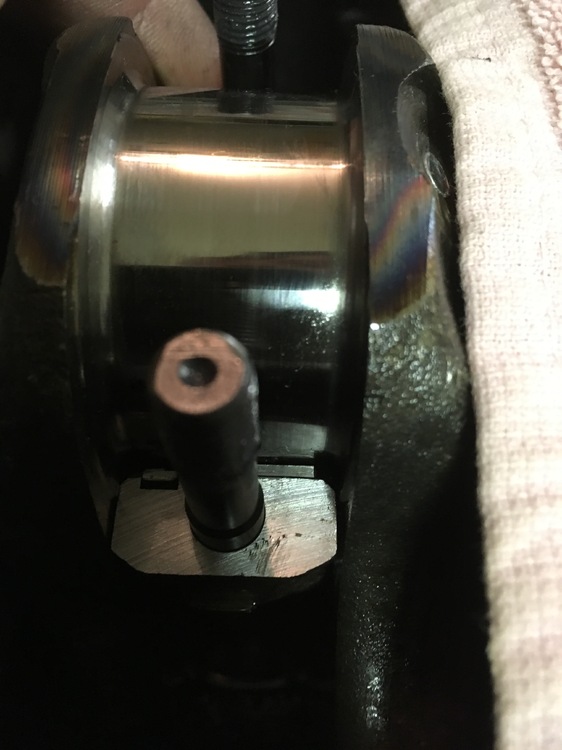
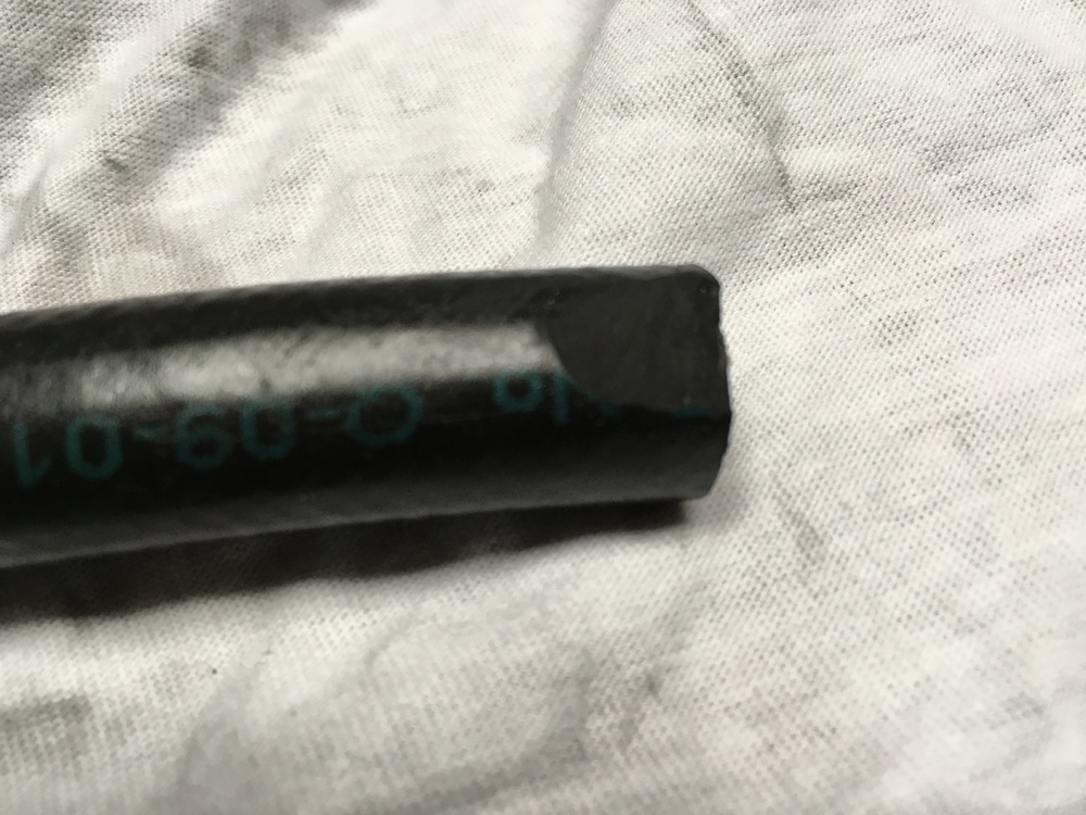
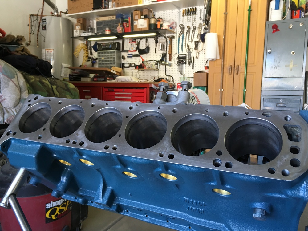
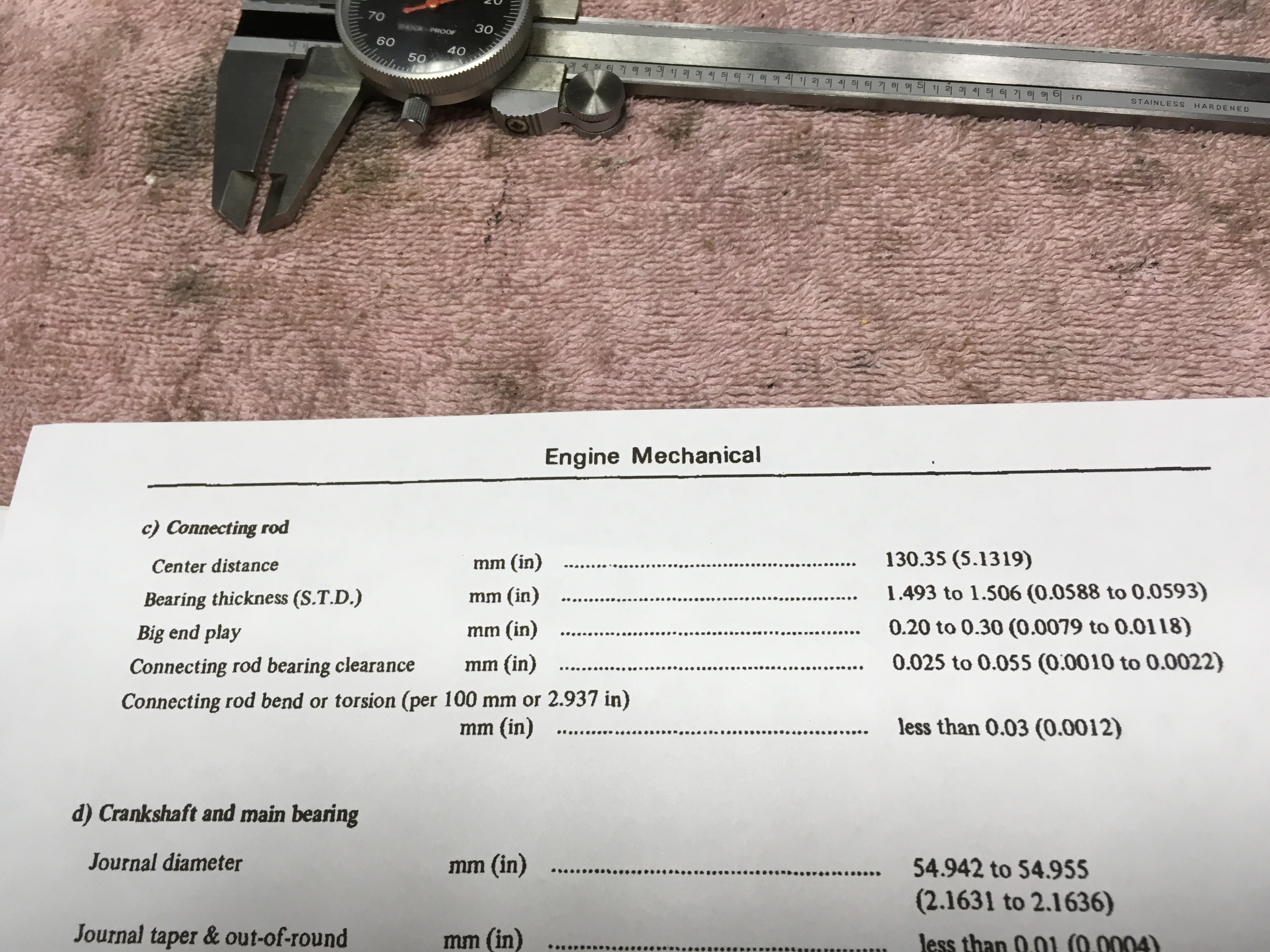
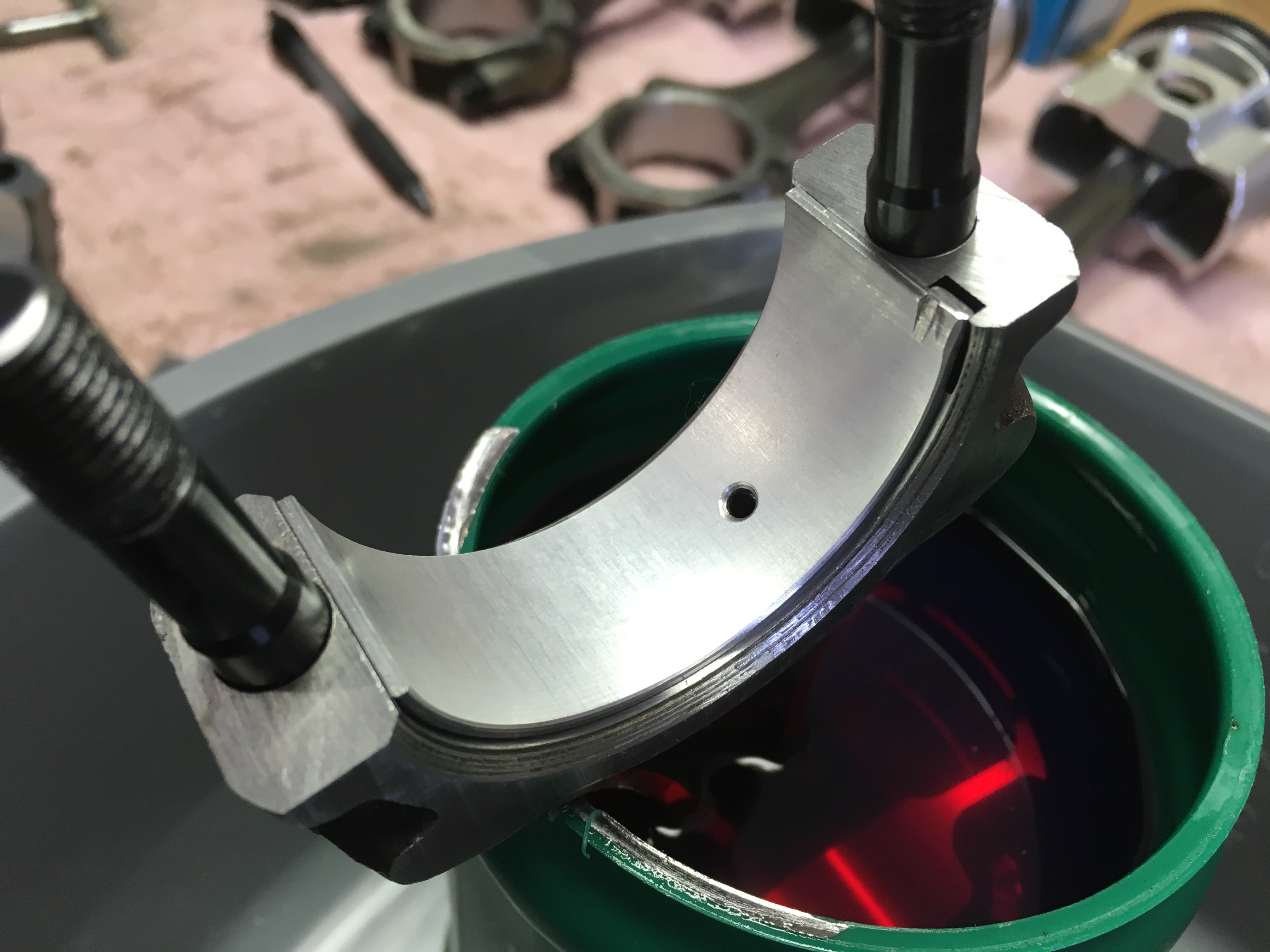
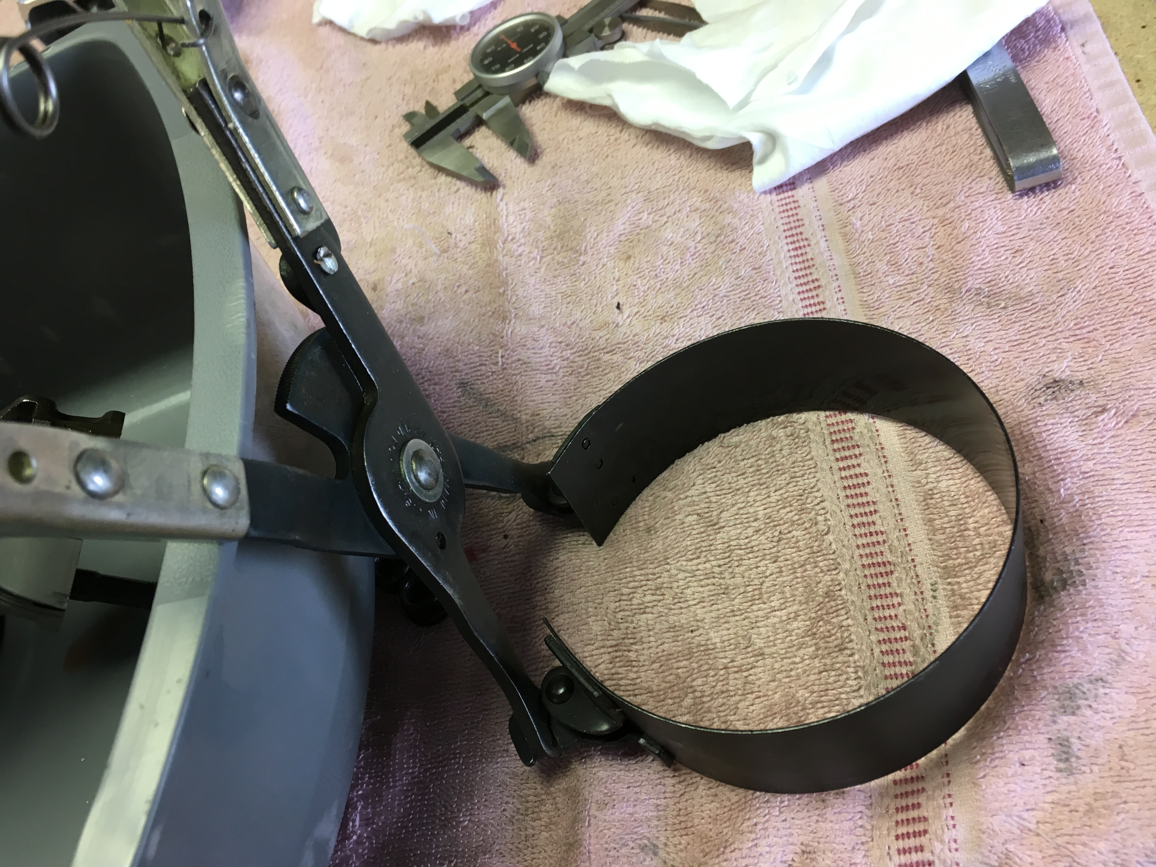
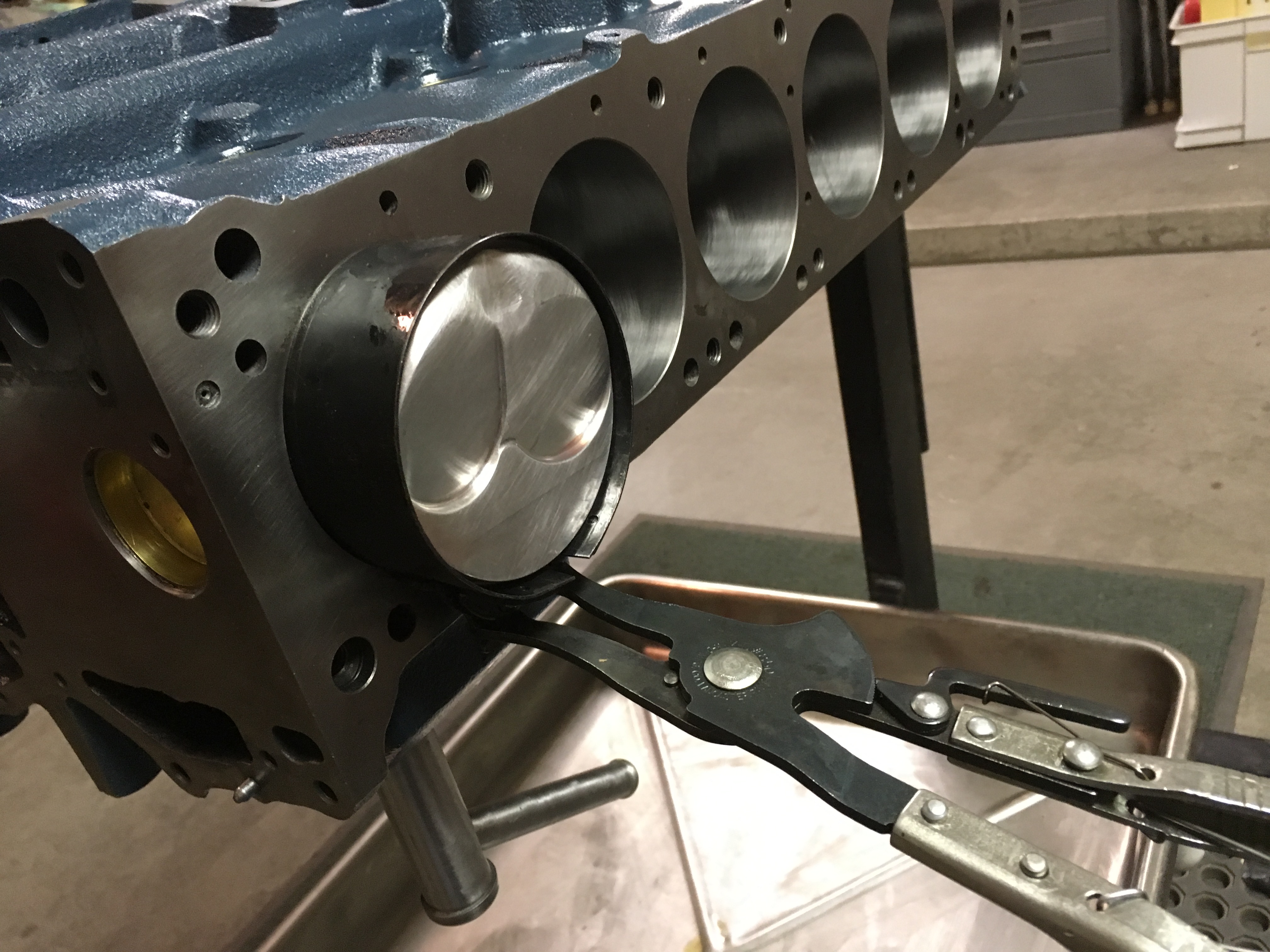
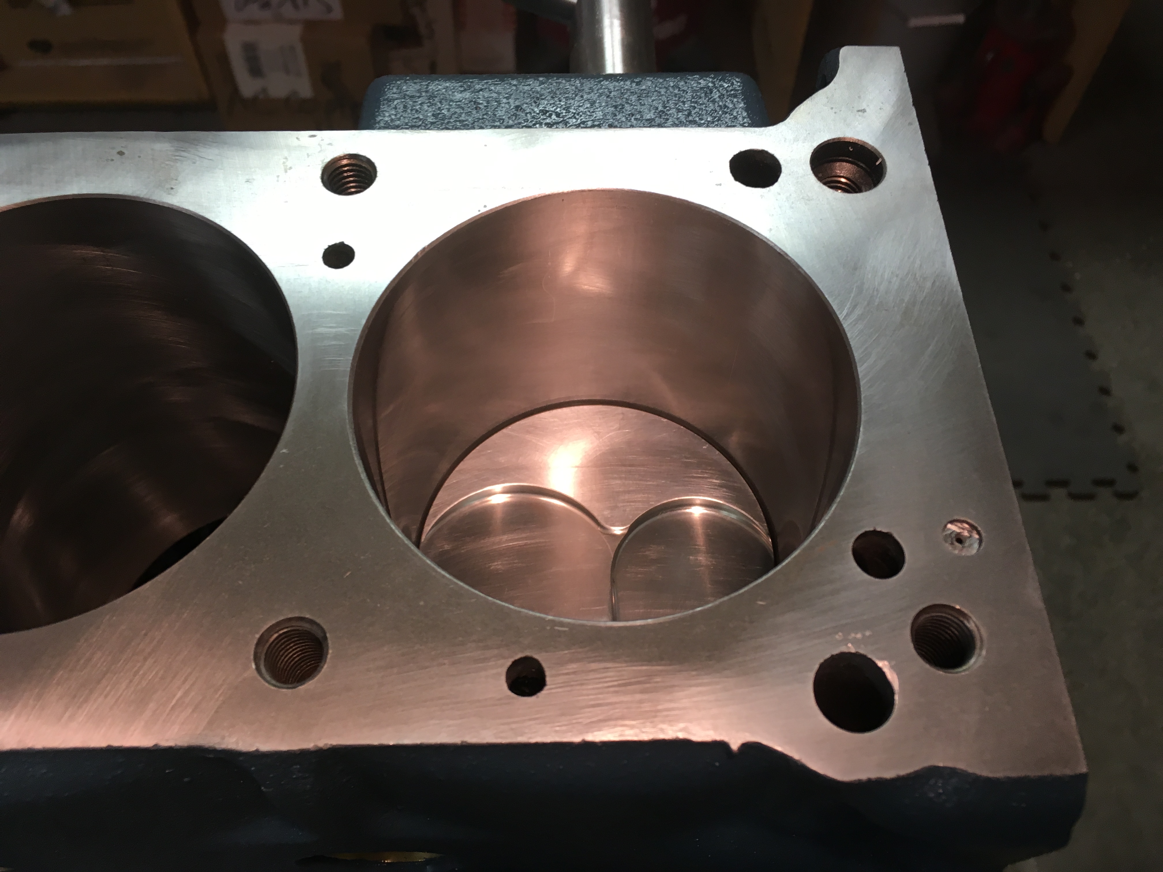
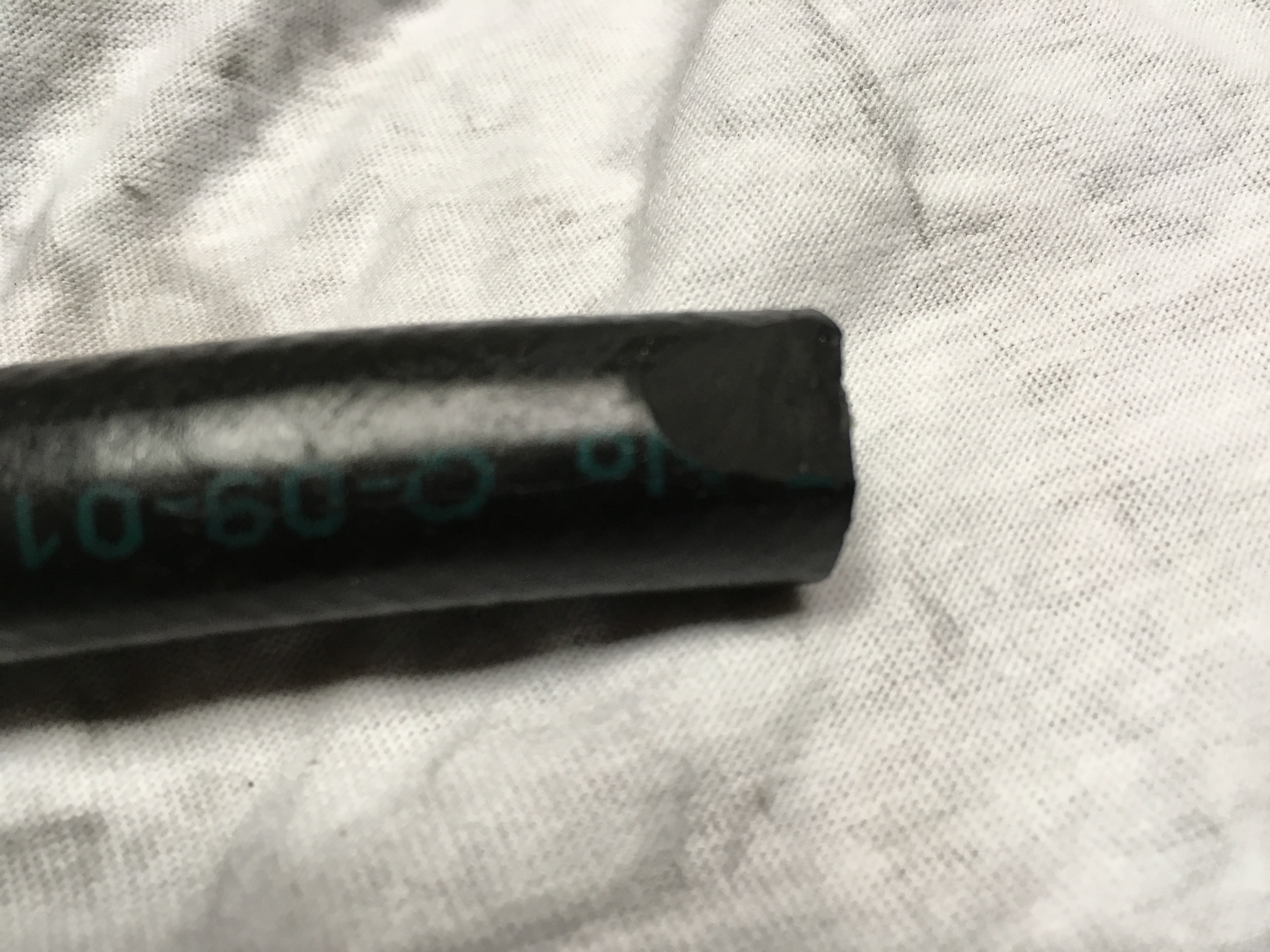
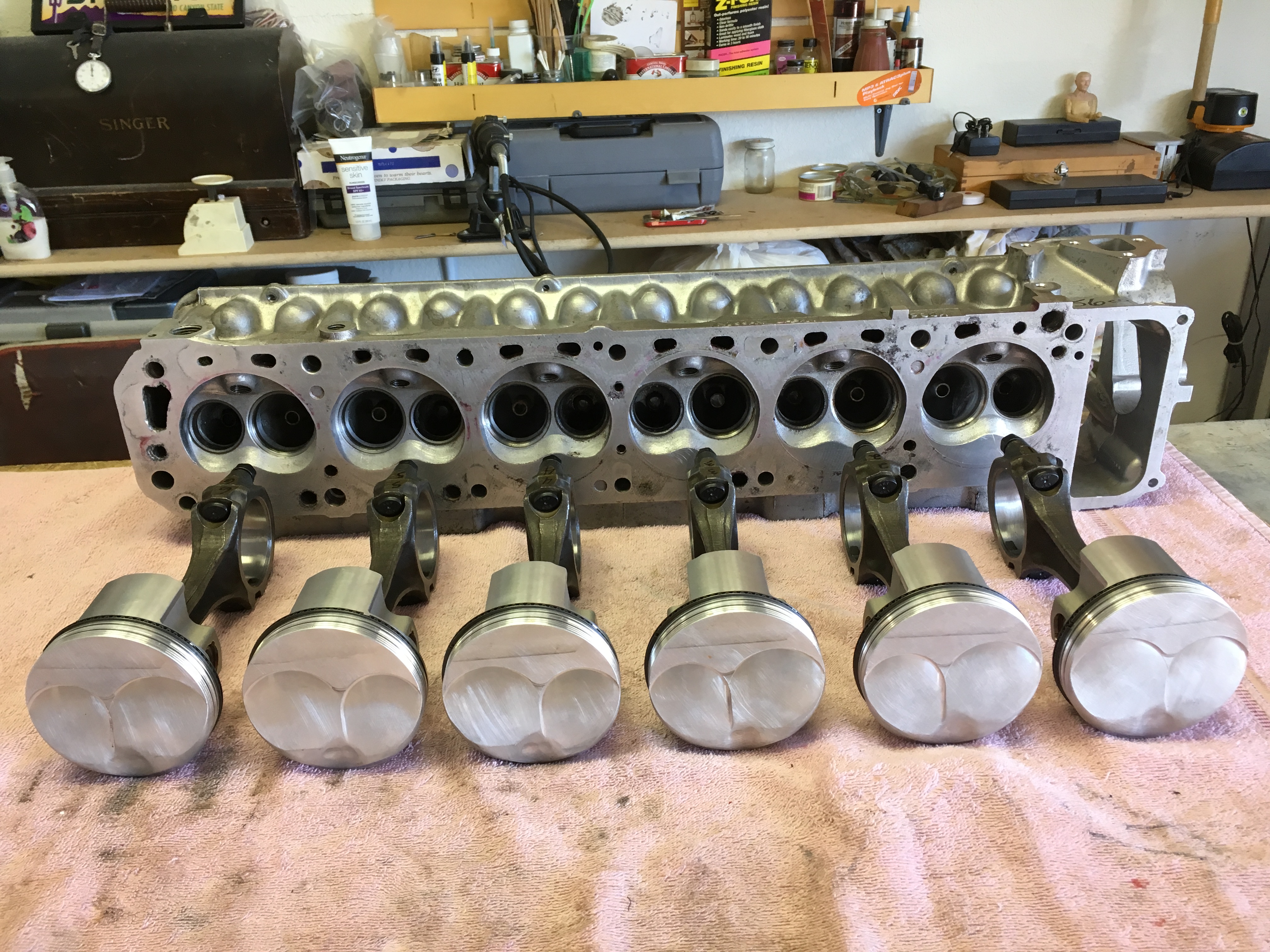
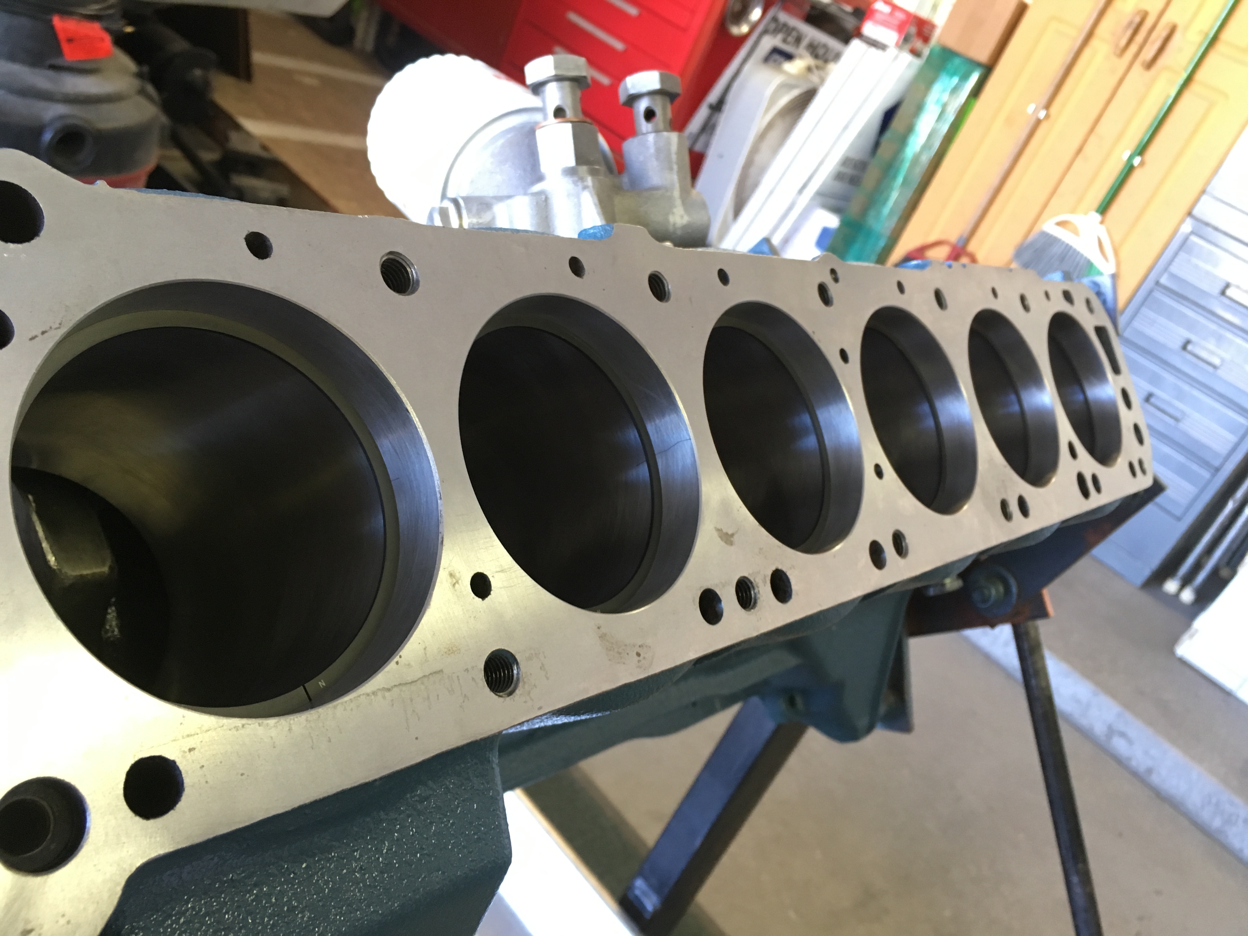
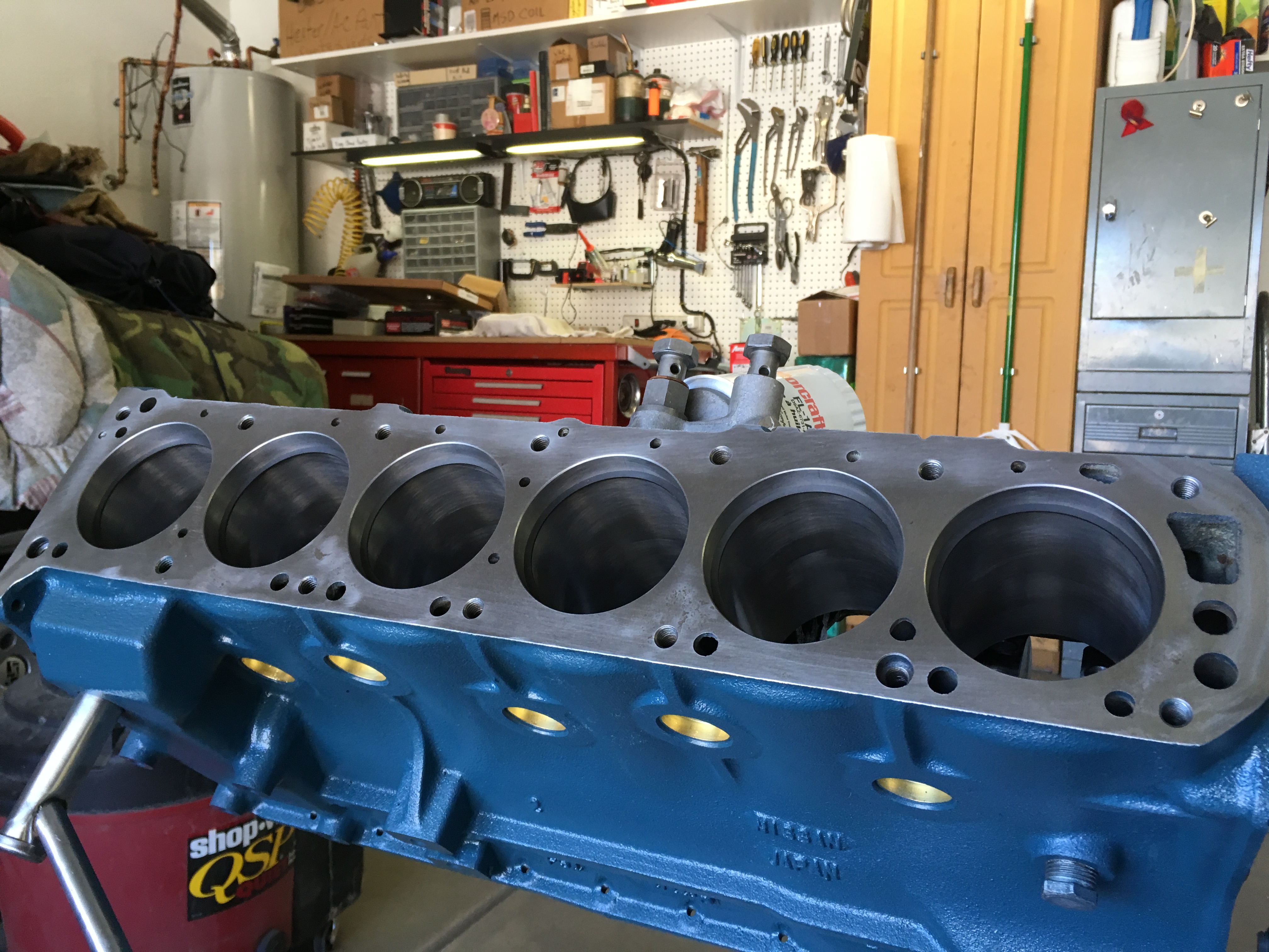
Engine Buildup: Rotating and Reciprocating Assembly Piston Installation With the crank installed and the cylinder bores wiped clean with acetone, the block was ready for pistons and rods. I prefer using aluminum tube or the threaded aluminum journal protectors you can buy. I had these for the 9mm rod bolts once upon a time, but someone decided they liked them better than I did. Without them, fuel line works just as well if you inspect for rubber debris before installing the rod cap. With the rings installed and double checked for proper clock position, I cleaned the rod end and set the bearing insert, and put the pistons into a bath of lubricant. JE’s ring installation instructions recommend Marvel Mystery Oil to lubricate the pistons during assembly and don't recommend using synthetic engine oil until after the rings are seated. Before putting the pistons in the MMO, I cleaned the oil passage in each rod with short length of stiff wire, followed by spray carb cleaner, to make certain each was clear of debris. Marvel Mystery Oil bath When I installed the #1 piston and rod assembly, I found the fuel line I used to protect the crank interfered with the rod journal as the big end of the rod moved over the crank. Not a big problem but I didn’t like the extra pounding on the piston needed to seat the assembly. I pulled the piston out and cut a chamfer on the hose – just enough to allow the rod to move over the journal. Don’t forget to lubricate the ring compressor! I brought the number one journal to Bottom Dead Center and Installed the piston and rod. The little change I made to the hoses let me push the pistons down the cylinder with just a little hand pressure, to seat the rod onto the crank. I watch for vertical scratches on the cylinder wall as I press the piston into the cylinder. If they are there I stop pushing because I know that I either broke a ring or I didn’t file a a ring gap chamfer well enough. The clock position of a scratch would tell which ring has the problem, but we had no problems with this on our build. I check the rod end to make certain the fuel hose didn't leave debris against the journal, lay on a strip of plasti-gauge, and install the caps. Assembly lube is used on the bolt threads and on the machined face of the rod cap. I use an pound/inch torque wrench and the Factory Engine Assembly Manual for the torque specs. Rod Bolt Torque can be as low as 360lb/in (30lb/ft) and high as 480lb/in (40lb/ft); I stopped at 35lb/ft then pulled the cap off for the plasti-gauge measurement. With each plasti-gauge crush check finished I cleaned the journal and bearing and pushed the piston up a bit. This opens a small gap between the rod bearing and the journal, so when EOS is pored onto the crank the assembly lube it runs down and wets the upper rod bearing insert. This way I don’t spin the crank with a partially dry bearing. Gap to allow EOS onto upper rod bearing insert, above. I moved through each cylinder with the same method until I got to number five, then had a problem... The plasti-gauge crush for number five was a little wide but appeared to be in tolerance, according to my calipers and the scale on the plasti-gauge wrapper – too wide means not enough clearance but the crush looked okay. As I mentioned before, I work in 50lb/in increments and spin the crank one full revolution between each 50-pound torque increase. Things were good until I completed 200lb/in torque, when the crank locked up. I pulled the rod cap off and found the edges of the bearing insert were slightly galled. The marks were very thin; only about 1/64" wide, right on the bearing's edge. I pulled the piston out and moved to number six cylinder, and – bad news! I had the same problem. We have a polished standard crank so we knew the crank was not the problem. The bearing inserts are correctly marked “STD” so I doubted the inserts were the problem, either. The rods and inserts were cleaned before placing the inserts into the rod and cap, so I was certain it had to be that the rod reconditioning was not quite correct. I left the inserts in the rods and took these two piston/rod assemblies back to the machinist. A quick check showed that the big ends of were just barely too small in diameter. The shop made the corrections and everything was good as assembly continued. More to follow... Cheers.


-
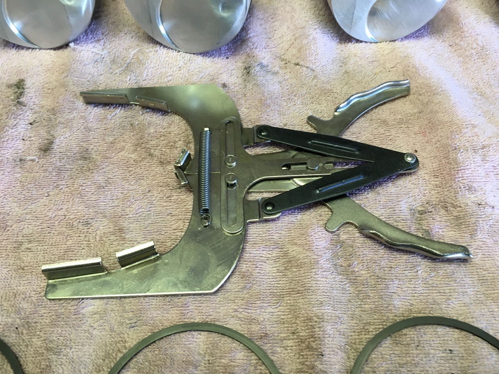
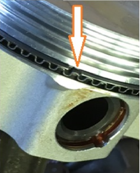
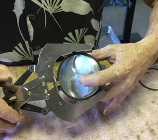
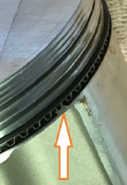
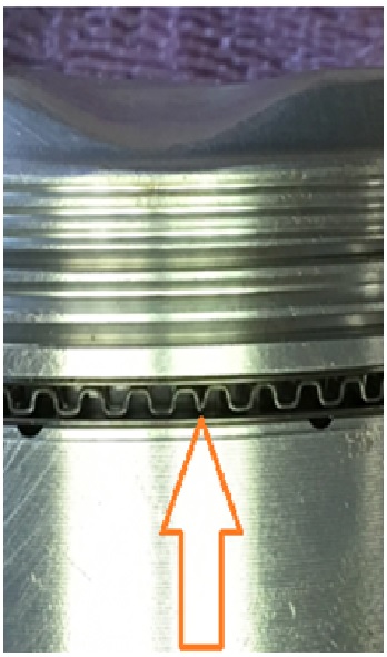
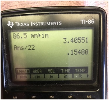
Engine Buildup: Rotating Assembly Piston and Ring Inspection and Preparation Okay, the lower end is all together but I want to touch on a couple of things I didn't mention... We don't want ring-bind so before doing anything I checked the ring back-clearance; You know,... the ring width subtracted from the depth of the ring groove. Also, I think it’s a good idea to make certain the right rings come in the package are the right size, so this check takes care of two things at once. The recommended “D-Wall” (radial width) dimension is in the instructions: Maximum D-Wall = Cylinder bore/22 Since the instructions indicate measurements in inches I converted the cylinder’s metric dimension first. So, JE recommends that maximum ring radial width of these rings should not exceed 0.1548” for an L-series engine; the recommended Minimum Back Clearance is 0.005”. I measured the ring groove depths, made a comparison with a ring width measurement, and our rings were okay. But I still double-checked with a straight edge. Installing the rings straight forward using all the precautions. The oil ring expander first, followed by the lower oil ring rail, then the upper oil ring rail. The only ring I install without a tool is the oil expansion ring. Some builders spiral the oil rails down the wall of the piston into the groove but the oil rails are thin, and flimsy, and easily twisted. We don’t want deformity during heat expansion so I use the expander for the oil rails too, and place the rings as I'm showing below, so the rings don’t fall out. I keep my finger over the back of the ring so that if it comes off the expander, it stays in my hands. Oil rail expansion ring ends go under the pistion dome. These rings didn't use a locator tab on the expansion ring. Lower and upper oil Rail locations spaced about 60°appart, opposite the expansion ring gap. Double check the side clearance and the piston and rod are almost ready to install.
-
Hello, "Site". Glad to know you're moving forward with your build, as well. I read that you need shorter stem seals with the high lift cams but didn't know were to get them; now I do -- thanks! Are you posting your build? Do you know theie height? We have seals in our gasket set and we're using a cam with 0.458" lift, so I think we'll be okay. I'll double check the clearence when I get to that point in the build.
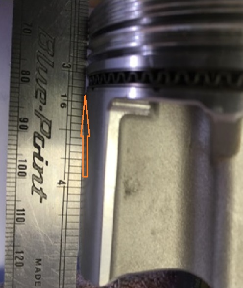
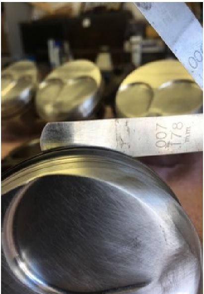
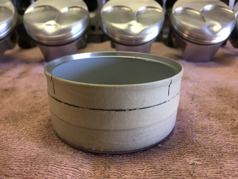
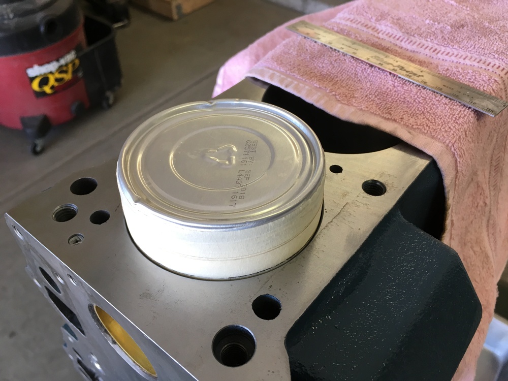
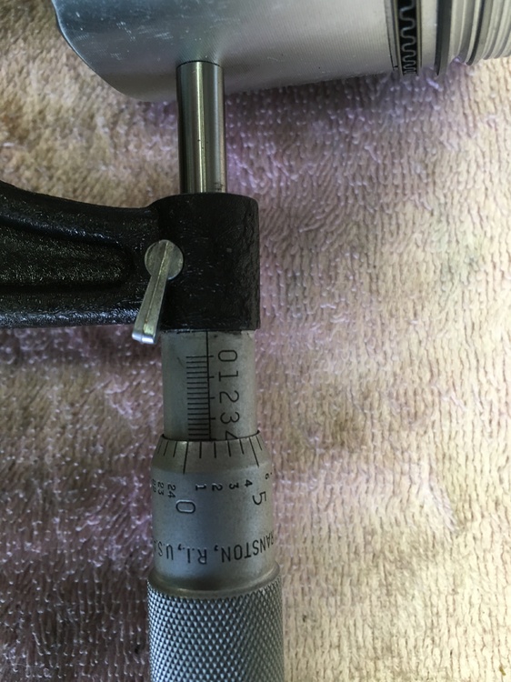
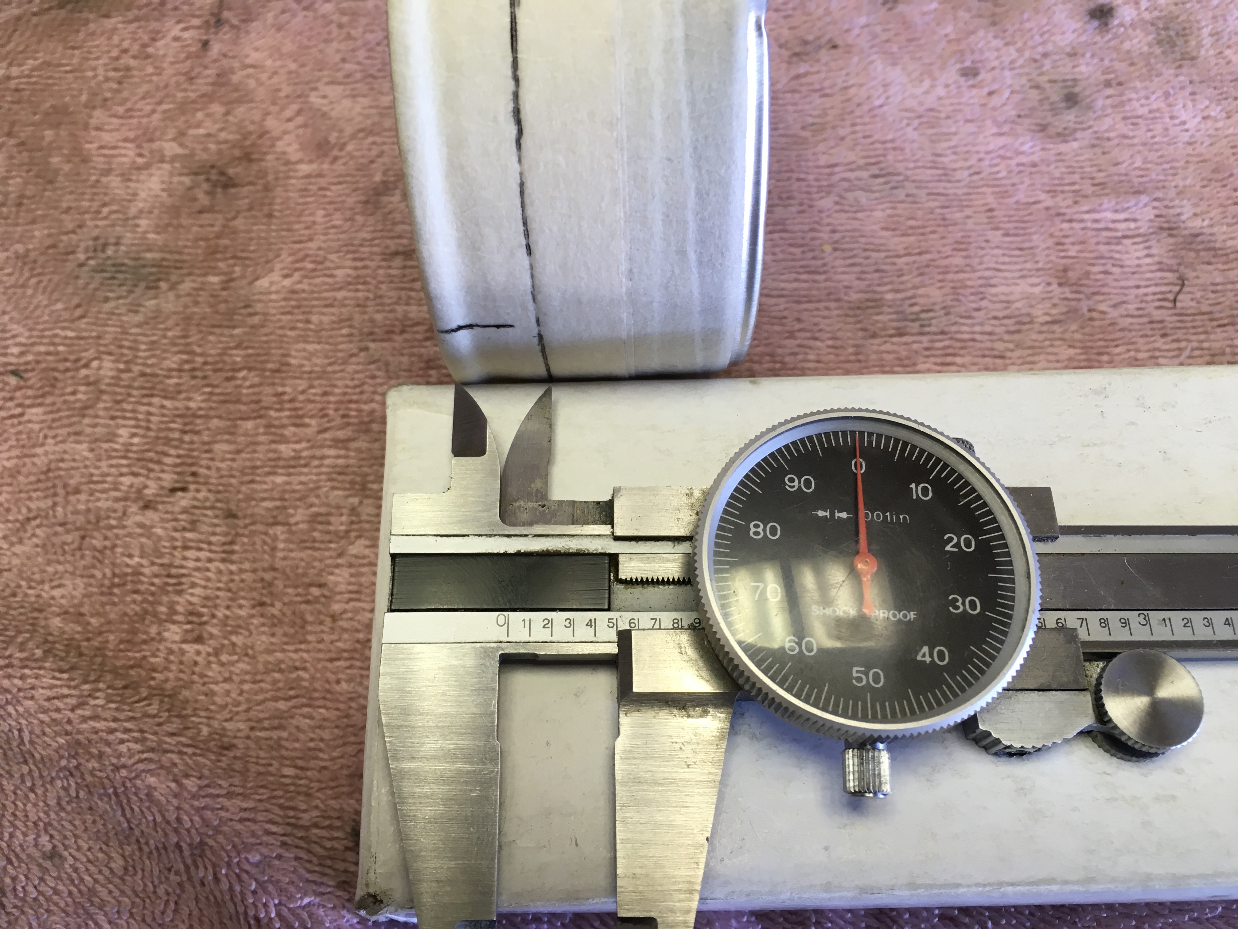
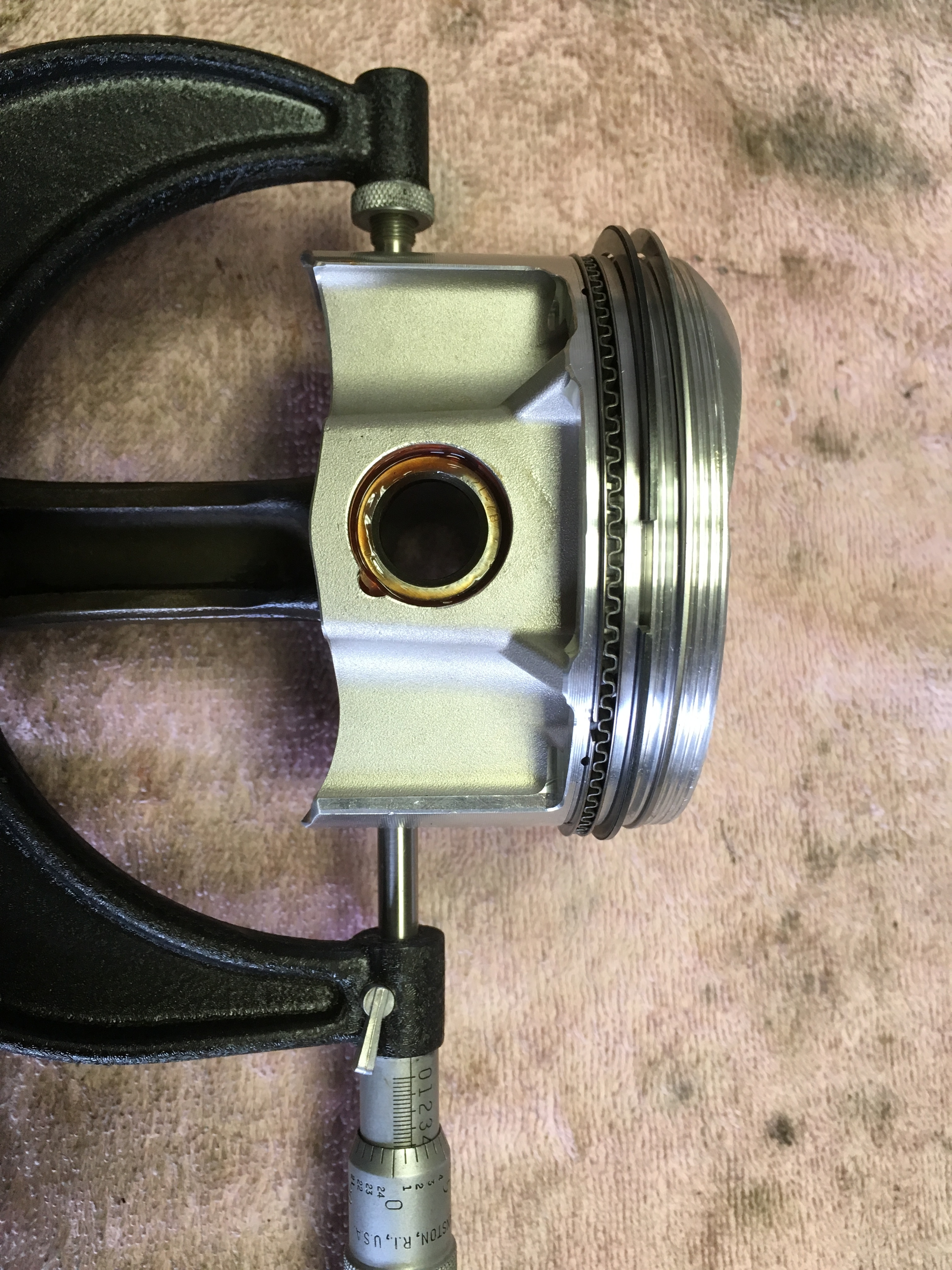
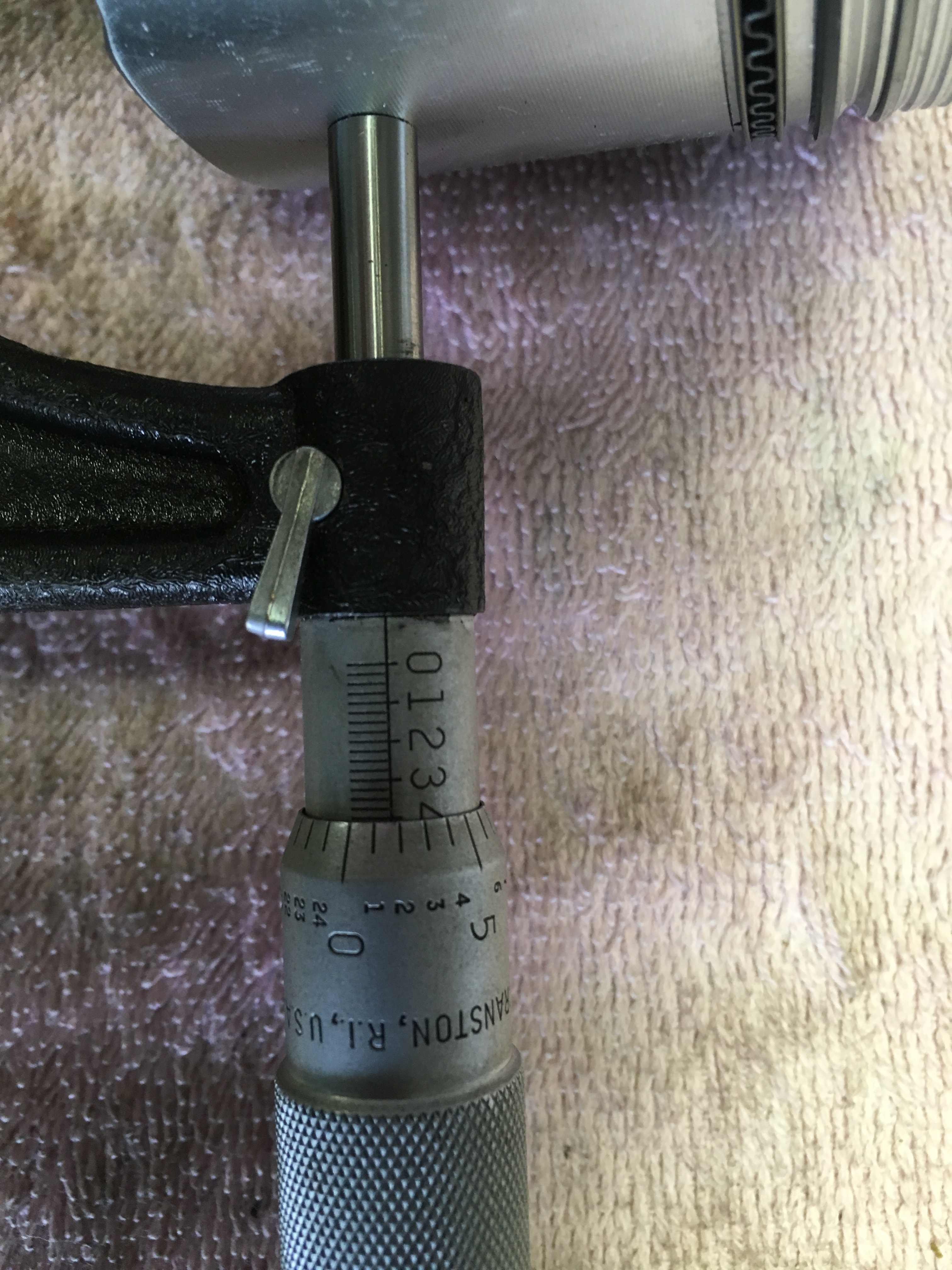
Okay... a little more of the assembly coming up. Piston and Ring Inspection and Preparation Before we took the time to install all the rings on the pistions, we checked the pistions were correctly installed on the rods. The rods are in the proper order front to back and the valve relief for each pistion is where it needs to be. With the crank in, it's the last chance to make certain the rods and pistions are assembled correctly and to measure the piston to cylinder wall clearance. It ought to be checked as soon as the block is clean, after the machinist is done, and for this build, it’ was. Here are the measurements... First, the cylinder bore measueasurement the old fasioned way... Here's a better view of the micrometer reading spool. Then we measured the piston skirt about one-half inch above the bottom of the skirt, but below the pin; we measured twice or more until certain, and measured each piston and cylinder. Here's a better view of the micrometer reading spool, for the piston skirt measurement. We needed 0.0035" and we are okay (if you see a mistake, for goodness sake let me know!!). Next it came time to gap the rings. We're showing the #2 compression ring here but they were all checked the same way. We measured the ring gap on each ring right out of the box, and to assure consistency we placed each ring into the cylinder at the same depth. But to do so, we had to make a little tool... Behold! One each cat food can; wrapped with masking tape for a soft but firm fit in the cylinder, and marked at one-half inch from the rolled edge. We place the rings in the cylinders a little bit below the deck and set the tool onto the ring... And, with a bit of a push down to the line we drew, the rings are all the same depth for measuring the gap. So, we had the rings in the cylinders and we took measurements; we didn't just start filing away at each ring to get the proper gap but made a note for each in our construction log, then looked for variations. We then swapped rings from cylinder to cylinder until things were as close as possible. Later we gently used the ring gaping tool and took measurements. I count each turn of the handle when I use the gaping tool and if I apply consistent pressure against the abrasive wheel, my cuts are pretty consitent too.we had what I want. We finished by dressing the ring ends with a small fine file and inspecting each end for burrs and sharp corners. I wear a set of magnifying goggles for a good close view. I'll have more pix of with the narative of the work coming up, but we're going to restrict the photos to ten or less, for now. Best to all, Takhli


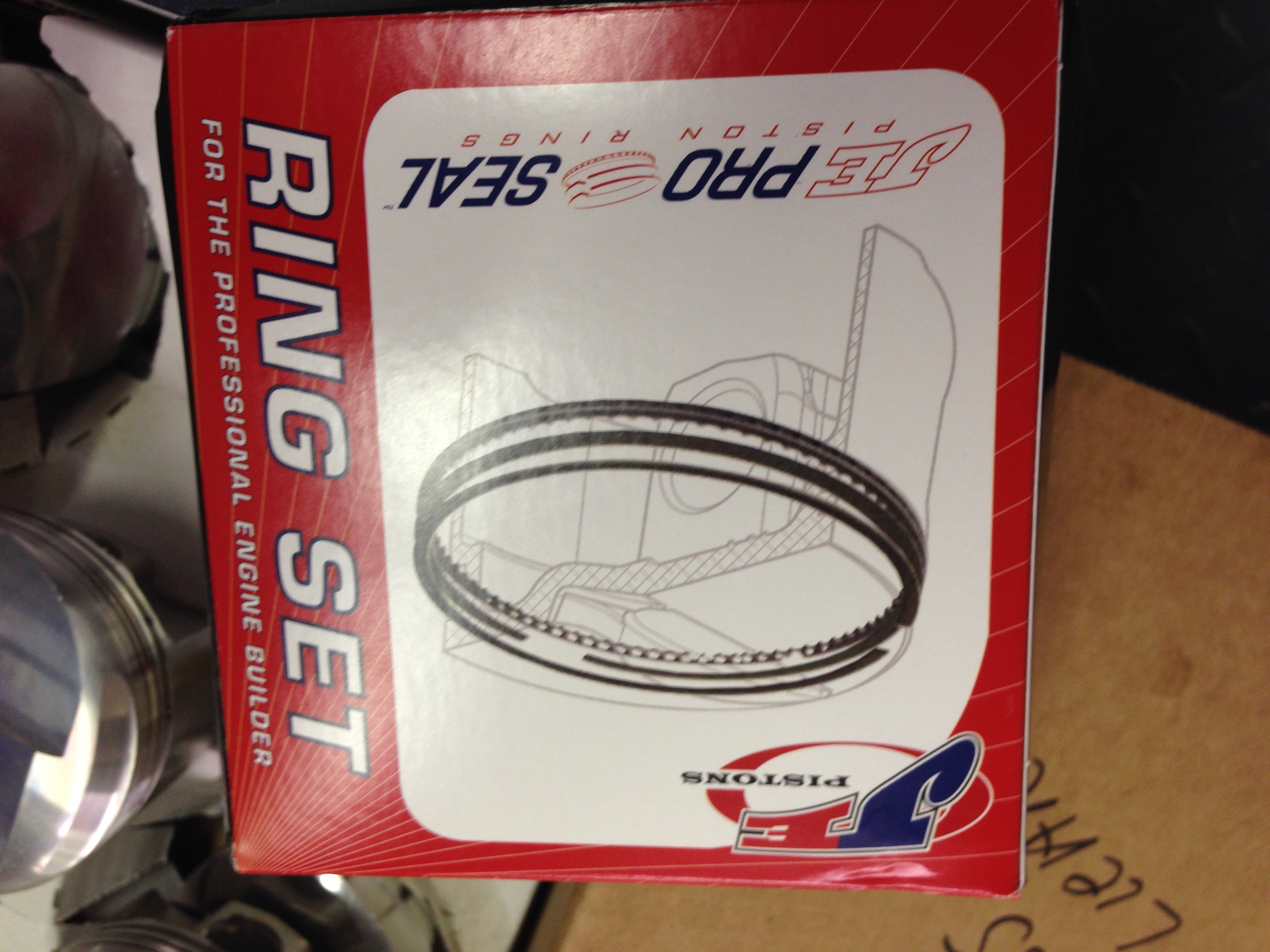
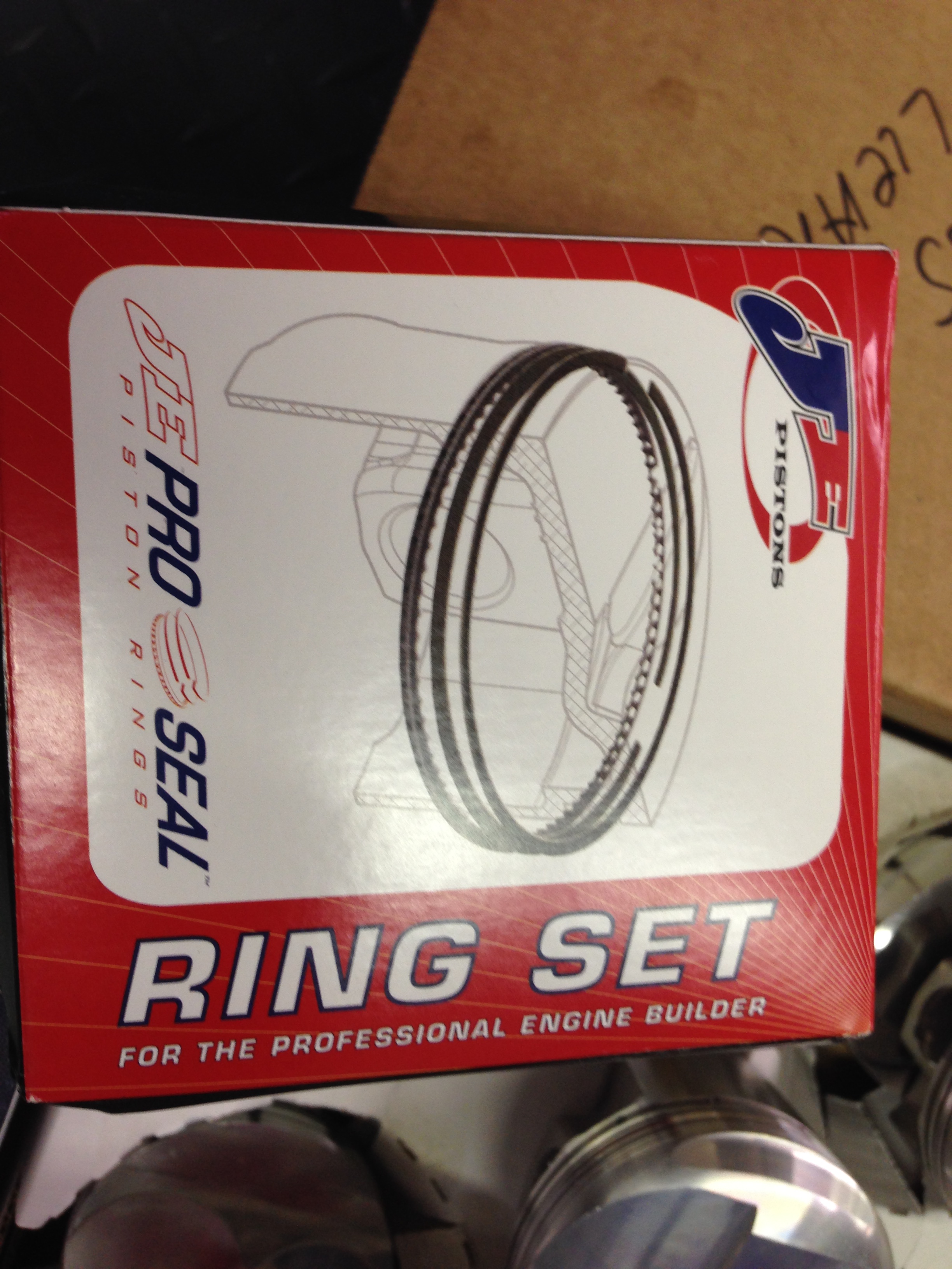
 The rings are JE Pro-Seal We've got a cross-hatch but I don't know what grit our machinist used during the final honing (I'll ask, 'cause I think that info would make Matt's build log more complete). I've never before installed rings like the set we used here. They were pretty much the choice of our machinist but they were also the ones JE talked with me about when I called them for info on ordering. Thanks for mentioning it... They have a Chrome Top Compression Ring,... a Moly #2 Compression Ring,... and then, what appeared to be a conventional oil control ring set. I think chrome rings are tougher to seat than molly, so this was an interesting configuration to me. I was taught that ring material determined the cylinder wall finish but I haven't had to actually bore and hone a block in years, and materials have changed. With the different rings here, I think we may have a slightly protracted break-in period. Again, I'll ask those questions and get back to you. I'll have more info on all this stuff, later. Cheers


 You know, Captain, I think it's a bit of Marvel Mystery Oil from my hand, but it could also be the light. You've got me wanting to go unwrap it, to look! I'll let you know, later.


Important Information
By using this site, you agree to our Privacy Policy and Guidelines. We have placed cookies on your device to help make this website better. You can adjust your cookie settings, otherwise we'll assume you're okay to continue.