


Takhli
Free Member
-
Joined
-
Last visited
Everything posted by Takhli
-
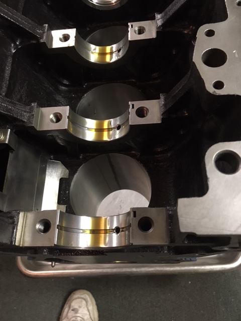
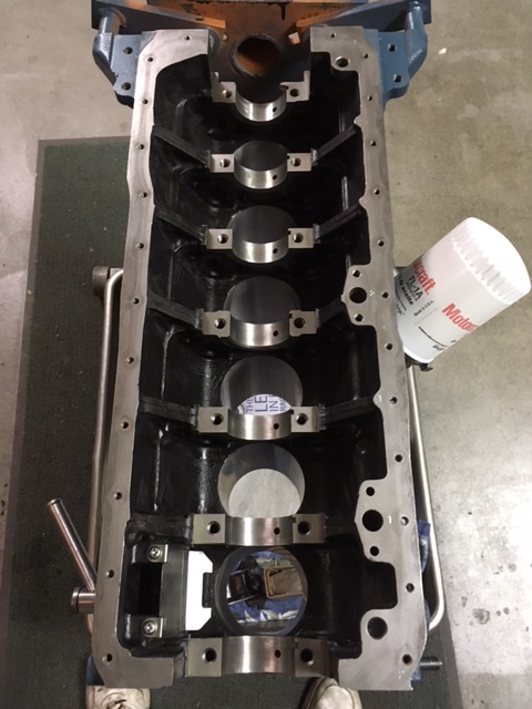
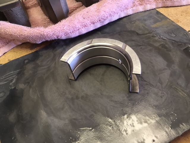
 Just a quick photo to show progress... Lower end is done. Nearly ready to close it up.
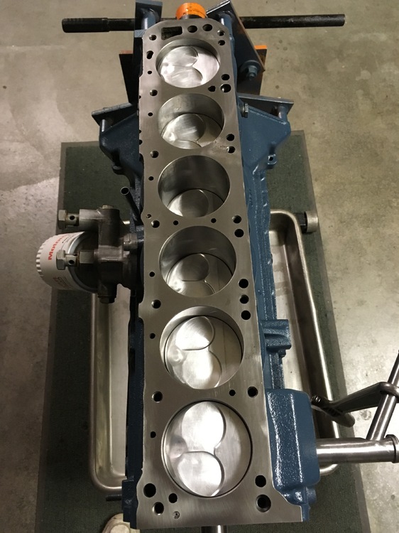
-
. Thanks, Captain! You bring up some very good points that I'm really glad you explained well. You're especially right mentioning that a novice could find him or her self in trouble using less than precision tools. I may look into that granite, too.
-
I agree that you are correct, and I appreciate that the Captain's recommended solid piece of milled granite may be very precise in its flatness. However, with the detail I'm providing here I didn't think I needed to explain that the building surface of my work bench is 2.5'' thick epoxy-coated hard wood that doesn't vary more than two thousandth of an inch over its 85'' length. It's a matter of practicality, as well - I used what I had. Perhaps "solid core door" and "dead flat" weren't the best terms, Zed, but the precision I achieved shows the surface and method to be unquestionable.
-
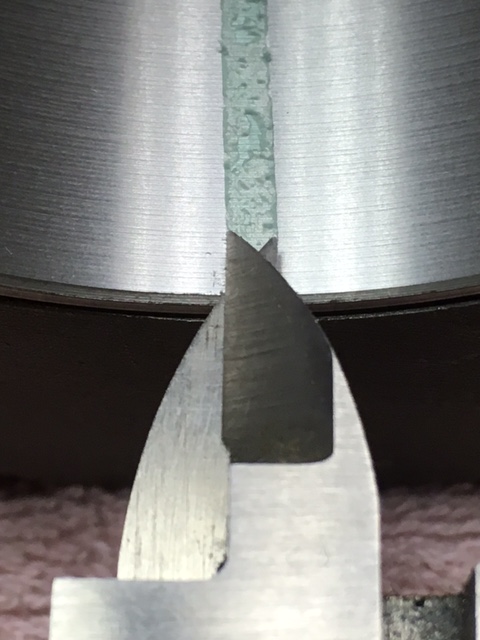
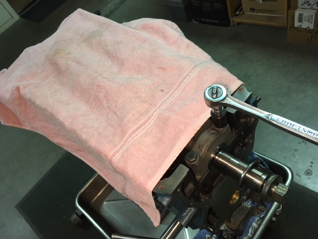
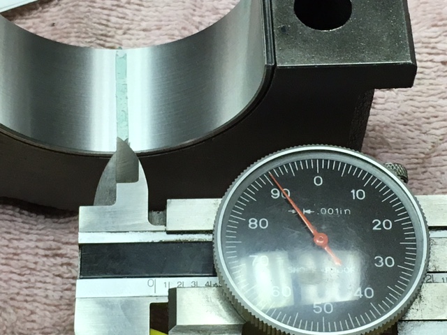
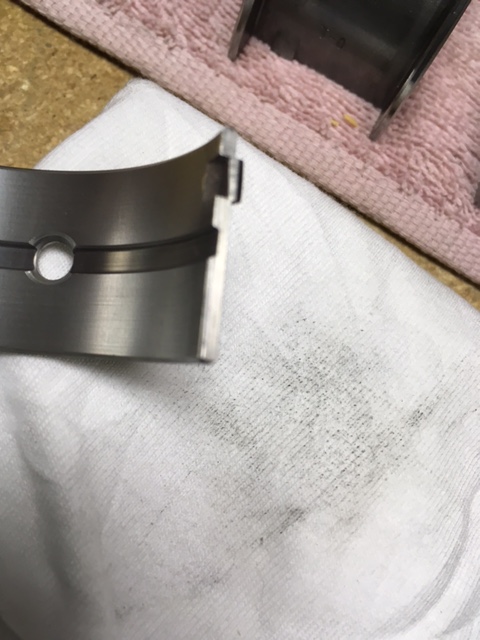
More on the short-block assembly... I left with the block ready for inserts. Inserts were installed and checked to make certain one edge was just slightly higher than the opposite side; this is important and there is a very good drawing in Tom Monroe's book. With the inserts in the block, the crank goes in against dry bearings. Green plasti-gauge is laid on each clean crank journal. The main caps are installed and torqued in sequence, per the Monroe book and factory specifications. I once had a coworker drop his ratchet into my work, damaging the crank; as you can see in the photo below, I lay a soft cover over the exposed crank to prevent inadvertent damage to the polished journals. Aside from keeping things clean, the towel helps prevent that kind of accident. . It's important to keep your thoughts on the job here -- If you're doing this kind of work for the first time, don't forget that at this point in the build the crank bearings are dry and you have a long semi-solid compressed between the crank and the bearing. If you turn your crank shaft now, you are likely to damage the bearing surface by pushing the plasti-gauge into the softer bearing material. Once the caps were torqued they were then taken off to measure the plasti-gauge crush. Number 4 cap and number 7 cap (the rear main) can be a pain to remove but be patient and think about what needs to happen. With cap bolts removed, I simply used a pry bar and small plastic mallet to loosen the caps. No need to insert the pry bar deep into the block's main cap threads - just deep enough to give leverage to wiggle the cap back and forth. Of course if you have the bucks to buy one, or the time and materials to make one, you can use the factory designed tool to remove these two caps. My point is, there are often alternatives to spending money and or time to do a job - especially if you use your head and take your time. Why spend money on a high-dollar uni-task tool when you don't need to? With the caps removed, measure the crushed plasti-gauge. I don't like comparing the marks on the plasti-gauge wrapper directly against the bearing surface - to me, it's clumsy - so I use calipers and record measurements. I still compare the caliper's measurement against the wrapper but now I don't need to hassle with the inside curvature of the bearing and cap. Matt's engine has a polished standard journal crank and for a performance street driven engine our measurements were exactly where I wanted them. If this engine was to be used for consistent track day driving I would have expected at least another half-thousandth clearance; another one-thousandth clearance for racing. With all my measurements verified, I clean the plasti-gauge from crank journals and bearing inserts, using my finger nail wrapped in dust free cloth. Soaking the plasti-gauge in acetone doesn't seem to help until 99% of it is removed. Then the crank comes out, the bearings are given a coat of EOS,... ...and the crank goes back in for the last time. Once again the caps are torqued to factory specs using the factory torque sequence pattern. During this final torquing process, it's important to spin the crank one full revolution after each cap is torqued. If the crank binds up, pull the caps of and find out why. And don't forget that the rear main cap gets a fillet of sealant in four locations before you install cap. I double check my crank shaft end play and then install the rear main seals into their vertical slots, while my sealant is still fresh and uncured. The Monroe book has good info on installing the seals so I won't cover that here. Now it's ready for the reciprocating parts. Questions are welcome. The next installment covers piston, ring, and rod installation. Cheers.


-
What would you recommend, Captain?
-
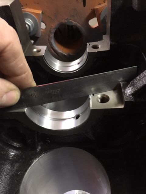
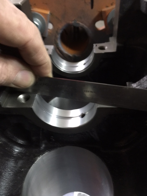
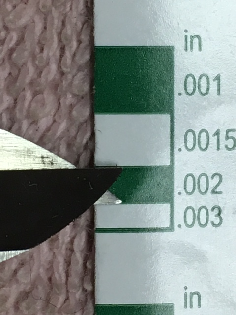
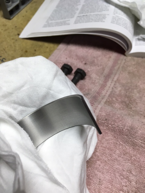
More on the engine build... Once the bearing inserts and block interior was clean the inserts went into the block and onto the caps. I started with the thrust bearing on number 4 main cap since, if the thrust bearing is too tight, there's no since in assembling all the caps just to take them apart to get the crank out again. The thrust bearing insert needs .002" to .007" clearence for the proper end play; as it turned out, the cap and insert went into the uninstalled crank journal with no problem but I couldn't get the minimum .002'' gap we needed. That called for surfacing the sides of the thrust bearing and when everything was reassembled I could easily insert a .003'' feeler gauge in between the bearing and crank throw; my final measurement after final crank installation showed that we have a comfortable .004'' end play. I have seen builders completely ignor the endplay measurement when building and they are asking for trouble. If there isn't enough clearance the thrust bearing will gall against the crank throw, at the very least. That means bearing material in the oil of their freshly rebuilt engine! However, when the thrust bearing surfaces are too thick you can't just start sanding away at the bearing's sides.... The method I use works preety well and starts with an absolutely clean, flat and hard surface. My bench top is a solid core door and, aside from engine work, used to build model aircraft -- I know its dead flat -- but a piece of 1/4'' glass works just as well. I lay a clean sheet of 320-grit wet-or-dry sand paper onto the bench top and saturate it with WD40 or Silicon Spray. Before the bearing hits the paper it is measured with a set of calipers or a micrometer and the measurements are recorded. I measure the thickness of each side as well as the overall width of the bearing, and during the sanding proceedure these thicknesses are checked systematically to insure the bearing stays true. I sand each side of each bearing-half four times. Placing the bearing-half on its side, the insert is pressed evenly against the sandpaper and worked in a figure-8 motion for eight to ten strokes. Then I take measurements. When the bearing insert goes back against the sandpaper it's rotated 180-degrees for the next session of sanding. Another set of measurements and the sanding is done again, this time with the insert placed 90-degrees to its previous position. More measurements and another sanding and measurment session. When I'm done with the first side and happy that the bearing sides are still parallel I flip the bearing over and do the same to the opposite side. Both thrust bearing inserts get the same treatment and my personal tollerance for my work is one-half of one-thousandth of an inch (0.0005") between the two halves. More on the short-block build up later. Cheers to all.


-
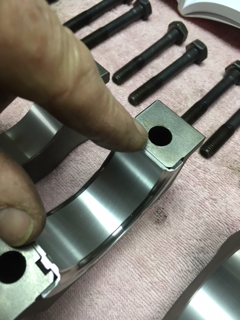
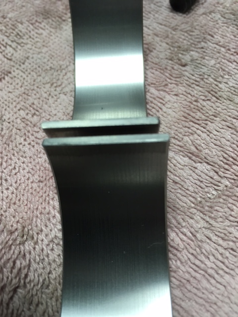
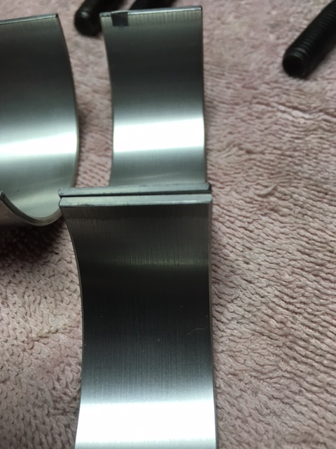
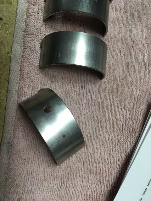
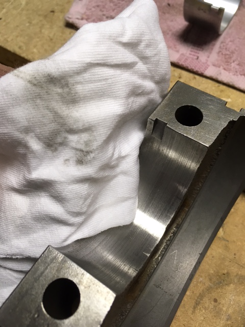
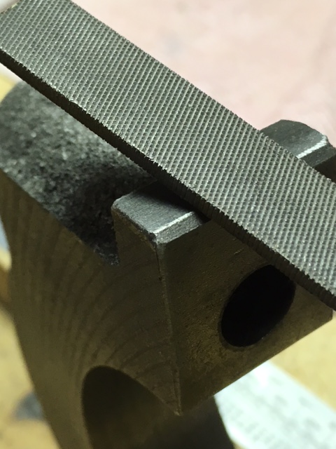
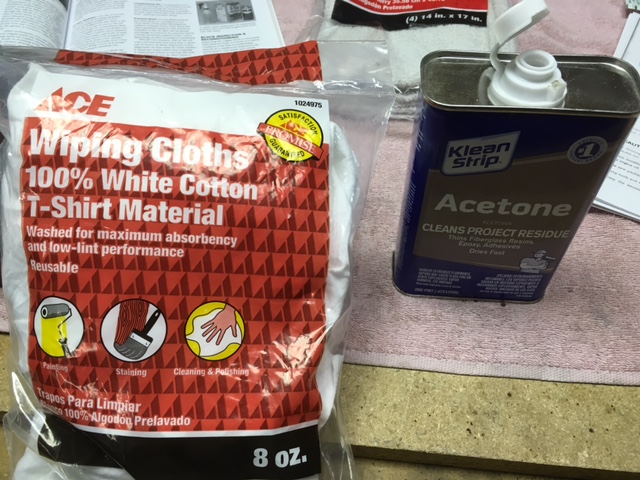
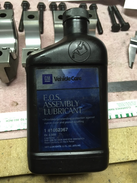
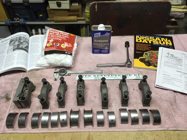
As you see above, I've done some assembly of Matt's short-block. Those with experience in building engines please excuse the detail but for the rest of you, following is the way it was done: Before beginning, I wash up thouroughly and take extra care to get my hands really clean. Also, I never build an engine while wearing gloves of any kind. That may seem odd to some but I like to be able to feel my parts as they go together and wearing gloves prevents feeling any grit or the tiniest particals that may find their way onto my clean engine parts. Gloves can also scratch the fine coating on bearing inserts. Next, comes cleaning my work area. I do not use compressed air in the area near my parts, but a dust pan and wisk boom to pick up the crud. Once the work area is clean comes setting up my organization and cleaning the engine parts. Acetone and dust free cloth are all I use for bare metal engine parts, and GM Engine Oil Supplement is what I use for assembly. I set all my parts and reference material in a clean dry location close to my assmbly area, then I begin an inspection of parts, regardless of them being used, recondioned, or new. Even if I've done an inspection previously. I also read my instructions several times before I begin. On the six-cylinder L-series engines it's important to note that the number 1 and number 7 bearing inserts are wider than the others. No so important to these engines is the small additional hole in the block insert that feeds the timing chain oiler. Our set of bearings came with this extra little hole in both the wider block inserts so I only had to make certain the inserts were in the proper bearing saddles. You may think that because you recieve parts in sealed packages they would be clean enough to install, straight away... Not so! The next few photos show the fine grit that came off the bearings and our main bearing caps with a simple wipe with acetone. Look closely and you will see that there is still residue on the towel after three passes with acetone wetted cloth. A word to the wise... Your parts cannot be too clean! Cleaning includes deburring the caps and making certain the flats on each boss are in fact true. Lay 400 grit wet-dry paper paper saturated in light oil on the CLEAN work bench and dress the flat, to gently remove any burrs that may have arisen during the block's stay at the machine shop. Then use a small fine file to dress the chamffer on the cap. When done, I clean the block saddles with acetone. Stay tuned... There's more to come.

-
Thank you, Namerow. Since the screen installation isn't documented well, I suppose I should also follow with the cleaning method I used. Its not rocket science but what the heck... When parts aren't available we need anything to save a few bucks and share what we learn. Note: The Factory Repair Manual provides neither a torque value for the retaining screws nor a method to clean the screen. First, the screws holding the baffle in place should be hard to remove. The screw heads accept a #3 Philips drive tip and a little gentle persuasion with a hammer and impact driver gets them out easily but Go easy with the hammer! On one of our engines these screws were also covered in an epoxy for a bit of extra security but I'm not certain that is needed if the screws are installed correctly. Second comes the cleaning. NOTE: The wire wrapped around the folded wire-mesh may be bonded to the screen with something like JB Weld epoxy, or it may be micro-welded - I've seen both methods. The micro-welded part does not come apart easily without damaging the wire-mesh, so a new part should be considered if available. If the wire mesh has never been removed from a high-mileage engine, expect the screen material to be covered in a baked on hard varnish. For me, the best way to get this off is a very long soak in carburetor cleaner. Drop the screen in the cleaner and forget it for a week. I lucked out and have the screen that used epoxy. When it comes out of the cleaner the bond should be loose enough to separate the wire from the mesh. That's a good thing because you can now unfold the wire-mesh and really inspect it for damage and debris. Rinse the mesh in hot soapy water then rinse it again with a spray carburetor or brake cleaner. Next, re-fold the mesh into its original shape making sure that the folded screen retains the original shape and fits into the cavity properly. Use JB Weld to rebond the retaining wire around the mesh and let the JB Weld cure. The threaded holes for the retaining baffle, as well as the screws themselves, must be clean and dry before installing the screws. I clean the hols with a rifle cleaning brush when I clean the block but, if you're not doing a rebuild that requires machine shop work, the threads can be cleaned with spray carb or brake cleaner. When the breather baffle-retainer goes back into the block, apply Red Lock-tite to the screw threads and torque them securely.
-
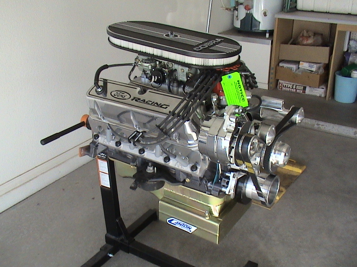
Eastwood primer, high-temp aluminum engine spray, then clear epoxy coat
-
-
Gotta love before and after pics! I love this hobby!
-
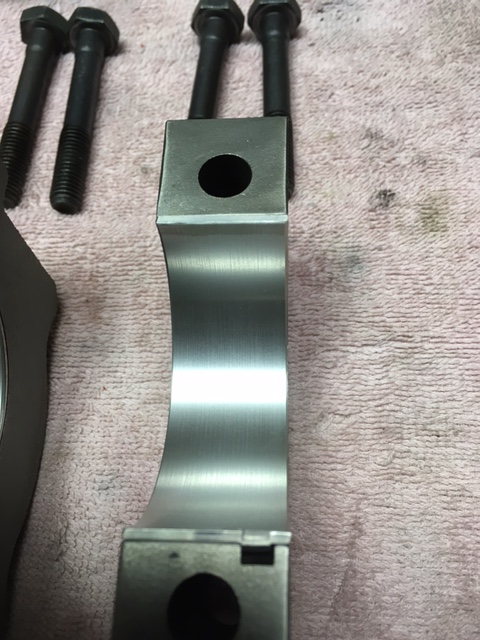
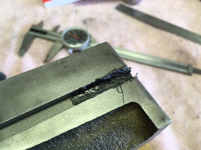
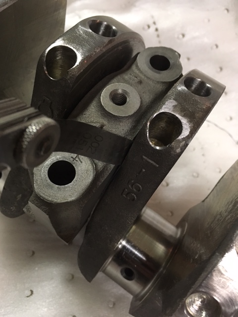
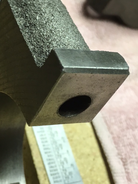
The damaged area was ground away and the threads were chamfered. What you see below is the cap "in-work". More chamfering was accomplished and the oil seal drain area was smoothed and polished out. Nothing wrong with it because what was ground away doesn't affect the strength of the cap.
-
I think you'll be fine with the mechanical pump, Matt. Not certain on how to re-jet the SU's and they may use needles, too, but they should handle the additional 220cc's with no problem. Also, they cannot be much more difficult to work than the carbs we modified for Betty. If you were going to make the engine live and work consistently at high RPM, that would be different, but we'll use the larger fuel lines to handle the fuel volume and work the carbs to provide the necessary mixture.
-
Like I said; we had to go with custom pistons because we're using the longer, early production L24 rods.
-
Piston design was a surprise to me as well. Very interesting concept that J&E used. Don't know if other pistion builders are following suit or why they chose to employ the design on Matt's pistons; we simply took down the numbers and told J&E the compression ratio we were looking for. Hell,... for all I know we could be an experiment! But according to our machinist the ridges help eliminate "Black Wall"; that's a term I never heard prior to two weeks ago and haven't investigated. But, I think it is a varnish of fuel and oil caused by too much heat at the top of the cylinder, that can extend down into the ring area to screw up the ring seal. As far as my experience goes, I've built engines since high-school - professionally as an employee and for my personal and friends use. That includes experimental development of drone engines and a cylinder head teardown on an L24, years ago, but mostly I'm a pushrod engine builder and this is my first L-series rebuild. Different OHC engines each have a pequliarity and their assembly and modification need to be well thought out. Research and investigation are the keys as well as measured self confidence. My method is to ask the right people the questions I have, get second oppinions and read everything I can get my hands on.
-
Also, don't want to have issues with cam height. The deck is 0.003-inch lower already. When we surface the head to get our target chamber volume we will also need to surface the top of the head to make certain all the mating surfaces and cam towers are square with each another, so we're probably looking at more than 0.030-inch of metal removal. If we go with heavier surface cut to raise the compression we were looking at the possibility of swaping the vavles - an un-needed expense for a car that won't see track time.
-
Max RPM around 6500; want a car he can drive anywhere without gasoline issues and pinging.
-
Hi, Madkaw. The rods are Datsun units, 133.0mm center-to-center, used in the early 240's, where as the 280s use 130.35mm. Anyway, the extra length provides a better stroke to pistion diameter ratio because there is less side thrust. As for the pistions, they came from J&E without the sparkplug boss relief in the dome. We had to lay the piston against the head to identify clearance issues. We could have taken a clay mold of the chamber and sent it into J&E but that would have driven the price of each piston much higher. As it is, they were $105.00 each.
-
Choice of Block and Cylinder Head were Matt's. The choice of rods - the longer factory stock 240Z variety - was a colaboration between the two of us. Pistons were custom designed due to the combination of parts chosen, with the dome volume prescribed by the gasket and head, for approximately 9.85:1 compression ratio. Once I've done a preliminary buildup of one piston, I'll be able to provide absolute dimensions. BTW: For anyone thinking that all P90/P90a cylinder heads have chamber volumes of approximately 53.6 cc, they should think again. Our machinist and I cc'd three different P90 series heads and found a variation of 4cc's or more between them. The P90 we have has been milled and still holds about 55cc's, while each of our stock P90a's have chambers between 55.8 and 57.6 cc's. On Matt's engine, I will use a P90a's with about 56cc's and equalize each chamber after I accomplish pocket porting and port matching. I'll install a cam, do a valve clearance/dome height clay check, and then the head gets sent to the machinist for minimum material surfacing - about 0.003-inch - to clean up areas that needed weld repairs. I expect this head to have about 55cc's volume when done.
-
Okay, guys... I'm building Matt's engine and, although a response may not come at light speed, I can answer almost any question you may have about his engine's build. Right now, the block and rotating assembly are as Matt has posted in the photos... Bearings were ordered today and I expect them by Saturday, so the buildup should begin soon there after. What's left before we start? First, we take a highspeed grinder to the casting flash in the crankcase. Tape and plugs will cover all the oil passages in the mains and up to the top end; then, the main oil gallery expansion plugs come out so I can tap the gallery for plugs. I have to do this because, as you may have seen in the photos, our machinist fabricated and installed a plug in the oil bypass: I want to make certain the gallery is absolutely clean so the plugs come out to provide access to the rifle cleaning rod and bristle brushes I use to clean the passage with. Every bolt hole on the block will recieve a chamfer as well, so that threads aren't pulled. When all the grinding, cutting, and tapping is finished the Block gets a major bath with high pressure soap and hot water, followed by a good coating of WD40 to prevent flash rust. I haven't decided to seal the casting with Glyptal, but probably will not. Assembly documentation and photos will go to Matt for posting so he's first in the loop of information. Cheers.

