qz16
-
Posts
147 -
Joined
-
Last visited
-
Days Won
2
Content Type
Profiles
Knowledge Base
Zcar Wiki
Forums
Gallery
Events
Downloads
Store
Blogs
Collections
Classifieds
Everything posted by qz16
-
I am going to have to move the hatch toward the front of the car. More on the right then the left, this i fear will only make the clearance issue worse. I also hope that adding the weight of the glass will not impact the lift of the piston. By inspecting the tabs I gather you mean remove the hatch completely or can i just take the screws out and get one hinge out of the way? I guess I really need to look at both sides of the hatch tab. Thats going to take a bit of time as I will probably need a second set of hands to remove and install the hatch. I will post images of the tabs when I have them. Thanks again. edit: Okay so I just took a look at the tabs and they are painted, which means they got a good look over when I sanded them before I primed and and sprayed color. I am fairly certain that they are in good shape. I probably would not have noticed if they were slightly bent, but a bad weld would not have escaped me.


-
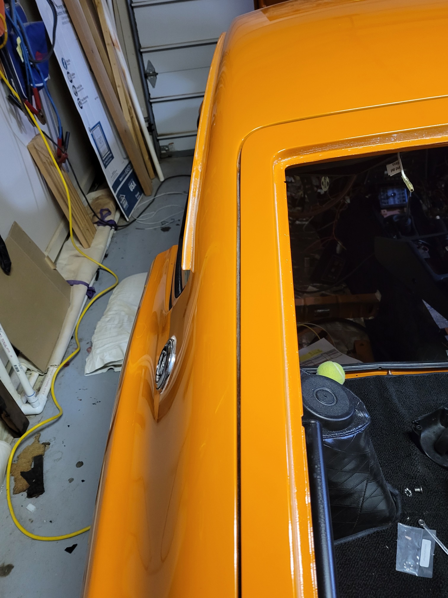
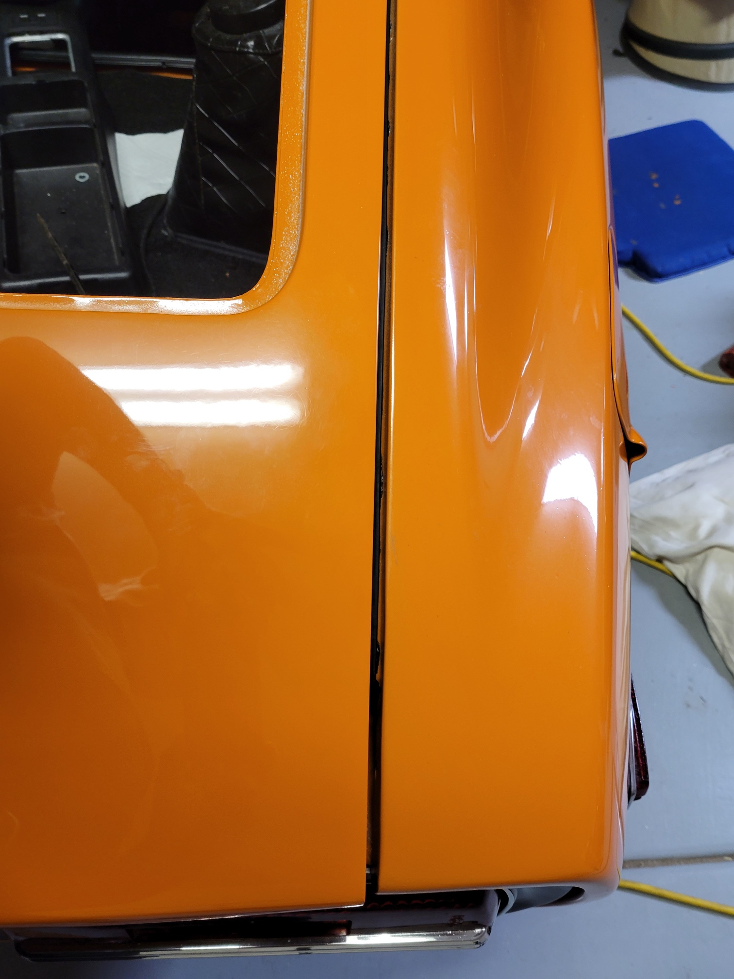
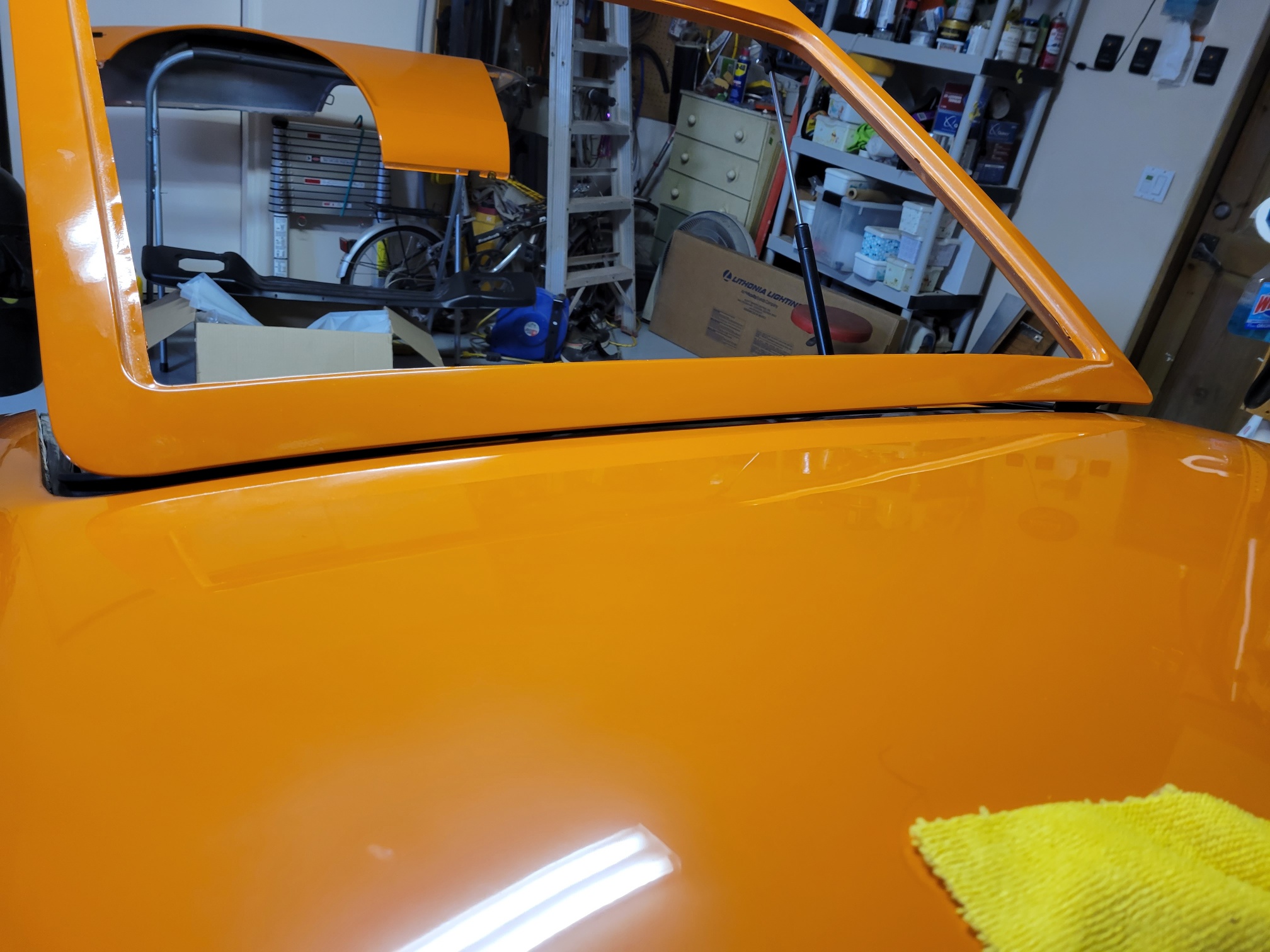
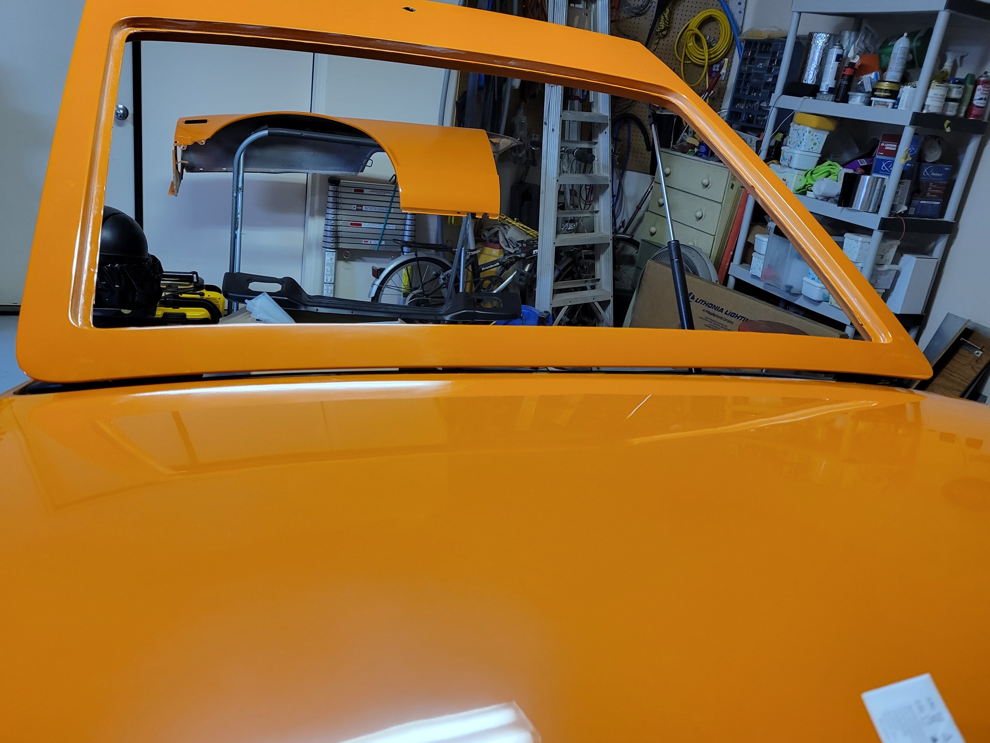
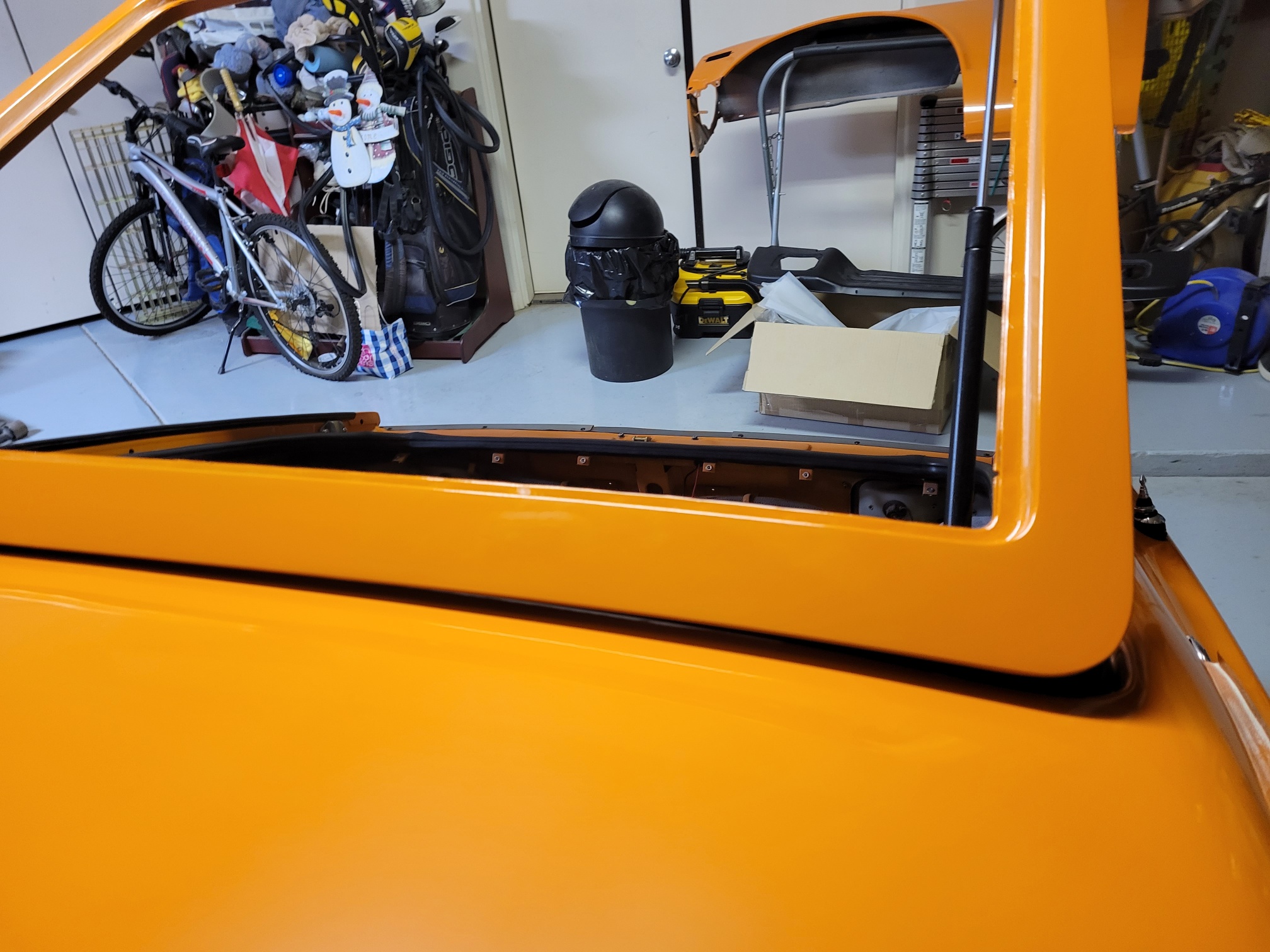
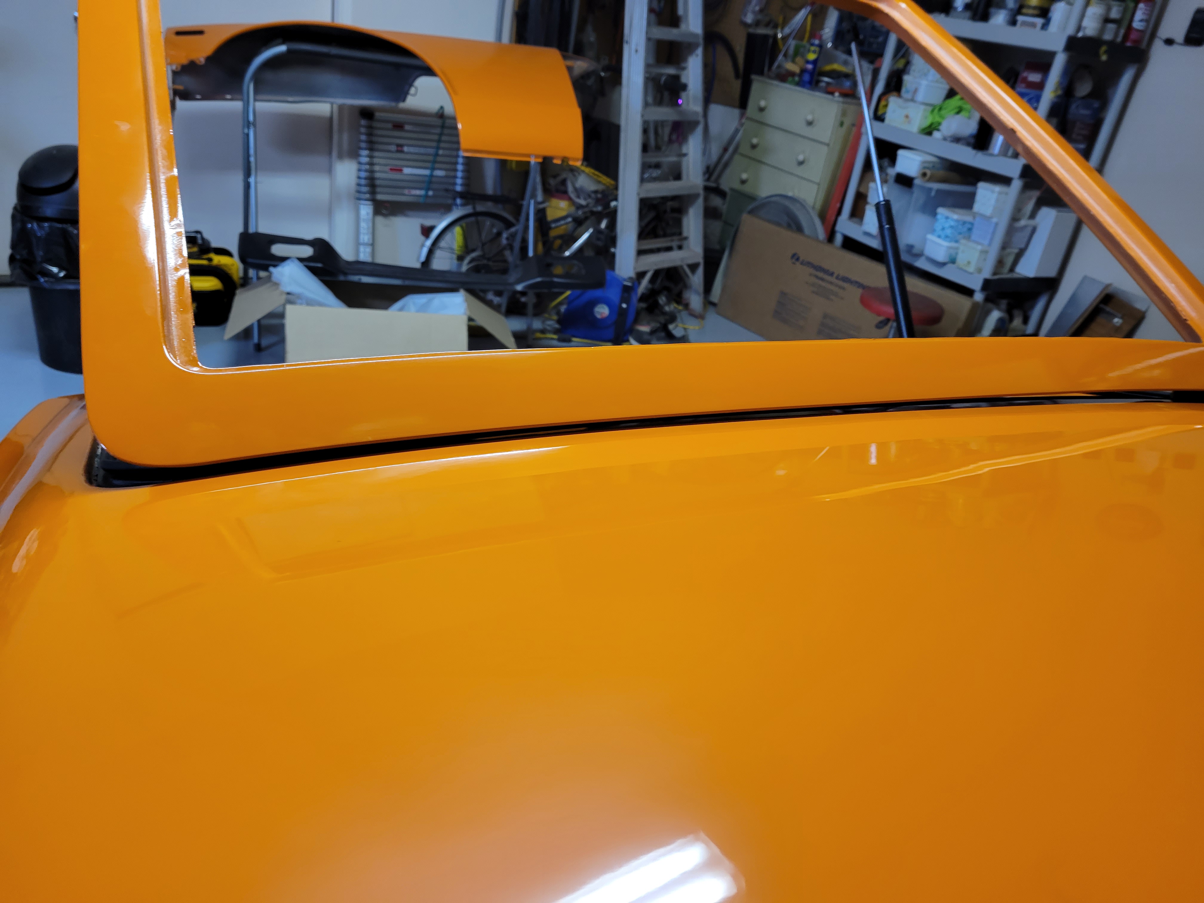
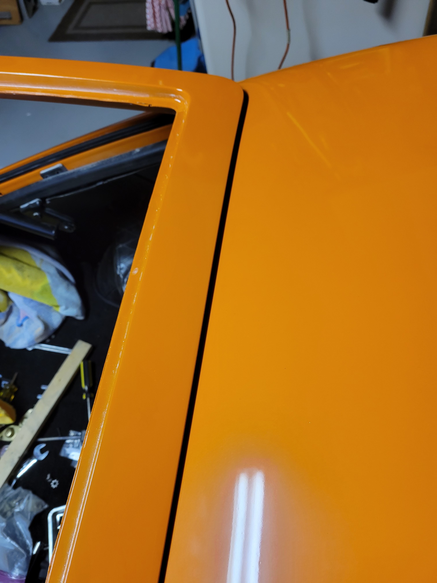
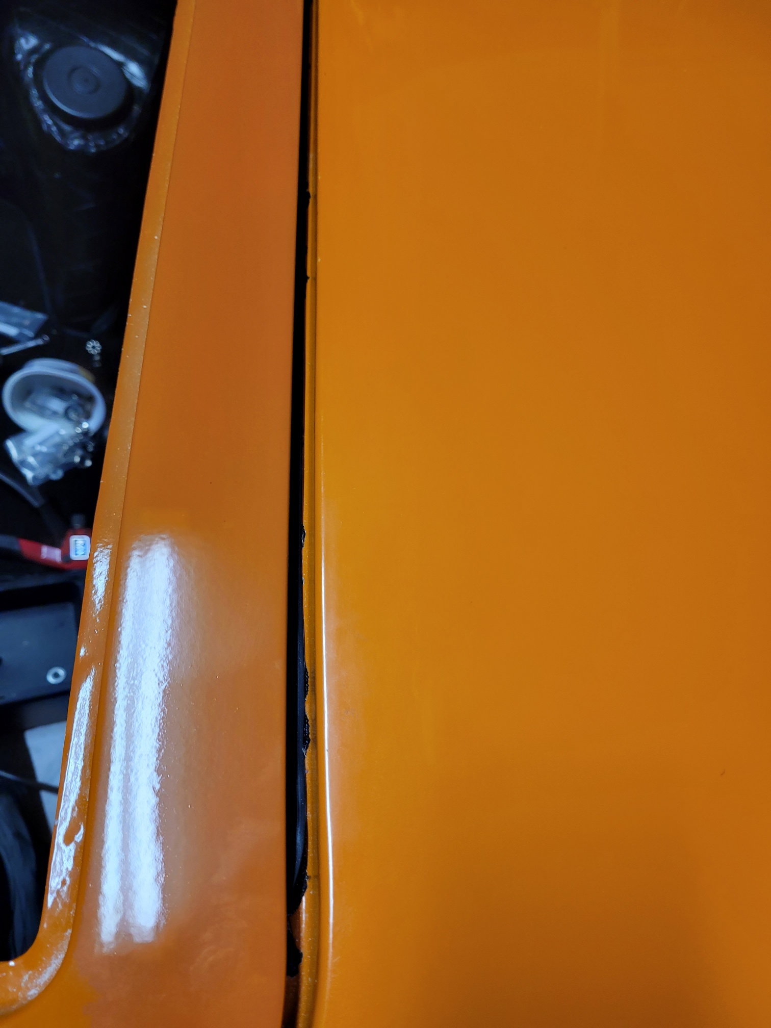
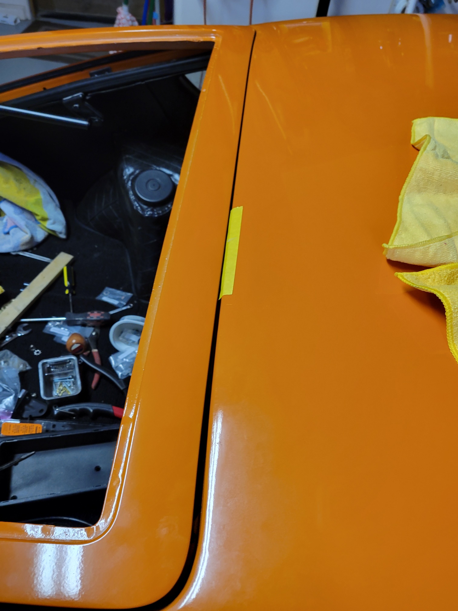
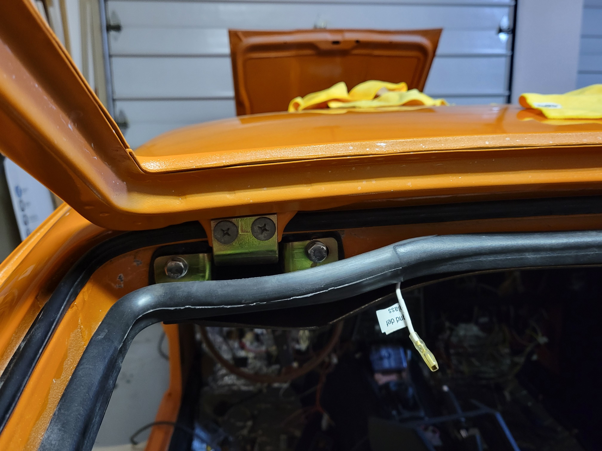
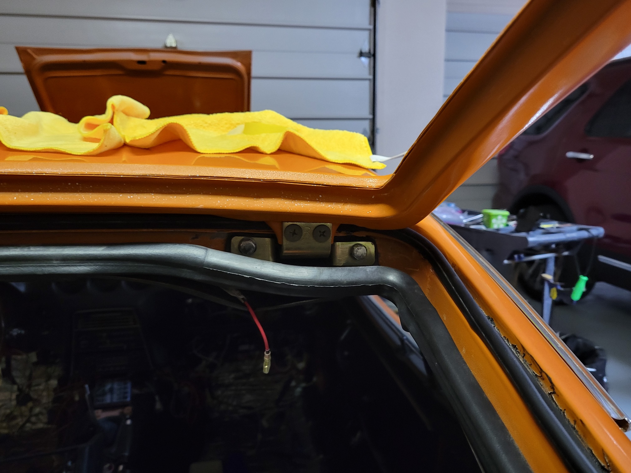
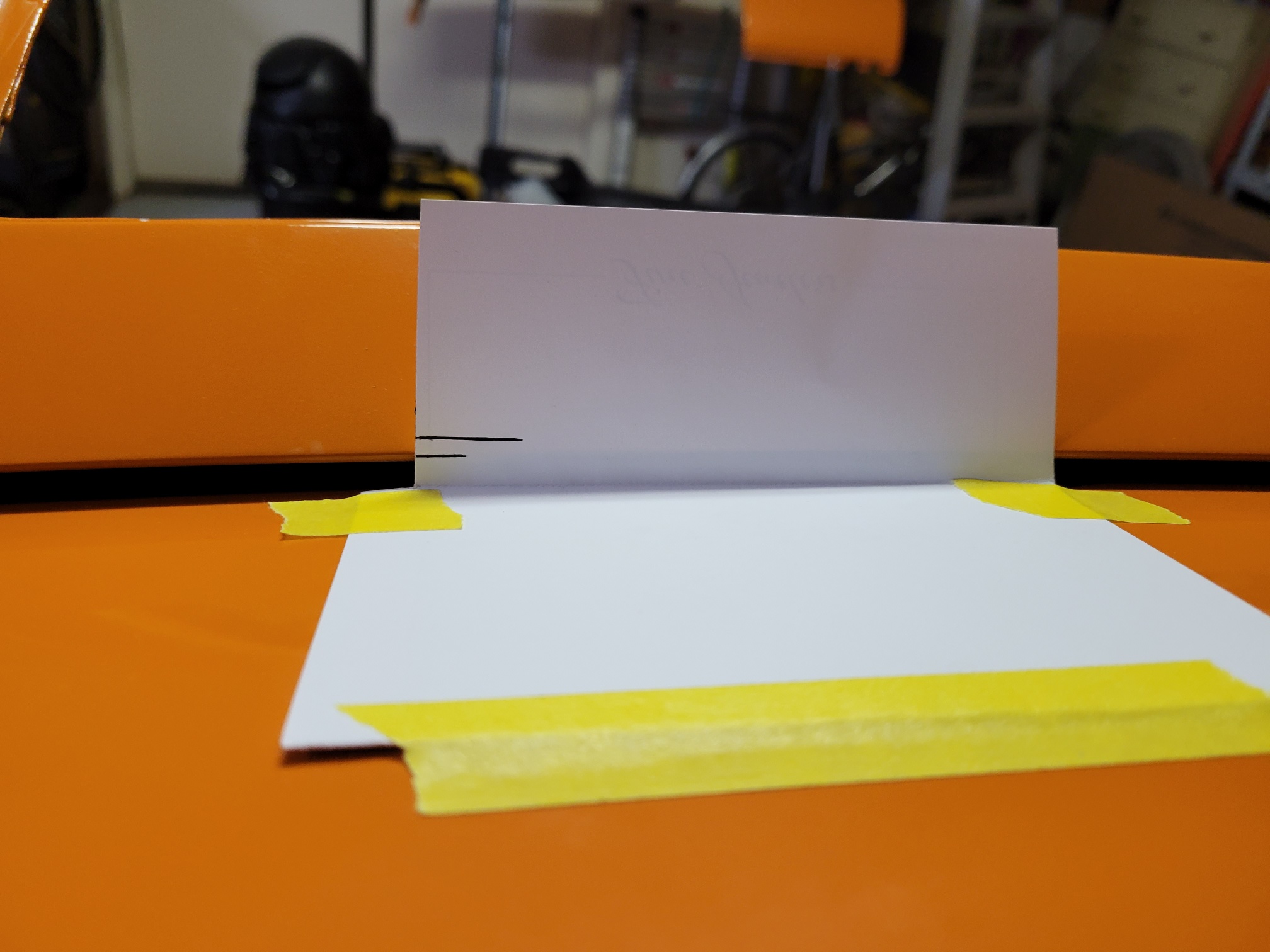
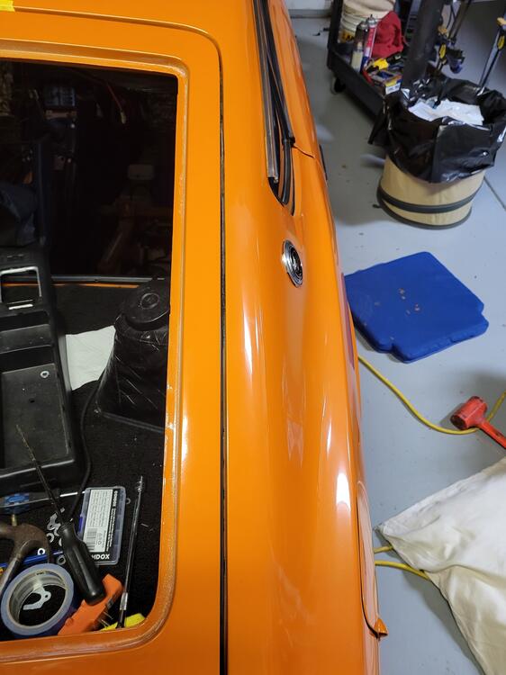
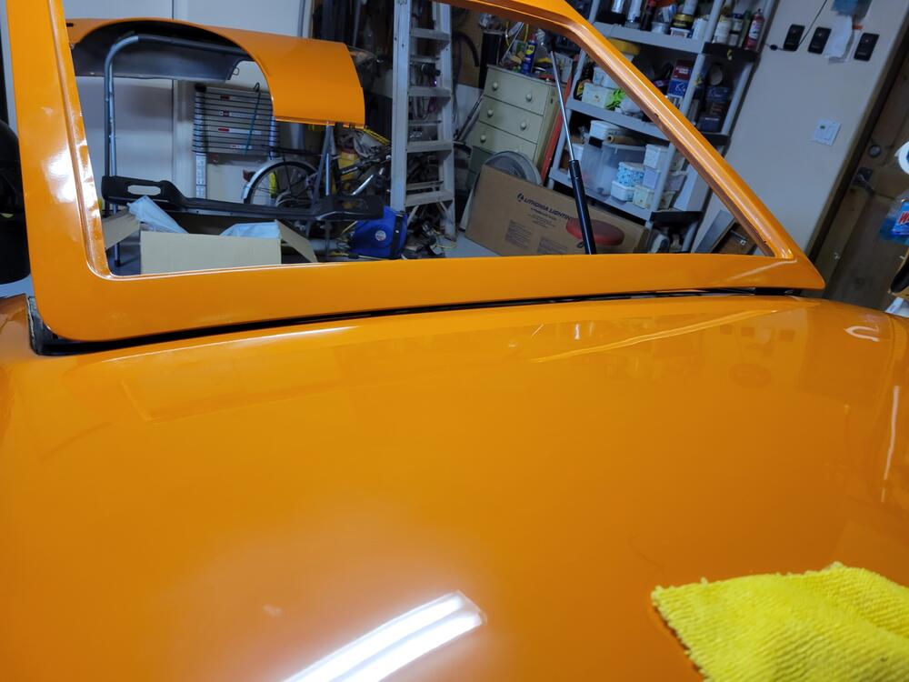
Charles, Good suggestion - thanks for the interest. I took a lot of shots of the hatch, but realized that your starting point and mine may be different. To clarify I am not really concerned at this point with the gaps when the hatch is closed. My first concern is to successfully close the hatch without damaging the paint at the roof line. I did take snaps of the gaps in case I am missing something that they might reveal. I do not have the latch hardware installed so the hatch is not shown fully closed. In this image everything looks fairly good, but as the hatch closes the available space between the roof line and the hatch is reduced to the point where it just barely scrapes the roof, this is the area of concern in the photo that follows later on. So, with the hatch shock absorber installed (on the left side (standard for a 240z) the hatch is pushed upward with enough force to raise the hatch within the hinge. This is actually helpful, I think, on the left side because it creates more clearance to pass over the roof line. Unfortunately it does not affect the right side and so the clearance is less on the right side. You can prove this by lifting the right corner up . It rises approximately 3/16 of an inch, when lifted by hand. The taped area is the concern. This is where the roof line is scraped as you close the hatch. There are no shims installed on either hinge at this point. The image above shows the hatch open all the way. I marked a line (bottom-short line) to indicate the height of the hatch. I lifted the hatch and marked a second line (top-longer) to indicate the height of the hatch when lifted. The difference is about 3/16 of an inch. So, here is my thinking. 1. The shims behind the hinge single bolt head either side of each hinge move the hatch toward the rear of the car and away from the roof line. 2. Shims placed between the phillips head screws and the hatch move the hatch toward the front of the car. 3. The two larger head bolts on either side of each hinge adjust the resting position of the hatch, mostly up and down, and only slightly left or right if at all. 4. Raising the hatch (vertically) when it is in the open position is helpful because it creates clearance to avoid interference with the roof as it is closed. 5. the shock absorber(lift support piston) is stronger enough to lift the hatch vertically. With only one piston on the left side only one side is lifted and the right side is driven downward. The right side can't really move downward because it is at the bottom of the vertical travel of the hinge. Obviously I have no facts to offer as the reason for Nissan adding a 2nd piston to lift the hatch on the 260z and beyond, but since the body of the 260z and the 240z are very similar in this area it seems worthwhile to try adding a 2nd piston to raise the open resting position of the hatch. 6. I was lucky enough to find a pair of 260z hatch lift support brackets and they should be delivered in the near future. 7. While waiting for the 260z brackets I will attempt to align the hatch in minimize the gaps in the closed position Please do not worry about offending me. If you have a better or more elegant solution, or experience that indicates the above thoughts are foolish please advise as soon as possible. I am getting older by the minute and need to get the bucket on the road. Thanks again, to all for your help. regards, ron


-
Thanks to both of you for responding. Charles, The hinges are new, but they have a fair amount of vertical rise. It may not be excessive and I do believe that the hatch may be warped/twisted, so I do not believe that it is the fault of the hinge. With the piston install as possible, but in the middle of the hatch it is just too close to clear the roof. grannyknot, I do not have the long shims but I have used half shims ranging from 1/32 to 6/32 to no avail. the issue is always the same, a couple of 32nds to close to the roof line. When the hatch is closed, with the shims the gap between the top of the hatch and the roof is huge. I know I could bring it in a bit with a shim behind the phillips head screws that hold the hatch to the hinge, but the issue is that I can not clear the roof to close the hatch without scuffing the roof paint. I can't even begin to figure out how to delicately take any warpage out of the hatch and who knows what will happen when the glass goes back into the hatch. regards, ron
-
Thanks for responding. No, I had the piston off, while adjusting.
-
Our project has dragged on way longer than I intended. It is a 1973 240Z that we call "the bucket". The car was completely stripped and has undergone a color change, and there was a fair amount of rust that had to be dealt with, so it should not come as too big a surprise that I am having trouble aligning the hatch. I have new hinges. The 240z had a single (shock absorber) lift support on the left side. The alignment of hatch at the roof line is very close, but I need more clearance to close the hatch without damaging the paint. The problem as I see it is that the hinges have a great deal of vertical play. Because the original design call for a single shock absorber to lift the hatch the left side sits much higher than the right side when the hatch is open. The result is that the hatch is actually tilted down toward the right (passenger) side. I do not have any adjustment left on the right side. Years ago I remember reading that someone added a second shock on the right side to prevent the hatch from twisting. I have since found out that the 260z and 280z both had two lift supports, one on each side. This makes perfect sense to me, given the issue that I am having in that the right side shock absorber will raise the hatch using the play inherent in the hinge. I am hoping that it will give me enough clearance to clear the roof and then the weight of the glass will force the hinge play to be reduced when the hatch is closed. So, my plan is to add a second shock absorber to the right side. In order to do this I need the bracket that attaches to the body that holds the shock absorber. The original shock has a bracket attached to it with a rivet type pin. This end attaches to the hatch. So, If you have experience that indicates that my plan will not work - please share your thoughts, so I can move on to my next plan which I have as yet not thought up. If you a 260z/280z RIGHT side bracket that you want to sell please contact me. I only need the right side bracket, but would buy the whole setup if necessary. The image below is of a left side bracket - I need the mirror image. Thanks for your help.

-
Scott, Thanks, yes, i did get a vintage dash. if memory serves me it was $1k or $1100. It is great. Not a scratch on it. Fit and finish was perfect. Everything lined up perfectly. i don't know what they cost now, but it was worth every penny. Highly recommend. Good luck with your 72 Z.
-
this message is for HappyZ: I have tried to responded to PM, but outlook is claiming that your server is not accepting emails from outlook's server. regards, ron
-
ET14k - thanks - I'm still in the denial phase where I am hoping without reason that there is someway to prevent the scratch. zkars - like I dont have enough anxiety in my life - right? Having said that - I have thought about the drip rail and the fear of taking a rubber mallet to my paint caused me to work on other parts of the project until I uncovered a solution to the cracking paint syndrome. I thought I was in safe territory until I realized that I had to install the rubber window roller which is pinched on to the same door edge and then I figured out that heaven has given me two chances to chip the paint in that spot, once for the roller and then again when I pound the molding on top of it. So how do these guys with the $50k paint jobs do this? There must be someone out there that has conquered this medieval process, OR is this the step just before they put the car up on BAT? Imagine that all these $100k cars with chipped paint lurking under their chrome trim. Next time I buy a car guess where I am going to look, and if there is no cracks then I am going to finally find out how to put the trim back. If I figure out anything remotely promising I will be sure to let you know.
-
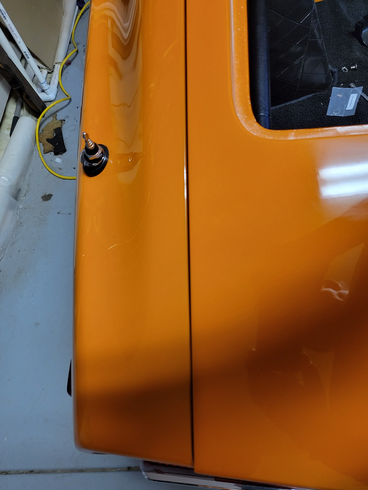
I know here I go again - worrying about chipping paint. I am in the process of putting a door back on our project. The door is mounted and I just finished installing the window regulator and glass. Across the top of the door there is a piece of molding, chrome on one side fuzzy on the side facing the glass. It is press fitted onto the door edge. Is there some method of protecting the paint while installing the molding? Would applying tape to the edge before fitting the molding over it help? Is there a special tool to spread the molding while applying it to the door? Thanks in advance.
-
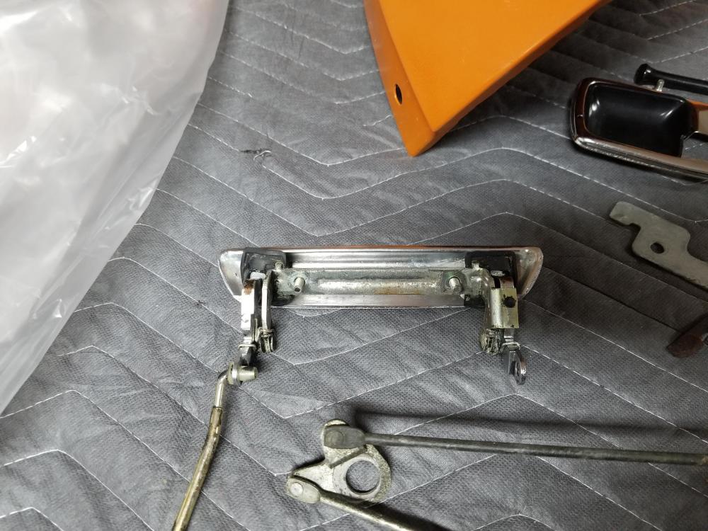
So, I really do not have a horse in this race, and I am on thin ice because I am not trained as a mechanical engineer. To re-state the original issue I was concerned about the bare metal lying between the mounting holes pressing into the painted surface and damaging it, thus potentially allowing water to create an issue. It seems to me that this mini system (the handle, bracket, backing plate, pivots and springs ... etc) is strengthened because the bracket, AND its backing plate behind the door skin sandwich the door skin. My backyard logic would suggest that all the forces involved with lifting the handle are distributed because of the bracket and the backing plate. Again, backyard logic, if you separate the bracket from the skin it seems to me you change the mechanical system and the skin no longer supports the bracket and backing plate in the same manner, and I don't think it improves the distribution of the force involved. So, to me anything that puts air between the skin and the bracket (a washer of any type) may not be favorable. A strip of hard plastic between the door skin and the bracket sounds better than bare metal but will probably injure the softer paint surface. Again, backyard logic, the thin rubber was meant to be sacrificed to protect the paint, and allow the forces at play to remain relatively unchanged, at least in my own mind. The entire bracket surface is still in contact with the door skin. A thin piece of soft plastic might be better than rubber, because it might be more resilient against the elements, but I am not sure that it would fail before the paint. This is a fun topic because it is more complicated than it appears at first glance. If there is an ME or structural engineer out there this would be a good time to explain what is really going on. My final thought, at least for this reply, is that the bucket is 43+ years old. When we acquired it a number of systems had failed, including seals, rusted metal, ... etc. The metal under the door handle was not a problem. I also do not remember anything remarkable about the paint on either door in this area. My point is that without realizing it I may have started a red herring. The Datsun engineers must have done a pretty good job - it lasted this long.
-
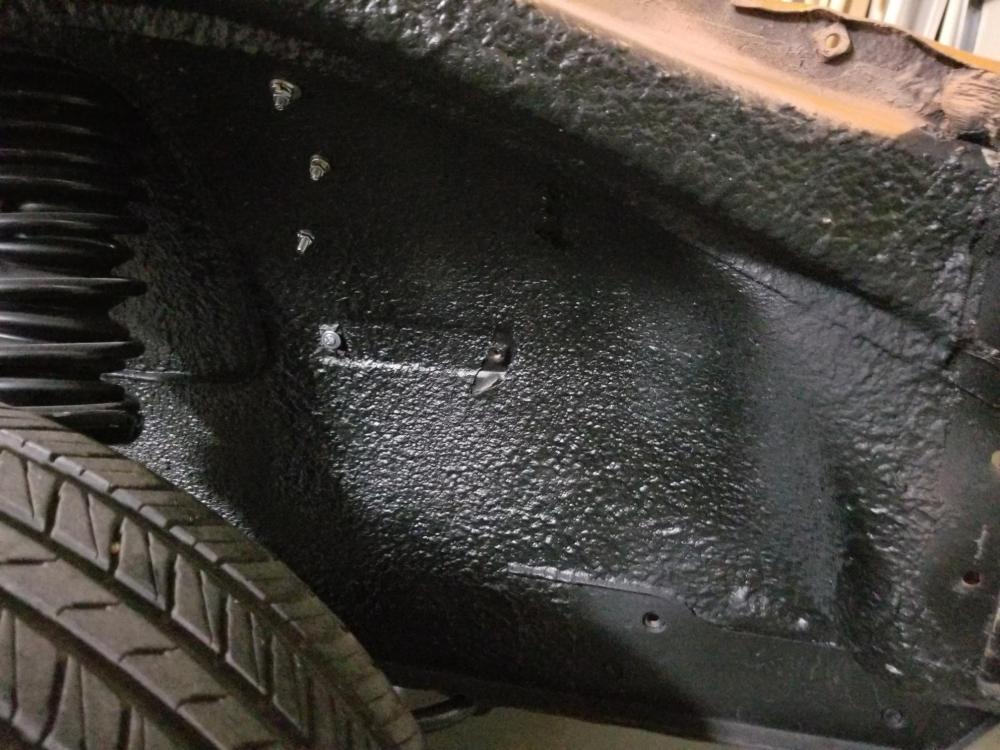
I’m not the most experienced painter, so take that into account when you read this. I am restoring a 1973 240z, changing colors so everything needed to be painted. One thing that I learned is that I am not capable of defining where rust is or is not. I wound up removing undercoating from places that I would have bet would not have rust only to reveal issues that I might have inadvertently covered up if I had not taken the time to remove the original 43 year old covering. I also learned that I could not get away with covering something unless it was completely free of dirt, oil etc. In my case I had to remove fenders anyway and once I started chiseling and using a wire wheel I could not stop. I originally was going to make it body color, but my paint color (orange) is extremely expensive, and I actually liked the blacked out look better. A friend criticized my flat black approach and he was right. I sprayed a rustoleum rubberized undercoating product over the flat black and I like the result. It actually looks better than the picture. The bucket has not gotten back on the road yet so I cant tell you how well it will hold up but it is reasonably thick and seems pretty tough. By the way I would encourage you to take a really good look at what is covering the floors inside the cabin, I had what I believe was a factory coating inside, AND the undercoating on the underside of the car. I found areas where for whatever reason: driving over a curb or a poorly placed jack, or a mean spirited rock chipped the undercoating. I think what happens is that water gets into the crack actually gets between the coating and the metal. Overtime rust is generated and for the most part concealed from most eyes. The dog leg area is notorious as is the floor pans just before the firewall, and of course where the fender meets the lower corner of the door. Free advice probably worth as much.
-
nice to know that I am not the only over-protective wrench in the group. When I removed the door handles I noticed that the bracket had rust on it. There's nothing to prevent it and if it lays on the paint and scratches or chips it could be the perfect opportunity to create a real nightmare. I like putting the rubber over the entire surface of the bracket, drilling holes in the rubber for the studs as that well fill the holes as well. Once again, thanks for responding.
-
I am in the midst of re-assembly of the bucket a 1973 240z. I just mounted a door and started cleaning up parts to be installed on/in it. Here is a picture of the backside of the exterior door handle. There are 2 square rubber seals that are mounted to the handle to prevent water from entering the interior of the door. I would rate mine at about a 6 out of 10. I think I may have found a place to get some but I am not sure that I want to go to the effort of taking the handle mechanism apart to install them. Any tip/experience would be appreciated. Also, as you are aware there is a metal bracket that spans the two square holes in the door. This bracket has two studs which go through the door and provide a means to mount the handle. I spent an unreasonable amount of time on bodywork and painting this car and I must admit I am not excited about butting that bracket up against my fresh paint. There were no signs of a gasket when I removed the handle. I checked with the usual suspects and they don’t list a gasket. Has anyone cut a thin piece of rubber and glued it to the handle before attaching the handle to their door. Again, I would really appreciate any advice that would protect the door.
-
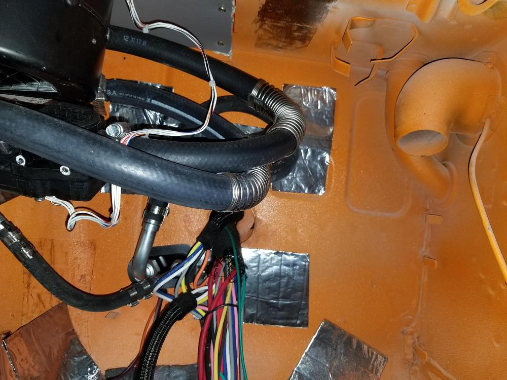
regarding the black mesh - I had used some sound deadner and removed it and that is just residue.
-
mepiazza, regarding the hoses. I purchased them from vintage air. Yes they do mount reasonably well on the oval. The ovals have a raised piece of plastic, just a nub, that catches one or more of the steel re-enforcements in the hose. At the vent end it also mates well. I dont recall how it exactly is fastened but it is fairly obvious once you actually start to work with it.
-
mepiazza, just looked through the thread again and found one of the images that shows the hole that I am speaking about. At the top of the above image is a rectangular silver piece of metal with two for the 4 screws that hold it visible. This covers the hole below the cowl. regards, ron
-
mepiazza, I think you may be confused. The cowl vent that I am speaking about is not part of the vintage air system. It is the hole for the original 240z system. Fresh air entered the heater/defrost system via the cowl. There is a plate /panel between the hood and the windshield. It cover the windshield wiper motor and arms. Air entered the original heater/defrost system via a square/rectangular hole located on the passenger side. It should be visible if you have your dash out. If you dont seal off this hole - air, leaves debris, rain can enter the cabin. My dash is now installed but I can try to get an image of the area if you are unable to spot it on your car. The middle oval outlet on the vintage air system is for your middle vent located in the center of your dash. Regards, ron
-
Thank you Steve, CanTech Z, and Jim. regards, ron
-
Can someone confirm which relay is used for the accessories on a 1973 240z. The wiring diagram that I have been using shows 3 blue wires. The 73 service manual shows the accessory relay harness as a 3 pin harness with 3 blue wires. One of my relays has 3 wires, it is of course bad. Its part number is 25230 89914. Internet search indicates that this is for the intermittent wipers. I have upgraded my wipers and no longer use the original relay. I have a relay available that I believe is part number 25230 89924. I think this is a headlight relay. I probably could use this in place of the accessory relay, it is a 4 pin relay so I might have to jumper one of the coil wires. Power-wise it is probably acceptable. But the real question is can someone confirm the part number and/or spec on the accessory relay? Thanks.
-
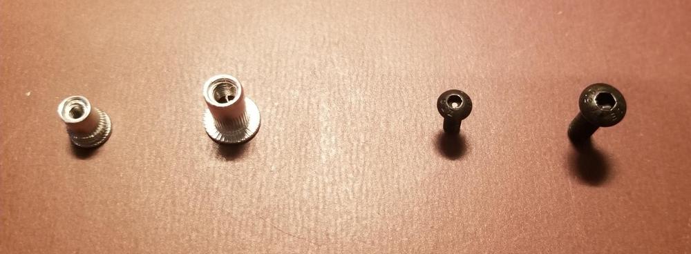
Patcon - As you know 3mm screws are fairly small. Just wanted to let you know that you were right. I could not locate wide enough pan head screws with a phillips head. But screwing a lot of small screws with an allen head wrench, sometimes in the blind, sometimes upside down is not a lot of fun. And the mere thought of doing it more than once drove me to use pan head phillips, still with a washer. Much easier to locate a hole with a magnetic tip phillips screwdriver and fiddle with an allen head. Thanks.
- 11 replies
-
- 2
-

-
- blind nuts
- fasteners
- (and 2 more)
-
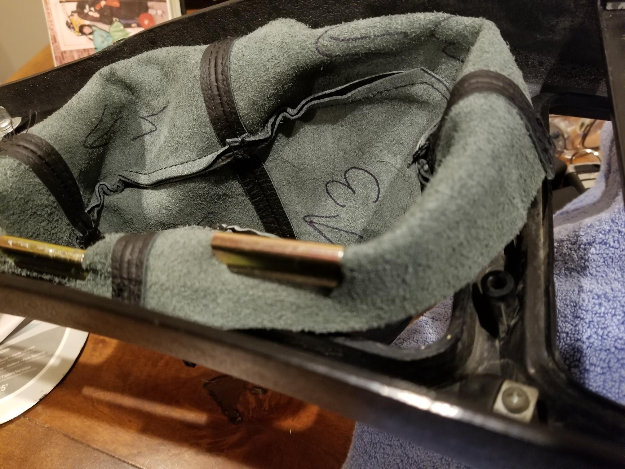
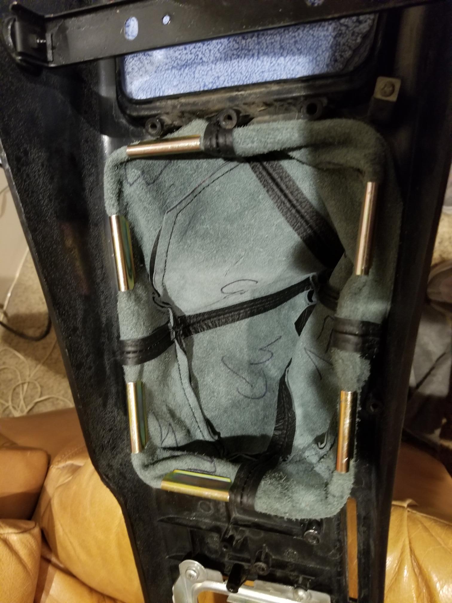
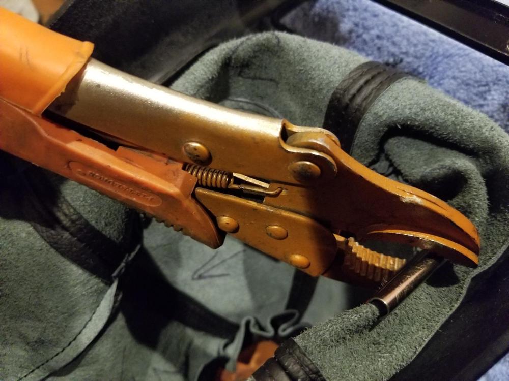
Replacement of the Inner and outer Shift boot When I bought the bucket it did not have an inner or an outer shift boot. Replacing the inner shift boot is fairly obvious. There is a rectangular ring that surrounds the boot and holds it in place. The outer boot is soft vinyl, or leather and it slips over the gear stick. Mistake 1: I installed the center console after completing work on the center console area and everything that is involved with that like the vinyl over the trans. tunnel, choke control, fuse box lid, indicators, radio etc. It turns out to install the outer shift boot you must remove the center console so that you can press the spring clips onto the underside of the center console, seems obvious now, and it would be exceptionally obvious if I had removed the previous outer shift boot. I did not think this was going to be a particularly difficult task. I recall seeing someone hammer the clips into place to hold the boot to the backside lip of the boot hole in the center console. This proved to be way too scary for me. My center console is in pretty good shape but I suspect it is 40+ year old plastic. The new leather boot is thick and the new clips are very tight. One blow with the mallet and I put the bludgeon down and started typing. There must be a secret that I was unaware of and if I find the decoder ring or learn the secret hand shake the leather boot will be installed on the clips, it will be tight, the center console WILL NOT crack and this minor nightmare will be over. Unfortunately, a search of the forum and the internet did not provide much in the way of guidance or tips. So this post is NOT for those of you that have been successful in the past and did not think it would be valuable to document the process because it was such an easy project. I was not having much luck draping the material over the console and hammering or squeezing the clip over the boot onto the console. It seems insignificant and it may be so, but putting the leather inside the clip and then putting the clip on top of the edge of the console made a big difference, for me. It took me a while but it finally came to me. Hammering was too scary, pushing the clip into place seemed impossible. So I went to my second most popular GOTO tool. The first being the mallet and the second being a pair of vise grips. I slowly and carefully squeezed the clip over the console lip. It was easy. I cant explain why it took me so long to figure it out. Now that it is completed my memory of the task was that it was easy. I feel a bit silly posting this, but hopefully the next person to replace their outer shift boot will not have to think twice about how to go about it. One more thing. I read that you only need 6 clips. In my opinion you would be better off with eight. There is no way to get a clip over the seam and if you did the clip would be expanded to the point that I doubt it would hold very well. Below are some photos that may be useful . By the way the console did not crack -----yet!


-
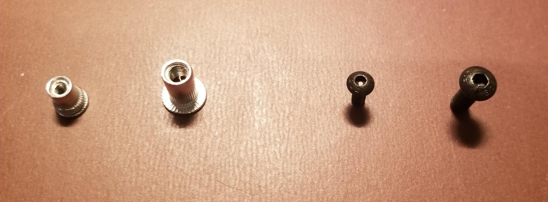
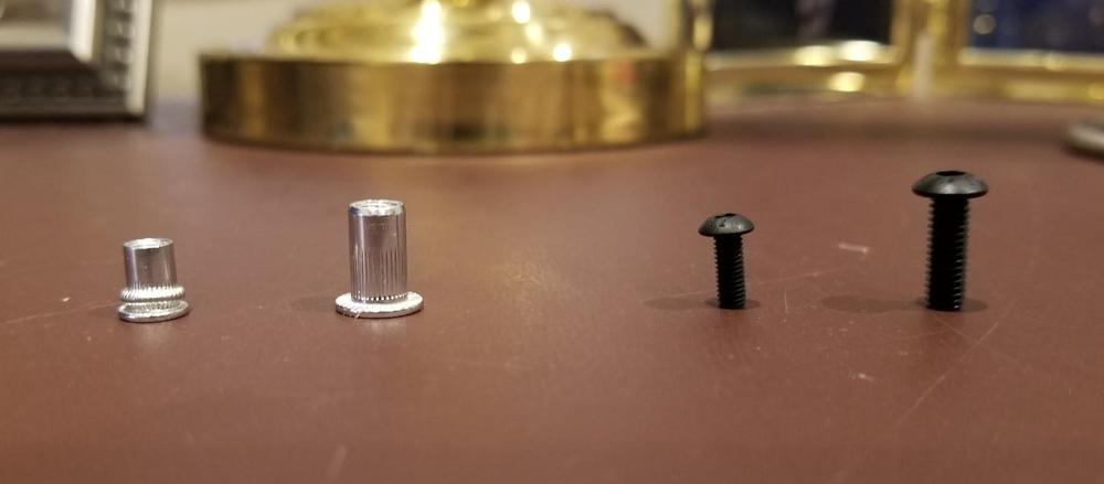
Patcon - Great question. I am using a button head screw, with an allen head that has a black oxide finish. Above right to left is a 4mm button head, and a 3mm button head I thought the button head with an allen head would be the least conspicuous. As you can see the 3mm screw is quite small. A phillips head would be easier to install/remove, but I thought it would be more noticeable. Unfortunately the 3mm head is too small for the hole in the plastic panel so I am also using a flat washer with a black oxide finish. I would be very interested if you have any other suggestions. Also for anyone that is interested on the left side of the images above is an aluminum riv-nut. In the center is a new (unmolested) 3mm rivnut. On the left is a 3mm riv-nut after an install attempt. You can see that it is crushed on the knurled portion of the riv-nut between its collar and its threads. One more thing that might be of interest. There isn't a great deal of room between the plastic panels and the car body. Having said that I am in the process of trying to fit some sound deadner between the two. Where possible I am going to try to put some thermal insulation. Can't do much because I am concerned about damaging the plastic panel if there is too much stress due to the increased depth required by the insulation. If someone has tried this please let me know if it is worth the effort - thanks.
- 11 replies
-
- 1
-
-
- blind nuts
- fasteners
- (and 2 more)
-
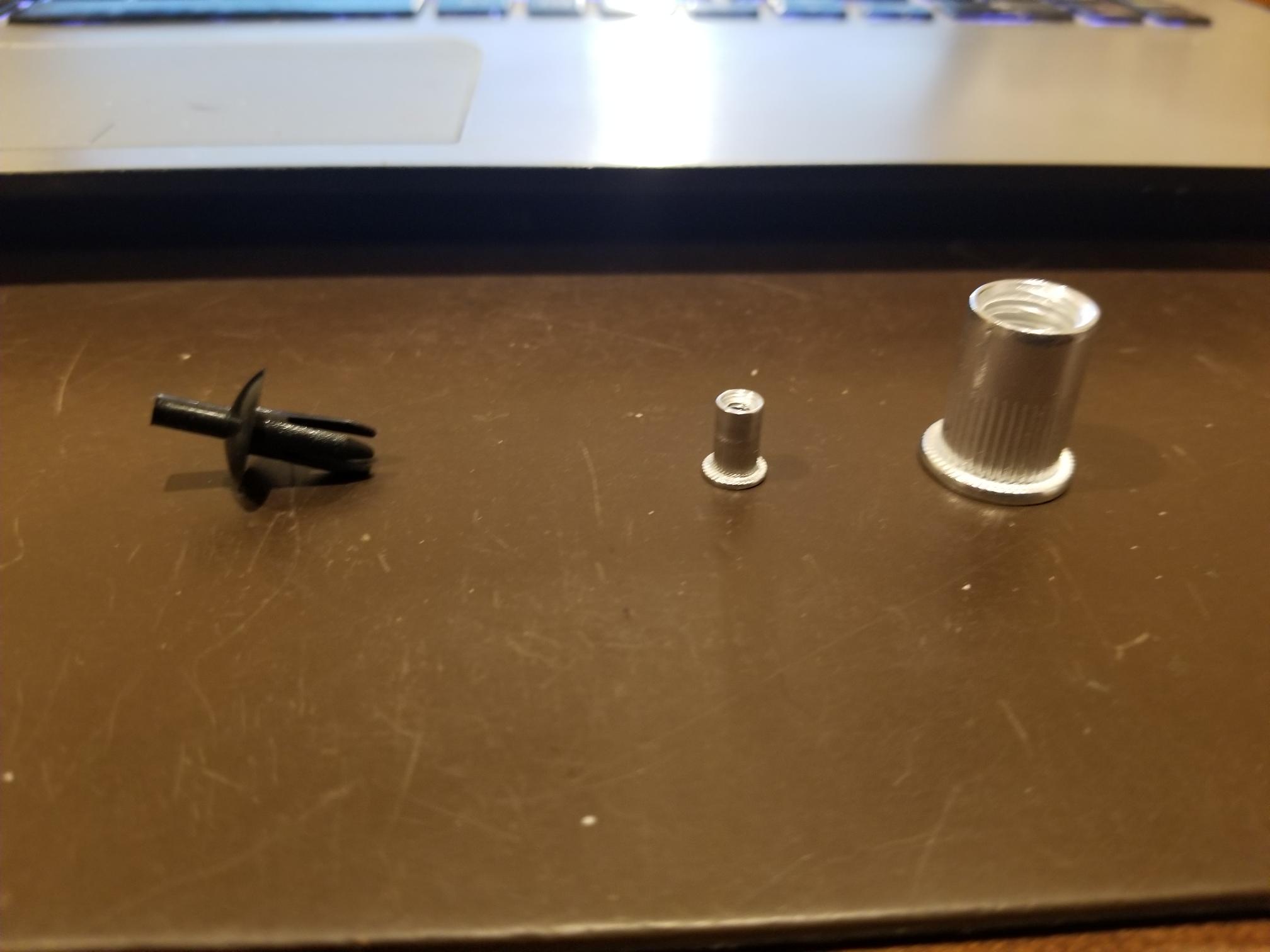
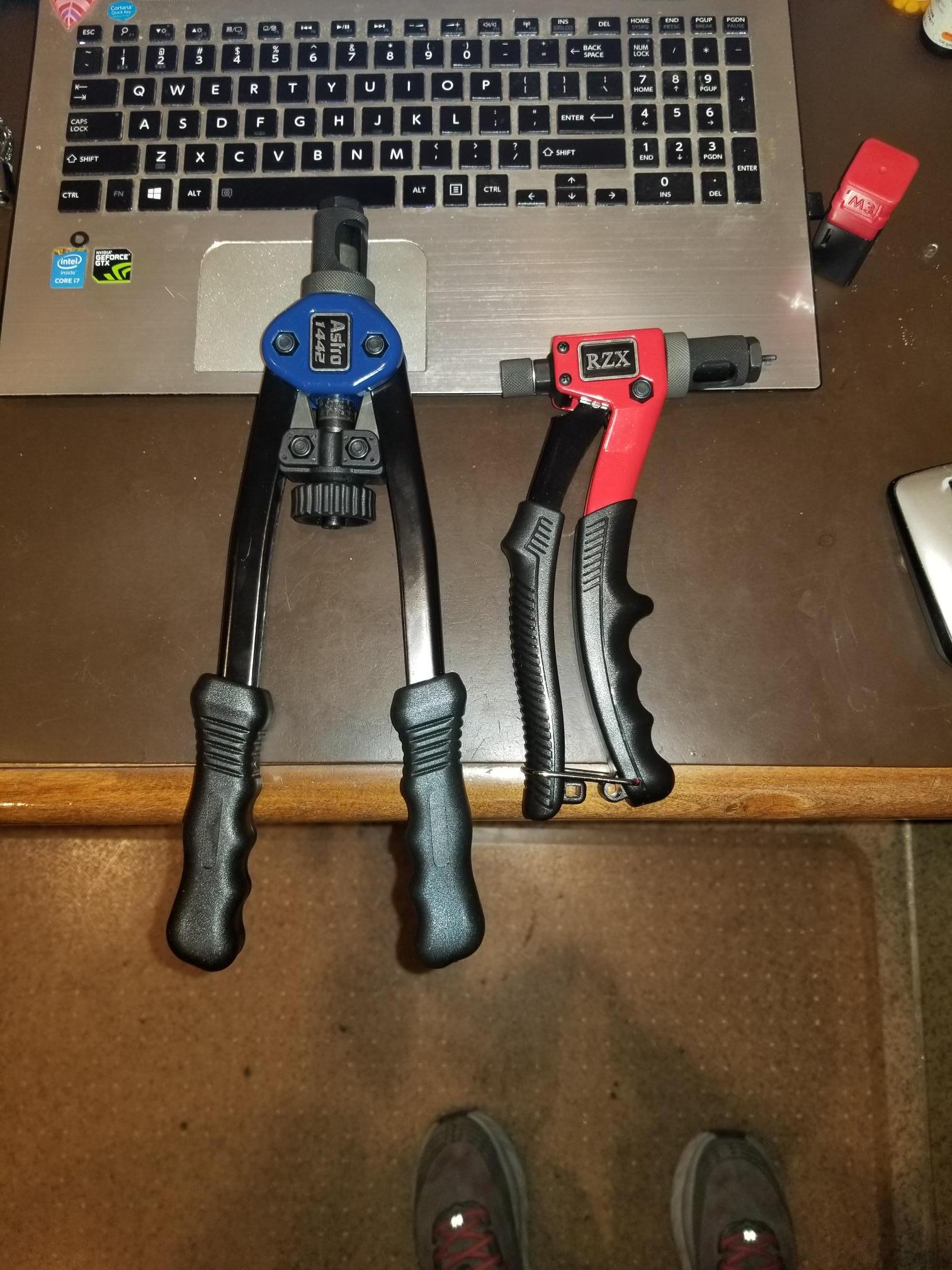
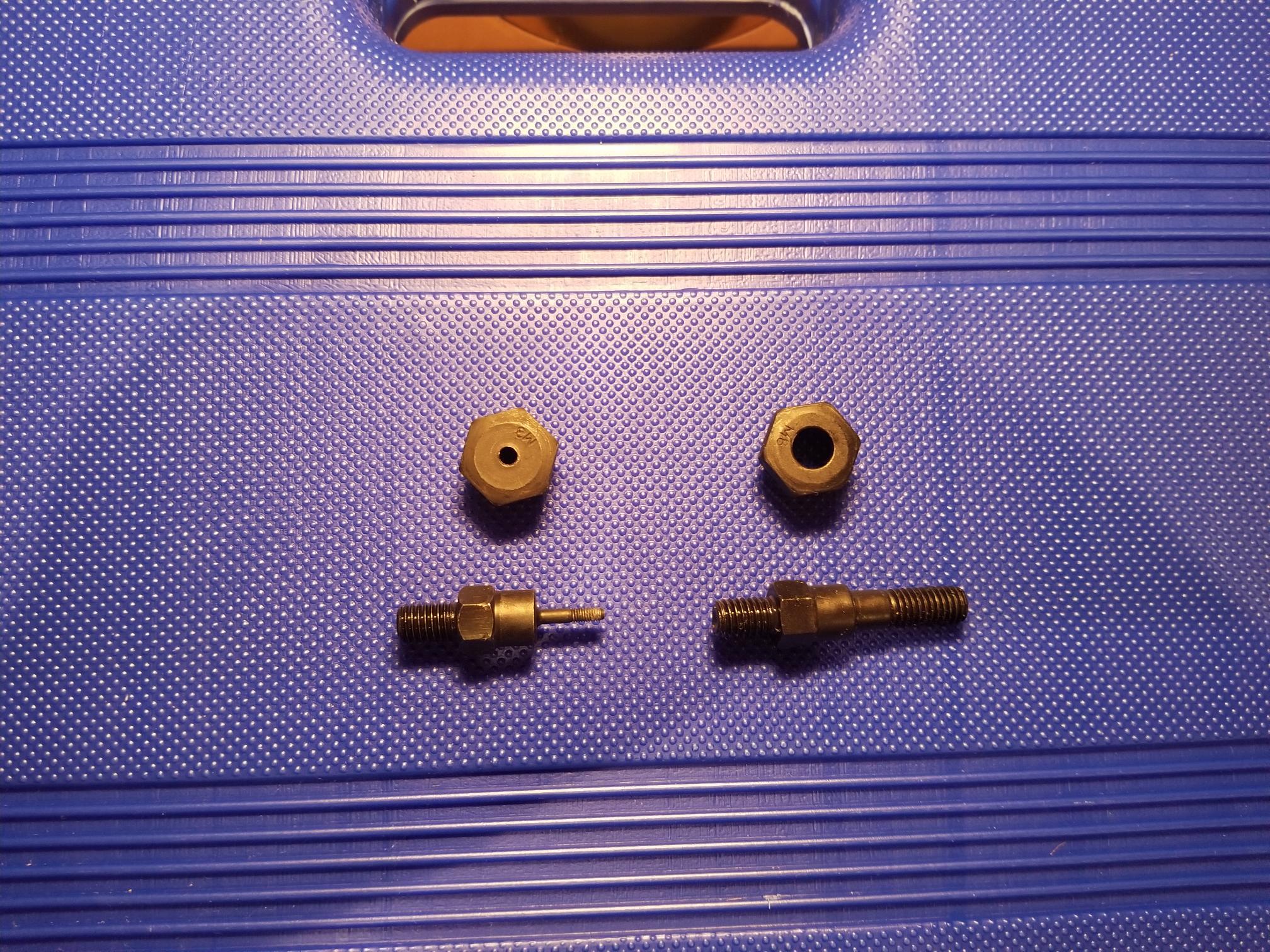
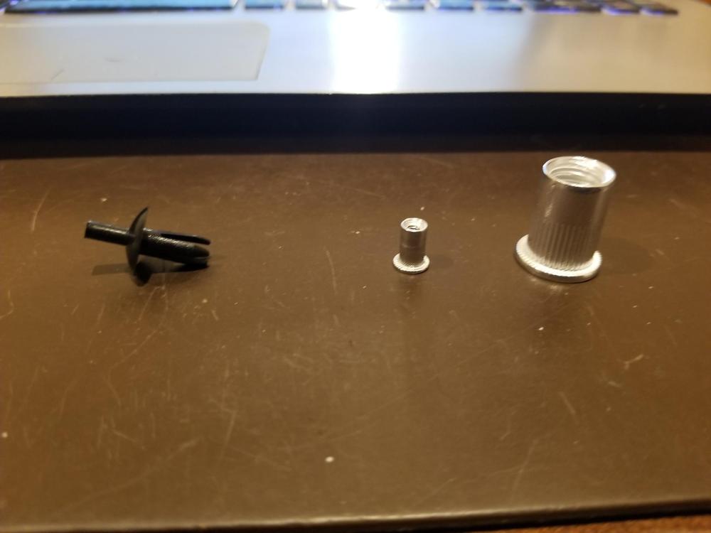
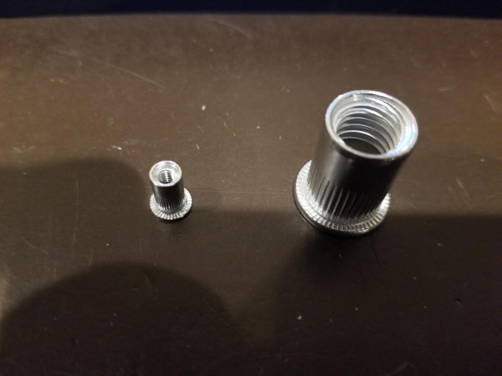
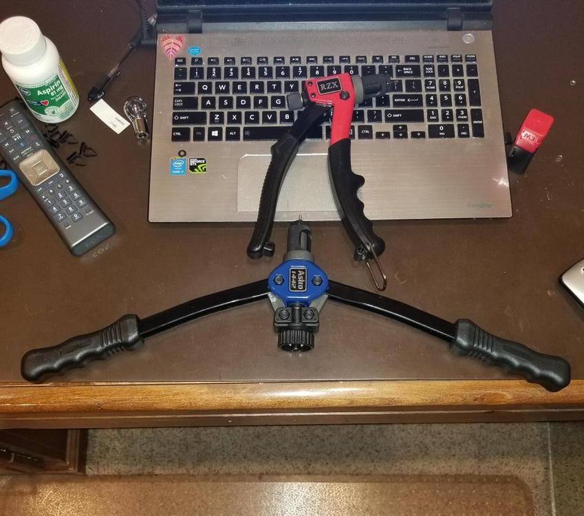
I am in the process of installing the bucket’s interior. Often times I find that parts need to installed, removed, adjusted/repaired and then re-installed. A while back I bought plastic rivets for interior. Two sizes are required. The taillight panel requires 8. I believe they are $3.00 each. The interior plastic requires approximately 40. These are larger and come in bags of 10 at approximately $7.00 a bag. I don’t think that they are available at your local hardware store so there is shipping cost and worst of all for me time delay. So, the cost of these plastic rivets is annoyingly expensive (approximately $50+) considering it is just a fastener. These rivets are neat but in my opinion there are a few issues. To remove one you poke the plastic inset pin through the rivet. In a blind situation the pin goes into the bowels of the chassis never to be found. Without the center pin the rivet is useless so it is a throw away. Some suggest using a nail, or a cotter pin or something else. If I did, I would have a bunch of these alternatives rusting away and clinking and clattering away somewhere within the bucket. A bit of this is tongue in cheek – but mostly not. The second issue is that these plastic rivets cannot be tightened. Oddly enough on some of the plastic panels one of the fasteners is an actual 4mm screw. I think they did this because – they could. The material the panel was being attached to was thick enough to accept threads. Where the plastic panels attach to the remainder of the body the material is too thin to accept a thread so they used the plastic rivet. In addition to the single use aspect of the plastic rivet the panels wind up becoming loose or squeaking especially after 40+ years. I recently stumbled across a post discussing “internal rivets”. ZCARS (forum member) offered an alternative called a Riv-Nut. I was not aware of this device, but became intrigued with the solution. I suppose most of you have experience with this, so this might be a bit boring, but for the uninitiated I hope this will help you in the future. I am a novice when it comes to the use of this device or the install process. These are my opinions and experiences, and should not be considered the end all. If there are errors – they are not intentional and I would appreciate your corrections/improvements. Riv-Nut goes by a number of other names: Rivet nut, nutsert, blind nut. It is installed in a fashion similar to a common rivet. It’s purpose is to provide a means of creating the equivalent of threads for a screw in thin metal, and it additionally works when you cannot get behind the material, for example in the middle of a panel where there is no access to the backside. I could have used this countless times in the past. Often times this problem is solved with a nut that is tac welded to the back of the material. This does not work well for the DIYer. Many have no experience or equipment to weld, sometimes you cant get to the back of an area, and in some cases the material does not accommodate a welding solution. Of course, I have used sheet metal screws in the past. I hate screwing anything with a point on it into a blind area, and sheet metal screws do not like to be unscrewed and refastened many times. There is a fastener I don’t recall its name but you slide it over the edge of a hole. It creates the equivalent of a thread to hold a sheet metal screw. I have even used something similar with a captured nut embedded for a screw. This however only works at an edge. The Riv-nut is, in my opinion, an elegant solution – Thank you ZCARS. Here is a photo of a plastic rivet (on the left, and riv-nuts on the right #3, #10 Above image you can see the threads inside the riv-nut .How it works - The tool has a main body with some sort of handle or arms to apply pressure. There is a part called a mandrel which attaches to the tool. The mandrel is specific to the size of the Riv-Nut involved. The size of the hole is not the same size as the bolt or screw to be installed. Install the mandrel on the main body of the tool. The end of the mandrel that is exposed is threaded. Inside the riv-nut are threads. You screw the riv-nut onto the mandrel. Next you put the riv-nut through the material (just like a common rivet). While holding the riv-nut in place in the hole you apply pressure by squeezing the handle. Different tools have different handles. To provide more leverage, necessary for larger bolts, some tools have longer arms and require two handed operation. Other tools look like a common rivet gun and operate using a single hand. At much higher cost there are air powered versions, some attach to a drill others use just a mandrel and two wrenches. All of them have some sort of mechanism that applies pressure to the mandrel threaded end and withdraws the mandrel from the material which causes outward force, which then collapses the outer part of the riv-nut trapping the material. Obviously the portion of the riv-nut that collapses cannot be associated with the threads in the riv-nut. If you look at the outside of the riv-nut there is a collar which rests against the outside of the material that you are attaching to the riv-nut. There is a knurled portion of the riv-nut next to the collar. The threads of the riv-nut begin where the knurled portion stops. The knurled area is the part of the riv-nut that collapses against the blindside (backside) of the material. You then unscrew the mandrel from the riv-nut. There is a bit of technique involved which is gained through experience. You don’t snap the riv-nut like a common rivet. Recall that the tool is threaded on to the riv-nut. You need those threads in tact. If the riv-nut snaps it is because one of two things has happened. Either the threads on the riv-nut have given way or the threads on the mandrel have given way. So, you only want to collapse the riv-nut enough to grab the material surrounding it. Now there are different types of riv-nuts: aluminum and steel for example. Using a 3mm mandrel is a fairly delicate operation. I used aluminum riv-nuts. I thought that I would rather have the riv-nut break rather than the mandrel. Also, since I was only attaching light plastic panels the amount of holding force required was minimal. The main difference between aluminum and steel riv-nuts is holding force. So, the material of the riv-nut and the size of the riv-nut affect the holding power. When a riv-nut is destroyed during installation you need to remove it by drilling it out. When an aluminum riv-nut fails you can see the remnants of the threads on the mandrel. They need to be removed. There are a number of very good videos and printed descriptions that will do a far better job of describing the process then this post, but I thought this might get you interested enough to consider this solution. There are a number of different tools to install riv-nuts. They come in different sizes and shapes and of course at a range of price points, from $15 to many hundreds of dollars. My research led me to buy an astro-pneumatic 1442. It costs around $90. It has many very good reviews. It will accommodate a number of different size fasteners including metric (#5- #8) and a number of SAE screw sizes. I believe this is a great long term choice for me. Having said that Astro-Pneumatic does not offer a #3 or a #4 mandrel. I called Astro and they confirmed that they do not offer smaller mandrels. Most of the holes involved for these plastic panels are 5mm (diameter). This requires a 3mm riv-nut. Turns out most of the more robust tools do not offer a 3mm option. You could drill the holes to accept a larger diameter fastener, I wanted to leave myself the option of going back to plastic rivets if necessary so I decided to invest in a second tool. The 1442 requires two hands. It is medium size 13 inch handles. The handles open wide to give you more leverage. Some of the places that you will want to install a 3mm riv-nut require a tool with a smaller profile. A smaller tool will cost between $15-$30 approximately. In fact if you are using aluminum riv-nuts that are small, then a small profile, inexpensive tool might be the smart choice. Now here is an interesting data point. It turns out that #3 and #4 mandrels that are part of some less expensive sets actually fit the astro 1442. I actually bought a cheaper kit and used its mandrels on the astro 1442. So, in retrospect I would still buy the astro 1442 – it works very well, and it appears to be quite robust. I think it handles small and large riv-nuts in aluminum or steel very well. I would then enhance its capability by purchasing a #3 and a #4 mandrel. The smaller, one handed tool, is not a necessity, but I think it will help in tight places. I think it will probably have a shorter lifespan, but I do not think that it will be utilized as often as the astro. 13 inch Astro 1442 (Left), RZX 8 inch (Right) both are in their closed position Above: Astro 1442 and RZX in Open position #3 mandrel (left), #8 mandrel (right) Update 8/31/20 So it has only been a short while but I have installed a number of RiV-Nuts. Most of them were 3mm and the remainder were 4mm. All were Aluminum. I can not comment on the performance of these tools using steel rivets. I was very impressed with the performance of BOTH tools ( the Astro-Pneumatic 1442 ANd the RZX. The RZX single handed tool worked much better than I exppected it would. Some of the nut-serts have to be installed in the hatch area with the tool facing the sky. Using a 2 handed tool would have been impossible there just isn't enough room, but the RZX performed excellently. With the 1442 and a 3mm nut-sert some experience is required to know har far to close the handles. Too much pressure and you snap the aluminum insert. The RZX reliably worked when closing the hand grip all the way. As I said I have no experience with the RZX and steel Riv-Nuts, but I believe both tools are good additions to my tool set.


- 11 replies
-
- 2
-
-
- blind nuts
- fasteners
- (and 2 more)
-
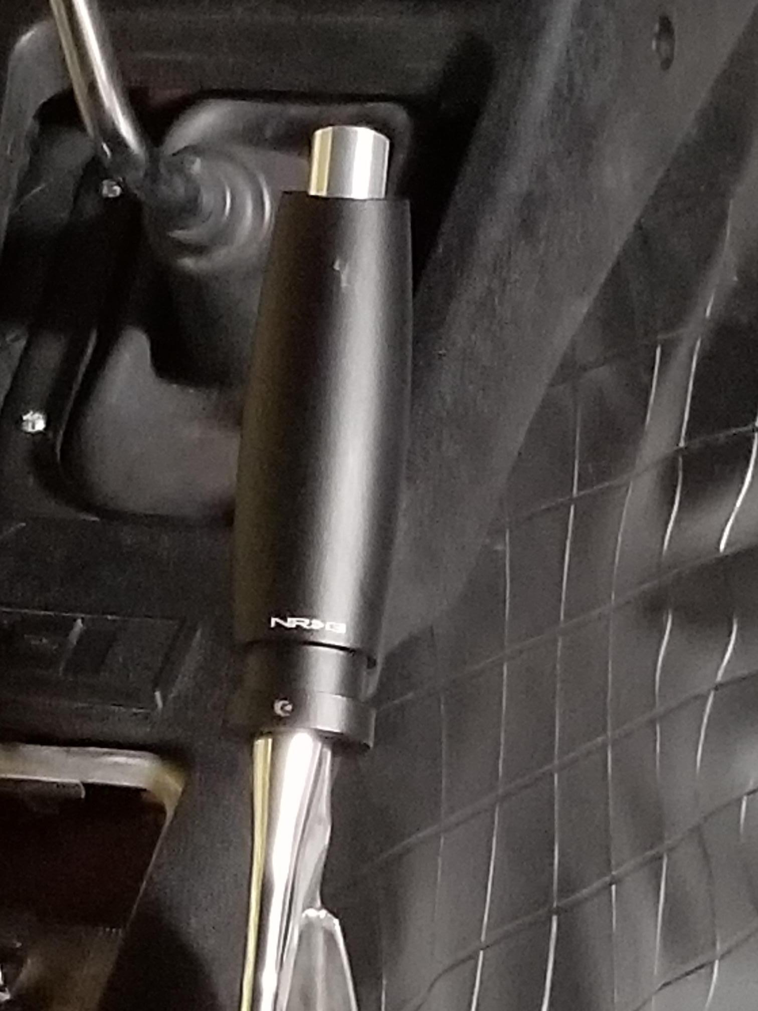
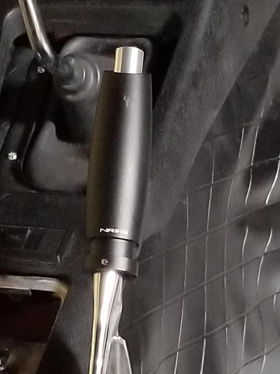
Report post ID: #8 Posted 16 minutes ago (edited) Was this tough to install? Not at all. You will want to clean up the metal handle to your satisfaction. Having done that, It merely slides over the original metal and you tighten a set screw (which you can actually see in the picture, at the base of the handle - mid-image).
-
My handle crumbled in my hand as I was installing it after repairing the mechanism. I looked high and low and could not find just the plastic handle. For me buying an entire original mechanism did not seem wise as there is no way to judge how long it would last. ABS appears to have a useful life, but I fear we are getting to the point where we are testing the limit. I found the one in the image below, but I forget where I got it. The brand is NRG. I like the way it looks but if you are a purist it will not do.