qz16
-
Posts
147 -
Joined
-
Last visited
-
Days Won
2
Content Type
Profiles
Knowledge Base
Zcar Wiki
Forums
Gallery
Events
Downloads
Store
Blogs
Collections
Classifieds
Everything posted by qz16
-
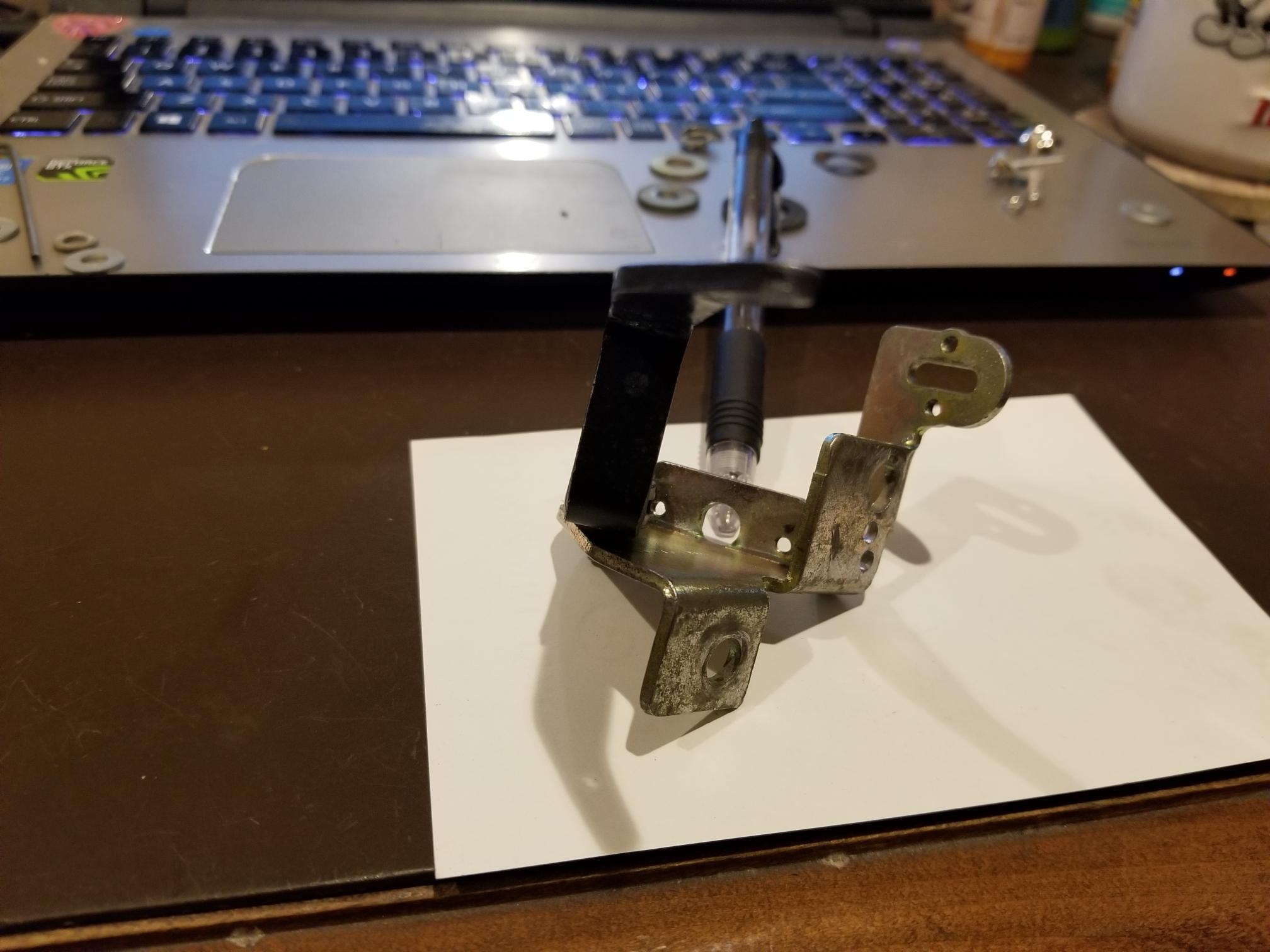
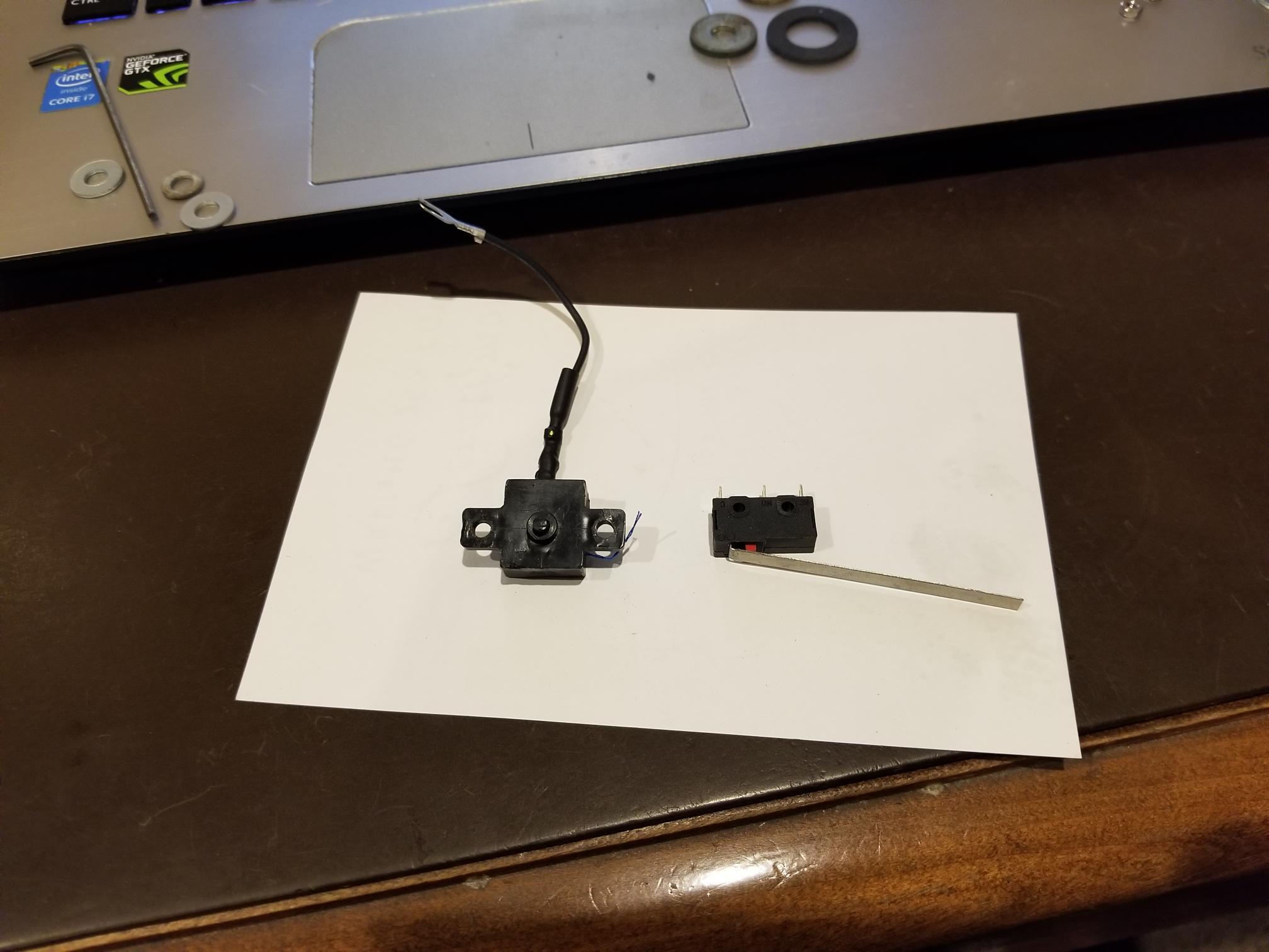
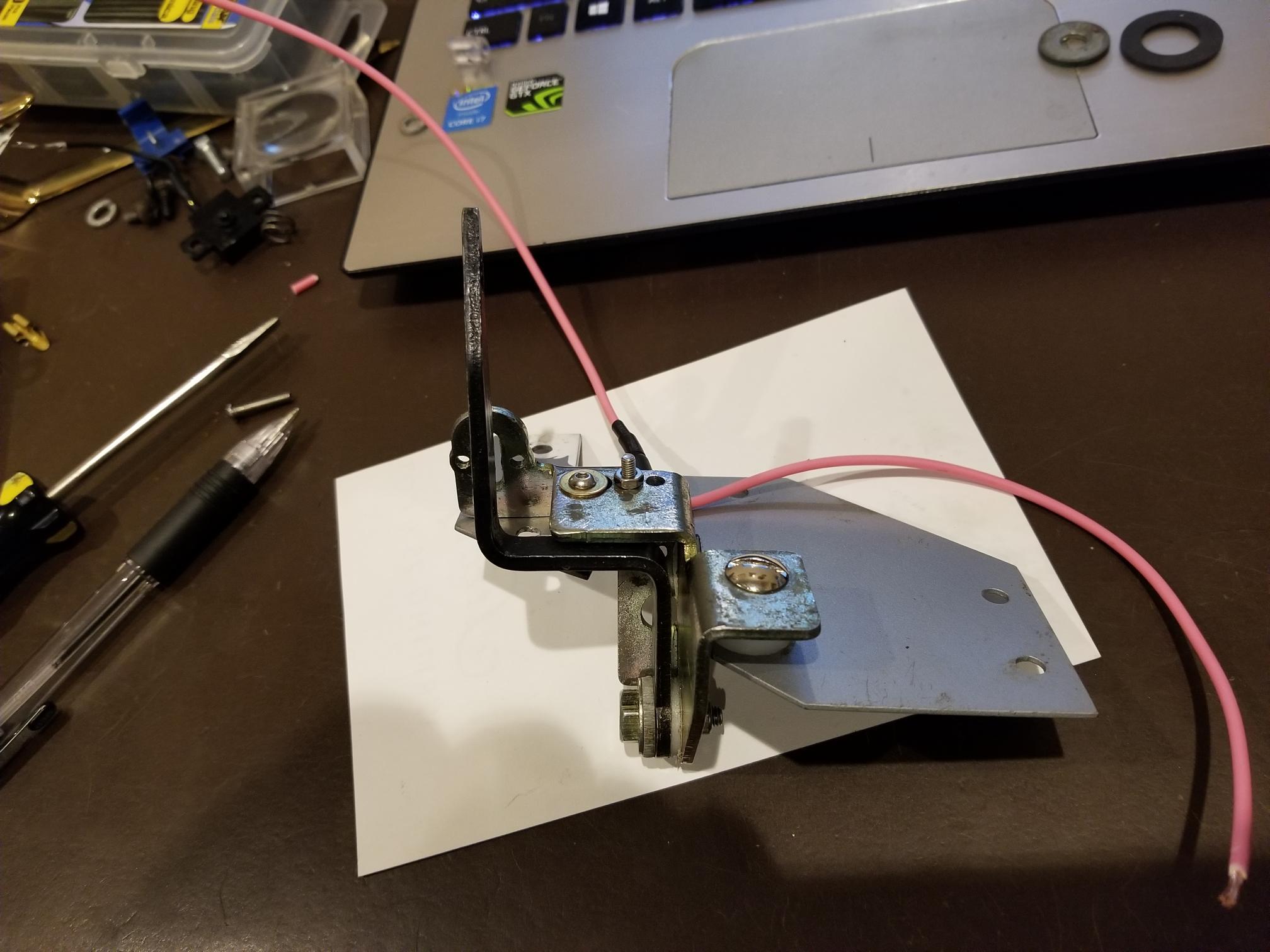
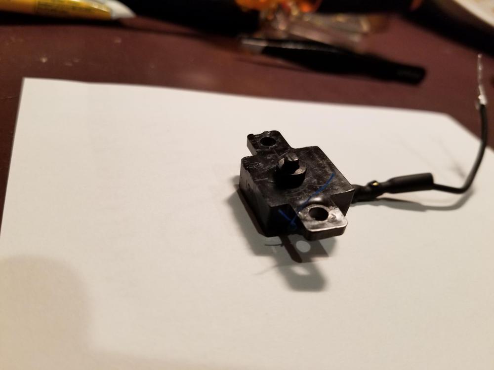
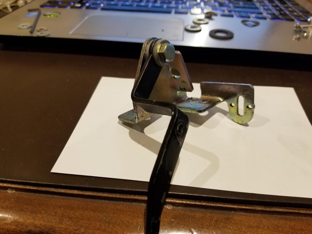
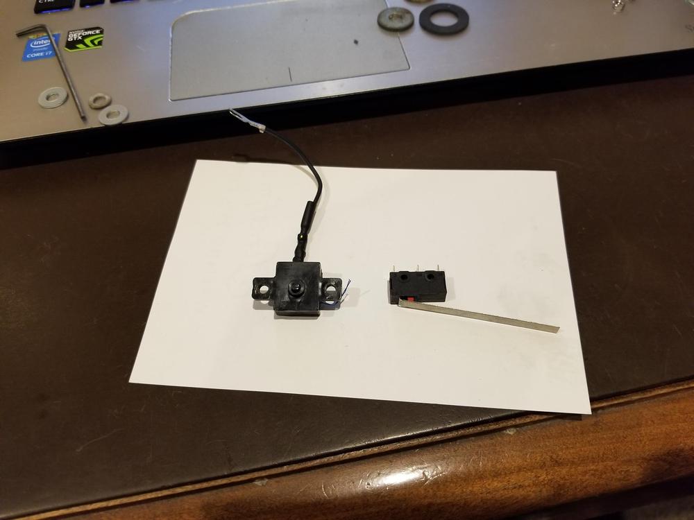
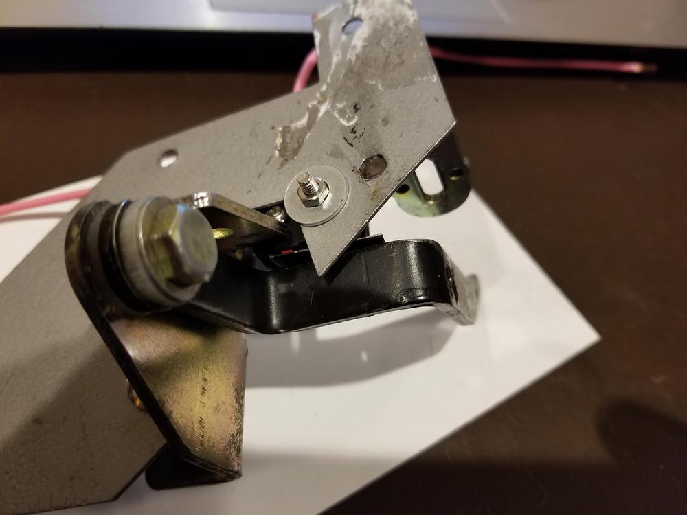
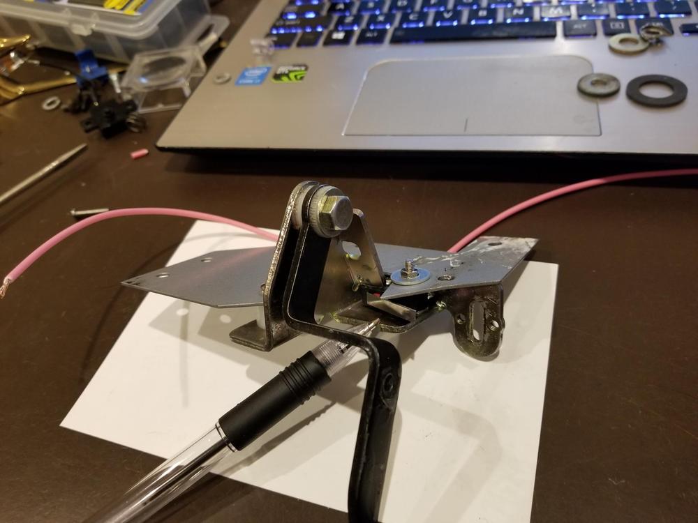
preface: I am working on the restoration of a 73 240z. A mentor of mine used to say “The enemy of good is better”. I adopted this saying but often times I unfortunately ignore it. Our car “the bucket” has what I believe is its original center console. It has a single slot on the driver’s side for the choke control. At some time in the past the original choke control arm and bracket were replaced with a generic pull out handle and cable mounted where the cigarette lighter would normally be located. It worked well enough with the previous owner’s conversion to a Holey 4 barrel. I returned the car to a dual SU setup. The choke reminder lamp was also replaced with a blank piece of plastic. I could have used the generic control for the SU setup, but “the enemy of good is better”. I looked at the Console and I looked at the empty slot for the choke control and once again I ignored my training – “the enemy of good is better”. I located a choke control arm, original cable, and a choke indicator lamp. I purchased a bracket to mount them on the transmission tunnel so that the 40+ year old plastic console would not be stressed by the mechanical action of the choke control. I wired in the lamp taking a silly shortcut using power from the rear defroster switch. I believe the switch plastic failed and that set up a nasty sequence of events. Ultimately a short melted the plastic choke control switch before it could be protected by blowing a fuse. The hatch defrost circuit has a 20 amp fuse. It blew but too late to protect the mini switch. I know better but I made a number of silly mistakes that I am not proud of but my errors led me to a fix that I thought might help you. choke control switch alternative: if your choke control switch is not working and you need to replace it this might help. Above is the original choke control switch. Normally it has 2 leads, but one was weak and it broke, which probably helped to create the short that melted it. It mounts to the control arm bracket with two screws thru the holes on either side of the switch. Above is the control arm bracket. The pen is pointing to the hole where the switch button protrudes when mounted. The threaded holes on either side are to mount the switch. I could not locate an original plastic switch. I decided to use a limit switch and bought the following on Amazon. MXRS SPDT 1NO 1NC 5.5cm Hinge Lever Momentary Push Button Micro Limit Switch AC 5A 125V 250V 3 Pins 12 Pcs. Hard to believe but 12 switches cost less than $7.00. Above is the original switch on the left and the switch that I bought on the right. The nice thing about this switch is that there are three pins which allow you to alter its definition. Depending on which pins are used the switch can be either normally open or normally closed. The issue for me was a mechanical one – mounting the switch. Naturally it does not mate to the control arm bracket in the same fashion as the original. There are two holes that go thru the body of the new switch. So the mounting orientation is off by 90 degrees and the red button is not long enough to protrude through the bracket like the original switch. I wanted to make as few changes as possible to the control arm bracket. Only one additional hole was necessary. I also cut part of the bracket to provide more clearance for the pin that returns to the indicator lamp . Above is the control arm bracket with the new switch mounted to it. The pen points to the lever (shortened) of the limit switch. If you look closely you see the red button that it contacts when the control arm (black handle) contacts the switch lever. The bracket is upside down in the picture. The control arm is in the activated position, equivalent to applying the choke for starting, pulling the cables, the indicator lamp would be lit. In order to mount the new switch I had to enlarge the mounting holes in the switch body. I enlarged them to accommodate #4 metric screws. There is at least enough room for this, just go slowly. The new switch is actually mounted to the horizontal plate that I bought separately to eliminate the need to attach the control arm bracket to the bottom of the center console. There are a lot of benefits to mounting it to the transmission tunnel. It is a real pain to remove/install the center console with the control arm mounted to it. The 40+ year old plastic is brittle and a common complaint Is that the control arm cable binds and the stress breaks the plastic center console. Above is a picture of the choke control in the inactive position, cables released. You can see the red button and the switch lever. They are depressed so continuity is broken and the indicator lamp is off. in the image above is the control arm and bracket. It is upright, the front of the car is in the direction of the keyboard. The arm is forward, the choke is off, the indicator lamp is extinguished. above is the control arm and bracket. Just in front of the original switch mount is where I removed a small part of the bracket for extra clearance for the pin the extends out of the new switch back. If you have any questions feel free to ask away.


- 1 reply
-
- 4
-

-
sheen, Thanks. You must be correct. I have seen trans switches for z cars that have spade connectors. These must be neutral switches. you have far more experience with zcars than I. I thought most manuals have a contact switch for the clutch, to prevent starting unless the clutch is depressed, but who knew that datsun would be so advanced back in 73. I also read that not all 4 speeds had neutral switches, and as far as i know the 5 speeds did not. As you know the bucket is a 73 with an L28 and a 5 speed so questions about stock are always interesting. thanks, ron
-
w3wilkes Thanks. I have a '73. Can you help me locate it? Where is the switch and the wires for it? I see that there is a neutral switch on the wiring diagram, but never saw anything physical that i thought might be the actual switch. Thanks in advance for your assistance. regards, ron
-
I believe that the buzzer and the warning lamp should be extinguished if you close the door AND buckle the driver seat belt, assuming there is no passenger. I do not believe that there is a neutral switch on manual transmissions. Just curious - Is this an automatic transmission? You do not have to reconnect the buzzer to diagnose the problem. The seat belt warning lamp turning off will tell you when the circuit is corrected. First thing that I would check would be both door switches – when the door is closed a plunger mechanically disconnects the lamp and the buzzer from ground. You could just pull the single connection from the mechanical switch and that would be the equivalent of the switch working and the door being in the closed position. The switch is on the door frame. Just below the top hinge. You can access the switch from inside the cockpit. It may be covered by a masonite panel. The connection is at the back of the door switch and it is usually a spade connector. I would disconnect the switches one at a time to see if the buzzer AND the warning lamp are extinguished. If the buzzer is still sounding and/or the warning lamp is still lit leave the door switches disconnected and move on to the belts. Next would be the seat belts. The seat belts normal condition connects the circuit. If you extend the belt and cause the moveable belt side tang to be grounded it breaks the connection. I would extend the driver’s belt and connect it to the other side of the driver’s seat or jumper the moveable side of the belt to ground. Buzzer and lamp should be extinguished. If the problem persists then I would suggest disconnecting the driver’s seat belt. This connection is on the left side (out board side) of the drivers seat. If you decide to debug the problem then please post the results so we can figure out a next step. Hope this helps. Good luck
-
I am missing the nuts that secure the radio's front facia to the on-off/volume knob and the channel select knob. Does anyone know the size and pitch of these nuts. Thanks in advance for your assistance.
-
Thanks to all of you for your efforts to help. Siteunseen - I have bought parts from zKars in the past, but for some reason he did not come to mind. Guess I am getting old. Anyway it was a great suggestion and I appreciate it - thank you. zKars is great he had exactly what I needed and spared no effort to get it in the mail today. Can't say enough good things about him.
-
Zkars is a great suggestion - thanks, I will send him a note.
-
Siteunseen - thanks for your response. In your picture there are two different pieces of metal. One is silver and it is a re-enforcement / relocation bracket to take the strain off the console. I have this plate. The other is a yellow plated bracket. I need this bracket as well as the lever. Does art sell both the yellow metal and lever or just the silver relocation bracket? Thank you
-
Its been a while since I have posted on this site. Hope everyone is doing well. I have been trying to fab a choke cable lever bracket with no success. This is the bracket that mounts under the center console. There is a single slot in my console. There are different brackets, series one does not fit my setup. As I understand it a 1972 – 1973 240z or a 260z choke lever bracket will work. I know this from experience as I have already bought a series one before I found out it would not fit. I would like to either: borrow a bracket so that I can copy it, or buy a bracket at a reasonable price. As always thanks in advance for your assistance. Regards, q
-
So, I purchased the LEDs via Amazon. Below is the URL for the white LEDs. I would suggest using White LEDs for the illumination of the gauges and the three lamps that light up the climate panel. I believe the MAP and DOME lamps are different animal and I have not found the box with those fixtures so I cannot confirm that for you. https://www.amazon.com/gp/product/B01C2SHQAY/ref=ppx_yo_dt_b_asin_title_o03_s00?ie=UTF8&psc=1 So there are seven (7) lamps for the gauge illumination. Three (3) lamps for what I believe is the climate panel. One (1) for the glove box. I do not have footwell lamps, but if you do that would be another Two (2) lamps. The inspection lamp in the engine bay is another (1) lamp. I don’t have seat belt warning, or choke warning lamps, but I believe these are lower wattage, and physically smaller bulbs. Maybe similar to the indicator bulb for the rear defroster. As you know this bulb is part of the switch. This totals to fourteen (14) bulbs that I would White LEDs. There are two (2) for the turn signals – I am using green LEDs – same URL -specify green. There is one (1) for the high beam indicator – I am using Blue - same URL -specify green. There is one (1) for the brake warning lamp – I am using Red - same URL -specify green. If you use all white LEDs you will need 18. If you use the same product that I ordered they come in packages of eight (8). I would recommend that you order enough to have spares as mine took a few weeks to arrive. Also, I can only list the bulb locations that I am aware of, so you may have a few more or less, depending upon your year and how original your car is after 40+ years. With regard to the dimmer, I don't trust the anecdotal value that I came up with. I believe Steve J is correct regarding PWM. If you are still going to use an ordinary rheostat then I would probably find something in the 0-1000 ohm range Hope this helps you. Regards, ron
-
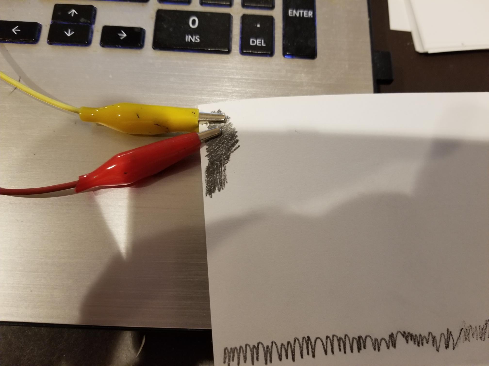
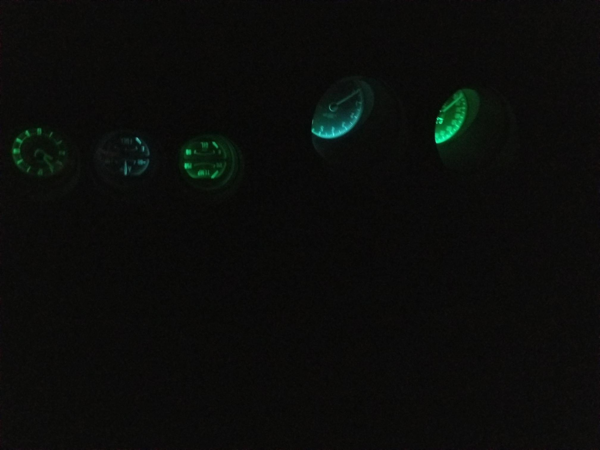
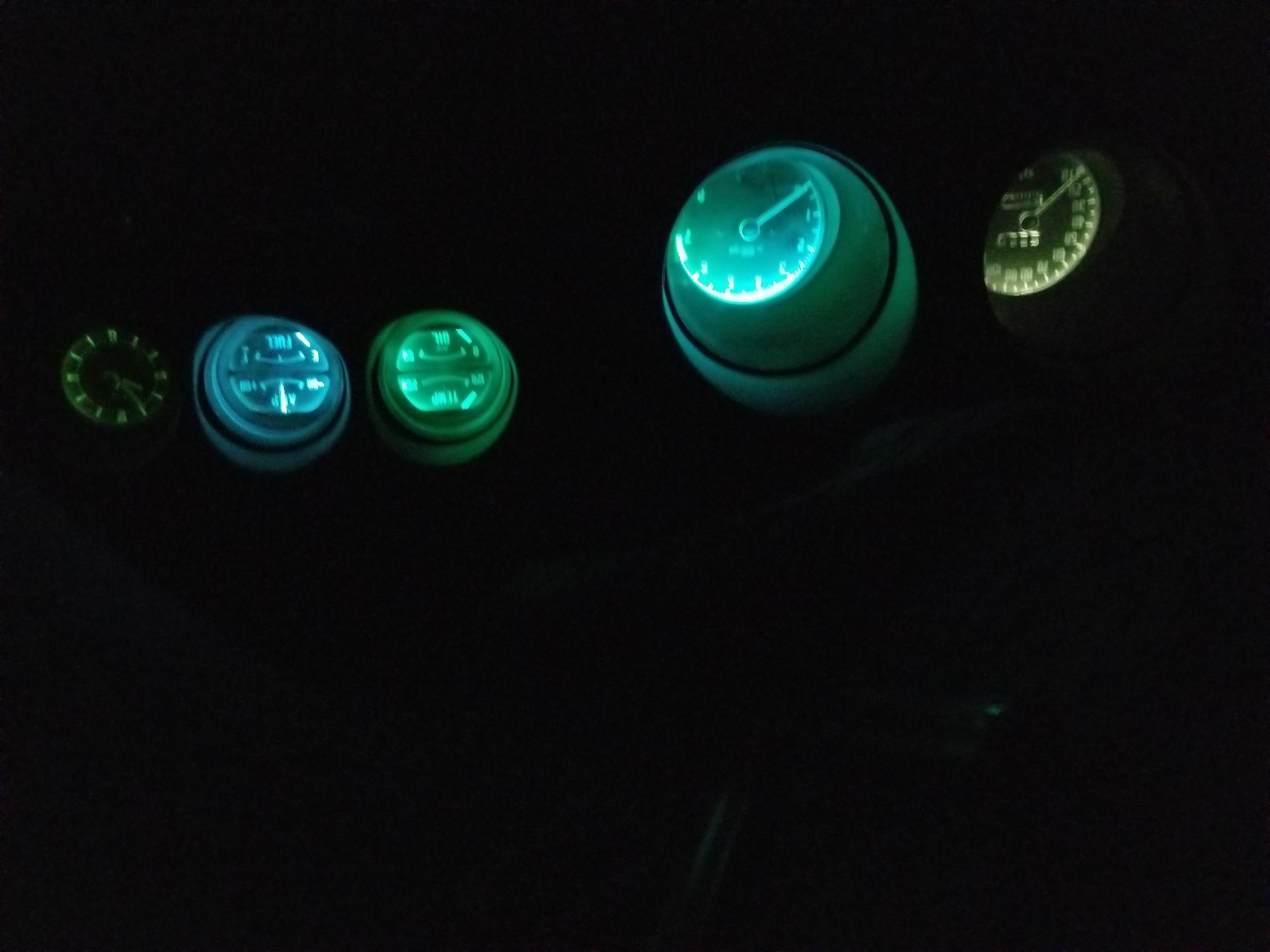
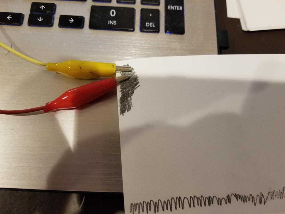
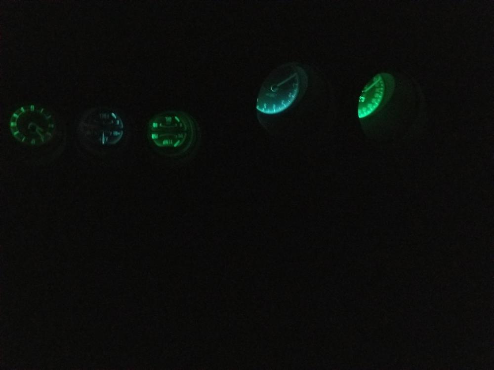
The website for the LEDs that I bought says that they are dimmable. I connected my dimmer and there was no discernible change. So I measured the dimmer. Mine measures out to be from 2 -11 ohms. It occurred to me that this might be too little resistance for the LEDs. I looked around but I did not have a spare dimmer of any sort. I could not find any of the resistors that I have foolishly saved over the years on the off chance that I would have them when I needed them. Its Sunday, I am trying to be a good citizen and not go out unless it is an absolute necessity. When I was a kid I had some hobby kits where you build things and do experiments. Anyway, here is the cool part (at least in my opinion), if you draw a box, on an ordinary piece of paper, and fill it in with an ordinary pencil you will have created a resistor. If you put an alligator clip with a wire attached to it on each side of the block you can measure the resistance that you just created. If you want less resistance put the clips closer together, more resistance – space the clips further apart. Homemade resistor So W3wilkes – the answer to your question is that the recommended LEDs are dimmable. I suspect that the dimmer in your Z (mine is a 1973 240z) may not work because the resistance in it is too low. But if you get a dimmer in the 0 – 1k ohm range you will be able to dim these LEDs. Here is a comparison: LEDs with no dimmer (speedometer, oil/temp and clock) - Green LED Tach and amp/fuel) White LED LEDs with 458 ohms of dimmer resistance The next image has no dimming, Incandescent lamps in the speedometer, and clock, Green LED in Volt/Temp gauge, and white LEDs in the tach and amp/fuel gauge You must take care in picking the resistance value if you mix incandescent lamps and LEDs. You might be able to get away with using the original dimmer if you have a few incandcent bulbs and some LEDs. I think I will try to go with one or the other. My conclusion is that I prefer either the white LED with a dimmer or the incandescent lamps and a dimmer, I might consider white LEDs in the speedometer and the Tach and incandescents in the 3 gauge set. If you have a question dont hesitate.


-
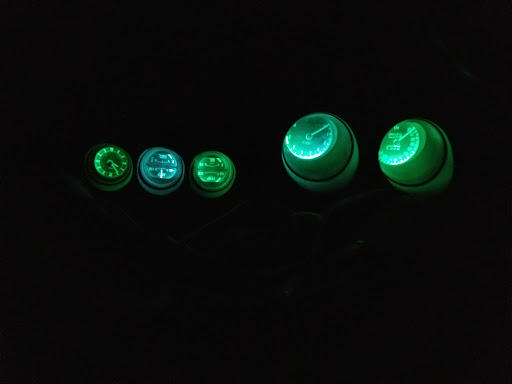
So, the white LEDs were to be delivered on 4/21, but they arrived yesterday 4/3. For comparison (image 1) I installed 2 white LEDs in the Tach and I installed 1 white LED in the center gauge (AMP/Fuel). The remainder of the gauges and the speedometer has Green LEDs. Green LEDs populate all gauges in image 2. image: 1 image: 2
-
Steve, That is a great point. I built a new harness and upgraded all of the wiring, thats what I am testing now. But lowering the fuse values is something that i missed. I installed relays and so I can do that in a couple of spots. I also removed the heater/defroster and AC and replaced it with a vintage air unit, so there is some wiring that is no longer active, as well. My original wiring was kindling. I agree with your suggestion on the 3 gauge set. When the white LEDs arrive I will give them a try. Regards, ron
-
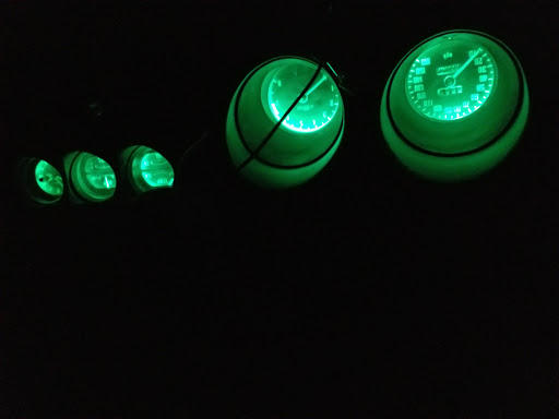
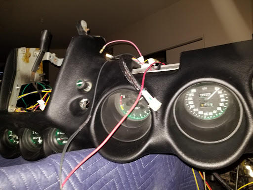
So some of the LEDs (SteveJs suggestion -thanks) that I ordered, came early, the clear version is (as luck would have it) still not scheduled to arrive until 4/21. I tried the red version (brake Light Failure) and the green version (turn signals) and you have to be patient - there is no abundance of clearance when installing the LED into the socket, but it fits. I then plugged the sockets into the respective holes. They install as they should and you will have no trouble with them bottoming out in the gauge causing the socket to become dislodged due to vibration ...etc. I was going to wait for the clear to finish this portion of the dash effort, but I am not the most patient person and I noticed all of the socket holes have green filters. I ordered 10 green and used two. I need 7 to light the tach, speedometer, and the 3 gauge set. I decided to populate the remaining 7 with the green LEDs. Could not stand not knowing what it would look like so I wired the lights to a battery. Yes the dash is upside down as I am testing the harness. And yes the gauge faces have a fair amount of dust on them but you get the idea. The wiring on this car separated the 3 gauge set lights from the speedometer and the tach with regard to the dimmer. When I was redoing the harness I tied all 7 bulbs to the same ear on the dimmer - so they all dim at the same rate. So these LEDs are a lot brighter than the incandescents. If they are too bright I can dim them down. I don't recall anyone ever claiming that the z gauge incandescent lights were overly bright. Once again, thanks SteveJ - I appreciate the help. regards, ron

-
Gundee, Thanks for responding. I am sorry to be the bearer of mixed news. The URL that you sent has a 360 deg view button, one of images is a dimension view. This is the url for that dimension view. https://www.superbrightleds.com/moreinfo/ba9s-ba7s/ba9s-led-bulb-4-led-ba9s-retrofit-car-classic-car-bulbs/6/. I have some of these and I believe that they fit in the speedometer and tach (will check if you need me to), but they do not fit in the gauges - oil temp, amp fuel or clock. As you can see the length is 26 mm for this bulb. The length of the bulb listed by SteveJ is 18 mm and I believe it will fit everything. ps 1 (3/23/20) I just checked and the 26 mm does fit in the speedometer and the tach. ps 2 (3/24/20) sorry to do this but I did not want to mislead anyone. I was working on the harness in my dash, and inadvertently put just the slightest amount of tension on one of the bulbs for the speedometer. It came out of its socket. So it turns out that the 26 mm LEDs do in fact hit the green lens inside the speedometer and the tach. I was fooled because one of the bulbs seemed tight enough, but it would be a mistake, in my opinion, to use the 26 mm bulbs anywhere on the dash. So to tie a bow around this the original incandescent length is approximately 20 mm. The alternative that SteveJ has suggested (thanks again) is 18 mm. There is one more critical dimension. There are 2 posts that extend out of the barrel of the bulb. they provide a key/locking scheme to keep the bulb in the socket. I apologize if I am confusing anyone. Anyway, on the suggested alternative there is a collar. That collar is no doubt larger than the socket, so the distance from the post on the barrel to the collar could be, likely is, critical if it is too short then you will not be able to get the bulb in the socket. This dimension is not available, so I cant be certain that the alternative will work. I will update this when I get the bulbs that I ordered. Sorry for the confusion. regards, ron
-
Thanks Steve and Chuck. I will give them a try and confirm. Unfortunately it will take a while since they will not deliver to me until 4/21. regards, ron
-
So, I am replacing the dash on a 1973 240z. In the process of putting everything back together I tested the bulbs for the gauges. I believe they are mini bayonet BA9s 1445. This is a 3.4 W incandescent bulb. I think that is a lot of power (watts = volts X current) for so little light. Anyway, I was curious if anyone has a direct LED replacement for the mini 1445. The version that I have fits some of the enclosures eg. the speedometer and tach, but are too tall for the gauges and the clock. Thanks in advance for your assistance.
-
Thanks for getting back. Makes perfect sense. Appreciate the insight as I have not previously installed a windshield. regards, ron
-
Grannyknot, I am also restoring a '73 240z and I too have begun to re-install my interior. You have been a big help to me in the past. Having said that I was curious why you recommend installing the windshield before installing the dash. Thanks.
-
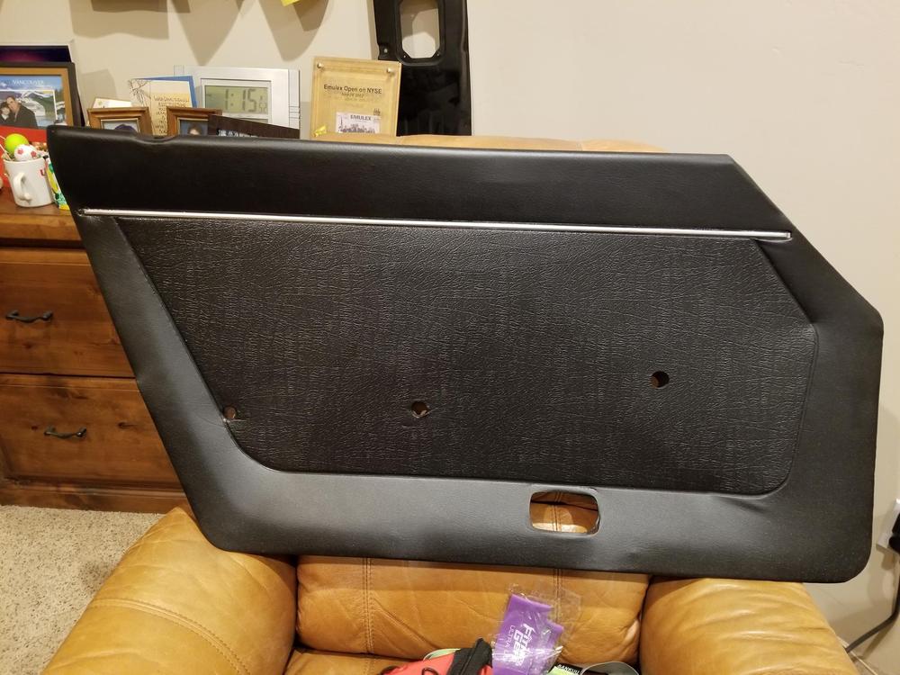
okay, so you asked if anyone tried to remove the strip from the card. I tried heat, but chickened out quickly because I was concerned about melting the 45+ year old vinyl. My door cards and vinyl were in very good shape, with the exception of the strip. I really did not want to take a chance on ruining the vinyl. I was going to change the color of my vinyl and decided to go with the SEM spray for the vinyl and the Spaz Stix for the strip. The picture below shows what I was able to achieve. If you are retaining the current color of your vinyl then the problem is a bit easier as you only have to tape the vinyl tight to the strip. One word of advice the chrome spray is pretty good but not great. Your results are improved if the surface is really smooth, so dont sand, there is no paper that is really fine enough, but you do need to remove anything that is loose on the surface of the strip. I am not trying to discourage you from trying to remove the strip. I am concerned about getting the area hot enough to separate the strip from the vinyl without melting the vinyl. Best of luck.
-
Hardway, I just wanted to thank you for addressing the issue regarding the images. It's a big help. regards, ron
-
Hardway, Thanks for the effort. Its Christmas, there is no rush. When their site comes up we will have the images. Thanks again and Happy Holidays
-
I am starting to rebuild my 240z seats and I remember seeing an article by hardway - which is in the knowledge base. There are a number of pictures which prove to be helpful. Unfortunately I did not print out a copy when I looked at it the last time. When I bring the article up where thepictures are supposed to be is a message saying that they are "not available". double click the picture below to go to the article and see the missing images. Can someone explain if there is a temporary problem with the website or is it an issue with my laptop settings...etc. Thanks in advance for your assistance. regards, qz16
-
I agree removal of the strip is a very bad idea. I am going to prep the card, use the SEM spray system and then finally mask the card and spray the strip with spaz stix spray on chrome. I believe the SEM finish will handle the tape for masking better than the spray chrome. I will insure that everything is fully cured before using any masking tape. I dont think that a tape line will be apparent when the job is complete. Thanks again for the help regards, q
-
First of all thanks for the responses. Secondly I have some experience with the SEM product line and everything (plastic and vinyl) has been completed ( repairs to plastic and vinyl as well as the color change. The SEM product line is amazing and everything turned out beautiful. The only alternative, albeit destructive, that I can come up with is hope that the vinyl under the strip has not adhered to the card, cut through the vinyl around the plastic strip and gently scrape out the strip still attached to the underlying vinyl. Then you would have to find a chrome strip that is a bit wider than the original to cover up the damage. I believe they sell replacements for this strip but do not know if they are wider than the original. Another alternative is to mask it, but the chrome strip is no longer really chrome looking, it looks almost midnight blue, so rather than mask the strip, mask the card around the strip and use SEM plastic prep on the strip, and then remove the mask and paint the entire card with black SEM color coat. When i decide which route to take I will update this post. Once again thanks for the help.