qz16
Free Member
-
Joined
-
Last visited
Everything posted by qz16
-
Does anyone have a solid understanding of whether or not vintage dashes is a real business? I have been trying to get a 240z dash since 9/13/18. My understanding is that these are stand-up guys that can be trusted. They supposedly produce a good quality product, but they do not make it easy to understand when they might be able to provide it. If anyone has any information I would certainly appreciate it. If it is not available then I need to go in a different direction with my project. I understand that they are now making progress on supplying a 280z version, have they given up on the 240z? Thanks for your assistance
-
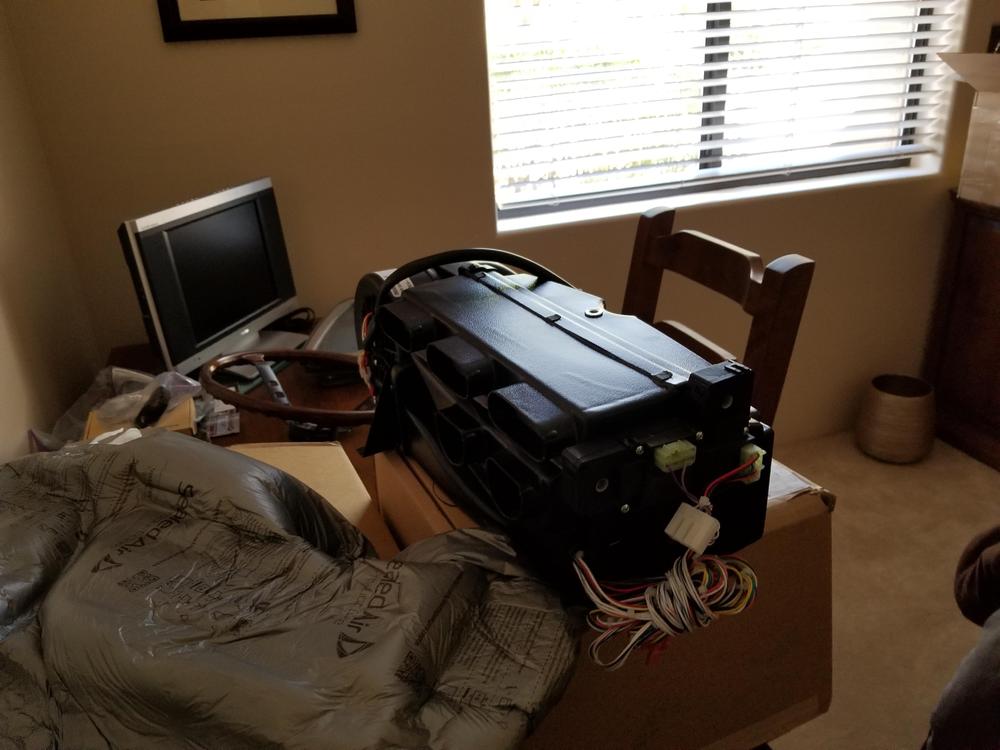
I was asked to regenerate the parts list order/s required for the install of the vintage air mini gen II. Below is the information for the mock-up box that vintage air loans out to help customers understand the size of the package that has to be installed inside the car. It helps you understand where to put the evaporator and hose connections. I cotacted vintage air and this was the info that they gave me. I decided that in my case it would not be necessary to actually mock-up the install. I was confident that I could get everything to fit based on other installs that I had read about. I would add that vintage air was responsive and helpful. “The shipping box measures 26 x 20 x 20. The evaporator assembly measures 11" high by 11.5" wide x 8.5" deep and will sit up against the firewall and a small portion of the bottom of the unit will sit down below the bottom of the dash. You would see about 2" to 3" of the bottom of the case. The switch kit we have for this system is separate from the original and can be placed under the steering wheel or in the console out of site. You can go to our web site at autoacsolutions.com and to to instructions for more on installation of the system. Click onto our indash a/c instructions. If we can be of more assistance let me know. I will be working messages off and on through the weekend and will try to answer as soon as possible.” The only disappointment that I had with Vintage air was that they could make it a great deal easier to order a complete system. I would suggest that they spend some time reading some of the different popular forums searching for reasonably good installs and create a parts list for some of the popular classic installs. Obviously, it would be nice to place a single perfect order that contains everything you would need. I have been able to do this a couple of times. Sadly, this was not one of those times. Below is the first order that I placed. The error of my ways is immediately apparent: I did not use the Horizontal slide panel. I did use the York to sanden conversion bracket – but I have heard that there are better solutions out there. I used vintage air’s ez-clip kit. I also purchased their plier which I think is well worth the expense. It was easy to use. It allowed me to create the customized hose routing that I wanted. I am still in the throws of restoring my car so I do not have any experience with the quality of this connection system, but I have high hopes that it will not leak. I liked the idea of using the bulkhead connectors and so I bought two. One for the AC hoses and one for the heater hoses. If I had to do it again, I might separate the hoses a bit more; just to make it easier to connect the hoses. The bottom line is don’t get ahead of yourself. Order what you need. As best I could tell there is no discount for larger orders with the exception of shipping cost. 66005-VUZ-A MINI GEN II W/DEF EA 1.00 0.00 470.00 470.00 main unit (heater/def/AC) inside car 49110-SHQ HORIZ SLIDE PANEL (MACHINED) EA 1.00 0.00 75.00 75.00 slide controls 63375-VUE DEFROSTER DUCTS (SET) EA 1.00 0.00 19.95 19.95 04808-VUQ SD-508 POL COMP O-RING 134a EA 1.00 0.00 249.00 249.00 compressor 15815-VUB YORK TO SANDEN CONVERSION KIT EA 1.00 0.00 60.00 60.00 conversion bracket to mount compressor 547002 HOSE KIT,E-Z CLIP UNIVERSAL EA 1.00 0.00 360.00 360.00 clip kit (hoses+connectors) 420000-VUR EZ CLIP PLIERS EA 1.00 0.00 78.00 78.00 tool to install ez-clips 07323-VUC DRIER W/TRINARY SWITCH EA 1.00 0.00 59.00 59.00 drier 389602 STRM 2 WAY INLINE BKHD #6-#10 BLK EA 1.00 0.00 44.00 44.00 bulkhead connector /bracket (AC) 389803 STRM 2 WAY INLINE BKHD #10-#10 BLK EA 1.00 0.00 44.00 44.00 bulkhead connector / bracket (water inlet/egress for heater) 03263-VUC PARALLEL FLOW COND 14 X 24 W/BRKTS EA 1.00 0.00 149.00 149.00 condenser (to cool air before drier and return to evap) My second order was just foolish. Do not order hose connectors until you really understand your hose routing. In my opinion this is not possible until everything else is installed. With regards to the connections inside the car. My install works but, it would have been a lot easier for me if I had realized how little room there is in the cockpit. If you understand how difficult it is to make bends with these hoses and how much room you need to actually tighten the connectors then placement of the bulkhead connectors can be improved. This influences the selection of connector style (90 deg., 45 deg. straight, etc) I ordered a number of incorrect connectors. 347160-VUR EZ CLIP #6 STRAIGHT EA 4.00 0.00 17.00 68.00 AC and water connectors 347100-VUR EZ CLIP #10 STRAIGHT EA 1.00 0.00 19.10 19.10 347200-VUR EZ CLIP #10 45 DEGREE EA 1.00 0.00 24.50 24.50 347180-VUR EZ CLIP #8 STRAIGHT EA 4.00 0.00 16.00 64.00 347380-VUR EZ CLIP #8 90 DEGREE EA 2.00 0.00 18.25 36.50 318000-VUR EZ CLIP AC HOSE #10 PER FOOT FT 8.00 0.00 5.75 46.00 347962-VUR EZ CLIP #6 CLIP EA 8.00 0.00 0.60 4.80 347960-VUR CLIP #6 CAGE EA 4.00 0.00 1.05 4.20 347902-VUR EZ CLIP #10 CLIP EA 4.00 0.00 0.65 2.60 347900-VUR CLIP #10 CAGE EA 2.00 0.00 1.40 2.80 347982-VUR EZ CLIP #8 CLIP EA 12.00 0.00 0.60 7.20 347980-VUR CLIP #8 CAGE EA 6.00 0.00 1.15 6.90 Third order: 347260-VUR EZ CLIP #6 45 DEGREE EA 1.00 0.00 20.00 20.00 more AC /water connectors and clips 347300-VUR EZ CLIP #10 90 DEGREE EA 2.00 0.00 19.75 39.50 347900-VUR CLIP #10 CAGE EA 2.00 0.00 1.40 2.80 347902-VUR EZ CLIP #10 CLIP EA 8.00 0.00 0.65 5.20 347960-VUR CLIP #6 CAGE EA 1.00 0.00 1.05 1.05 347962-VUR EZ CLIP #6 CLIP EA 2.00 0.00 0.60 1.20 121018 HARDLINE 90 HEATER FITTING EA 2.00 0.00 7.00 14.00 121004 HARDLINE STR HEATER FITTING EA 2.00 0.00 7.00 14.00 The final order that I placed was for controls so that I could use the original 240z climate control panel. 11458-VUS SWITCH 3 SPEED BLOWER ROTARY EA 1.00 0.00 11.25 11.25 knobs I needed to use orig. 240z control panel 49457-VUI KNOB CONTROL (ROTARY) EA 1.00 0.00 1.50 1.50 20558-VUP LABEL BLOWER SWITCH EA 1.00 0.00 3.00 3.00 I know some of you will be interested in the total cost of the install. I made a few mistakes that were somewhat costly. And the total cost of these orders also includes the EZ-clip system and plier and extra parts. So, if you add all of the figures the total is approximately $2154. I would estimate that there is approximately $300 worth of material that I did not need or use (panel, bracket, hose connectors ..etc) There is a $75 plier. I did not calculate the additional charge for the ez-clip system. The reason I bring this up is to be fair to vintage air regarding cost. If you compare the price of their system to another vendor make sure that you are comparing equivalent systems. Given the additional information/experience that I have at this point I would make the same choice and go with Vintage Air. I hope this helps and if you have a question, I will try to answer it.
-
Patcon, thanks for the comment - I am not trying to be coy its just that sometimes on forums the topic at hand morphs into commentary on who likes what manufacturer. Anyway, I did not know what to buy and decided to go with a brand that I have used before. My base and clear coat are PPG deltron, very pricey stuff - not sure if it is worth it or not. For the epoxy primer I went with PPG OMNI MP 17x series. I have read and seen a number of complaints and stories about difficult to spray, gummy, etc. I have nothing but good things to say about the product but that is not based on a ton of experience. It sprayed great, It looks fabulous - but it is primer. No orange peel, no problems with gassing off too slow or too fast. It appears to be somewhat self leveling. I put two coats on. My primer gun is an air gunsa AZ3 with 1.8 HTE tip. Sometimes people blame the product when it is a skill issue, or equipment issue, or setup issue. I'm at the point that its just easier to blame me. I have heard good things about Nason products. Based on your comment that you sand everything I assume you are using an etching product or a water based product like rust dissolver. I think you are correct as long as you wash down the panel and dry them thoroughly the chemicals work great. I have come to the conclusion that the only time to use rust converter type products is for place you just cant get to very easily, like the bowel of a rocker panel, or into the fold of a fender. And in these types of situations it is more of a wing and a prayer for areas that you cant see the rust. This morning I tore into a fender that I had used rust converter on a year ago. I did this because I saw a pinhole in what was good metal a year ago. I kept hacking away trying to get to clean metal and what I found was that the converter had worked on one piece but a second piece that was sandwiched to it showed no sign of reform. The rust was fresh and active. So today I am less of a fan of rust reformer/converter than I was 48 hours ago. I am just a DIY guy and so it is a bit of a production to switch from mechanical work to bodywork to paint, so like you I am not able to put paint on the same day that something gets stripped, unless I was going to rattle can it. I am not sure what is best - to use the etch and let it dry to protect the piece until you can get to it or to deal with the rust if you are unlucky and it does form. I have very little control over the climate in my garage, so I will not spray below about 55 deg. and never even tried above 40% humidity. I am lucky though I live in phoenix so temperature and humidity favor me most of the year. Biggest problem I have is very quick drying when the temps are high. Turns out that most of the time when I do something foolish I just need to lick my wounds, the right answer to my mistakes rarely turns out to be an easy or quick solution. But I will not make this one again. Once again, thanks for the response. regards, ron
-
granyknot - thanks for the quick response. I am using Rustoleum Rust reformer. I am also using eastwood rust dissolver which is water based. it is especially useful on pitted areas. I scrub it in with a scotchbrite, wire wheel it, apply pre prep, and dry it. I have used eastwood fast etch, but try to stay away from it as much as possible. As I understand it etching chemicals are stronger, but can only be applied on bare metal. This limits their use in my garage. Even when I have the right situations I always attempt to use the rust dissolver first. I also use eastwood pre prep for wash down and dry with compressed air before I prime a panel. I really like the eastwood products that I have tried. Sometimes their stuff seems a bit pricey, but I have found it to be high quality. The only thing that bugs me with Eastwood is that it takes forever for them to process, ship and deliver. All of the coatings (paints/primers) that I am using are 2k. I have used gel type strippers, but have not used any gel type rust removers or gel type etching products. I know about the chalk like powder. Have not seen it happen all that much. Good advice - thank you.
-
I did a foolish thing! Background: Most of the car has been taken to bare metal. The rear clip is painted. So, I am in the process of doing the final prep work to paint the remainder – fenders, doors, hatch, hood, etc. I was trying to finish some of the remaining pieces, but you know how it goes. Every time I passed a door I saw something else, a tinge of rust color I thought, a place that would benefit from a little bit of filler. I just would not let it go. One of my favorite saying is that the enemy of good is better. Unfortunately, I can remember it but I am still unable to practice the sentiment. My total experience spraying is limited to 1.5 cars, an MGB which came out fairly nice and the z which is turning out even better. I have no experience with Epoxy primers, or Etching primers. Fast forward based on what I have read I decided that I did not see the benefit of applying an etching primer. On the other hand, the corrosion resistance and the concrete separation between anything below it and what would be laid on top of it was attractive to me. So, my plan for the remainder of the car was to continue doing most of my body filler work on bare metal, and to apply an epoxy primer. This would be followed by a Urethane (high build) primer, base coat and clear. Of course, there would be the appropriate amount of block sanding between spray layers. Now I promise to TRY not to be sensitive. I really do want to learn, so don’t hold back if I say something less than brilliant please do not hesitate to point it out. My understanding is that Rust is bad. It should be completely eliminated before any primer/paint goes on the car. That’s why we took most of the bucket to bare metal. Having said that there are places that you just can’t get to, or just don’t want to because the risk vs. reward is just not balanced in your favor. So, there are places where I have (dare, I say it) sprayed rust reformer or converter. I’ll give you an example – the front of the door was taken completely down to bare metal. The back of the door - not so much. It was sanded, and when I got to the edge of the door skin that wraps around to the back I wire wheeled them. This revealed some pitting and some superficial rust. On the door skin I removed the rust with Eastwood rust dissolver, a very good product in my opinion. But on the rust on the frame of the door I used rust converter. Now I know you are thinking that this was a rookie error. However, if I were going to do the perfect job then I would need to remove the skin from the door to make sure that there was no rust behind the skin, but I know that this task is beyond my skill level, sure I could get the skin off but could I get it back on the door in as good a shape as it is now? So, using rust converter was small potatoes given that I was not going to remove the skin. Also, to be honest, the car is 45 years old it was obviously mistreated at one point in its life and the rust that I am seeing is fairly superficial so I think it is a reasonable bet that these doors will last a long time given the level of care that I am applying to the car. I apologize if this is boring you, but here comes the punchline – I believe in the notion that if I can see rust then there is always some that I can’t see, and I can’t deal with anything that I can’t see. So, I foolishly spray converter into the door frame, it will not do much good but it makes me feel better, it wont in my opinion do much harm either. But now I have the darn can in my hand and I go one step farther. I spray it on the entire back of the door, and since that was such a good idea, I spray it on the back of my fenders, and the back of the headlight coves (I think they are called that). By the way before I sprayed the rust converter I roughed all of the surfaces with 80 grit. Everything looks good. It looks uniform. If there’s any rust I converted it – hell if the rust were English Pounds I would have converted those pounds into a million U.S. Dollars. Now everything is drying and I start thinking. Then I start reading. And now I start worrying. I am totally confused by what I have read. I know that I should not cover rust with epoxy primer, and to my knowledge when I spray the epoxy I will not be covering any rust. The question is can I spray epoxy primer over rust converter? So, I decide that the damage has already been done and I need to do some experimenting. I don’t have to spray the epoxy on the back of the fender so this will test whether I can properly spray epoxy primer on bare metal, and body filler. My inspection doors have body filler on the top side, but nothing on the back side. So, this will show if I can properly spray epoxy on just bare metal (the backside). The headlight coves – I decide to spray epoxy on the top and backside. This will give me some insight into what happens when you cover rust converter with epoxy. In this particular case below the rust converter on the back of the cove there is rust free bare metal ( they were sand blasted), which I then sprayed rust converter on. Now as I have come to understand it epoxy primer sprayed over rust converter will cause the primer to lift. So, my foolish mistake is that I thought the rust converter would not hurt anything and it might help prevent future rust from forming. This in my opinion (now) really was stupid. Conclusion: All of the pieces that I sprayed turned out great. The epoxy has been on for approximately 4 days at this point, I think that is somewhat important because most epoxy primers have an open window of 72 hours.. The fender with the mix of filler and bare metal – sure you can see where the filler is but the epoxy went on fine as it should and the filler will certainly be covered by the high build urethane that follows. – so, no harm no foul. The inspection doors same thing no issue on either side. The headlight coves came out perfect. The epoxy covered the rust converter – you would never know that there was any converter applied. So, I called the Rustoleum company and spoke with one of their specialists. They in no uncertain terms told me that you definitely should not cover any rust with epoxy primers. Furthermore, you should not cover their rust converter with an epoxy primer. I asked if that meant that I needed to sand off all the converter. I was informed that would not be necessary. Rustoleum makes a product (a shock) called clean metal primer. It could be applied over the converter and either urethane primer or base color could be sprayed on top of the clean metal primer. So, I know that you will be glad to hear that this tale is almost ended. My question to anyone with direct experience: a. If you rough the surface (covered with rust converter) with 80 grit can you spray Epoxy primer over it or will it lift over time? b. Is there anything (other than rust) that you should not spray epoxy over? c. The epoxy primers that I have looked at all say that you can spray them on bare metal, properly prepared paint, body filler ...etc. If epoxy primers require a mechanical bond and you rough with 80 grit why can't you apply epoxy over just about anything. I purposely have not mentioned which epoxy primer I am using as I do not want to get into a discussion of which primer is better than another. If you do like one better than another please mention it. As always thanks for your patience and for sharing your knowledge.
-
grannyknot - this is great - thanks for the pictures. Good to see that you were able to use the same product on the vinyl and plastic as well as the steel upper dashboard finisher (not sure what its real name is) 2nd from last picture. thanks for the tip on the clear. BTW - looks like a great job.
-
David F - oiluj did a very nice job. I was not doubting you - it just sounded difficult to me. I actually thought about doing something similar, but was not able to get it to work reliably. Oiluj came at it differently and has my respect. regards, q
-
I like the interior. How old was the SEM interior at the time of this picture. Is that the original dash?
-
In addition to my post here I did send an email to SEM Products. Talk about responsive. One of their specialists got back to me almost immediately. While he was not able to answer which product would most closely resemble the original appearance he did clear up a couple of questions. Here is his response. Thanks for your interest in SEM Products. You choice for a black will be determined by gloss level. Landau Black is our most common interior black, it is a semi-gloss. Another choice is 15243 Satin Black, a little less gloss. None of our Color Coat aerosols, including Landau Black, require a clear coat unless it is necessary to adjust gloss.
-
My son and I are restoring a 1973 240z. We are converting the interior from “tan/brown” to black. We will be replacing the seat foam and vinyl, and the headliner with new material. I am planning to use the SEM Color Coat system for the remaining plastic and vinyl pieces including the door cards. There are a number of choices and I do not have the experience to know how subtle or substantial the differences are within the color coat system. SEM offers: landau black #15013, gloss black #15233, satin black #15243, high gloss clear #13003, satin gloss clear #13013, and low luster clear #13023. Does anyone have experience with these variants? Which in your opinion most closely resembles the original Datsun appearance? Does landau black require a clear to protect it? Thanks in advance for your assistance. Ron Q.
-
David F- your plan to "retain the original levers and simply mount the new control mechanism on brackets that are operated by short connecting rods from the original levers" will be quite challenging. I am sure that you will figure out a way to use the original fan control switch which will allow you to retain the look of the original knob. That will be a nice touch - I'm jealous. To all that have responded - I appreciate the kind words, "thanks", and "likes" - Thank you.
-
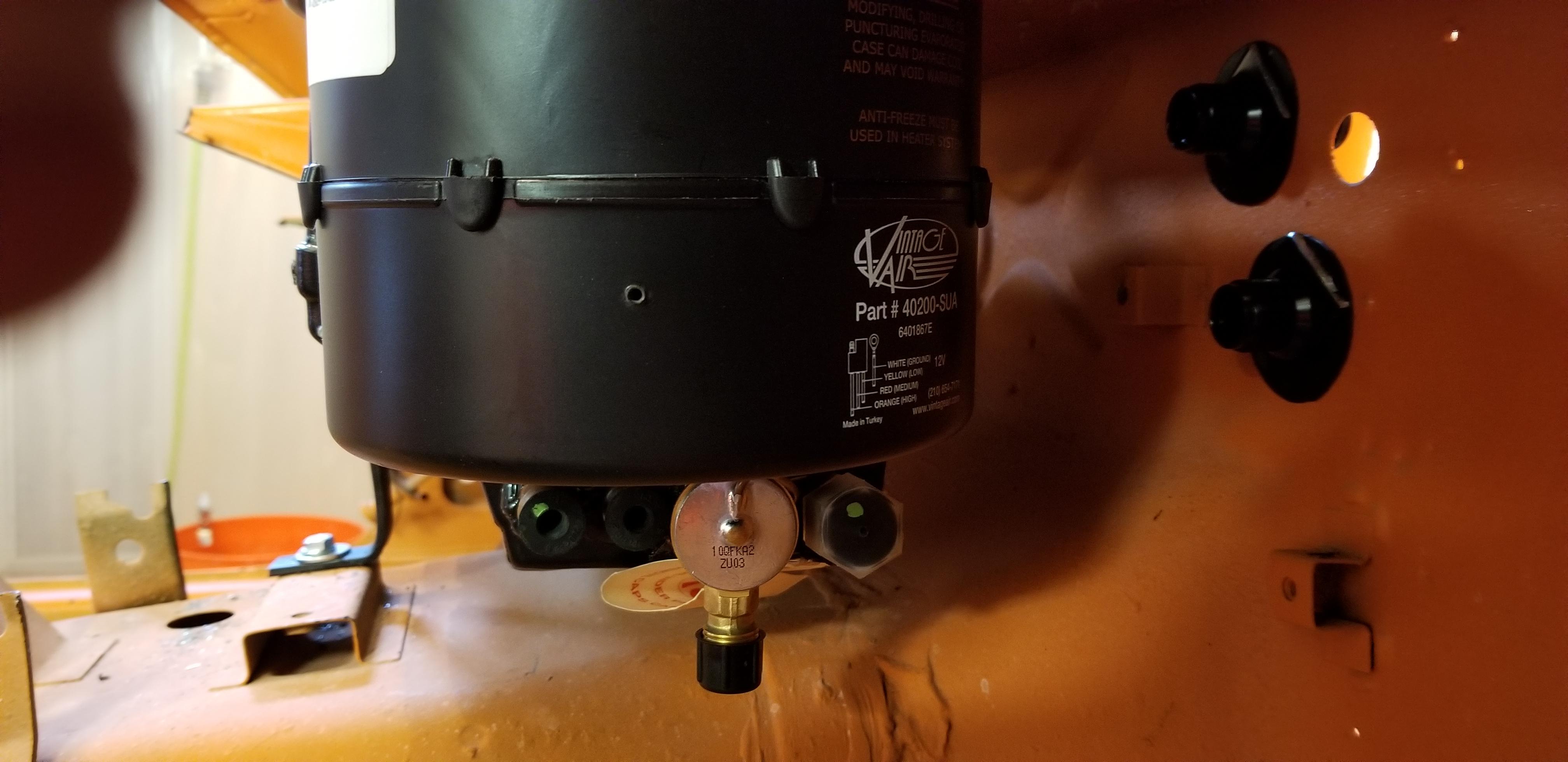
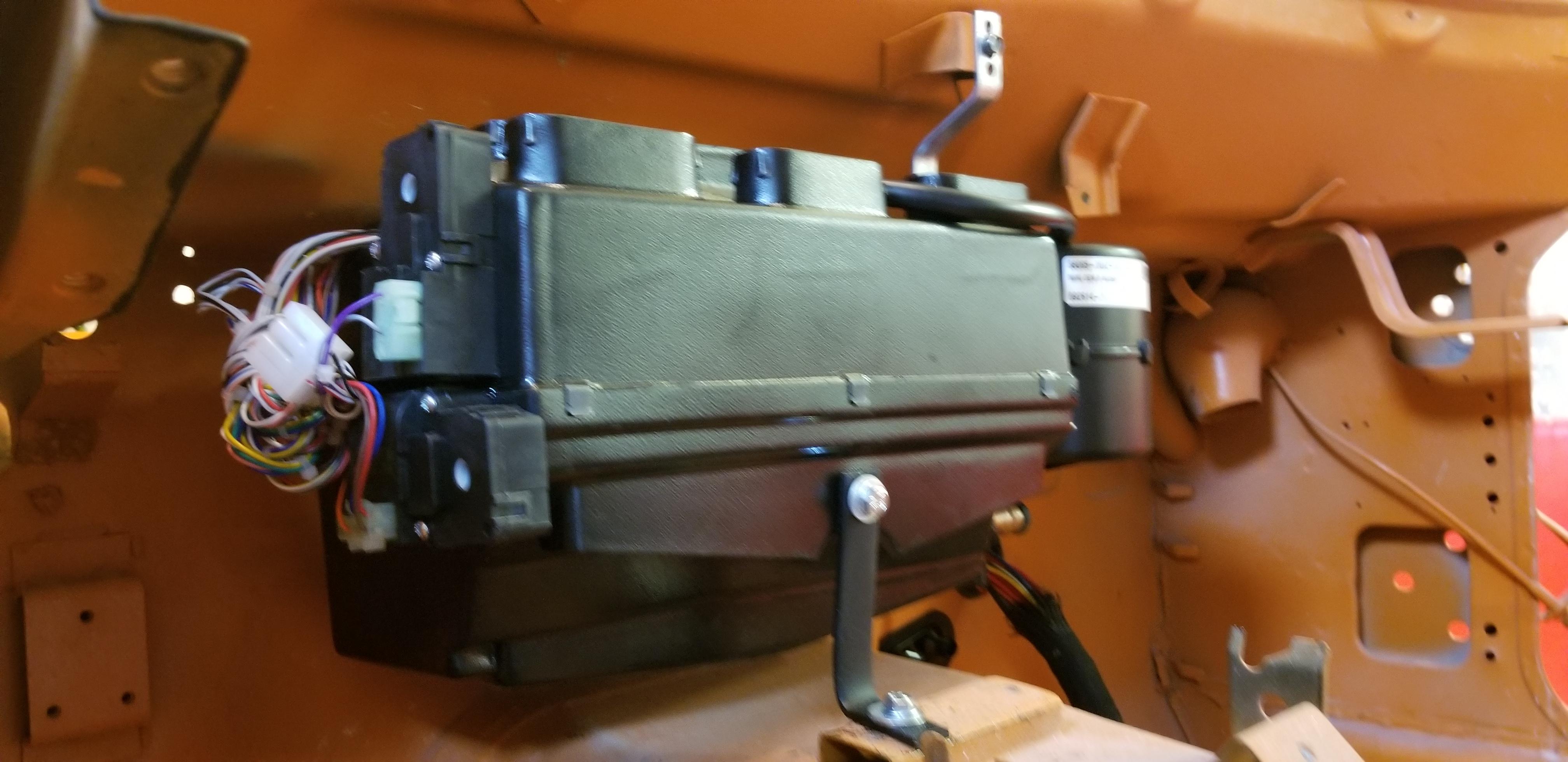
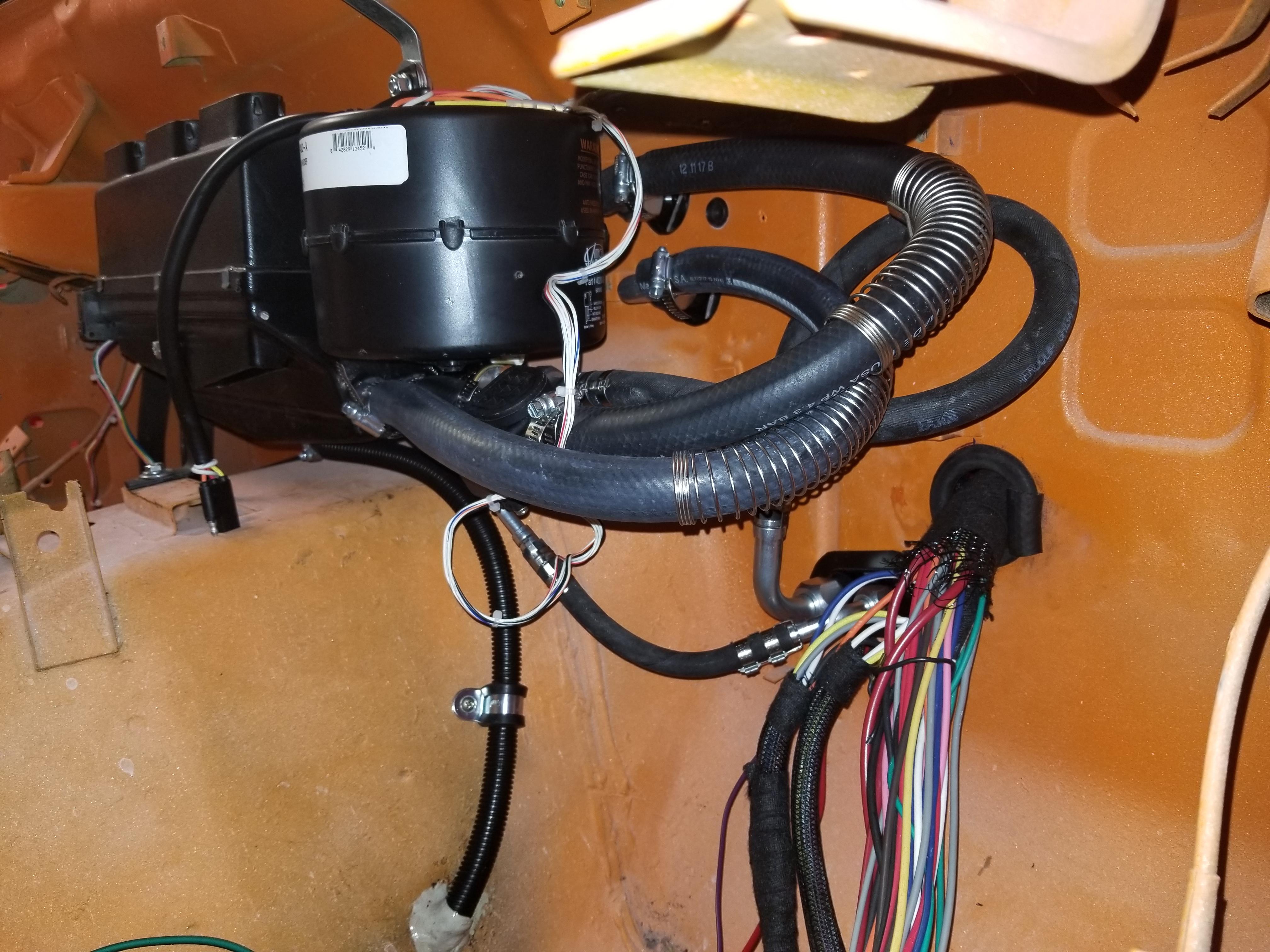
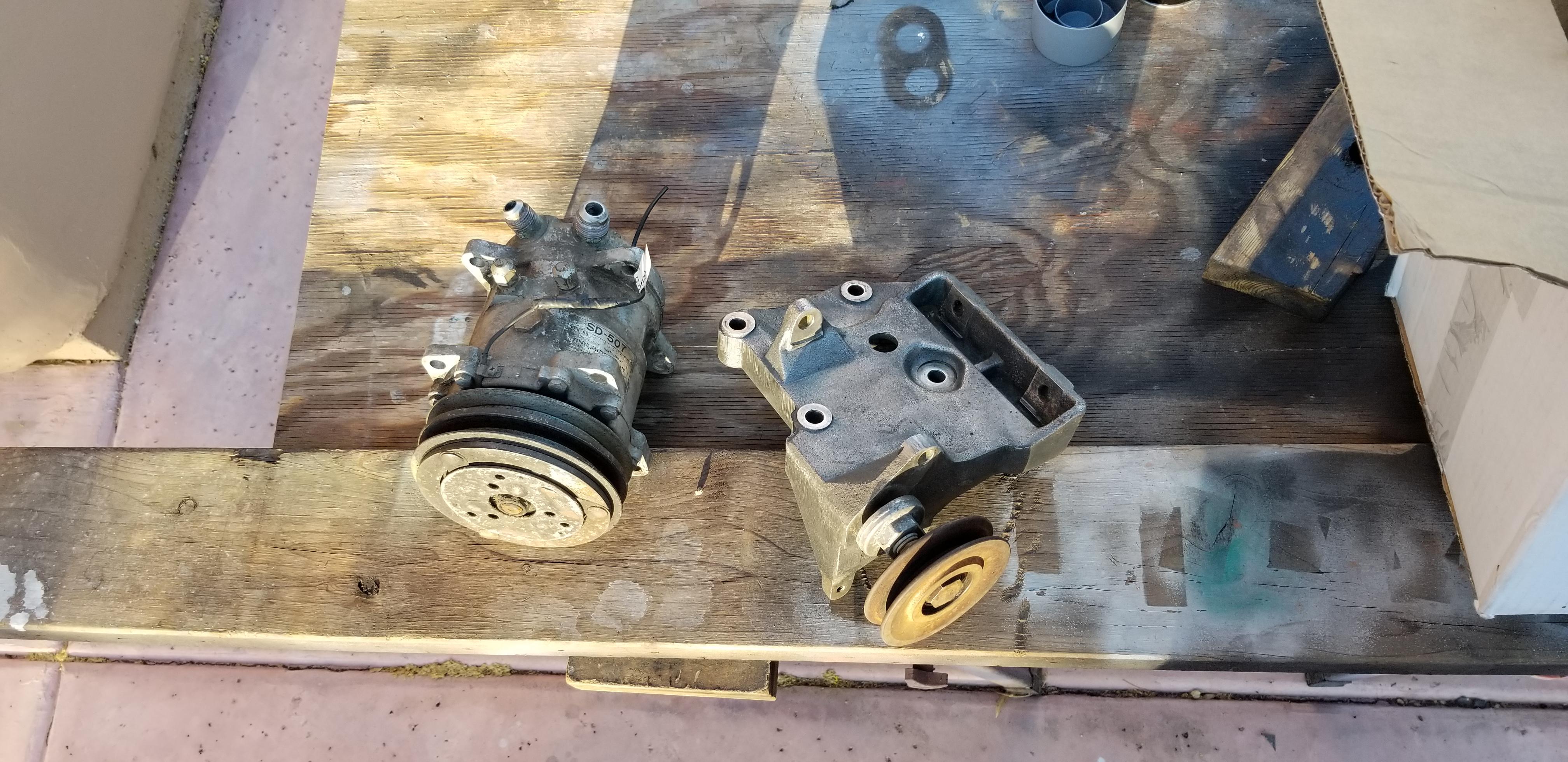
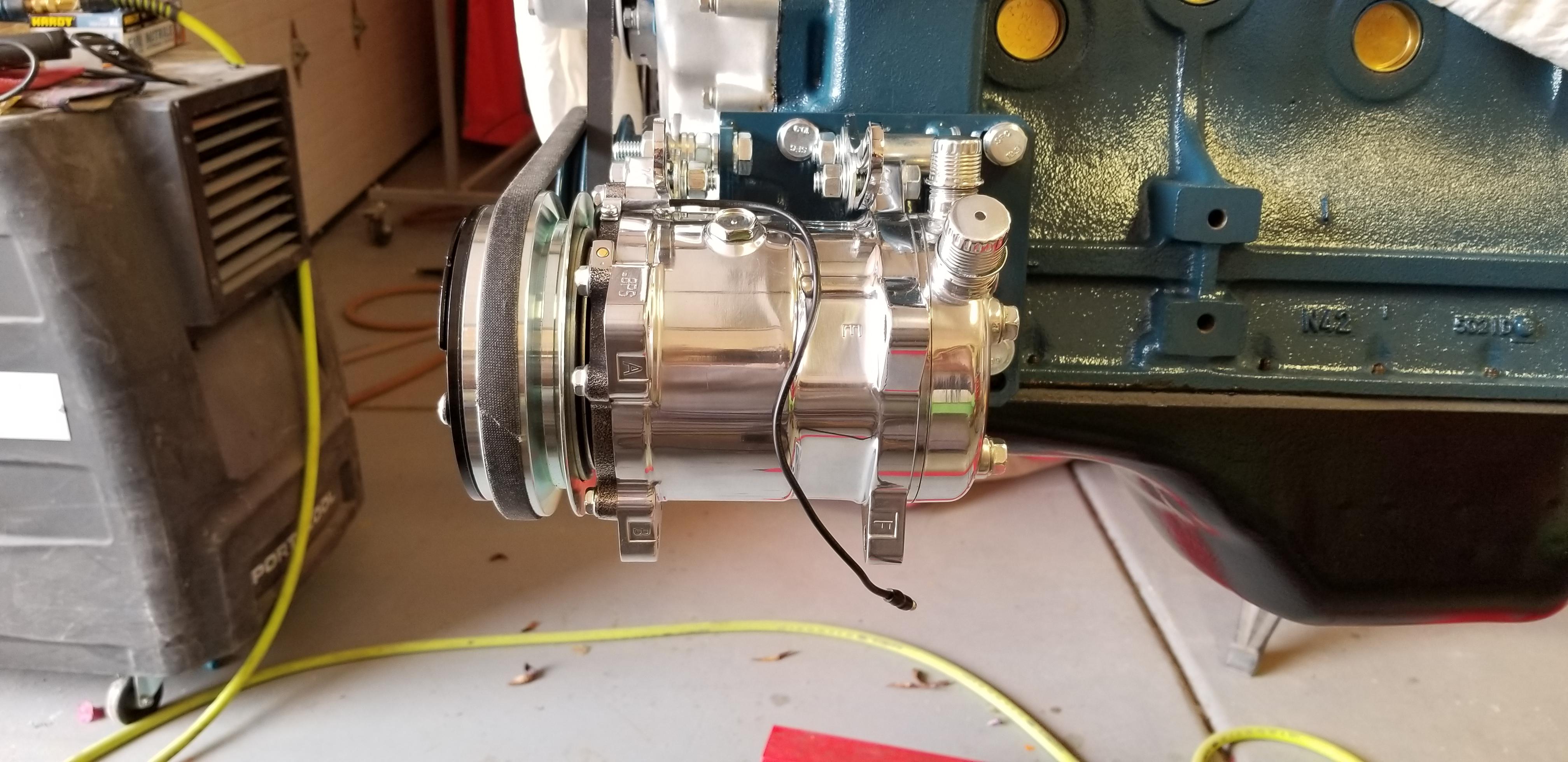
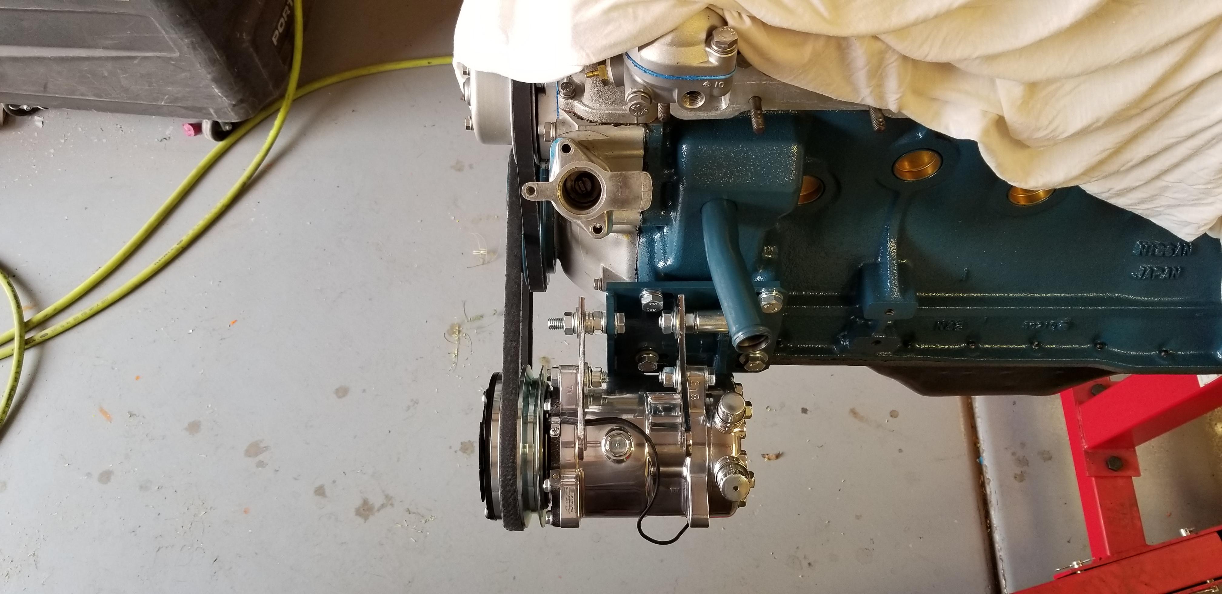
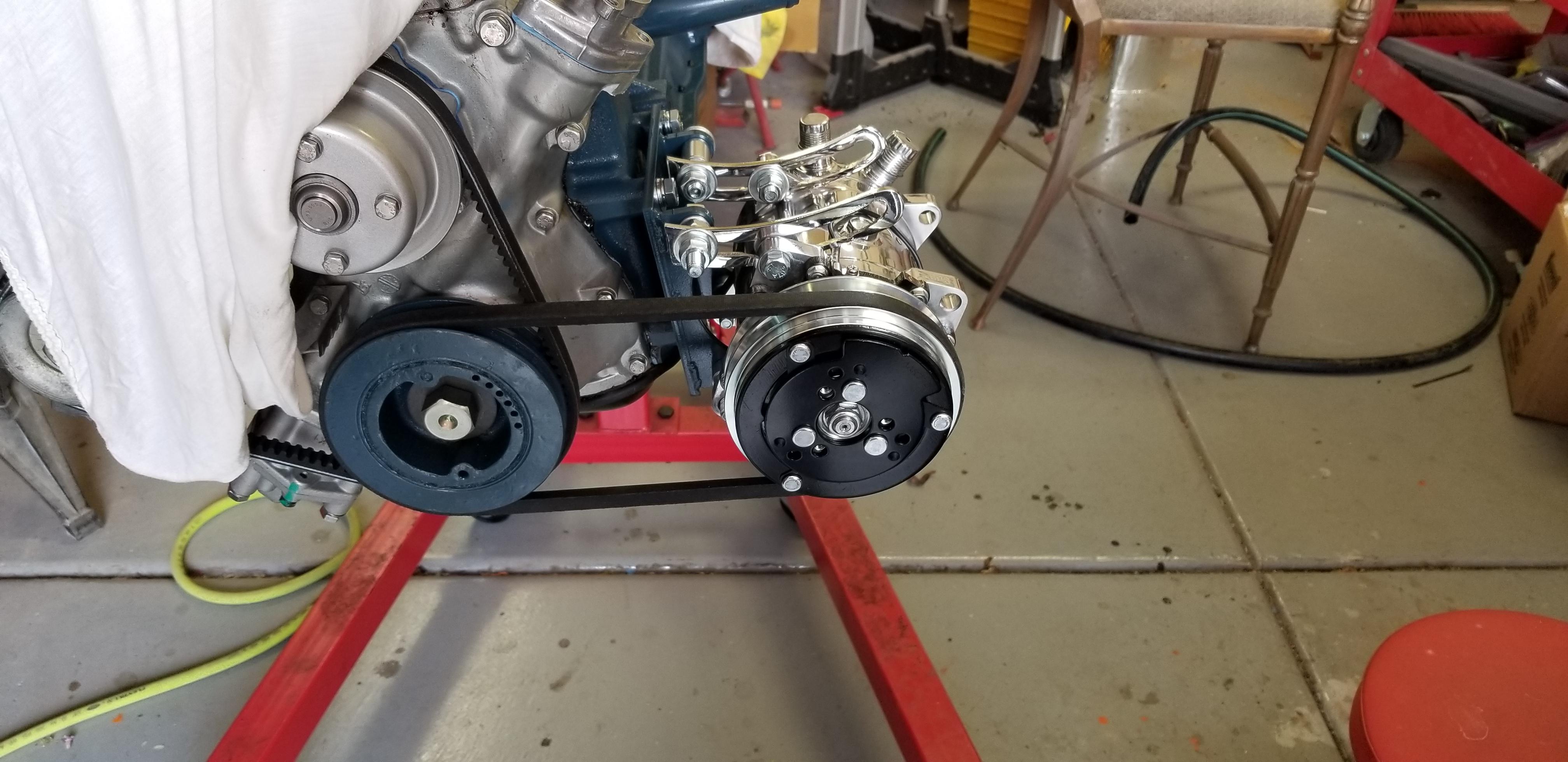
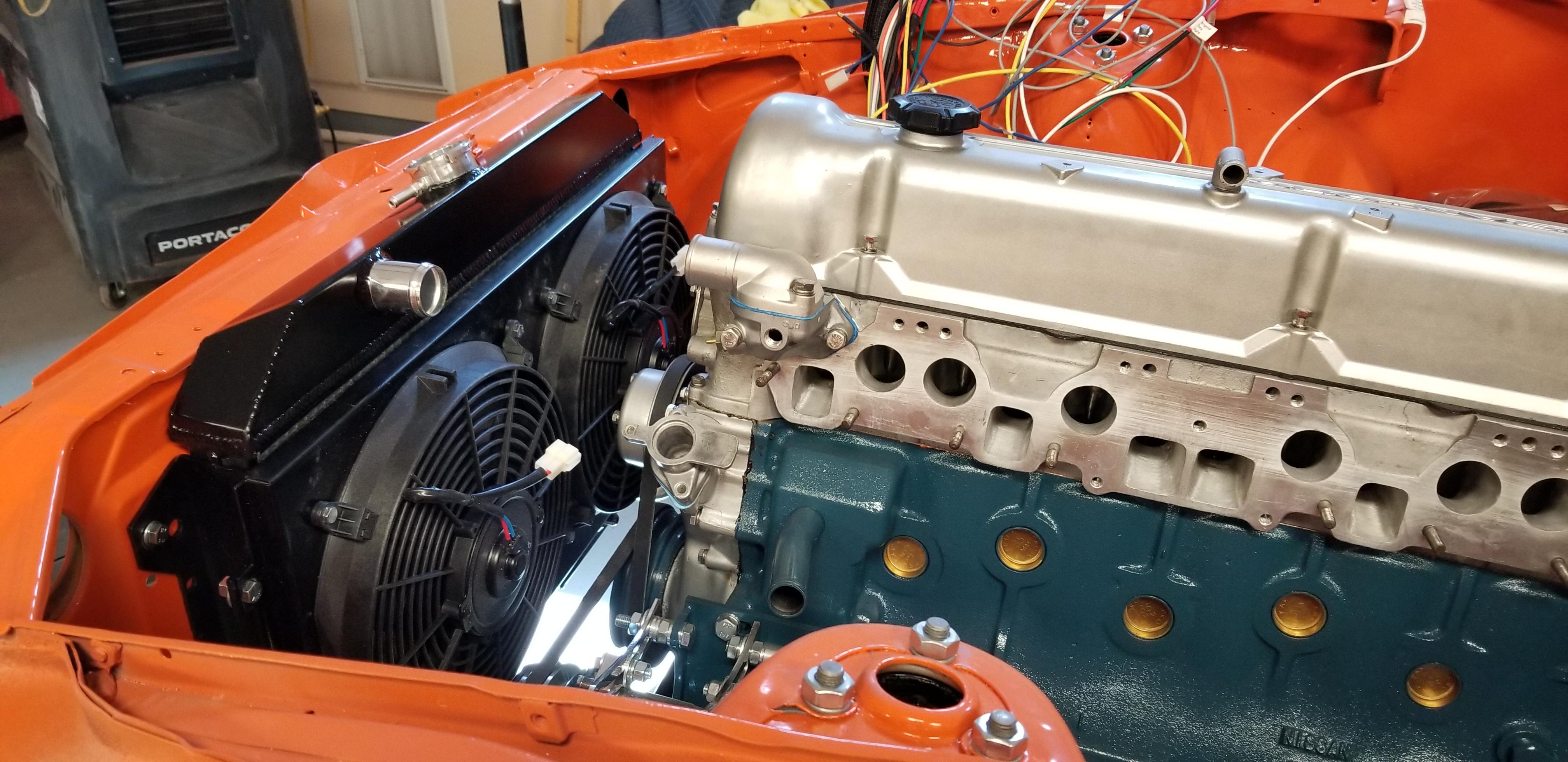
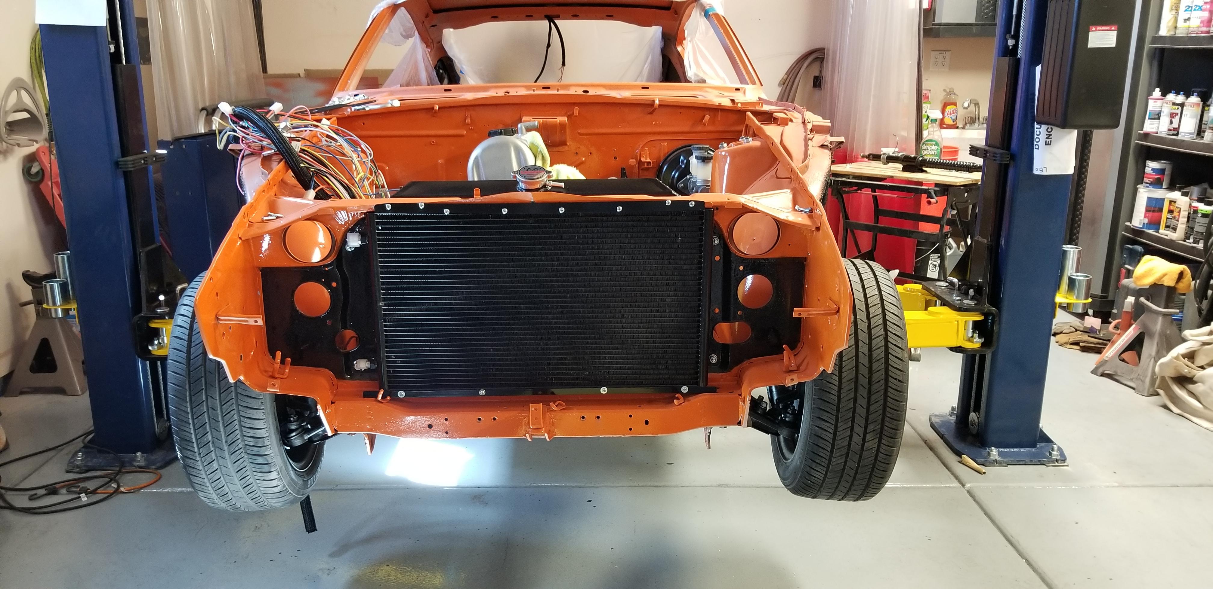
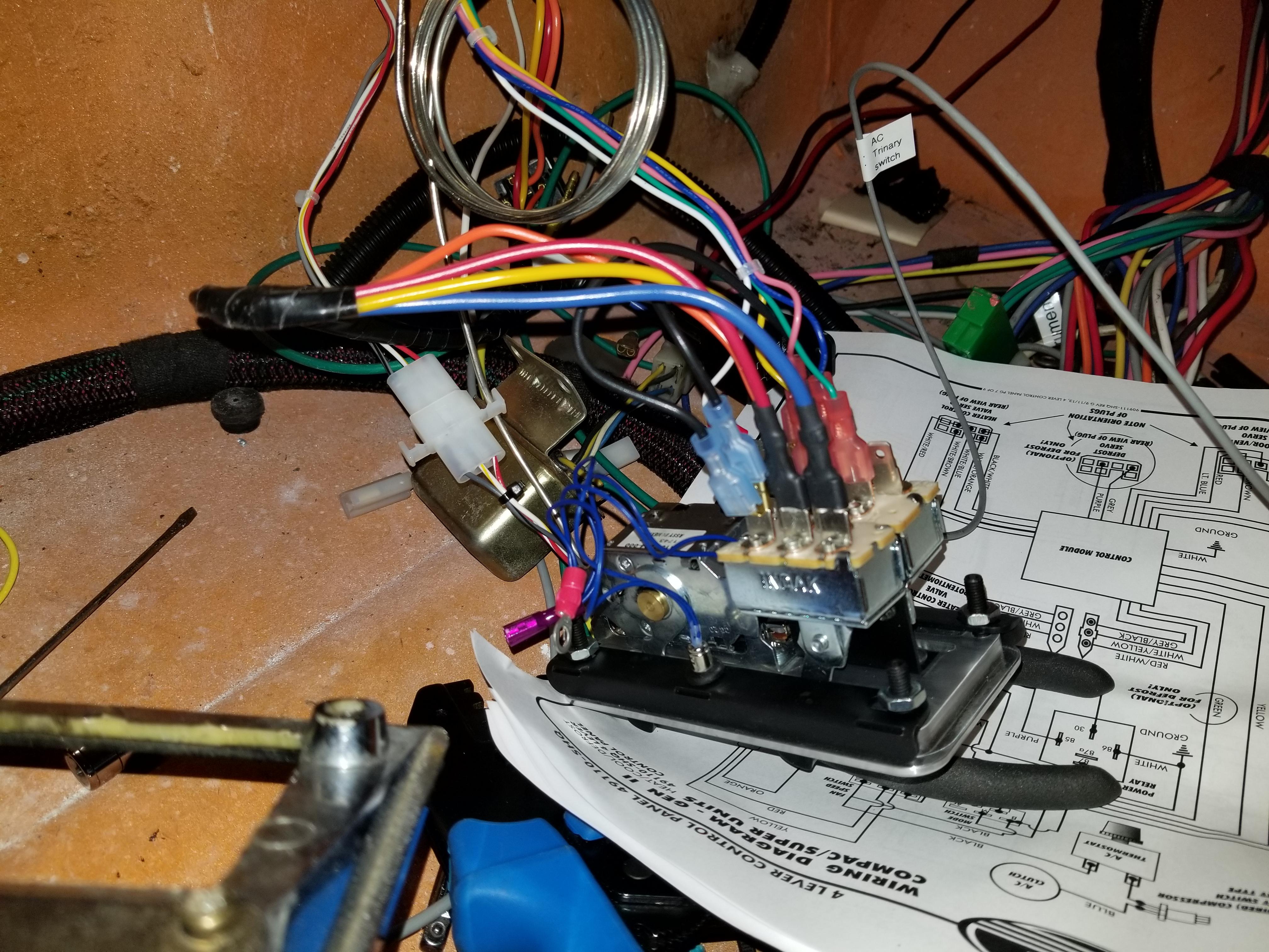
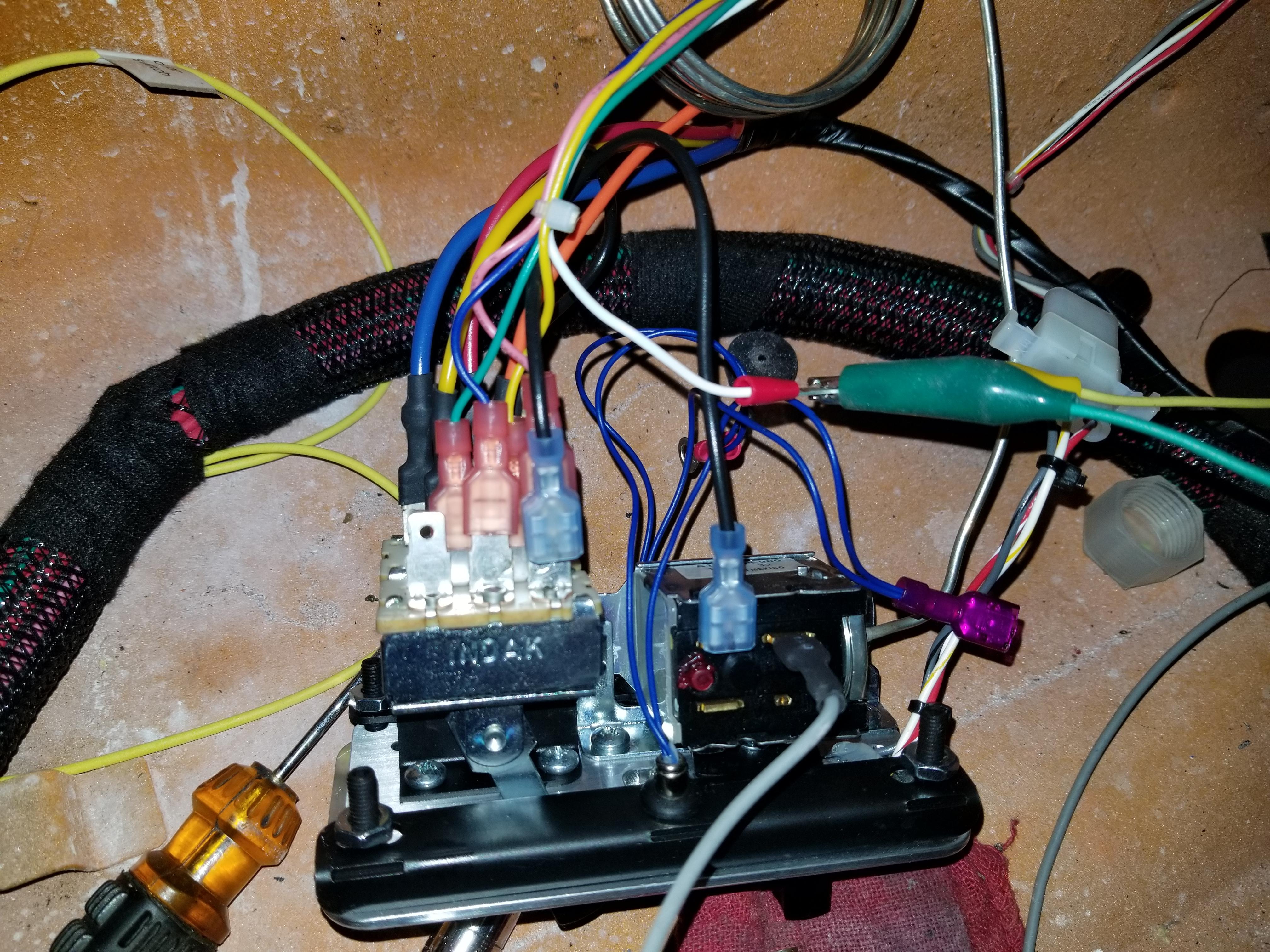
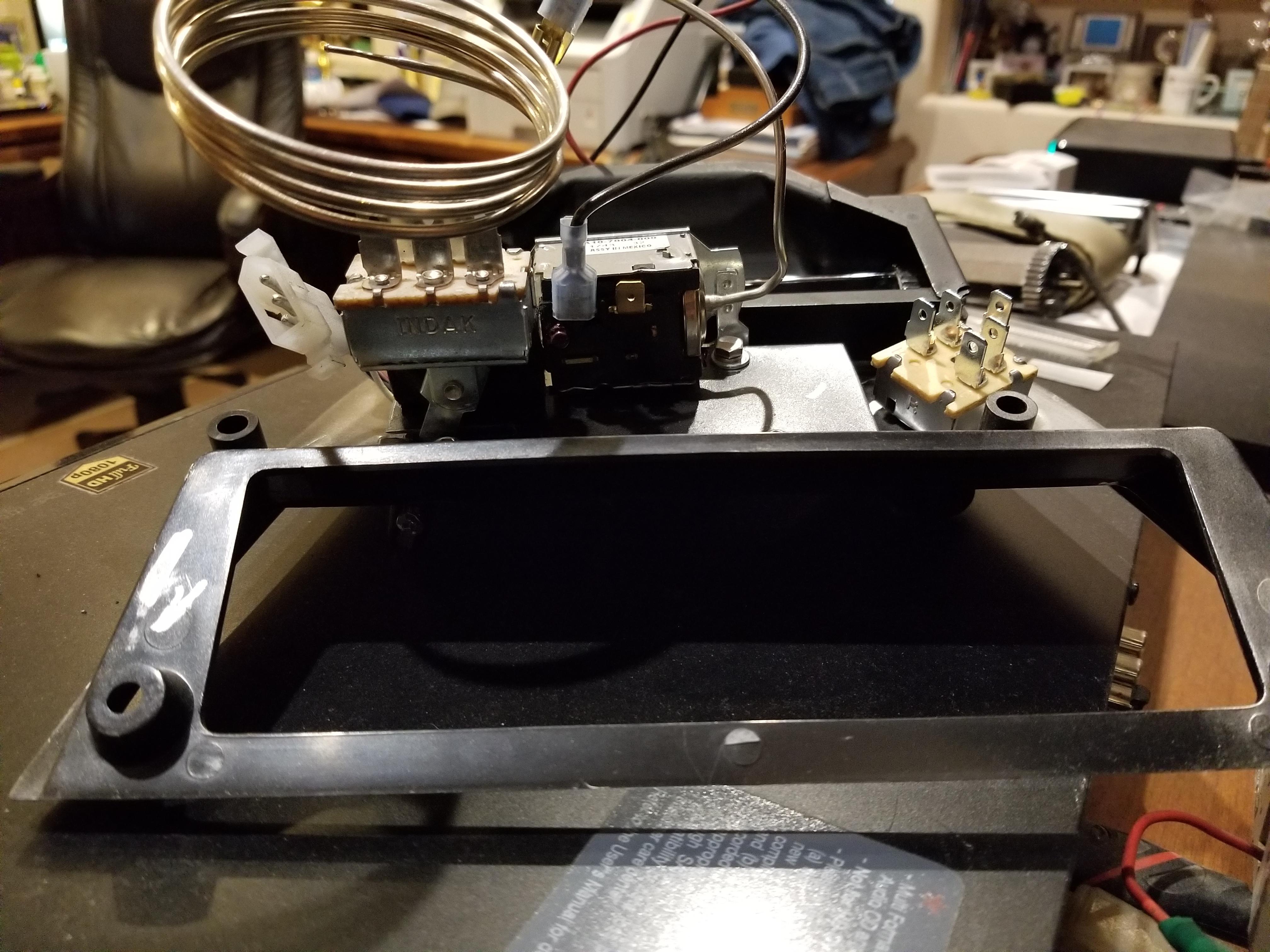
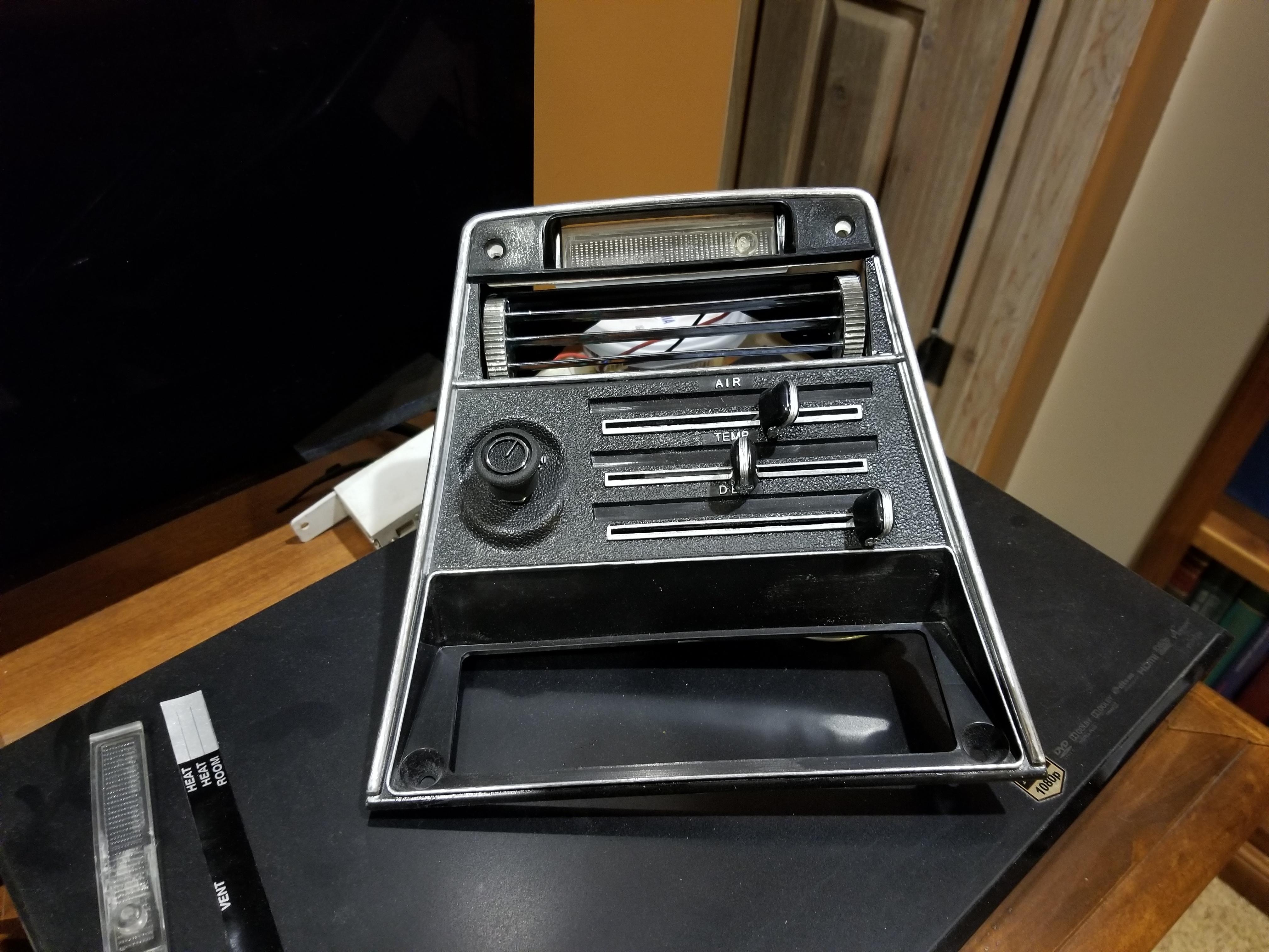
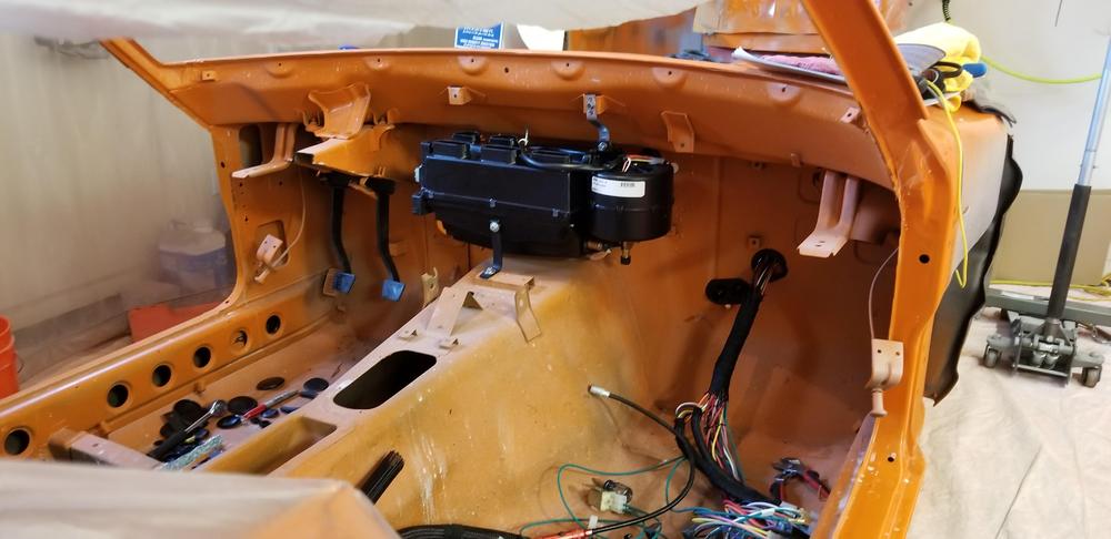
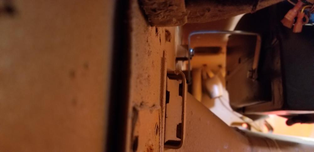
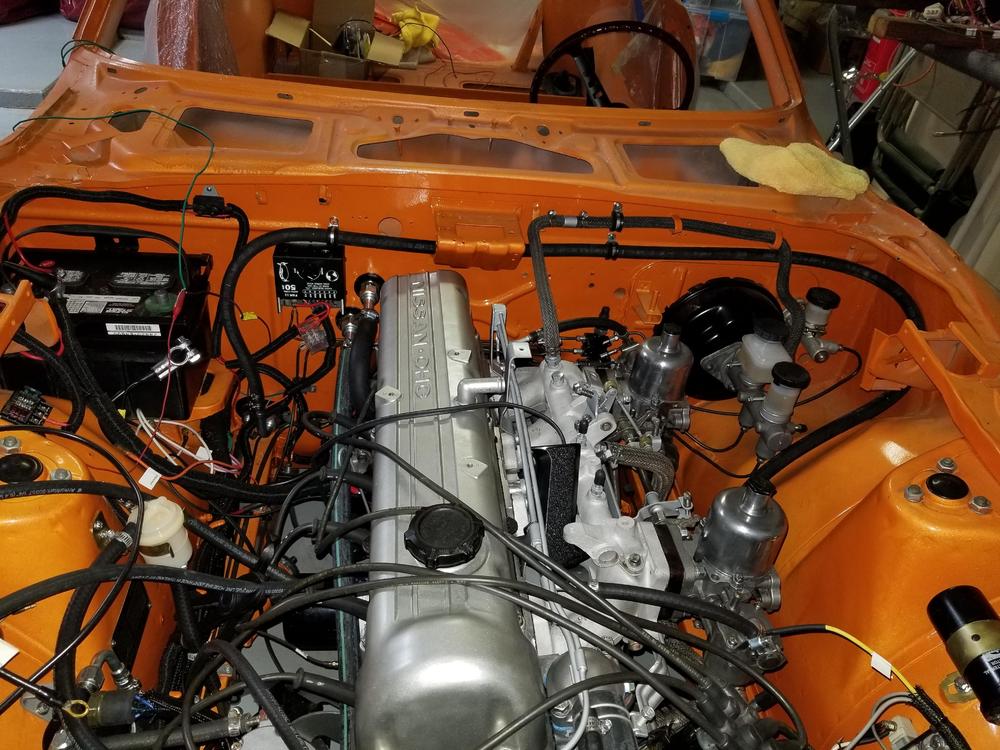
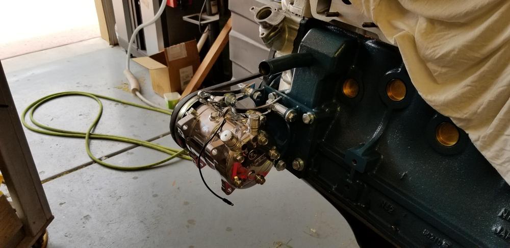
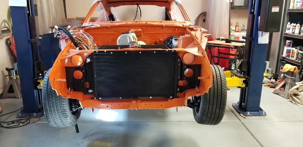
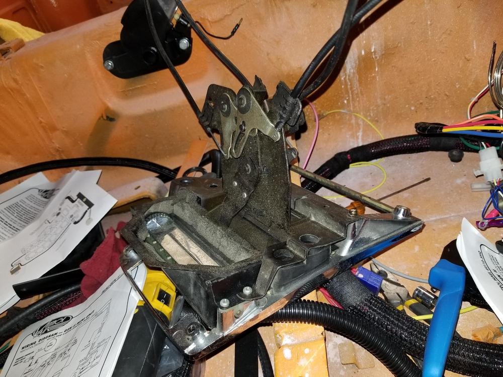
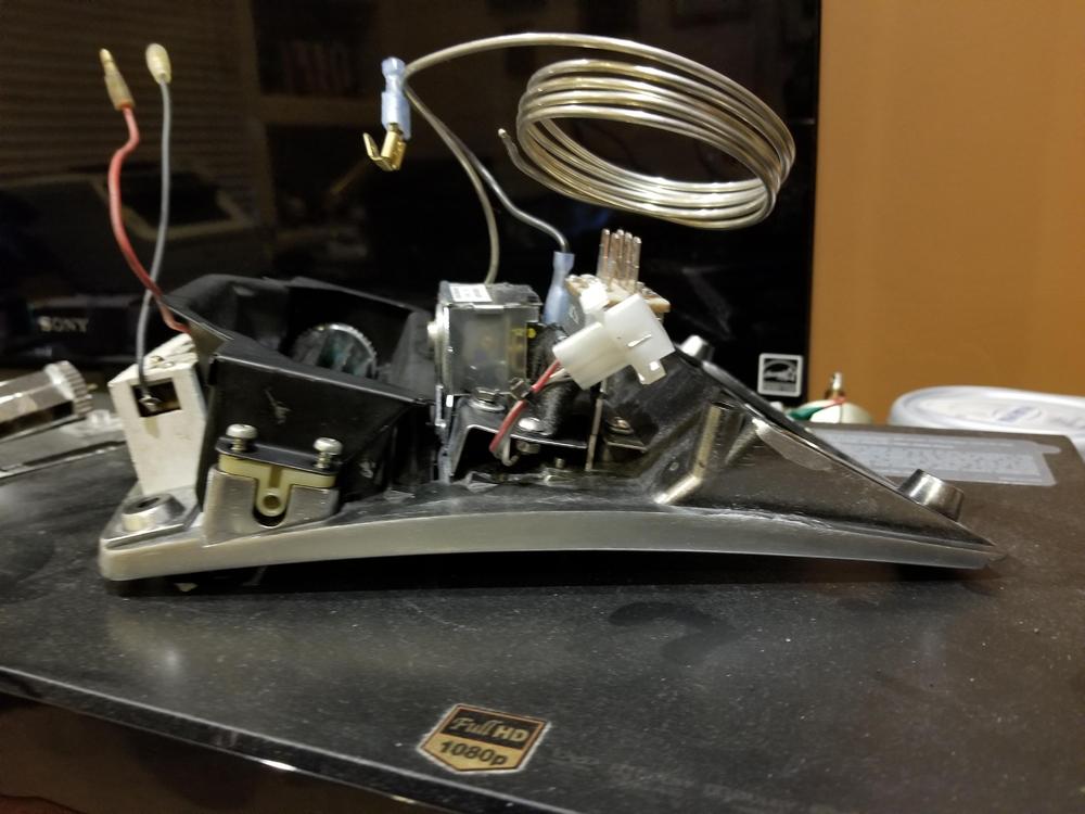
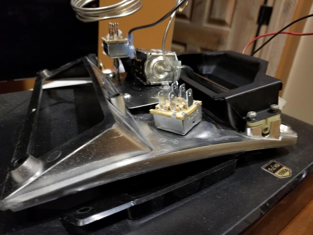
This forum has been very helpful to me. As a means of documenting some of what we have done and to help others avoid some of my mistakes I thought I would post the installation of a vintage gen II mini AC system. Background: My son and I are restoring a 1973 240z. We call it the bucket, as there was a significant amount of rust that had to be dealt with and our other choice – Money Pit was already taken. We are changing the color from 113 avocado green to mango orange, it has an L-28 engine and a 5 speed gear box. At this point: the car was taken to bare metal, metal replaced where required and any rust has been eliminated the rear clip is painted, front and rear suspension has been restored/upgraded and installed brake system has been restored/upgraded and installed half axles, differential, driveshaft, transmission, engine have been restored/upgraded and installed fuel system has been restored and is installed cooling system has been restored/upgraded and installed electrical harness has been restored/upgraded and the cockpit harness is installed When we purchased the car, it did have a non-working aftermarket AC system, probably installed at the dealership. We decided to replace the AC, defrost, and heater with an integrated system from Vintage Air. Vintage Air recommended a Gen II Mini The Gen II is a replacement for the original heater core, air box, and under-dash AC evap. As you can imagine the gen ii is quite a bit smaller than the original components, but it is a universal system and therefore it needs to be shoe horned into a space under the original dash. Because I removed so much original material, I thought that I would be able to fit the combination evaporator/heater and air box above the transmission tunnel and behind the instrument panel. This gets it away from the passenger footwell and centers the defrost and climate openings. I found someone that had done something similar so I was fairly confident that I would not have a fitment issue with the dash. Brackets are provided with the Gen II but I did not find them to be particularly useful. Mounting is fairly straightforward, but if you are like me sometimes it takes a few proto-types to get something that satisfies you. Mounting the Evaporator Once the evaporator is in place you can decide where hoses need to enter/exit the firewall. It is always nice to use the original holes, but you need to consider the radius of the bends for the hoses as they do not like to make sharp turns. I decided to install bulkheads for both the AC hoses and the heater hoses. I like this luxury because if the engine has to come out or if anything goes wrong with the evaporator/heater then disassembly stops at the firewall. Also if any of the hoses fail you don’t have to disconnect at the evaporator to replace an engine bay hose and vice versa. Working these stiff hoses and close connections under the dash is not the most comfortable task, The only downside that I can think of regarding bulkhead connections is that there are additional breaks in the hoses that now require some sort of mechanical connection and this is yet another opportunity for a leak. I did not have to cut any additional holes in the firewall but I would recommend that you buy individual bulkhead connectors as opposed to 2-way or 4-way bulkheads. This probably makes it easier to use the original holes. Bulkhead Connections water connections are behind the evap, compressor connections are near the main harness entry. Those are EZ-coils fitted on the hoses to help keep them from collapsing due to a sharp radius you can see the water connections on the passenger side of the engine just below the level of the valve cover. Compressor lines enter the bay just above the passenger frame rail. I would have preferred to do all of the hose routing with the engine out of the way, but I was concerned that I could not visualize every aspect. The AC compressor is a bit of a chore to mount so I will do that while the engine is on a stand. Here is what is being replaced – a Nissan bracket, and a sanden compressor. The original compressor is much lighter than most that were used in the day like York, but the original combination still weighs 24 lbs. Original Bracket and Compressor I tried to use the original bracket. Even though it is heavy and bulky it is clearly better because the compressor can be mounted so that it does not have to move to install a v-belt. There is an integral idler pulley that is adjustable. I spent valuable time cleaning the bracket and the pulley in preparation for painting, but alas I could not figure out a good way to modify it to accept the new compressor and properly align it with the engine pulley. The bracket that I purchased from Vintage is simple (no idler pulley) but it is made to convert a York bracket. Unfortunately, it does not line up with the bucket’s pulley. So my choices were to somehow modify the simple bracket or build a new bracket. I decided to attempt a mechanical solution as opposed to modifying the bracket by welding a piece on. The problem really has two pieces: the compressor must align with the engine pulley and because there is no Idler pulley it must rotate to install and adjust the v-belt. Here is what I came up with. It is 9lbs lighter. I will continue to look for a more elegant solution with an idler pulley, but I need to get the engine back in the car. NEW AC Bracket and Compressor With the engine and radiator in place it is an easy task to route the Compressor hoses to the bulkhead. Vintage offers a connect system called “easy clip”. I have not used this before but it allows me to construct all of the hoses myself without the usual expense of a crimping tool. This will make start-up of the AC system much simpler, because I will be able to go to a shop and only require evacuation, drying and filling to get the system working. This should take about an hour as opposed to waiting for someone to construct the crimp hoses and depend on someone else to route the hoses to my satisfaction. Hopefully, the easy clip system works well and does not leak. Condenser The condenser and drier were both part of the gen II kit. Bracketing the condenser was fairly easy. You need to take into account the holes in the radiator support as the hose that sources the drier must go through the support. It would have been nice to mount the drier ahead of the support where the air is coolest but it was more convenient for me to put it on the engine side. I converted to an aluminum radiator with an electric fan so I installed a trinary switch on the drier. So, the routing of the hoses is: Evap to Comp, Comp to condenser, condenser to drier and drier back to the evap. The route that I took was evap across the firewall to the comp mounted driver side low, from the compressor thru the radiator support across the condenser to a connection on the passenger side of the condenser from the condenser thru the radiator support to the drier, from the drier along the passenger frame rail to the firewall to the evap. That is a 2 row aluminum radiator painted black with a dual electric fan setup. I still think that it is strange to use a 2 row, but based on what I read I convinced myself that 2 rows were actually better than 3 or 4 for the same overall length and width. The condenser is visible here - in front of the radiator Climate Control Panel The last piece of the puzzle – mounting the controls. When this project began, I had no idea what I was going to do with regard to the climate control panel. Trust me this restoration has had enough challenges, but I wanted the controls to look they were part of the car. Originally, I envisioned the new panel hidden behind the original panel with mechanical linkages to control the system. I ordered a panel from vintage air, their least expensive. It allows for 4 slide type controls: AC compressor on/off combined with AC temperature control, Heater temperature control, Fan speed control, and Mode (defrost, feet, body, body+feet) control. Now that I have good handle on the mounting of the evaporator and know that the dash will fit without interfering with the evap I can consider using the original Datsun climate control panel which had the original mechanical controls for the vent, heater and defroster. The bucket had an aftermarket AC system, but it did not have anything integrated so the compressor control and the AC temperature control were all hung external to the dash. The Datsun climate control panel accommodates three slide controls: outside air, heater temperature, mode (defrost, feet, body, body+feet) control; and a rotary fan speed control. The controls for the original AC system were appended to the dash and did not compliment the look and feel of the car. The original climate control panel and the vintage air panel I decided that I was going to attempt to integrate the vintage air controls into the 240z panel. My control panel was not in very good shape so I decided to use it to trial fit everything. I opted for the luxury of replacing my panel with a new one. MSA does make one – it’s approximately $130. Its plastic, well built, but nothing special. They have a slightly more expensive version with chrome accents – I was not smart enough to order that version, so I spent more to have the fun of trying to do chrome accents myself. The first obvious difference between the original and the vintage controls is the fan control. I ordered a rotary fan switch from vintage air to replace the slider that I originally purchased. The hole in the 240z panel must be opened a bit to accommodate the vintage air control. If you go this route, remember to be careful as you are working with plastic, so cracking is a real possibility. Next, I removed each of the slide switches from the vintage air panel. In my opinion the best/easiest way to integrate them into the 240z panel was to create an intermediate metal panel to house the vintage air controls and then mount the intermediate panel onto the 240z plastic panel. The metal panel should help distribute the forces of the sliders and will allow me to more easily position the sliders where I need them. It’s not as easy as it sounds. The travel of the vintage air sliders is quite a bit smaller than the original 240z controls. I considered mounting the sliders a few inches back from the 240z panel which would make the slider travel more similar to the original but it complicated everything else so I rejected the idea. The length of the vintage air slider mechanisms is also different than the original 240z controls. The vintage air heater temperature control is a bit hooky in my opinion. It is mounted to the vintage air panel by being squeezed by their bracket. There is no provision to screw it to a panel. It’s quite small. I used thin aluminum sheet stock to build trial configurations. It’s easy to bend and easy to cut and you can expose a lot of issues very quickly by using a proto-typing process. The AC control is relatively large. I decided to fit it into the top slot of the plastic panel labeled “AIR”. In my opinion - this is where it fits best. You can mount it without a lot of difficulty with one exception – the length of the slide control is too short. If you choose to go this route don’t purchase the vintage air panel (it’s a waste of money), and when you order the controls make sure that they provide full length sliders. When they build a kit with their panel, they cut the sliders to fit their panel and it is too short for the Datsun panel. I very carefully bent the L shaped bracket flat. I then removed enough material from the bracket to allow the slider to protrude through the plastic panel enough so that I could attach a plastic knob to it. I wanted to use the original 240z knobs to help disguise the vintage air system. One of my knobs was cracked and so I searched for a replacement. I found some new ones at Banzai Motor Works that were reasonable. The heater temperature control will fit just below the AC control. I built a small aluminum bracket that pinches the heater control and attaches to the climate control panel. Lateral movement of the heater control is prevented by the aluminum bracket and vertical movement is prohibited because the heater control is held in place by the ac control above it. The mode control will fit in the climate control panel’s third (lowest) slot. Here is an image of the original control panel with all of the controls mounted to it. Also, you need to seal off the cowl vent because there is no provision for the vintage air system to utilize that vent. The only fresh air vent system that you will have will come from the vents on the driver and passenger side which are controlled by individual mechanical cables. These vents actually get their air thru the ducts to the opening in the radiator support. The bottom line is that the original 240Z panel will remain in-tact and the new system will seamlessly fit behind it. You will not be able to tell that the entire climate system has been upgraded. vintage air controls Integrated Panel CONCLUSION If you choose to upgrade your AC system and you opt to integrate the controls into the original climate control panel you can benefit from my mistakes. Do not order the panel/control kit. Instead order the individual switches with full length sliders. Make sure that you order the rotary fan control and not the slide fan control switch. In the spirit of full disclosure I have not fired-up the AC system yet. Having said that, based on previous experience I believe that Vintage Air has done a great job providing a terrific system with more than adequate documentation. I especially like the reduction in physical size and weight. I also like the electronic controls as opposed to mechanical – cable stretch and loose cable connections are a thing of the past. I appreciated being able to make my own compressor hoses (hope they are solid and do not leak). I do wish that they would come up with a universal compressor mount with an idler pulley. All in all, it is a great system. It takes a fair amount of time and effort to install, but I believe you will be happy with the result. I will try to answer any questions that you might have. Good Luck.


-
Siteunseen - this is great. Thanks for taking the time to help. I appreciate it. AND, definitely no texture. CantechZ - if you're out there - thank you as well.
-
The car is a 1973 240z. I am restoring the 3 piece steel rear tail light panel. I was simply going to paint in what supposedly is the correct dark grey color, but someone with fair amount of experience supplying parts for these cars told me that the finish was actually lightly textured. Can anyone confirm this for me. If it is true then my plan is to prime the panel and with little more than a dust coat spray a textured paint (color is not correct) over the primer. This would be followed by two coats to cover with the period correct color. I would like to protect with a matte clear, but I am not sure if it will result in a finish that is too glossy or if it would reduce the texture feel to non-existent. Would appreciate any insight or advice. Thanks.
-
First of all thanks for the quick responses. Captain Obvious, I was pulling fuel from one jerry can and had the return line connected and emptying into a second jerry can. Both of you are correct I am missing the restrictor on the return line. As it turns out the stock restrictor is quite small which would only allow for a very small trickle being returned to the tank. I have a choice I can either replace the fuel rail, or build a restrictor for the end of the rail that I have. I think I have an old jet that might work. This will certainly cut down on the volume of fuel being returned to the tank. If it is still too much then I can always replace the fuel rail with a used one. Zed Head - thanks for taking the time to post the test procedure. Like you I thought that the fuel pump has some relief mechanism that would be triggered by sufficient back pressure and cause the pump to stop sucking gas from the tank. I have been told that there is no distinct pressure relief. As I understand it when back pressure is higher than the 3-4 lbs the mechanical pump simply can't overcome the back pressure, but the pump continues to try to suck fuel into the rail; it just will not succeed until the back pressure is lower than the output of the pump. The end of the return line continuously weeps fuel and if the pressure in the fuel rail decreases below 3-4 lbs then the mechanical pump can push more into the rail. Once again thanks for the help and the education. Regards, ron
-
I am in the process of restoring a 1973 240z. It is powered by an L28 (twin 3 screw round top SU) with a 5 speed gear box. The engine has been completely rebuilt and is now back in the car. I was in the process of refinishing various parts including the fuel filler and cap so I did not want to use the fuel tank as a source. Instead I supplied fuel from a 2 gallon jerry can, I do not know precisely how much fuel was in the can. Thankfully the engine started almost immediately. As you know there is some fiddling to be done when you don’t have an electrical harness and your remote starting while trying to adjust carbs and timing. Well, it was really a very short time before I was out of gas. Now if the car was running badly that would be one thing, but it wasn’t, it actually was running fairly smooth. Never the less I was out of gas. Okay, so I go down and get 2 more gallons. I removed a plug and it was not sooty and had no smell so the mixture could not have been too rich. I ran the engine again but ran out of gas much sooner than I expected. The fuel inlet line is a hardline that is U shaped with ports that connect each carb via a rubber hose and terminates with a rubber hose to the hardline that returns to the fuel tank. This connection was in place and there was no sign of fuel leakage in the car, or under the car. I decided to take the return line to a second jerry can. Another two gallons. A huge amount of gas was being sucked out of the jerry can with the gas and a huge amount was being deposited into the return jerry can. The amounts were not accurately measured but it seemed like at least 50% of the gas was being returned. Sorry for taking the long way around, but here’s my question: Is this normal behavior? I am running a mechanical fuel pump. It is new. The SUs have been rebuilt and are working quite well. The fuel lines are either new or clear. The fuel filter is new. Is the mechanical fuel pump supplying more gal/min than it should? Because of the physics of the setup I don’t think that the mechanical fuel pump is supposed to respond to pressure caused by the float bowls becoming full and the needle valves shutting the inlet to the bowl. The carbs are not leaking. I would appreciate any insight that you might have. Thank you.
-
I learn something everyday - thanks. Hope you found a spacer for yourself.
-
Done deal. Once again thanks for the help. Like you I thought that one of the purposes of the spacer was for thermal insulation. But, someone pointed out that the bolts go directly from the pump into the head, so I have come around to thinking that the primary purpose is to properly space the pump from the eccentric. Once again very nice of you to help out. regards, ron
-
Thanks for responding. Appreciate the explanation on the two bolt vs. the three bolt - thank you. I've searched the web and also have been checking Rock auto, they continue to show out of stock. Beck Arnley discontinued the part. If you can spare one I would really appreciate it - thank you. I will send you a message with contact info. Someone in mexico is selling the two bolt, 4 cylinder version, but I have not found anyone that is building these. I have seen threads where folks have written about aluminum version but have not found any info to order one.
-
I need a mechanical fuel pump spacer. There are two types that I know of a (2) bolt hole and a (3) bolt hole. I need the (3) bolt hole. It is made from the same material that is used for the thermal insulators between the intake manifold and an SU carburetor. Thanks for your assistance.
-
The front valence valence consists of three pieces: left, right and center. Unfortunately this valence is specific to a 1973 240Z