


240260280
Member
-
Joined
-
Last visited
Everything posted by 240260280
-
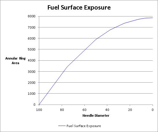
 I think the vacuum method is important as it can be replicated on a test bench. One can wet-flow water safely on the bench with the reference needle and old carb then replace against the modified needle as it is worked to measure differences in fuel flow for each station(vacuum reference). As mentioned, CO and I talked about these methods many years ago Another method is to have non-tapered needles of different diameters then drive with these to map a/f against rpm and vacuum. This will work nicely for optimizing the higher stations of idle and cruise. Again... this was from many moons ago. Note that each straight needle will suck in most load/rpms except for some sweet spots so the goal would be to find these sweet spot stations and assign the diameter of the test needle to these.
 -
Camera or measure vacuum from nipple drilled into top of plastic plunger .....remember our discussion many moons ago of mapping vacuum in carb dome against load and rpm then replicating on a flow bench to "find station"? We have been there and almost done that https://www.youtube.com/watch?v=i2I5QKDDEDc Another:
-
This may be helpful. (no units). You will need to map air flow at rpm to vacuum then map vacuum against needle height (annular ring exposure) for various throttle openings. Then map the fuel flow from exposure and vacuum.
-
Putting wheels at joint helps.
-
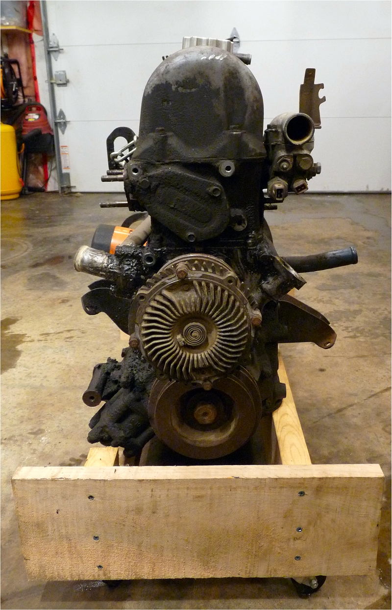
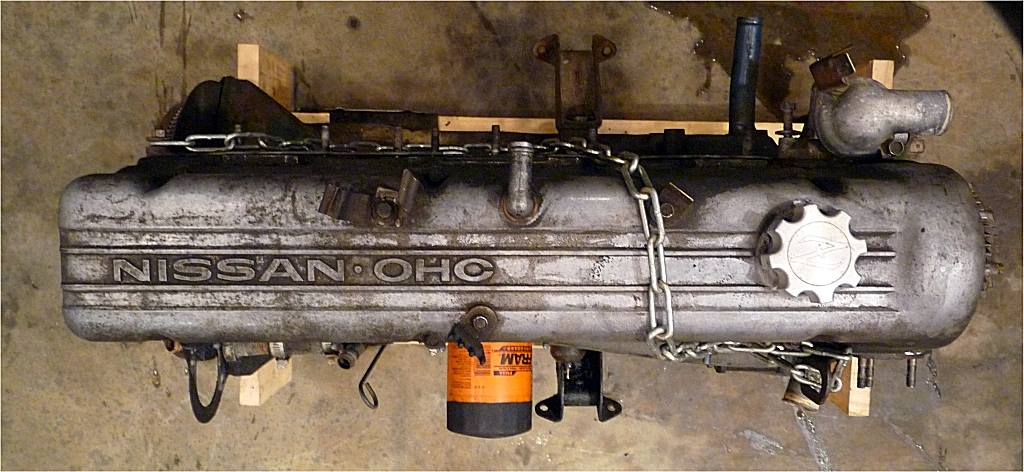
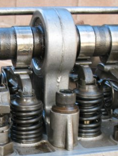
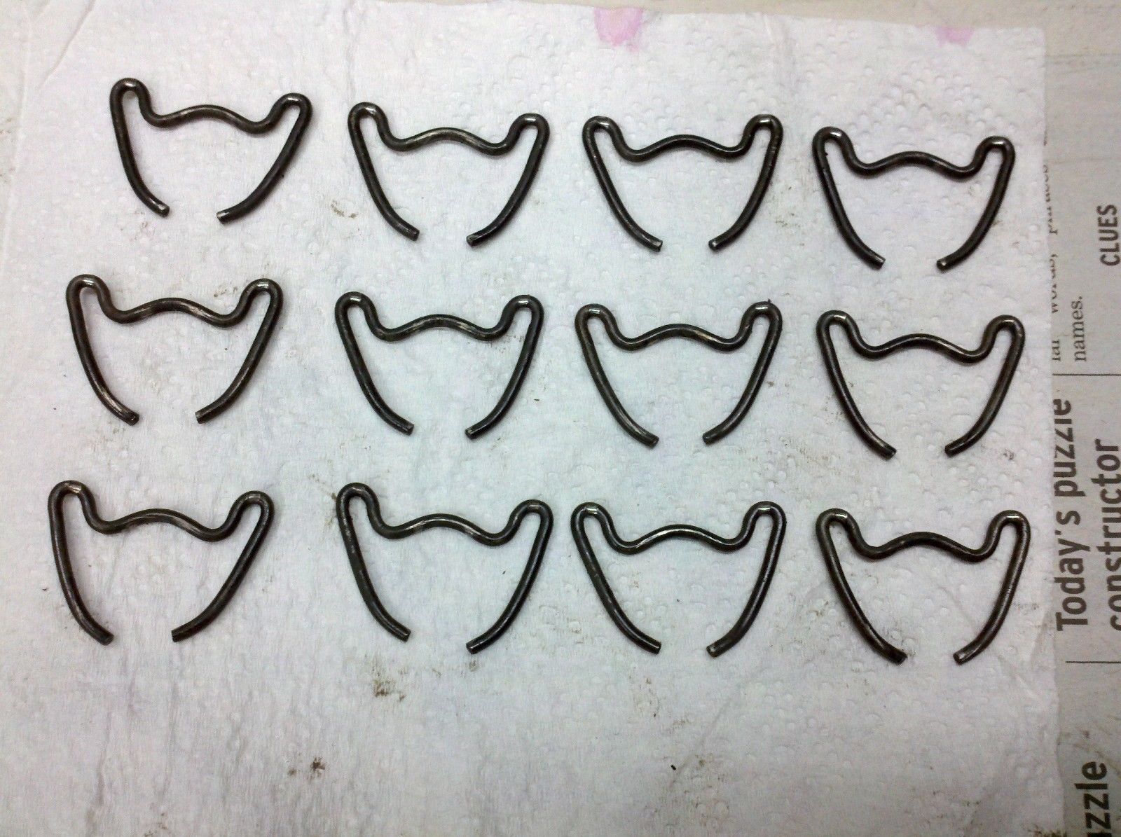
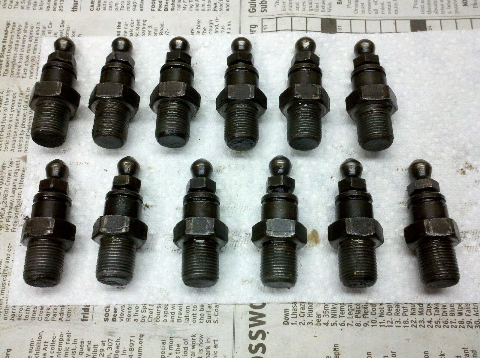
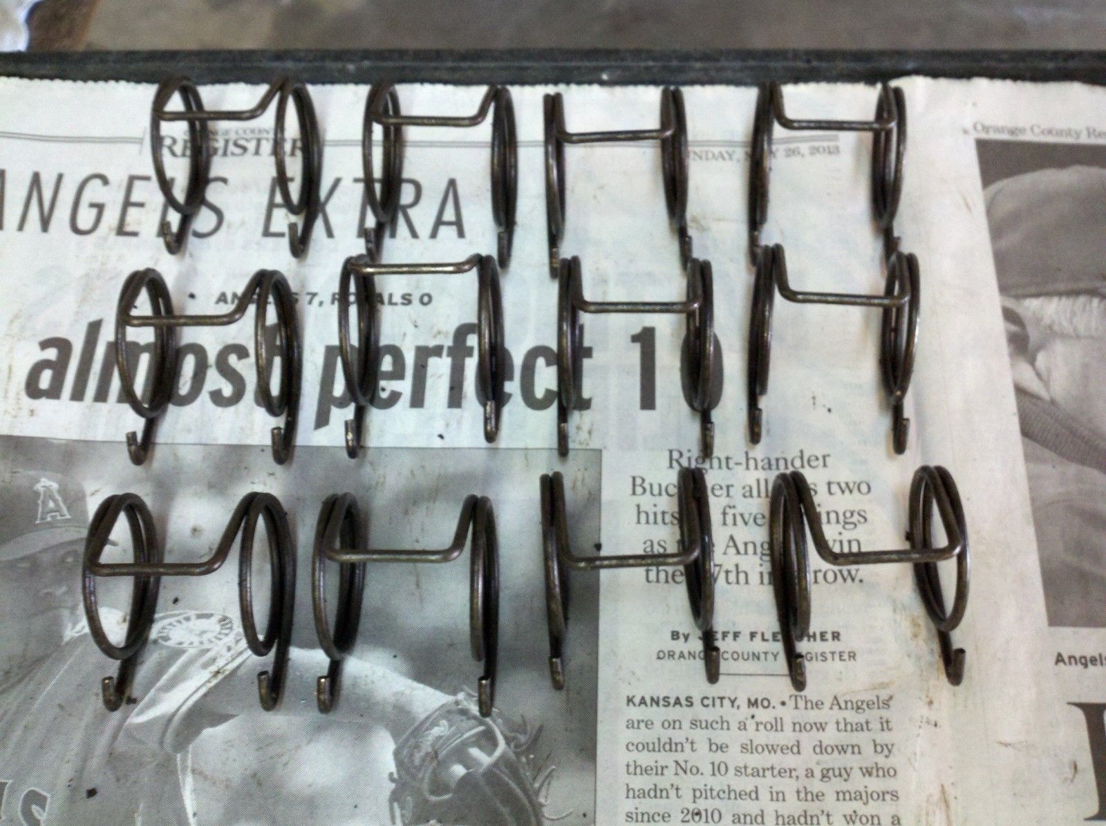
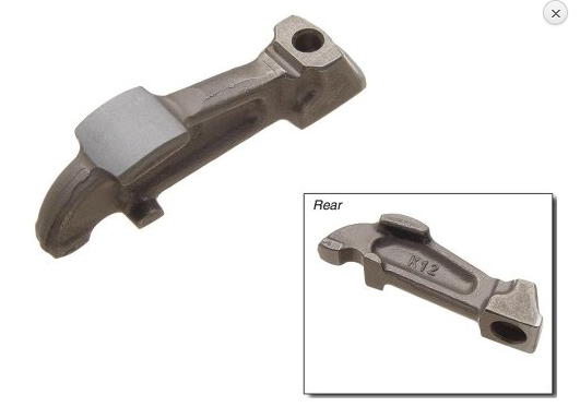
In design, there are similarities, and then there are nearly identical copies. One occurs from convergent evolution, the other occurs from licensing, from disregard for licensing, or from expired patents. I don't know the history of these parts but they are all nearly identical so I assume they occurred via Prince's licenses. Regardless, our engines have too much in common with these early vintage MB's to be ignored; rather, I think, it should be proclaimed.
-
I like this compact design: https://www.ebay.com/itm/Datsun-240Z-Abarth-endsilencer-NOS-2-5-exhaust-system/222734995837?fits=Model%3A240Z&hash=item33dc0a517d:g:JnYAAOSwc~laFu7r&vxp=mtr
-
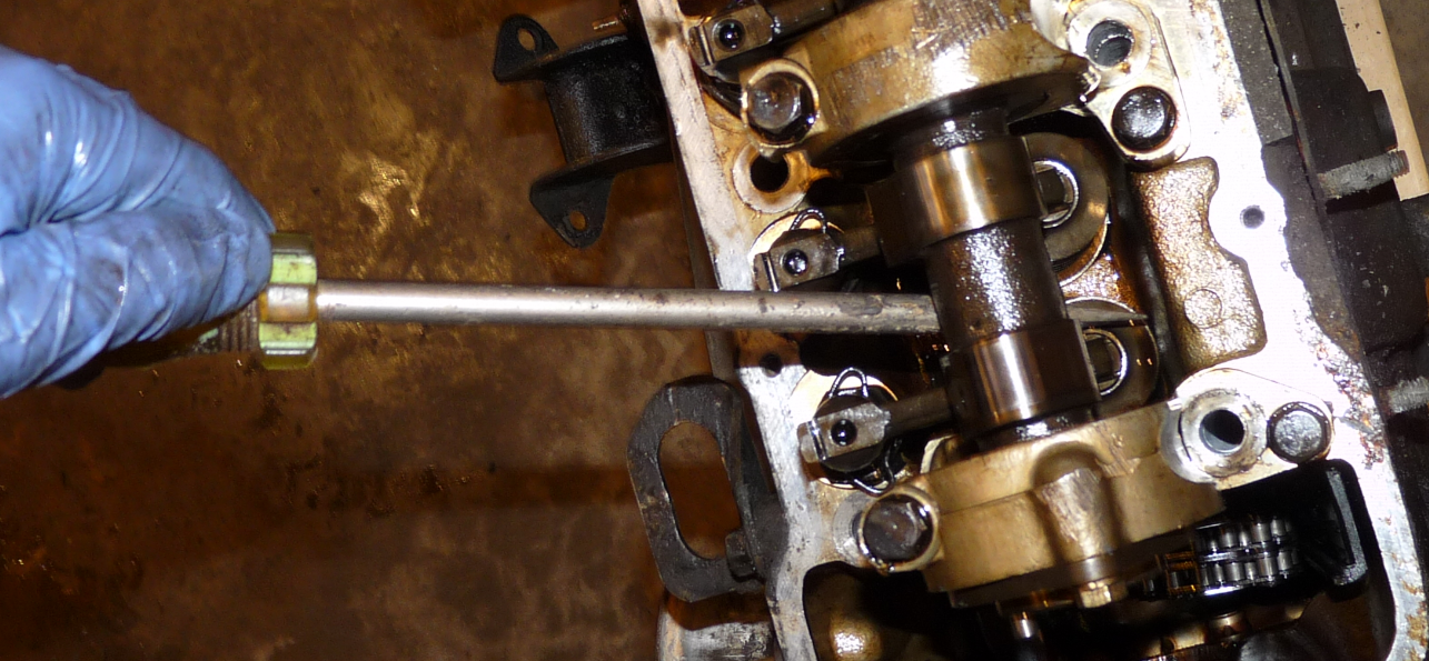
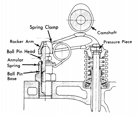
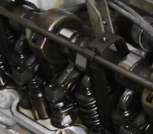
Here is a photo of how to pry valve down so that you can slide rocker in place or out:
 These early Mercs do not seem to have the locking nut like on the Z's
Some of the Merc's are 14 mm and some are 17mm go figure https://mercedessource.com/store/m130-m180-special-valve-adjustment-17mm-socket-wrench
14mm and 17mm are the L series sizes. I'll try and find out what the M-180 uses.
First M-180 was built in 1946:
These early Mercs do not seem to have the locking nut like on the Z's
Some of the Merc's are 14 mm and some are 17mm go figure https://mercedessource.com/store/m130-m180-special-valve-adjustment-17mm-socket-wrench
14mm and 17mm are the L series sizes. I'll try and find out what the M-180 uses.
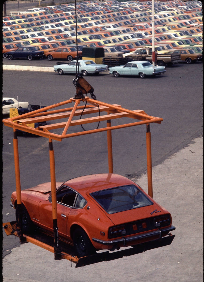
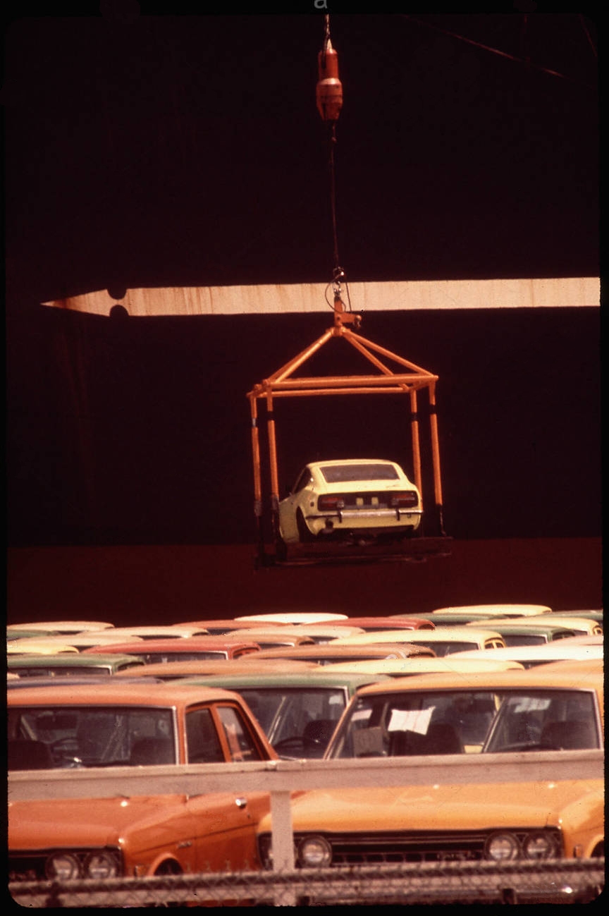
First M-180 was built in 1946: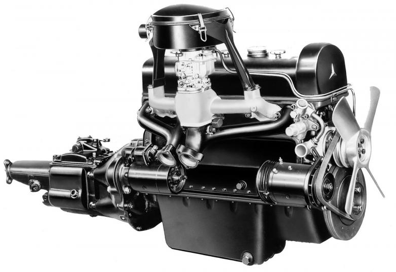 Spot on Steve & Fred! The photo was taken in May 1972!
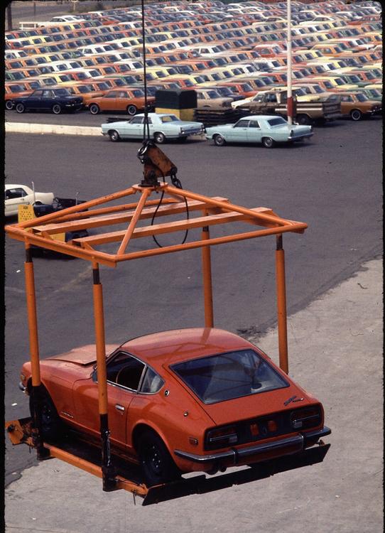 I don't think it was copying but it is irrefutable, from the above components and configuration, that the Nissan/Prince L engine has its roots clearly in the Mercedes M-180 engine from 1951. Gents and Gals, we have a next generation "Vintage-Mercedes-Based" engine in our Z's.
btw do you see similarities with anything?
Close. 250SE was in 1965. The parts are from an engine released 14 years earlier.
Nope.
Not a Nissan.
New respect for tires after this:
The rocket scientist Zedyone_kenobi gave us a great design. I am using 3 in my garage: Here is Zedy's
I don't think it was copying but it is irrefutable, from the above components and configuration, that the Nissan/Prince L engine has its roots clearly in the Mercedes M-180 engine from 1951. Gents and Gals, we have a next generation "Vintage-Mercedes-Based" engine in our Z's.
btw do you see similarities with anything?
Close. 250SE was in 1965. The parts are from an engine released 14 years earlier.
Nope.
Not a Nissan.
New respect for tires after this:
The rocket scientist Zedyone_kenobi gave us a great design. I am using 3 in my garage: Here is Zedy's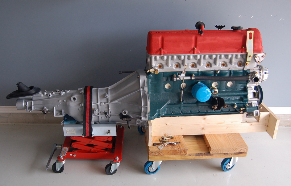


Important Information
By using this site, you agree to our Privacy Policy and Guidelines. We have placed cookies on your device to help make this website better. You can adjust your cookie settings, otherwise we'll assume you're okay to continue.