240zadmire
Free Member
-
Joined
-
Last visited
Everything posted by 240zadmire
-
I’m more inclined to do the brazing. But who knows, some one on this forum might have a very good result with sealing too. I need to do more research, by research, I mean watch more YouTube, to learn how to braze. Of course it will be off the car or at lease zero pressure before I do it.
-
This is how I fixed mine.
-
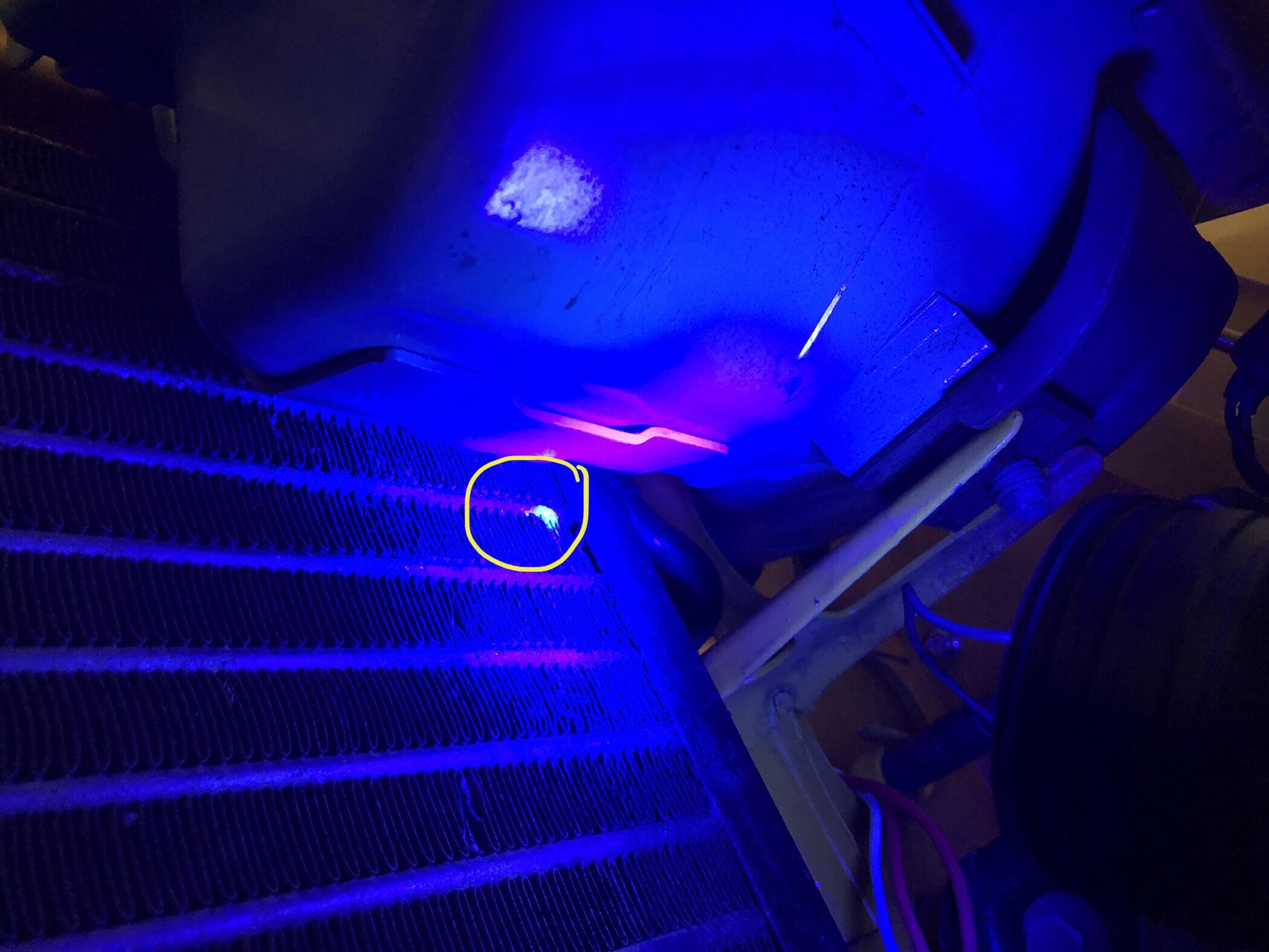
Well, it was good for couple of months. Found 2 other leaks. One is on the back side of the compressor. This will need a big o-ring and disassemble the compressor to fix. The other is at the condenser. Must have been a giant bee with a steel stinger that poked a hole. have anyone try the Red Angel A/C seal? What about using MAP gas to blaze the leak at the condenser? regards

-
Isn’t the Teflon tape insulate the sending unit’s ground connection?
-
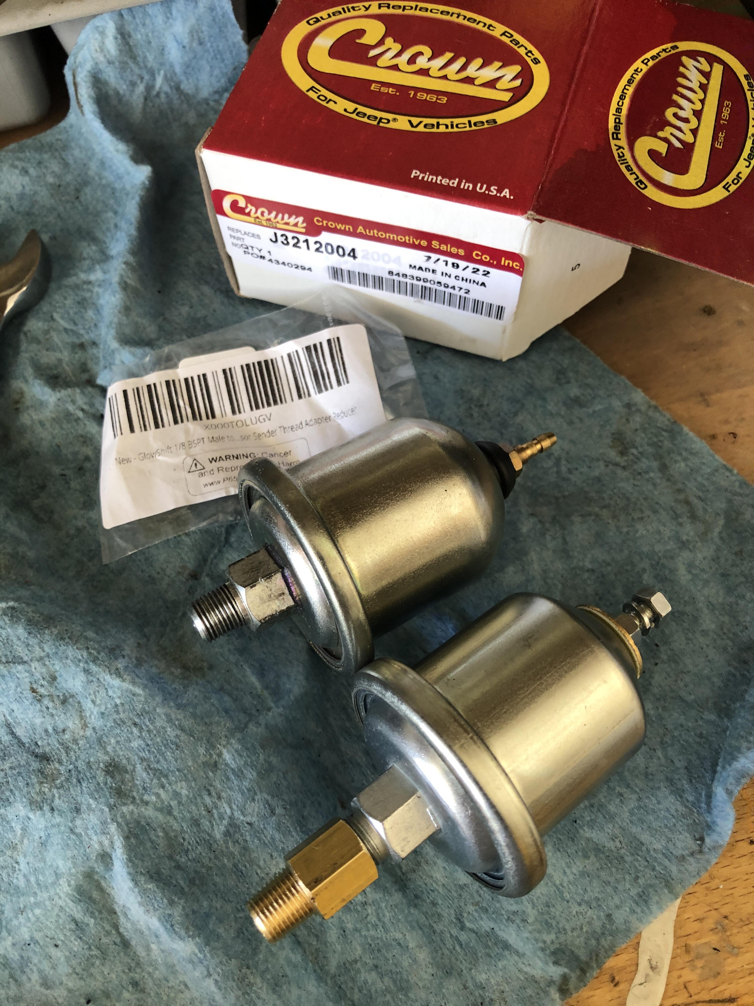
it's 1/8 BSPT threading.
-
When all other suggestions checked out and issue still exist, and if $20 is affordable, I would rebalance them again. Mine tires were couple of thousand miles. I swapped the tires to the mag wheels. Balanced at the same shop and immediately exhibited the vibration. Rotated the tires didn’t help. Took to Costco to rebalance again as it was the cheapest option instead of getting new set of tires or drive shaft… fortunately it cured the vibration. Hope you’re lucky too
-
In my case, the tires weren’t balanced proper. Took to Costco to rebalanced solved the problem. Might want to try that if you have Costco membership. $20 for 4 tires.
-
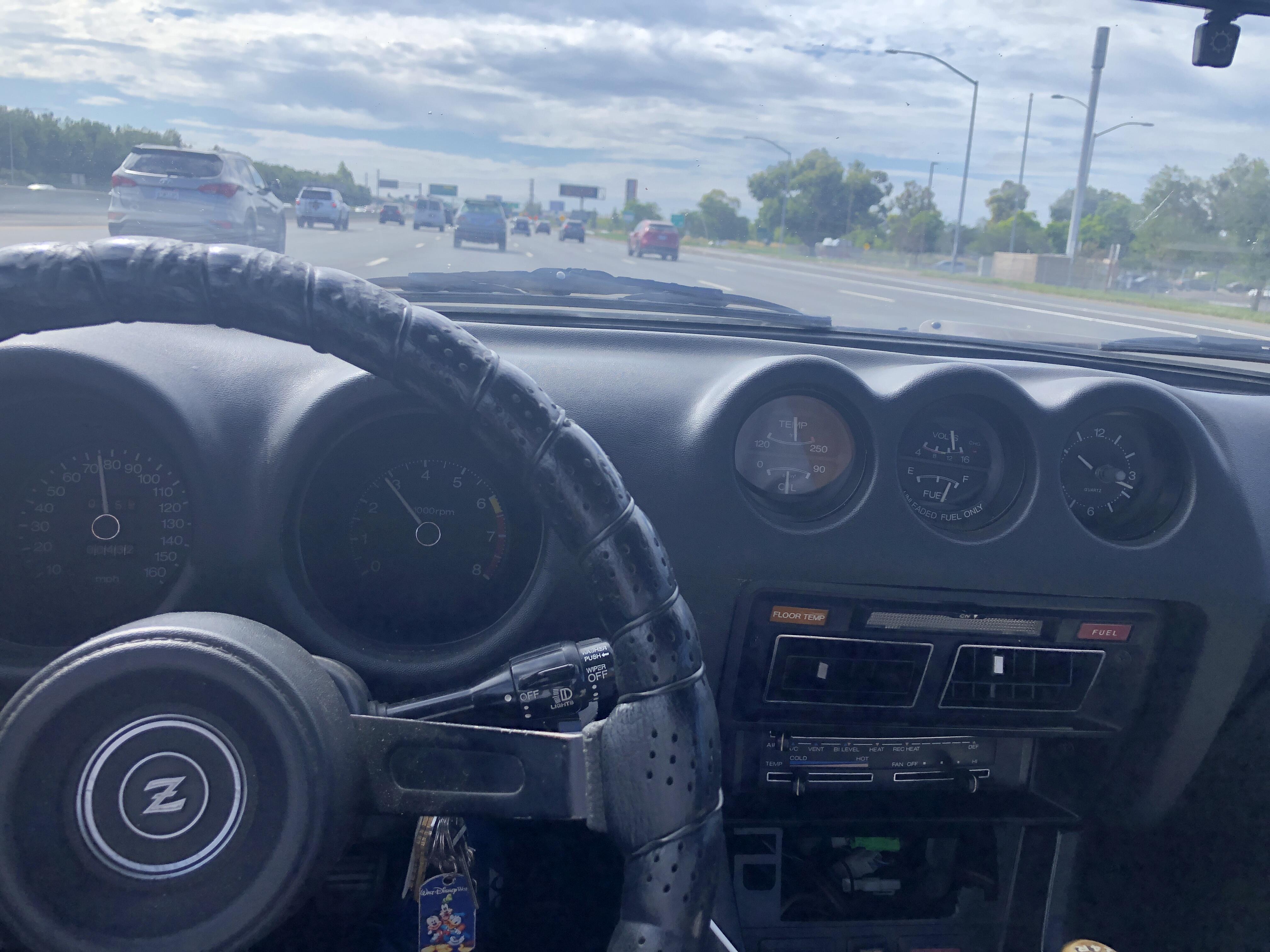
The voltage and especially the fuel gauge. I want the fuel gauge always to be on the right side 😉
-
I think I looked at this the wrong way. Before the radiator flushed, buildup, calcium… prevent the heat from dissipate proper. Hence, in turn not able to heat up the bimetal in the clutch fan that allowed it to engage as frequent as it is now. today is heat record at my area. Triple digits, 112 degrees at 10am time frame and I was driving for an hour on freeway. The temperature gauge’s needle just a hair pass the F letter. I think the engine is still within optimal operation. The clutch fan engaged constantly. AC was on the whole time and I experienced no lost of power. It looked a little bit hot but I think it is ok. Just annoyed the clutch fan is loud. Hope the other drivers with obnoxious straight pipe still able to hear their own engine’s backfired 🙂

-
very nice. Does the surface flat or has the contour like the original headlight? do you have a side image to show it?
-
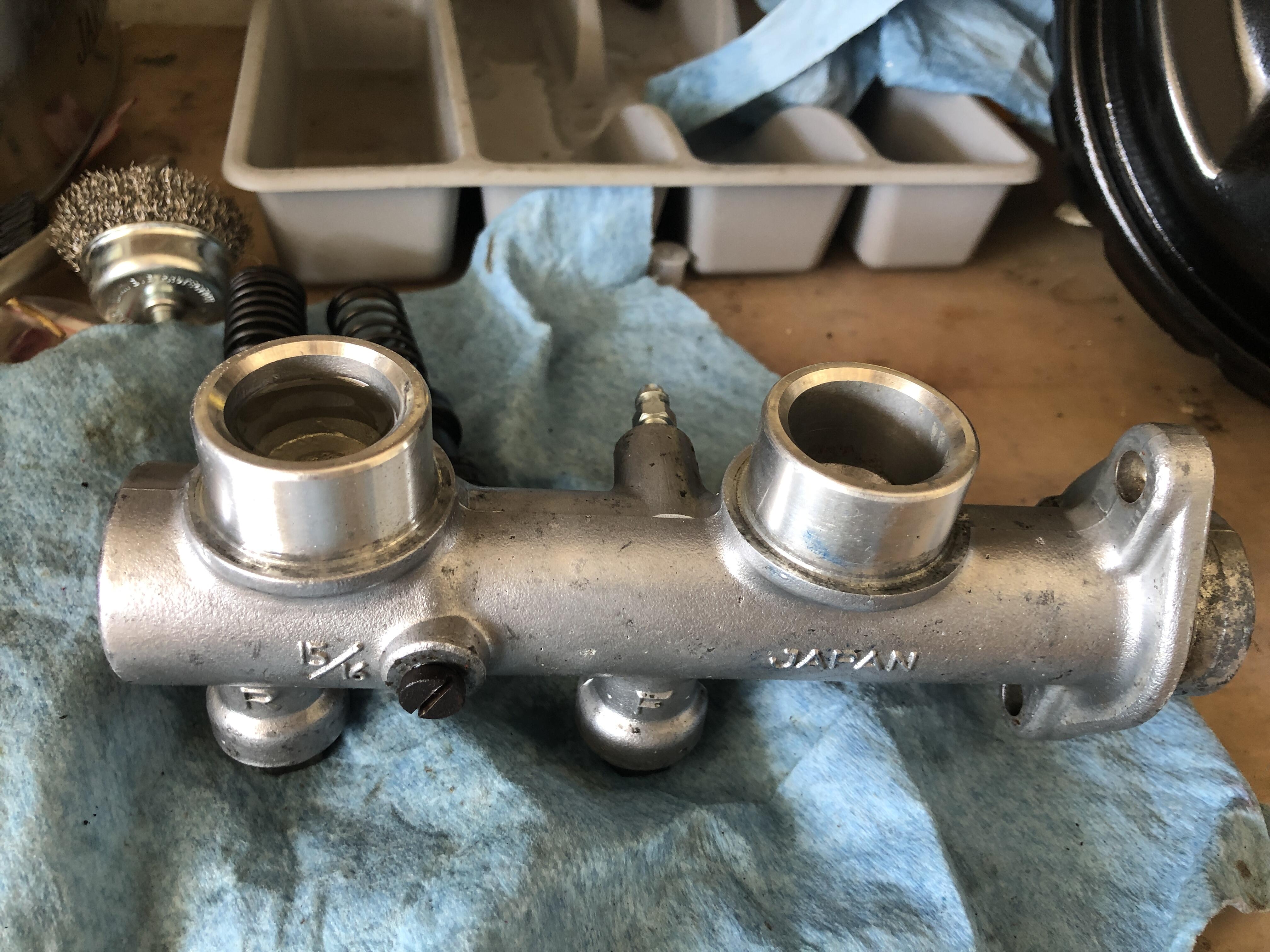
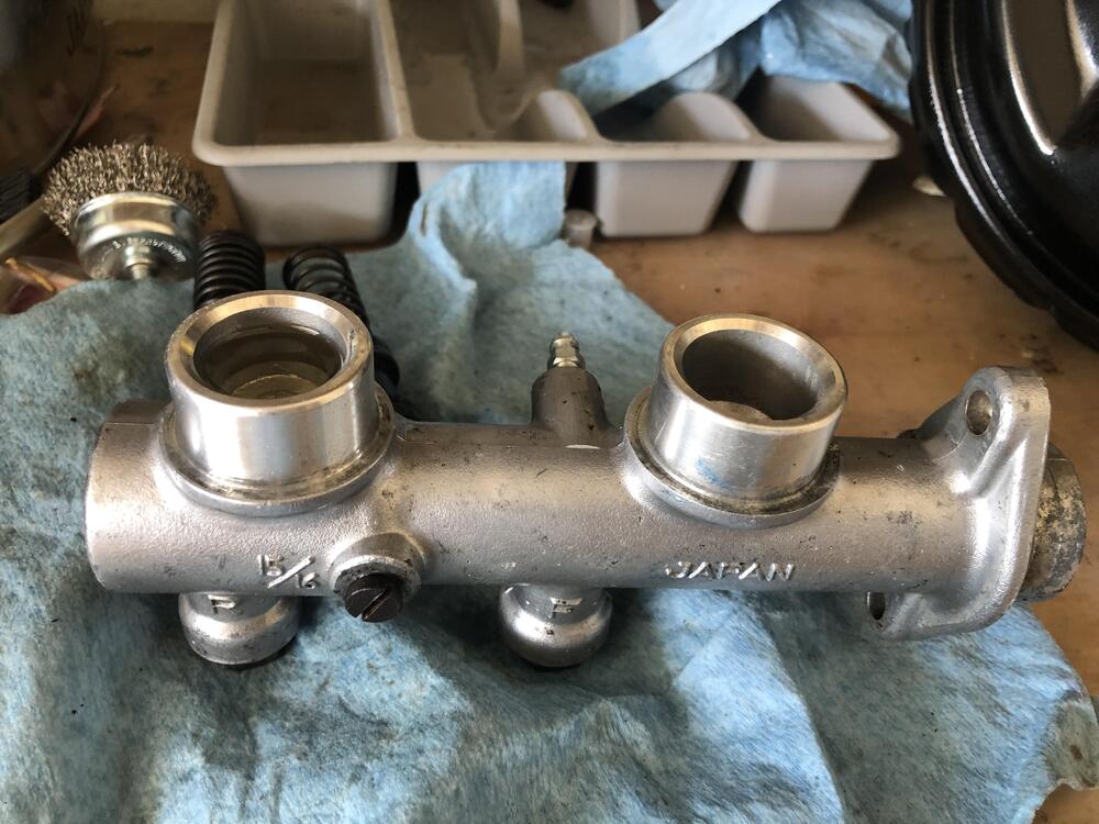
It is used. I bought the Tokico rebuild kit. Apparently, a close examine the Tokico and the Nabco, the Nabco is a bout 1mm shorter on both piston. I think the Tokico pistons block the holes. That's why no fluid gotten into the bore. ahh well, probably a remanufactured one probably a better route.
-
Alright folk i changed direction a bit about mechanical gauge…. I bought another oil pressure sender instead. This sender is a bit less resistance I think. 75ohms at 0 PSI. The fitting is NPT instead of BPST, hence another adapter. At cold start, oil gauge is very close to middle and when engine warms up, gauge points about middle. I guess due to the less resistance, that’s why the gauge display as such. But for sure having the gauge actually display something gives a bit a peace of mind. another successful day is I finally pay attention to the AC vacuum. I didn’t adjust it correct. At idle, when AC is engaged, there’s a vacuum at the throttle body to increase RPM a bit to keep the engine healthy. last couple of weeks, with you guys help, I’ve able to solve the flasher blown fuse, no heat at fuses box, voltage regulator look healthy. the next challenge is the fan clutch keep engaged too frequent.

-
Found the tire size and type http://zhome.com/BRETotal/Tires/BajaTires.htm
-
Folks! I’m in the process of evaluating whether to upgrade the 15/16” master cylinder with the 10” boost master from 280zx 1979. I tried to bench bleed the master cylinder and observed the below behavior. notice, I didn’t mount the reservoirs on yet. fill up the cups and it’s very slowly draw in the fluid into the bore and out the F and R outlets. I tried to tap on the side to see any bubble coming out. Very little. I even try to pump the cylinder and seem like just air coming out. Fill up the cups and left overnight, the F seem to be able to drain completely. do I need to mount the reservoirs to help with the gravity to pull in more fluid?

-
Does anyone know what type of tires these are? The size and whether it’s street friendly? They’re looking like they can sink a claw into the asphalt

-
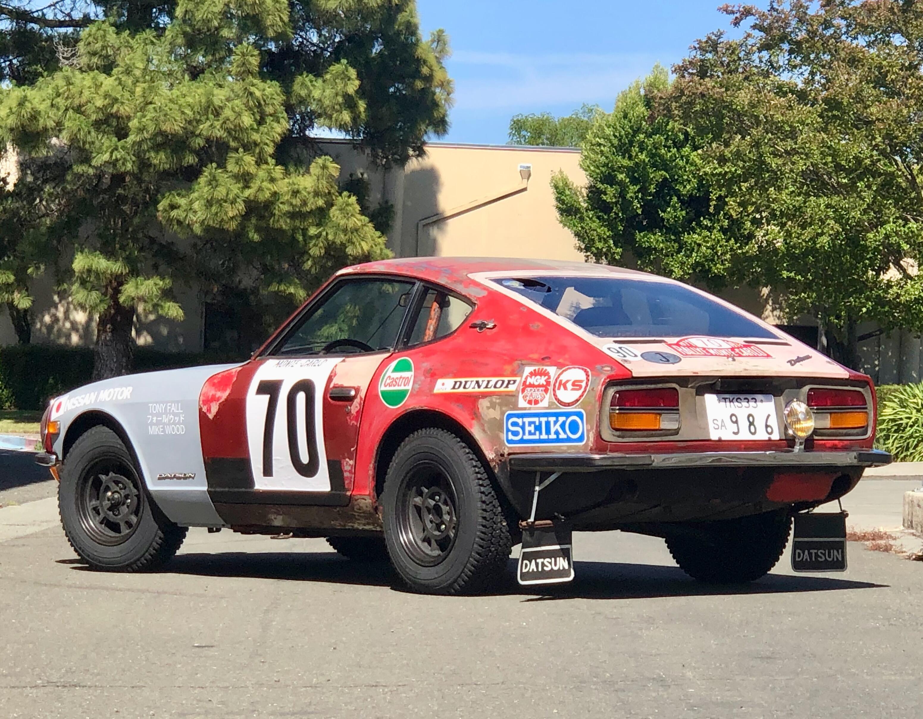
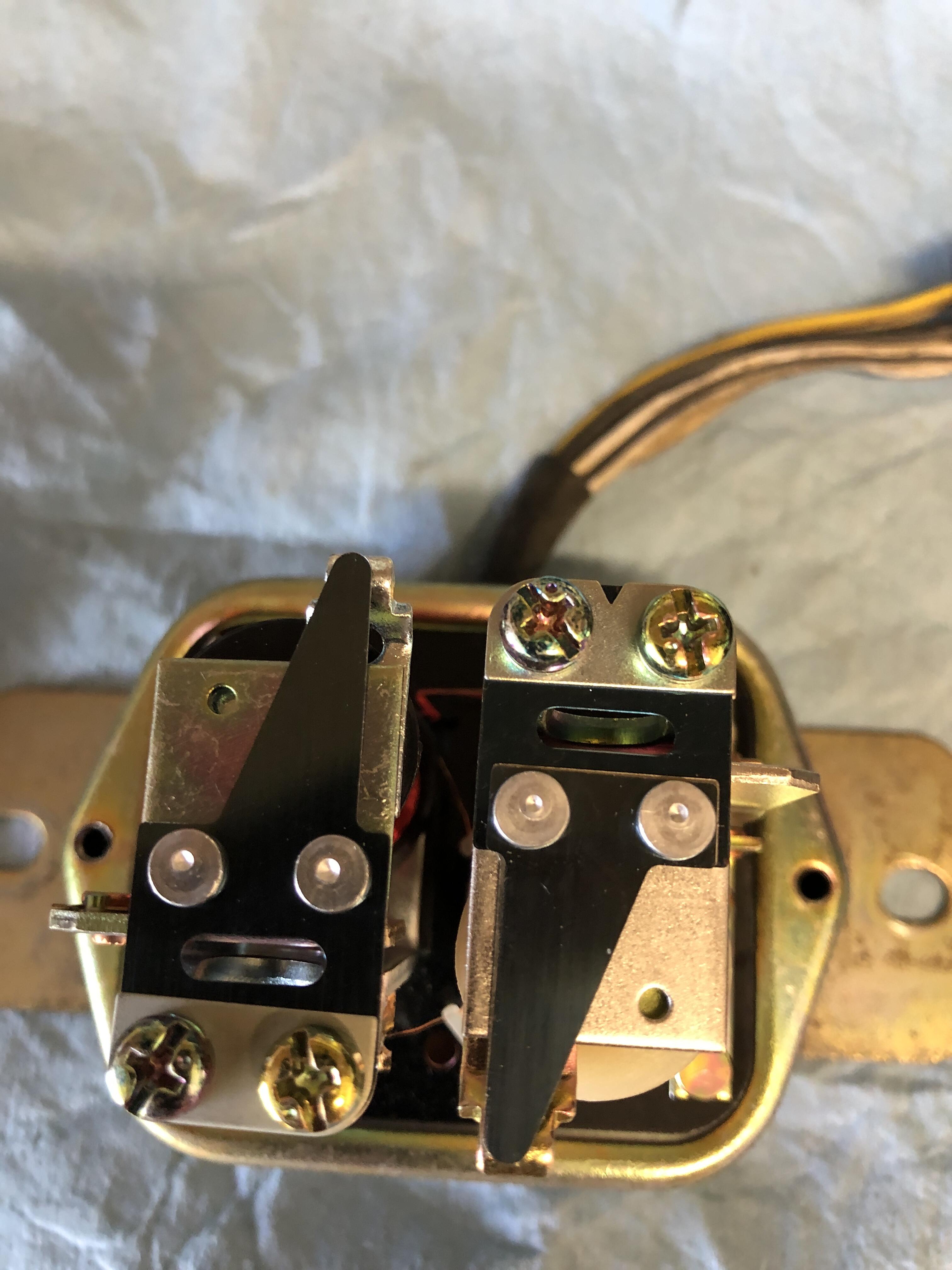
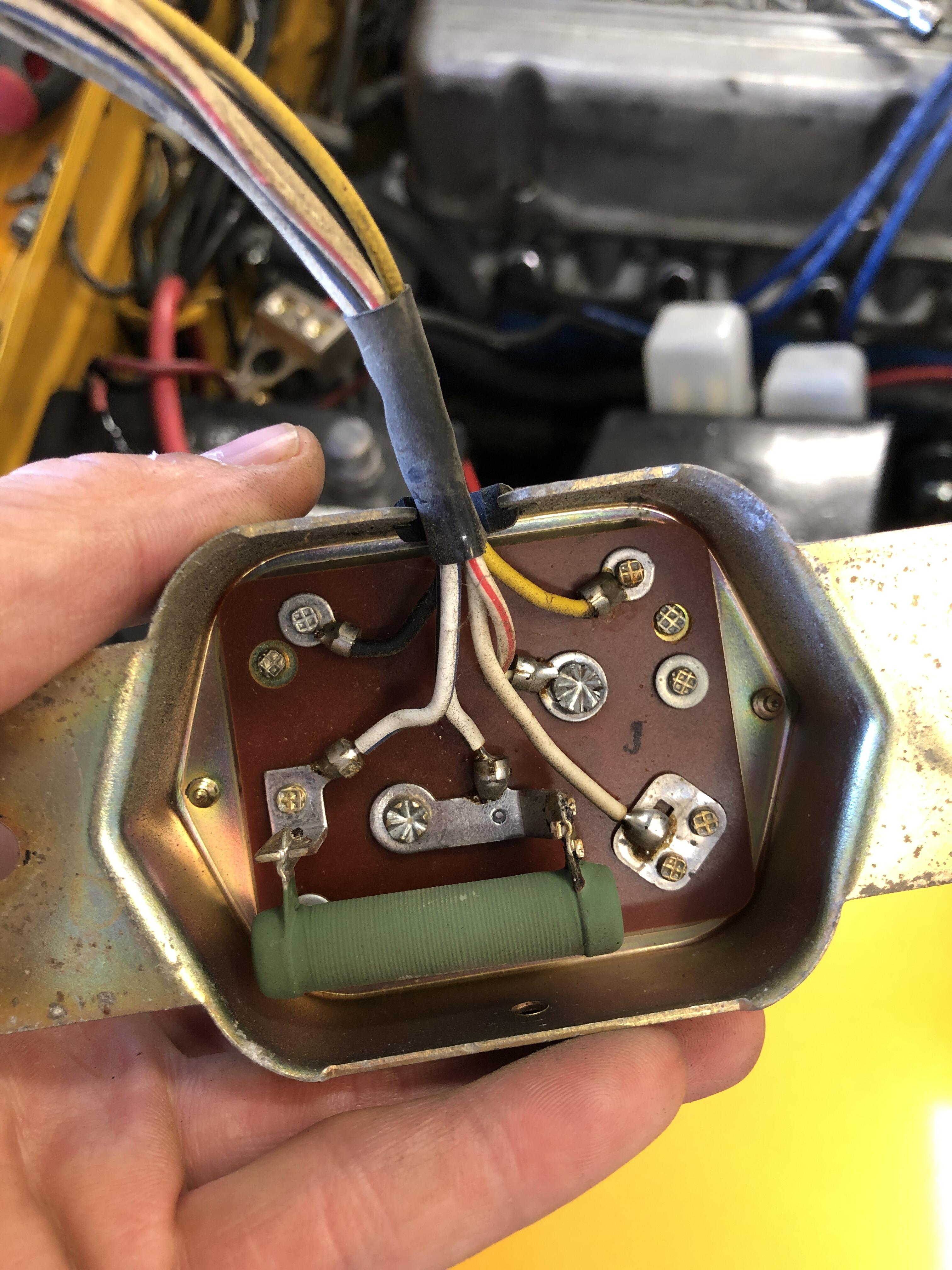
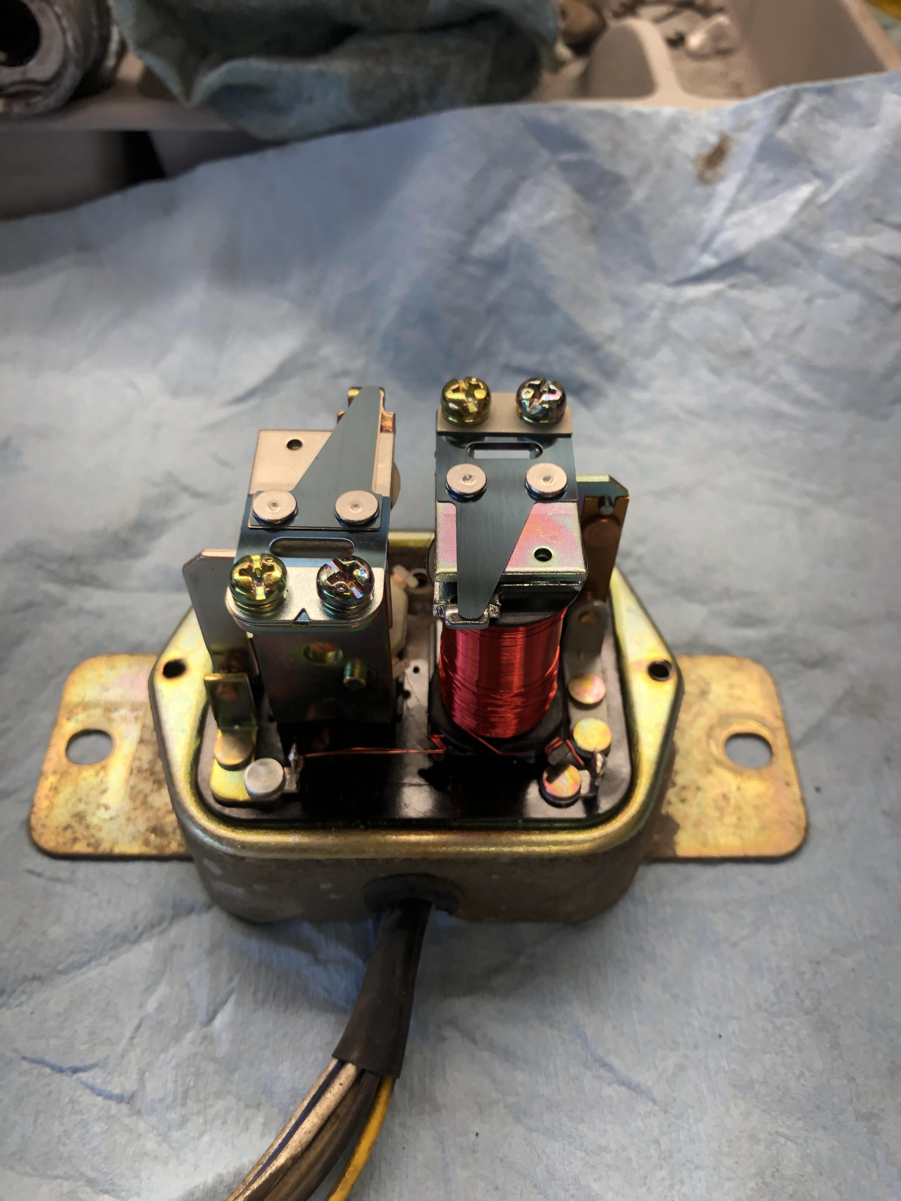
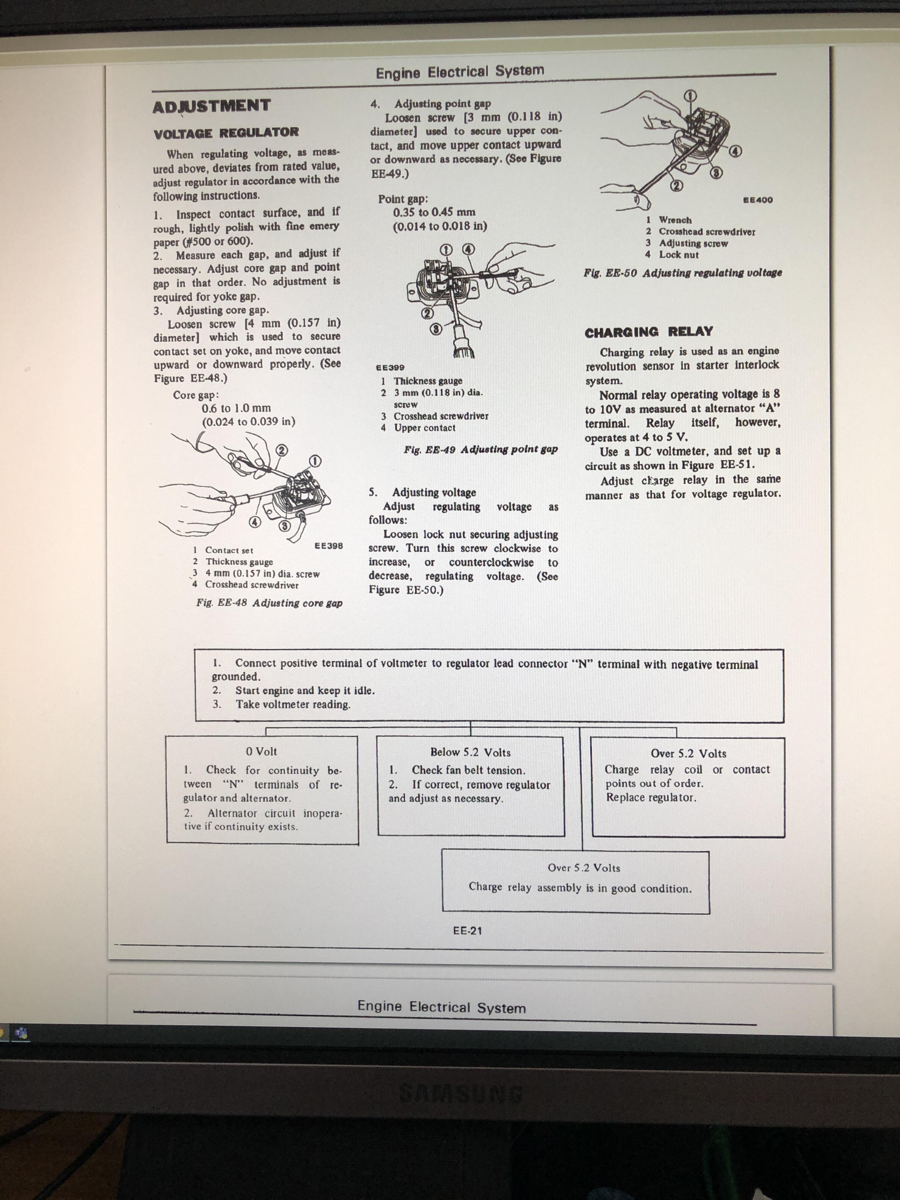
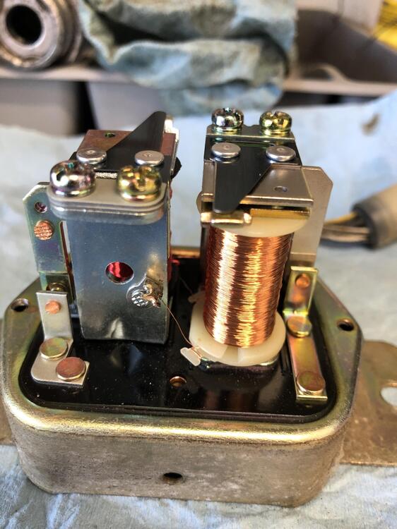
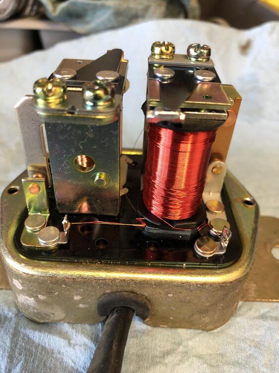
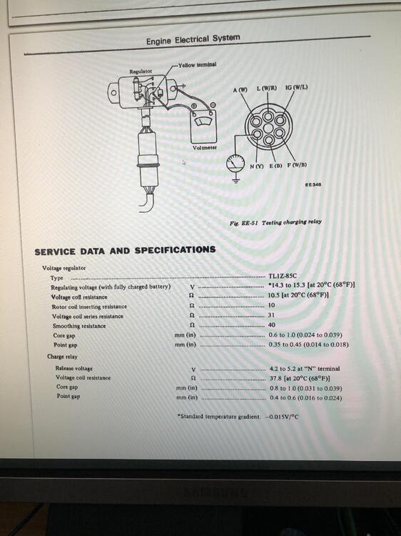
The service manual is the the original VR that has the screw to adjust the contact points, I think. The one in my car is replaced I believe. it’s harder to adjust this type than the one mentioned in the service manual. However, it is adjustable. The 2 screws holds T contact point. It is shape like a T. It can be moved back and forth . The top of the T, I call it a blade, act like a spring tension. Move closer to the screws strengthen the spring. I think the coils below the top of the T, magnetized when energized. It took me no less than 10 tried to get it under 14v. Seem like idling voltage and driving voltage have different behavior. One of the try I did, idling was 13v but while driving it was under 11v and sometime the charge light turn on/off while driving.
-
Not sure howto go about over 5.2v is bad/good base on the service manual… anyway, I adjusted the voltage regulator. At idle, the charge fluctuate at 5.6v. Also at idle without load nicely around 12.7v and at 3000RPM, hovering around 13.8v, if the cigarette voltmeter as suggested any accuracy. Still, better than +15v before. Thanks for noticing the high voltage and suggesting the cigarette. Smoking hot 🥵
-
Look like the voltage regulator has been replaced. I’m trying to follow the instructions to adjust the voltage regulator but seem like there isn’t any screw to adjust the gap of the contact point. Also, the instruction for adjusting the charge is conflicted. One box says if it’s over 5.2v, replace and the second box say everything is in working order. Perhaps they meant 15.2v? Missing number 1?


-
yes. It was disconnected from the sender unit. I'll measure the voltage fluctuate when I'm home from work.
-
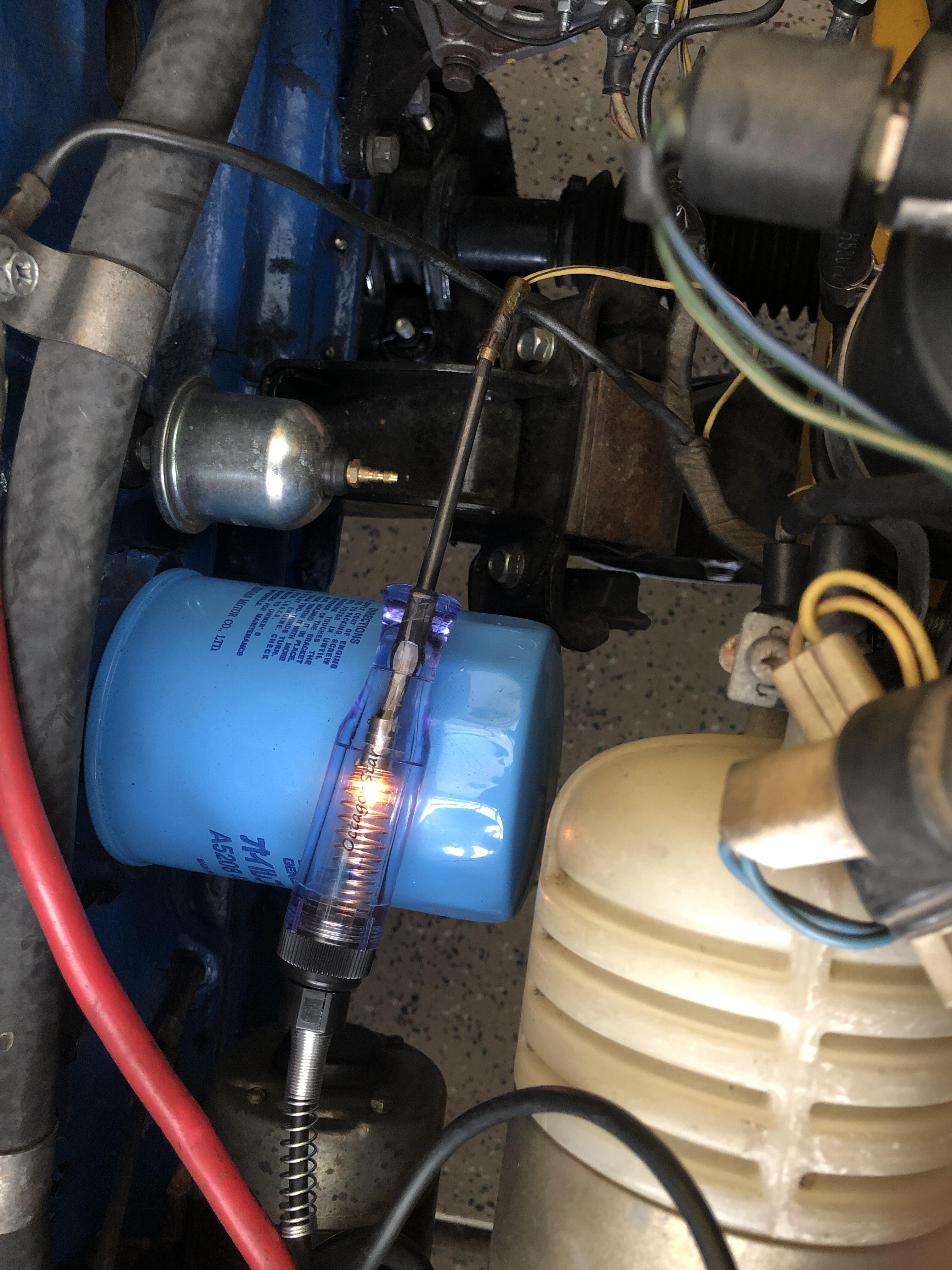
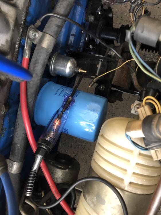
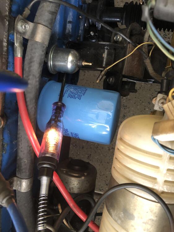
the oil sending unit resistance? I probably did it wrong ... What I did was to turn on the voltmeter to ohm, stick one lead to the sender's bullet point, and the other pin to ground. Using Light to test and notice the light strobing oil_pressure.mp4 Using voltmeter to measure the resistance. oil_pressure2.mp4
-
15.7 was from the new gadget you recommended. One down side is that the headlight switch block completely the cigarette lighter. I had to till my head right, down toward the center to take a peak 😉 Ahh well, it's an add-on, not by design I suppose. I will see when I have some free time, will open the voltage regulator and see if I can rebuild/clean up. For now, I'm turning on the headlights to keep the voltage down while on 3K RPM. This post is definitely weird ... going to the doctor for a splinter removal and now all the doctors/specialists found bunch of other ailments 😉 Got to love owning a "classic" car!!!!!
-
One of the goodies came. @Zed Head, @SteveJ, the voltage fluctuate up to 15.7v at 3000 RPM. this is without any other load such as AC, headlights…. I had to turn on headlight while cruising the freeway to bring it down to 13.6v or so. saw a clip on YouTube by @Dave WMopen up the regulator. Has anyone rebuild it? https://youtu.be/9qeYW_Rnoo4
-
Yes. I read that post. The gauge works. Ground the wire and within seconds the needle pegged to the right. definitely there’s resistant in the sender unit. The test light blinking but dim compare to the chassis. I did rev up the engine but test light behave the same. I wonder should the sender varies when engine is rev up?!. how do I measure resistance on the sender while engine is running? Just connect ohm meter to the sender pin and to chassis ?
-
Not sure how the oil sender unit should function… below are some photos at various points. The light is dimmed at the bullet pin. I also had a video showing the light is blinking constantly at the tip. Will attach the video later.

-
Found the condenser. How to check if it’s working?