Jeff Berk
Free Member
-
Joined
-
Last visited
Everything posted by Jeff Berk
-
 Thanks, I'm aware about the ring gear size issue because I had to machine mine on a lathe to get it to fit the LSD housing. I'm beginning to think the KAAZ LSD was designed for the Japanese market Z's.
 -
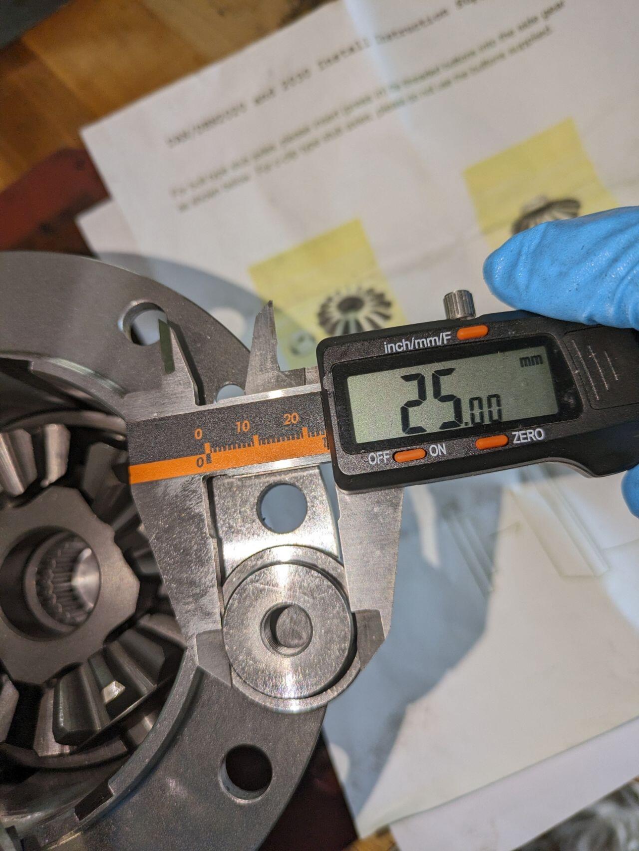
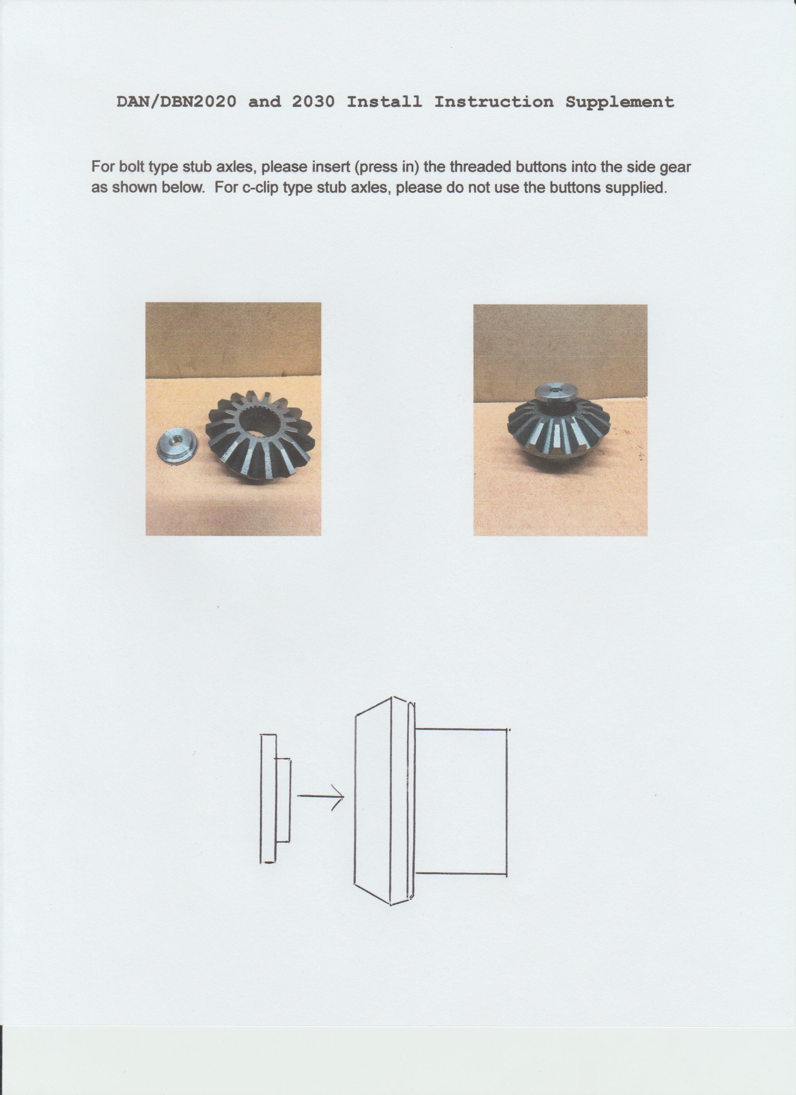
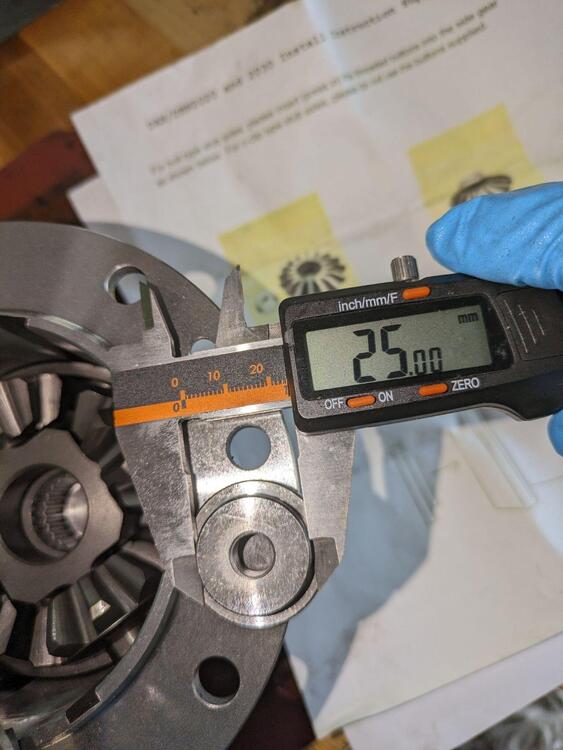
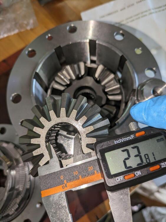
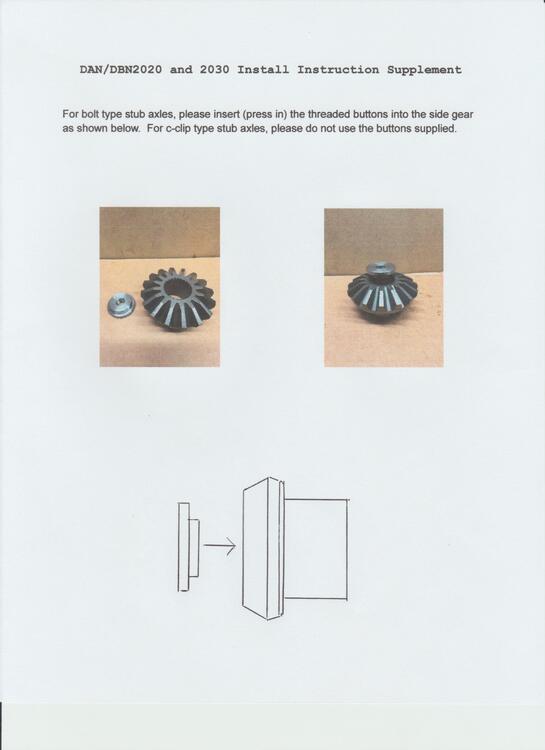
Well, I'm still trying to get the LSD installed. The technician at KAAZ told me that I could purchase different "end gears" that are designed for screw type stub axels. He was traveling to Japan and would have them delivered to his hotel and bring them back to the States to ship to me. It would cost me about $350 but I really needed to get the Lsd installed so I agreed. A few days after he shipped them to me he e-mailed me again to say he discovered there was a threaded insert I could purchase for the existing end gears that would permit the use of the stock stub axels and I should send back (at KAAZ's expense) the new end gears I purchased. It took two weeks to get the threaded inserts and I tried to install them today. They don't fit. I can machine them down to make them fit but by then, it might be just as easy to machine my own from scratch. Lets see what KAAZ suggests now.
-
I hope to see you around Cleveland sometime. My car is out of commission right now waiting on a part for the LSD I'm installing. Jeff
-
Just wondering, why did you go to SU's and not stay with the Mikuni carburetors?
-
At first I thought CO was joking, but after reading the zclub thread, I'm not too sure.
-
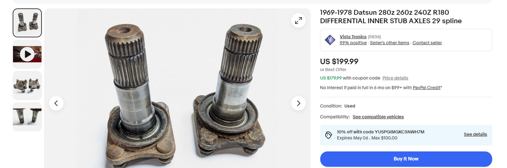
I just found this on e-bay but my car doesn't have this flange. The splined axle is part of the universal yoke.
-
I finally was able to regain access to my garage to install the differential and ran into a (major) glitch. My axle ends will not attach to the new differential. Everything went fine, other than a smashed finger, until I tried to screw in the yoke fixing bolt. It would just spin. It was then that I realized that there was nothing to screw it into. I contacted KAAZ in the US and was told that the unit I purchased DAN2020 is designed for a C-clip stub. They do have a unit designed for a bolt-type stub like used in the early Skylines DAN2030. Dose anyone know where I can get a stub designed for C-clip installation or a drawing showing the exact location and dimensions of the C-clip slot so I can machine one on my existing stubs? Note that although KAAZ tech support identified the DAN2020 as being the correct model for my car, I purchased it from a vendor in Japan in early December so that potentially complicates any exchange.
-
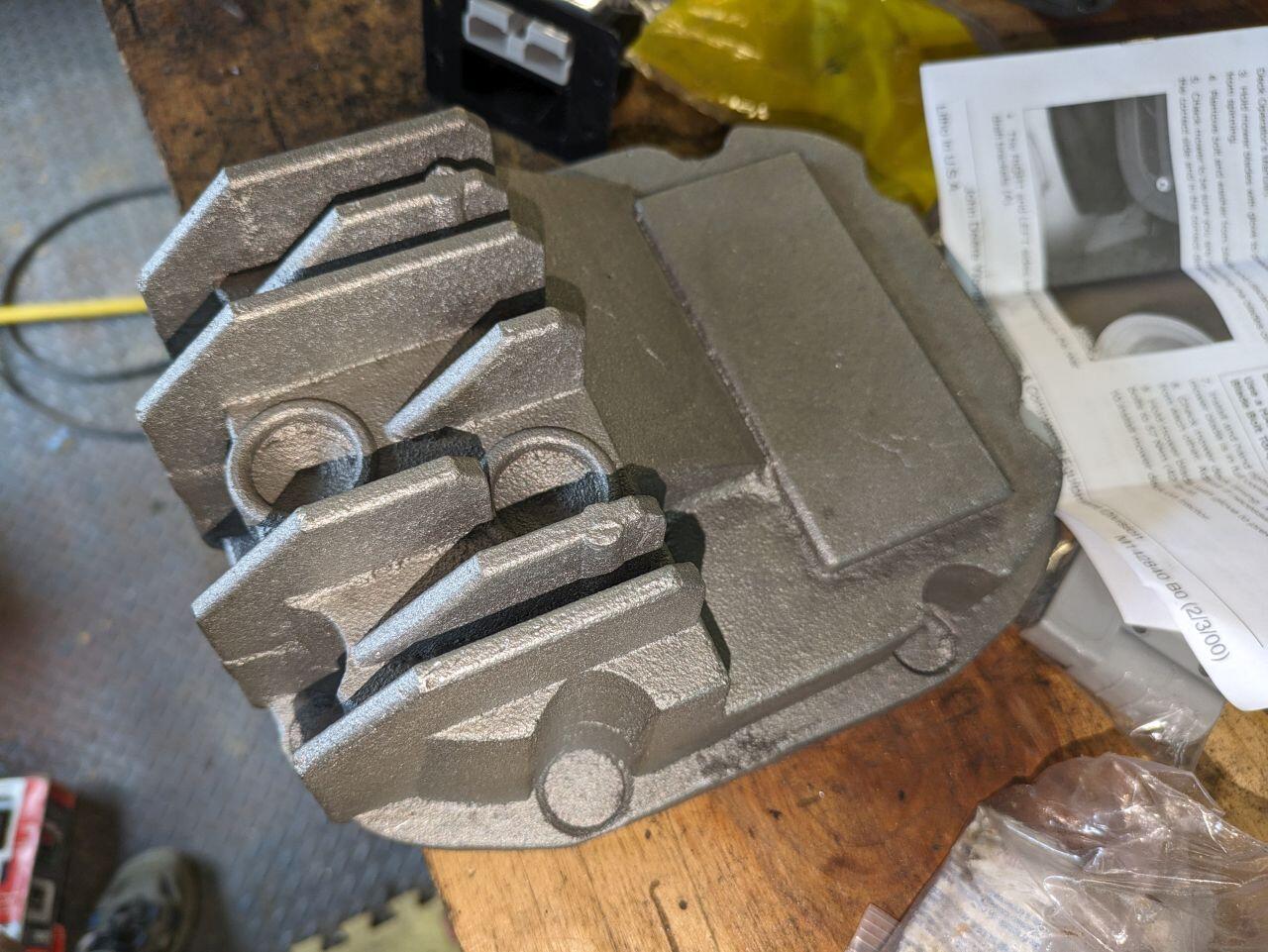
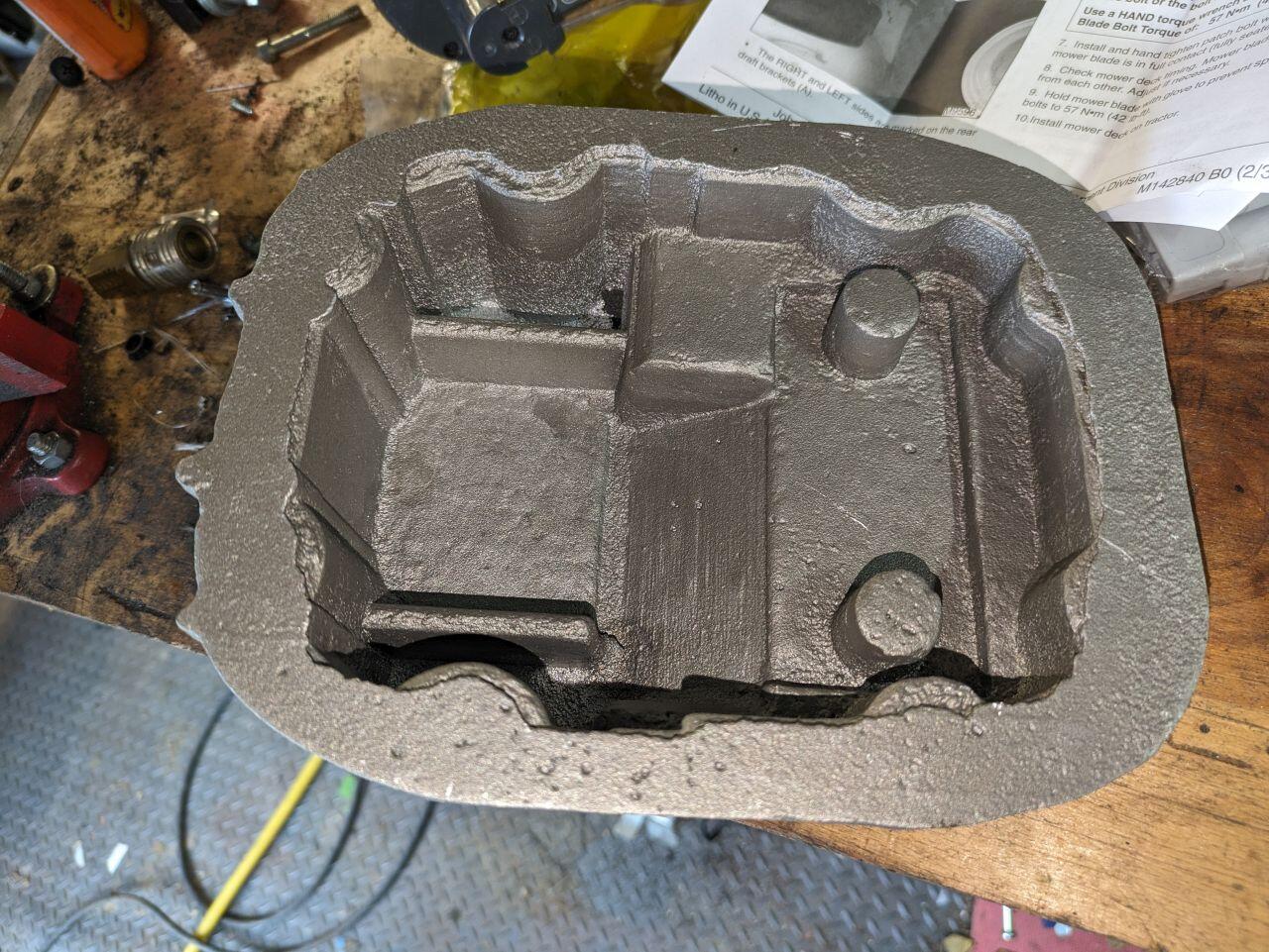
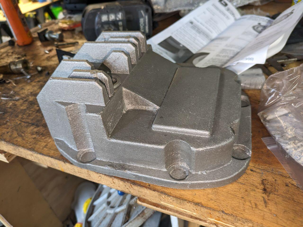
I was just installing the differential with the original cover when the post man pulled up with a package. It came to a little more than expected at around $60 plus $23 S&H, and will need a lot of post-casting cleanup but for a first custom made part, I'm more than satisfied.


-
This is related to a project on another thread. I'm having a custom diff cover cast and need to tap it to accept the OEM plugs.
-
I wonder if it's actually 1/2-inch BSPT? They are almost interchangeable. If it is 1/2-inch NPT I should have one locally available.
-
Does anyone know the threading size for the differential drain and fill plugs. I tried to measure them and came up with 27x2.0 but apparently this was incorrect. My "Thread Detective" doesn't go this high.
-
-
Great mod! Any chance you still have that CAD file? Its a shame to cut up the cross member just to get the two saddles. Great paint job! I've been tempted to get one of the inflatable paint booths for the back yard or create a booth in the garage like you did. For now, I'll stick with vinyl wrap.
-
Patcon, I've been going through the pages of the Lily build and have not spotted that part yet. Can you give me some direction on where that section of the build thread is? Jeff
-
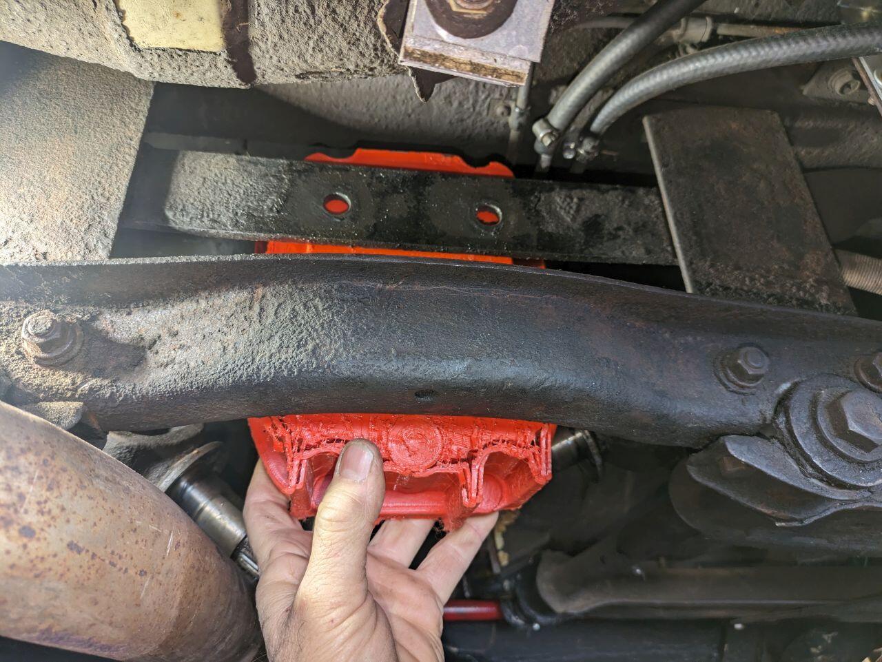
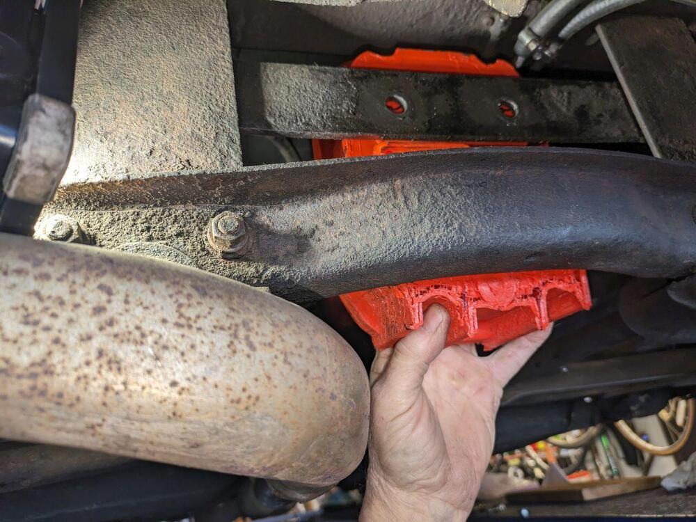
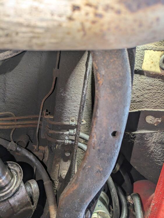
That cross member supports the transverse links which gives me pause. It might be possible to create a standoff to shift the cross member 2-3 inches to the rear. The question is: Does the improvement in heat dissipation from the LSD worth the change in design of the vehicle's suspension supports? It looks like this R200 finned cover had the same issue and required modification as well: https://protunerz.com/products/protunerz-billet-r200-finned-differential-cover My son's partially dissembled Lotus is back under the Z again making this more difficult.
-
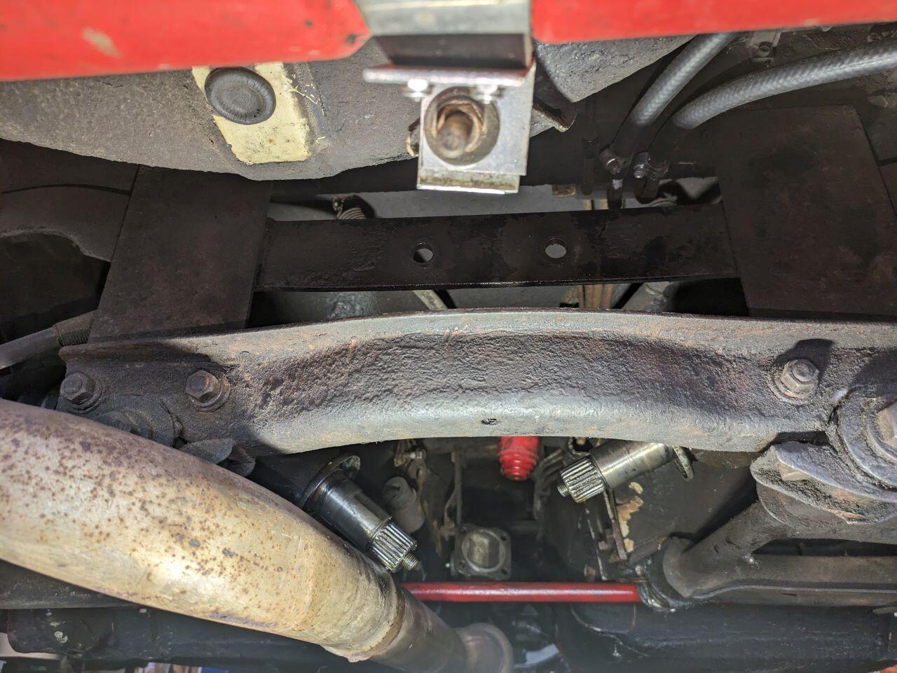
Back to the drawing board. I got my son to push his '05 Lotus out from under my Z which is up on a lift so I could check for fitment. When I tried to fit a prototype onto the mounting points I realized that there is a cross member below it that is in the way. I'm not sure what I can do other than greatly reduce the reservoir volume and size of the heat exchange fins.


-
I saw that video and I included mounting points on the fins to attach a removable 1/8-inch thick scoop. I drilled out the fill plug and treaded it for a temperature sensor so that I could experiment with it during autocross to evaluate the effect. Anyone know the threading on the fill and drain plugs? I'm going to need to order a tap. I also need to locate the fill plug I tapped and promptly misplaced. My shop is a tiny corner of my garage and I still manage to misplace things.
-
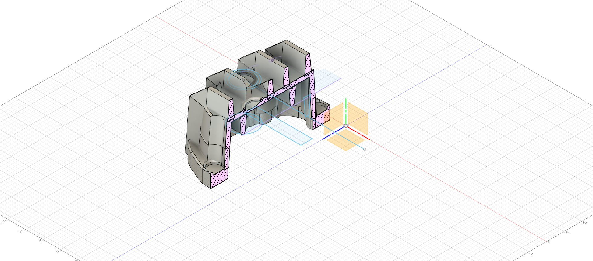
Right now it's looking at about eight pounds. I'm using the software to apply fillets where I can and I'll round the remaining edges post printing. The attached obj file is a viewable 3D file. It can be viewed using Paint 3D although it takes a couple of minutes to load. The stl file might work better depending on your software. differential with draft Rev 3 v5.obj differential with draft Rev 3 v5.stl
-
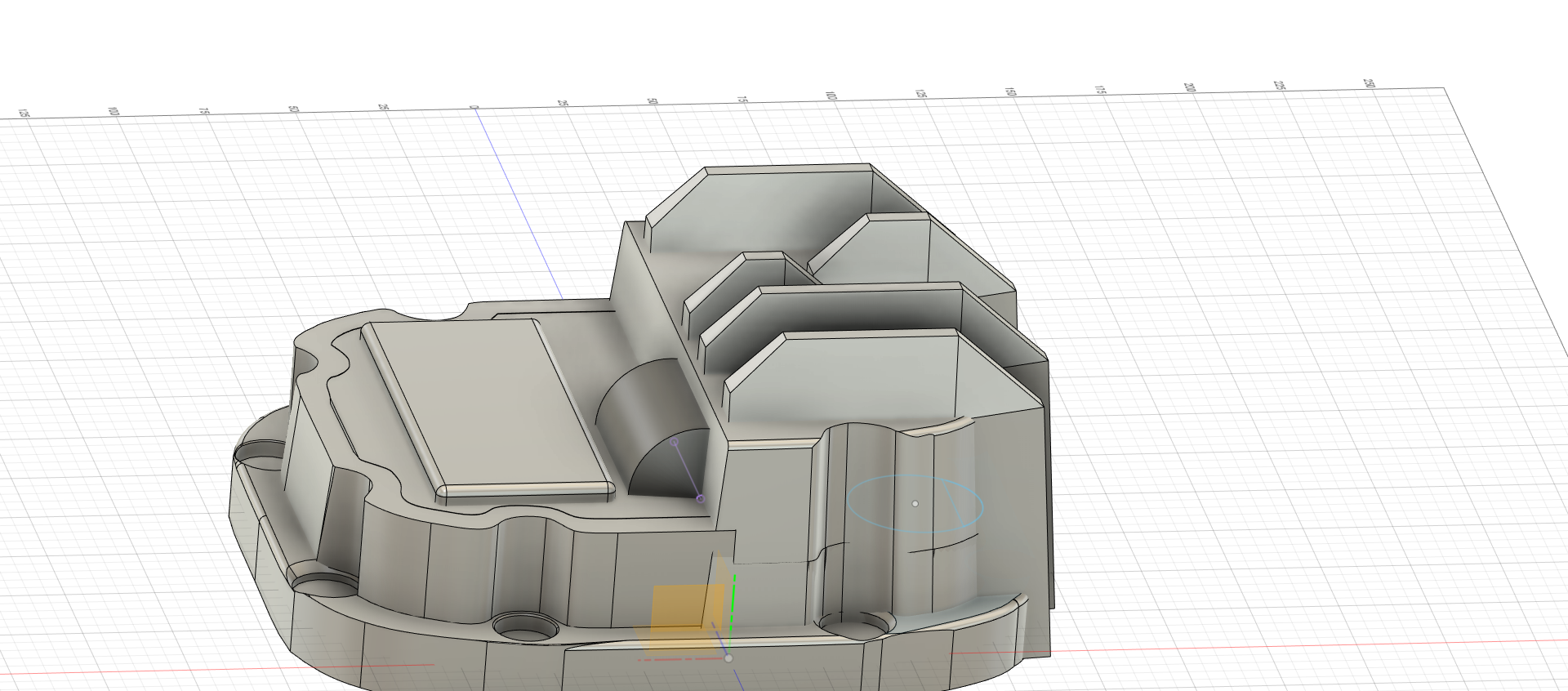
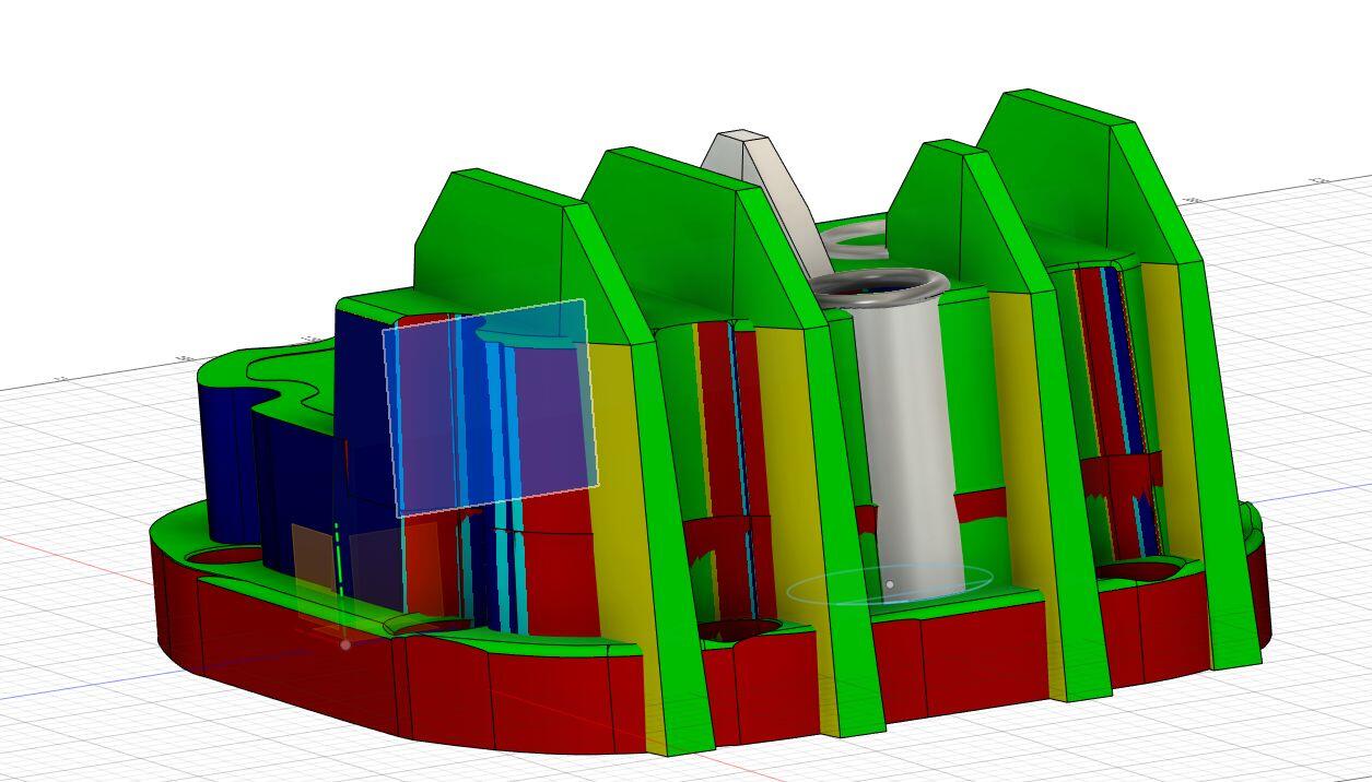
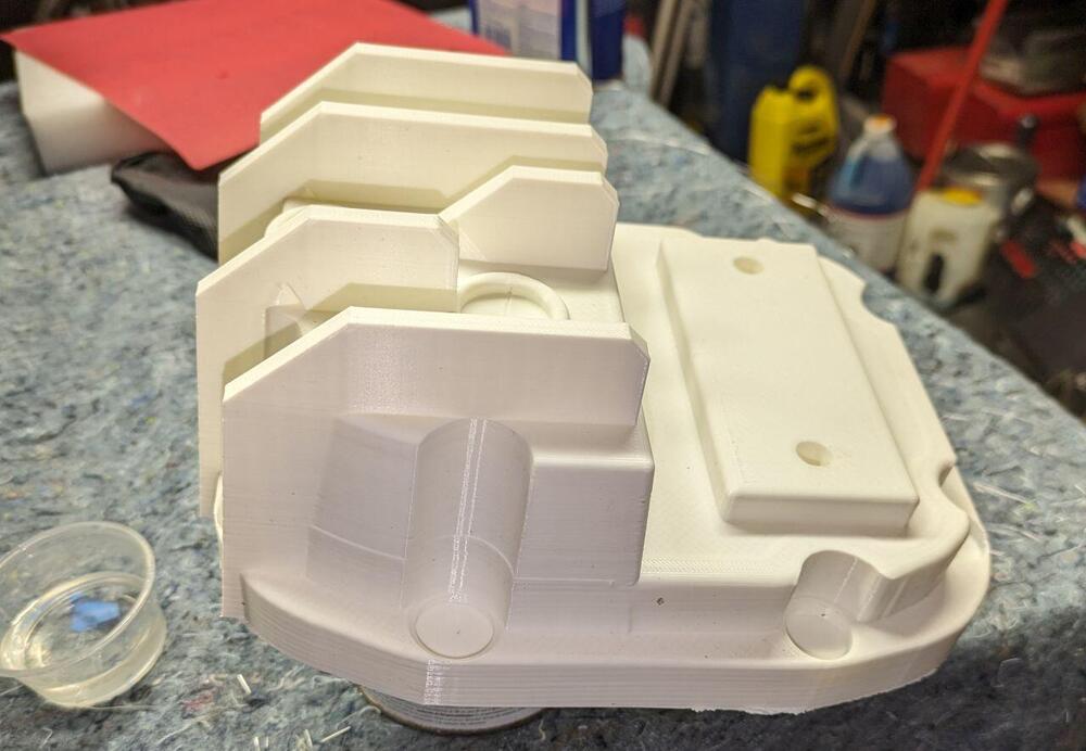
CO, Emmanuel didn't seem too concerned about the areas you marked so I'm assuming draft is not too important if the depth of that portion of the mold is not too great. I'm also not too competent in using Fusion 360 so adding draft in some areas could take me hours, if not days to figure out. In some cases, I've had to scrap the model and start from scratch. I'm currently struggling with modeling a channel to promote fluid circulation from the spinning ring gear. What is shown in this version is actually a model of the cavity. The solid portion of the channel will be covering it and then I'll change the channel part to a "cut". I'm sure the shell command would work better but I'm not too proficient in its application. Time is running out because Emmanuel only does aluminum castings every 3 to 4 months. If anyone has a suggestion, please speak up. Jeff

-
CO, Thanks for showing that. I think I have it fixed now. I used the drift feature in 360 Fusion to the angles until they changed from red. I'm considering adding a channel to aid in the flow of fluid that's splashed up by the ring gear. Grannyknot, You mean a group buy so we can get this part even cheaper? Lets wait until at least we see if this part works. Also, keep in mind that (1) a lot of post-cast work is necessary, and (2) I don't know what I'm doing. Jeff

-
I just got a call from Emmanuel at Cattail Forge and his only suggestions based on the 3D print I sent him were to add draft to the cooling fins along the bottom and to create the holes for the mounting studs using a template post casting. He also said that I should assume 1.3% shrinkage (there's that image again). I confirmed with him that labor would be about $35 and the aluminum was $3 per pound. His next aluminum forging will be in about 4 weeks.
-
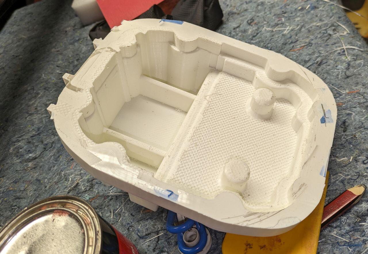
I originally tried to use a 3D scan but that got to difficult using the available software so I started from scratch. This is likely my 3rd iteration of the part. The problem with the version in Post #16 was the expanded reservoir did not have enough draft and the only way to add it was to redo much of the reservoir. The internal bracing was mostly eliminated because I felt the one I was modeling seemed to be thick enough. The internal fins were intended to provide better heat transfer and also some internal support. I was considering adding some internal channeling in the next iteration along with suggestions offered by the forger.
-
CO, Thanks for the review. I agree about the mustache mounting holes. The fill hole is offset from the internal fin. The Inspect>Section Analysis feature in Fusion 360 was handy for positioning these features. Unfortunately, I didn't spot the Inspect>Draft Analysis option in Fusion until after I printed the part. I noted a few faces that looked troubling in the analysis in my letter that accompanied the part to the forger. There's a steep learning curve with Fusion especially if you are not a CAD person. Unfortunately, it looks like you and the forge are about 6 1/2 hours away. Jeff

-
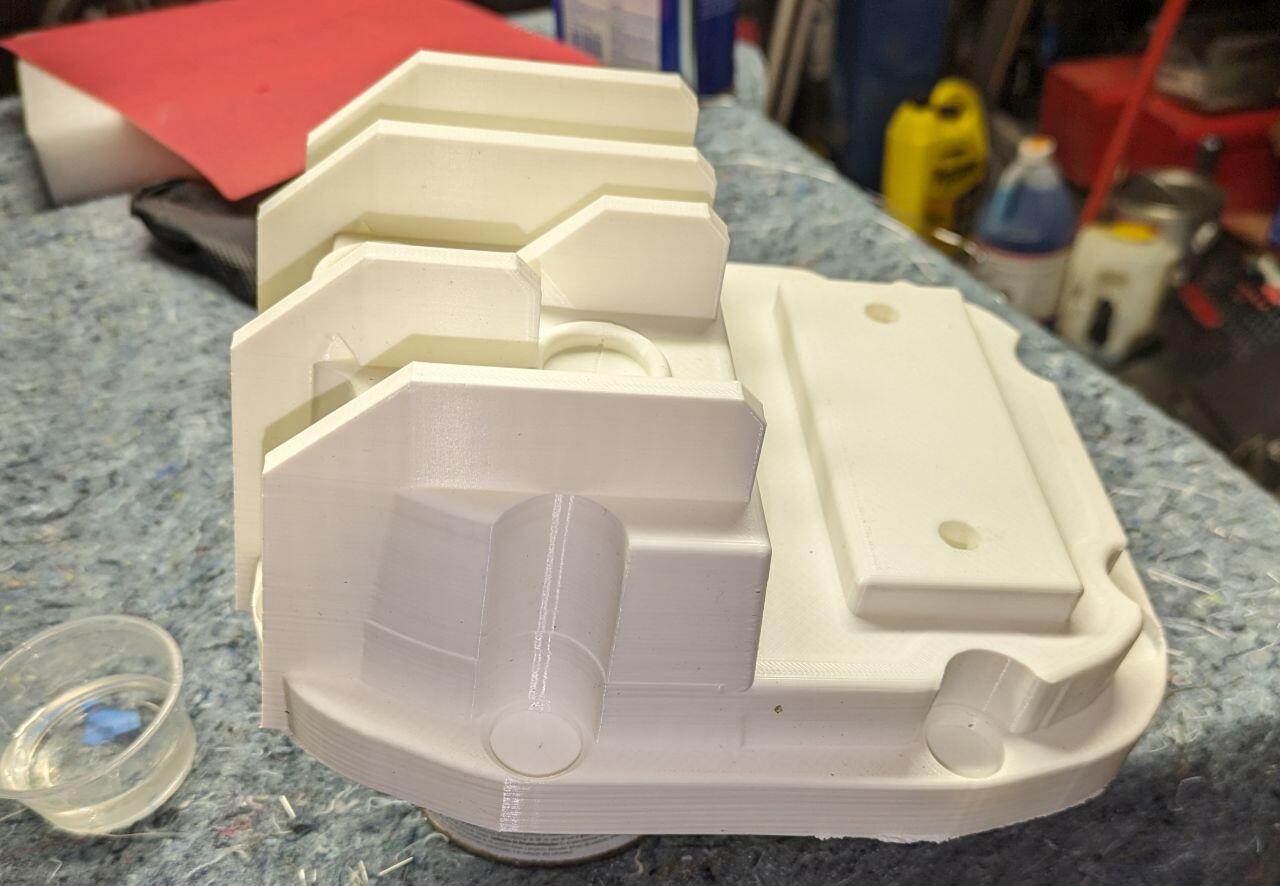
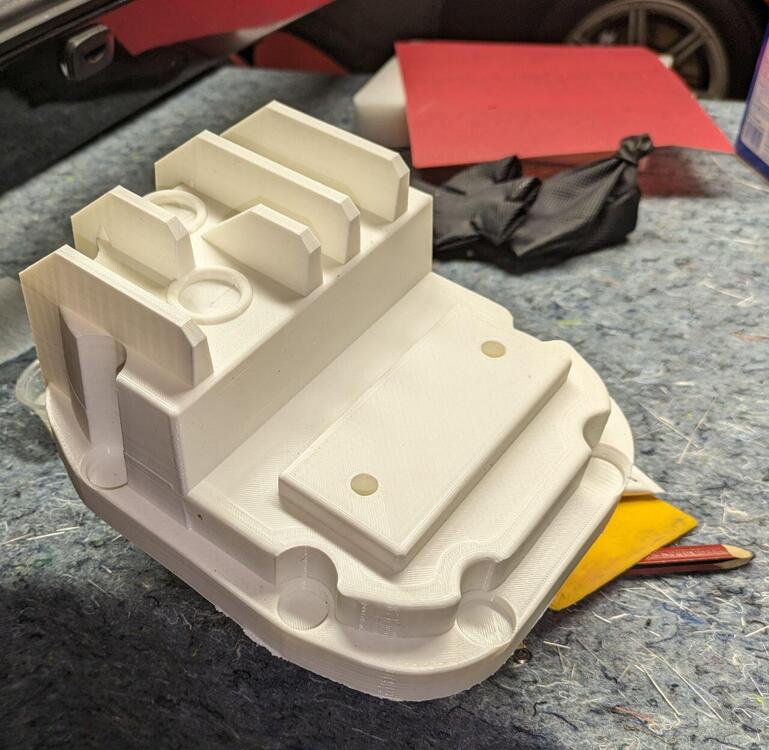
I just got the prototype printed. It took ~45 hours and 450 grams of PLA plastic. I test fitted the cover on my diff and there was a clearance issue that I'll need to address in the next iteration. I'm sending it off today to the guy in PA with a forge for him to offer suggestions. That brings up the question, is an operator of a forge called a forger?

-
I don't fully understand the process but I'm sending the caster a 3D printed part for them to create the mold. Its tempting to visit the caster's forge but its a 5-hour drive.