
Jeff Berk
Community Member
-
Joined
-
Last visited
Everything posted by Jeff Berk
-
I went to install the stainless steel trim around the window first but I need some reminding. The rubber seal has two distinct molded corners. Do the corners go at the top or bottom of the hatch?
-
I was looking into doing this as well but does bundling plug wires result in cross-talk between wires.
-
I just received my gasket for my 260z from Z-Car Depot today. Its marked as being from General Parts in Thailand. I'm maybe a week away from installing it and will post how well it fits.
-
Is there any reason why the door card could be either thicker or warped? I had to extend my splined regulator shaft because I replaced the vinyl with leather making it slightly thicker.
-
Has any of you seen examples of an entire Z body from China being transplanted onto a rusted out Z?
-
I watched this video and was going to post it here and Zed Head beat me to it. The catalog ZH posted only shows a small number of the parts and unfortunately don't list as fitting the 260z's. I like the fact that the narrator apparently owns a 240z so he focused in on them being made.
-
Maybe you can wait out the zstore. https://www.thezstore.com/product/195/aluminum-rear-brake-drum-70-78-240z-260z-280z
-
To answer your question about mixing parts between 4 and 5-speed transmissions, the parts with the same part numbers are interchangeable. That said, mixing used parts from different transmissions is less than ideal. Parts will wear in differently and can result in more backlash and noise. I rebuilt a 5 using some parts from a 4 and it worked fine but I couldn't tolerate the noise in all but 4th gear. I ended up having a local mechanic who specializes in old Zs rebuild one of my 5-speed transmissions. What part of the country are you located in?
-
DrFeelGood, Love that video! Jeff
-
I might be using the wrong terminology here so bear with me here. I didn't see the right seat belt reinforcement suggested by Patcon, on my Z. Is this part to be used if part 5 in the CarPartsManual.com is damaged? If so, I think that anchor point for the seat belt looks fine so unless I'm missing something, I'm assuming I don't need it. Please correct me if I'm wrong. I was going to order the inner dogleg but I'm confused as to what purpose it serves. It will be a bit of a pain to remove because it has a wire threaded through the large hole and it appears to be spot welded in several locations. Does it add support? KFvintage shows a part (pictured) that I'm assuming was mostly destroyed by rust: https://kfvintagejdm.com/shop/datsun/datsun-240z-rear-rigth-side-outer-rocker-repair-section/ Does this part go inside the rocker panel? A few responses up where I provided an image from a Nov. 2018 posting, there's what looks like this part but it has a hole in it that I'm assuming aligns with the seat belt bolt. I'm assuming that I need this part to reinforce the outer rocker panel.

-
I found this photo in a Nov. 2018 post. Other than the outer dog leg portion that I plan on buying, where can I get the other parts shown in the photo or do I need to fabricate them?

-
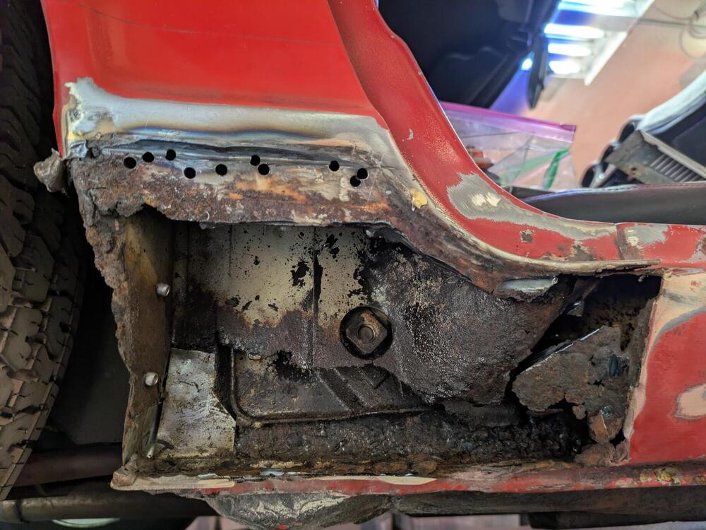
By middle reinforcing plate do you mean part 5 on this diagram I think its find. I've cleared away some of the heavily corroded metal and took another photo for a better look at the damage. There is a recent patch and blind rivets on the back and side wall I did 3 years ago to fix a hole that developed. I sprayed some rust sealing paint at that time. The sheet metal directly in front of part 5 is gone below the large nut but I'm not sure of its function and I cannot locate it on the CarPartsManual.com site.

-
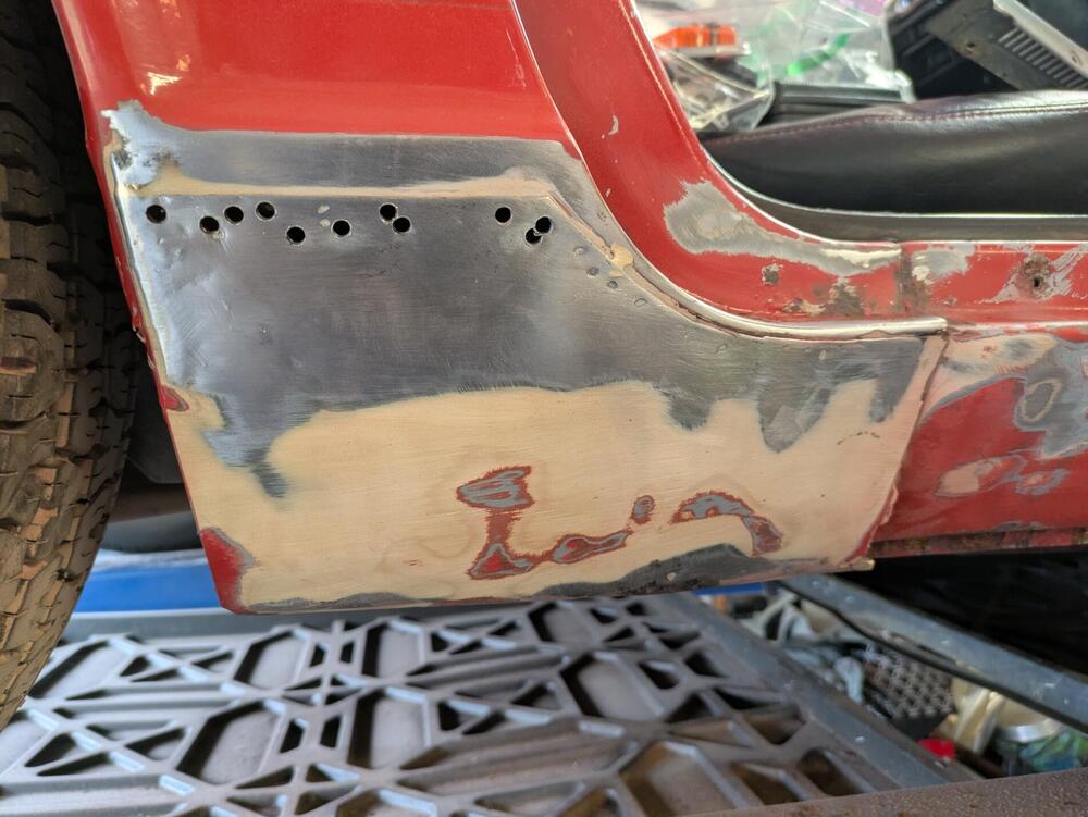
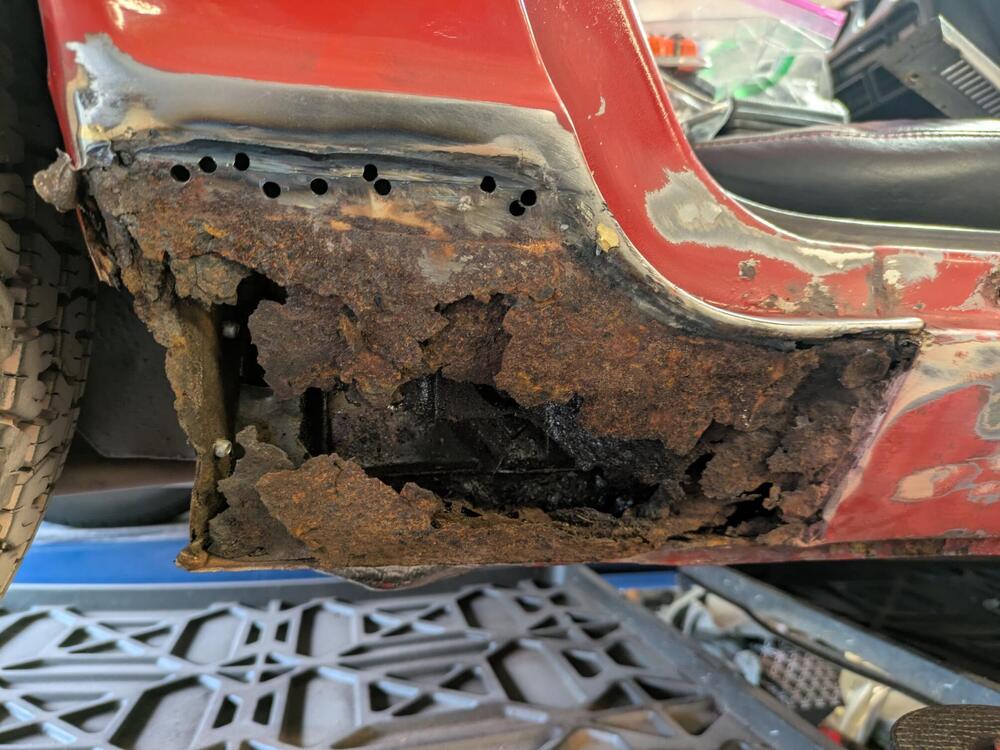
I'm preparing to repaint my '74 260z had have a few rust issues to attend to. A few months back I went to Pete's Custom Coachbuilding near Chagrin Falls, OH for their Octoberfest. They specialize in full restoration of Porsches. I asked them why they always grind off all the old paint when they restore a car and was told "you never know what you'll find under the paint." Well here's proof. I have what I thought was a complete repair record for my car that had no mention of rust repair or painting except for back in 1982. The bottom of the right dog leg came loose from the pinch weld and when I moved the bottom around, all this rust poured out. I started grinding off the old paint and found body filler. Then I found the patch. I cut out the old patch and found a rusted cavity. I'm picking up a new dog leg from a local supplier but I could use some input on if I need to address the rusted mess behind the new patch other than to cut out and paint with rust inhibitor. (note the drilled holes are me trying to drill out spot welds) Is there anything that needs reconstruction?
-
I have a '74 that I reinstalled a '74 radio in and I recall a bracket as shown in the FSM for this car. I don't see this on you image but I don't see how the radio could be properly supported without it. I usually remove the center console but I'm usually doing more than just pulling the radio. I'm not sure you can pull the radio without unbolting it from the bracket, at least on the 74's.

-
I would of thought the dye would of shown up at the point of leakage? I admit that I've only used dye on hydraulic systems to pinpoint leaks.
-
Did the oil include a UV dye?
-
I posted a recent issue with my Mallory ignition. The Uni-lite ignition module would test bad when the car would stop working but after it sat for awhile it would test fine and the car would run again. After changing the ignition module a couple of times, and with some input from this forum, it turns out that a PO installed a second shunt resistor in series with the first one. I removed the second resistor and so far the car has been working. I think the issue with the shunt was that on removing it, I observed the exposed coil of wire in the shunt was damaged and likely was not giving a constant resistance, possibly no continuity at times. Even if you have just the single shunt resistor, if it fails like this one did, it might cause the same issue.
-
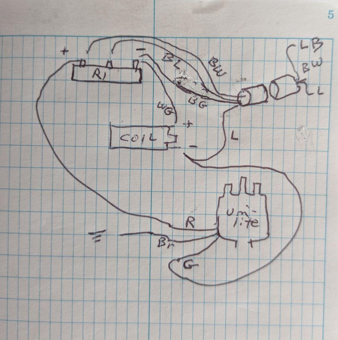
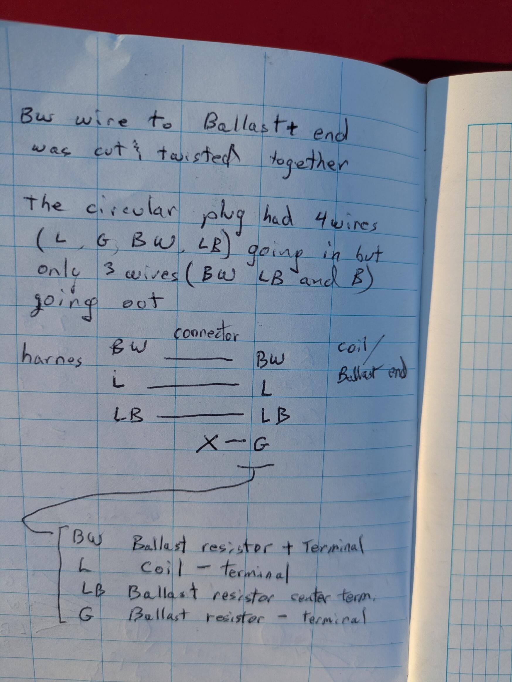
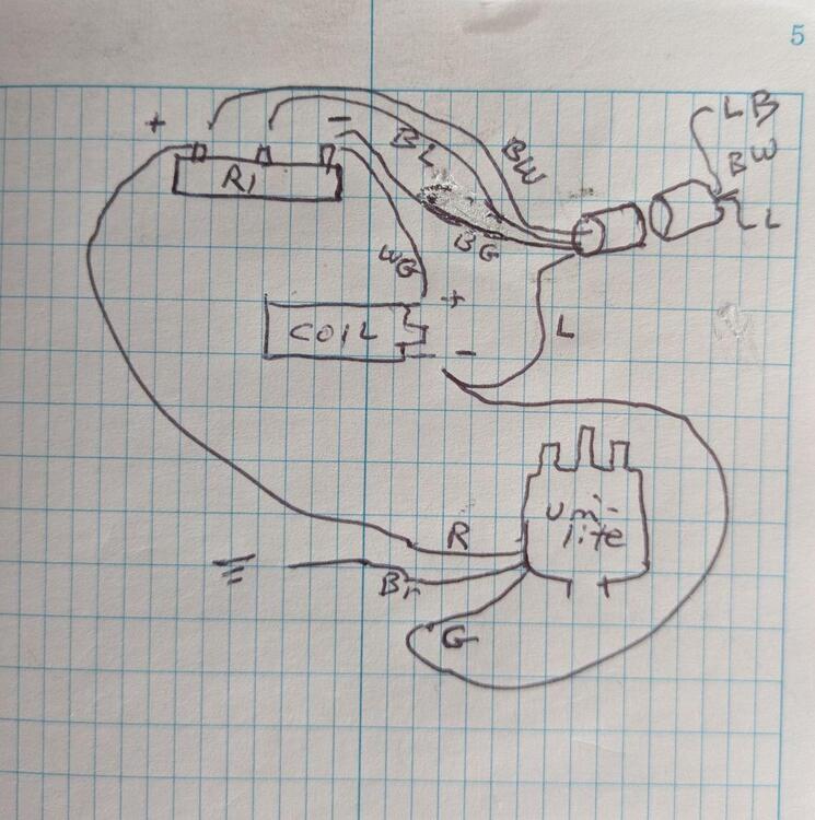
Sorry for the delay in getting back to this. I'm working out of town and only have weekends to visit my car. I think the problem may of been resolved or at least I can drive the car for more than 1/2 hour without the ignition failing. It must of been that extra ballast resistor or a high resistance from the taped splice. The car has been working for 7-8 years and only periodically had ignition issues so I'm assuming one or more weak links in the ignition began to fail. Here's the wiring as it stands now. Some of the colors were hard to see until I cleaned the wires off with solvent.
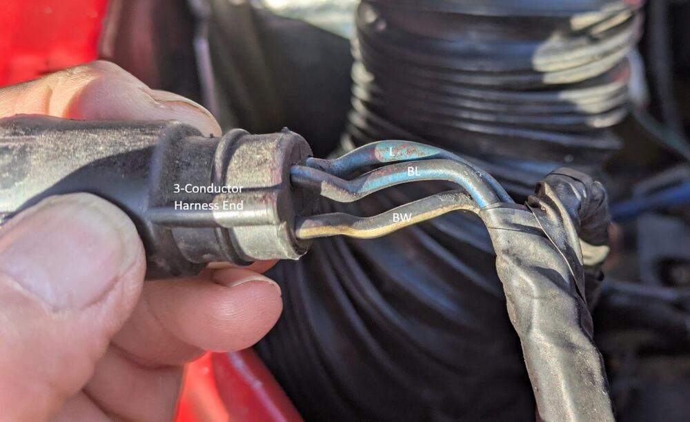
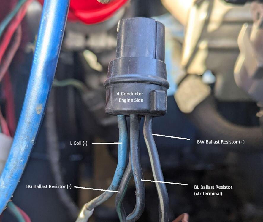
-
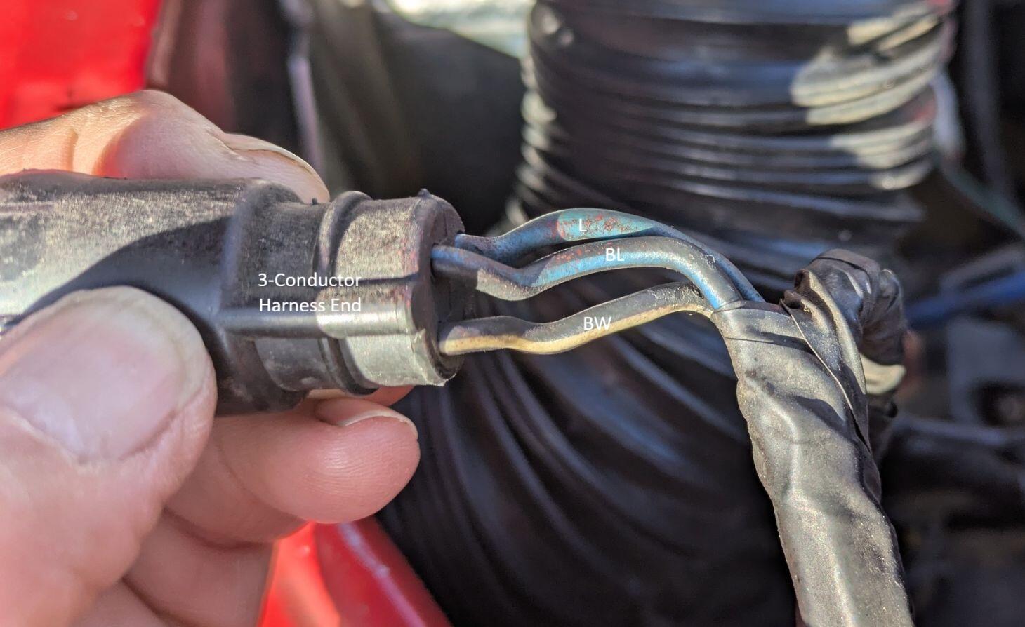
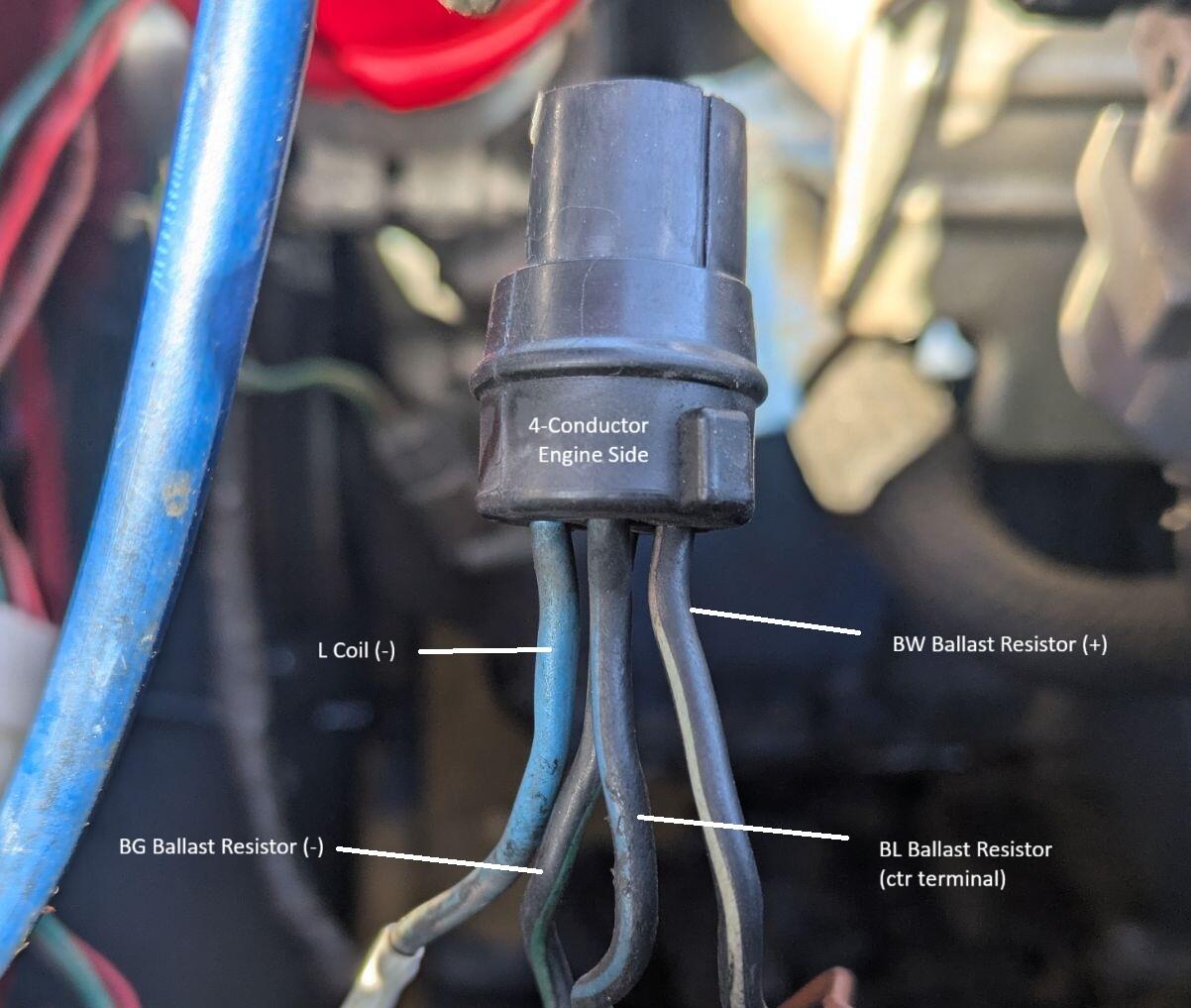
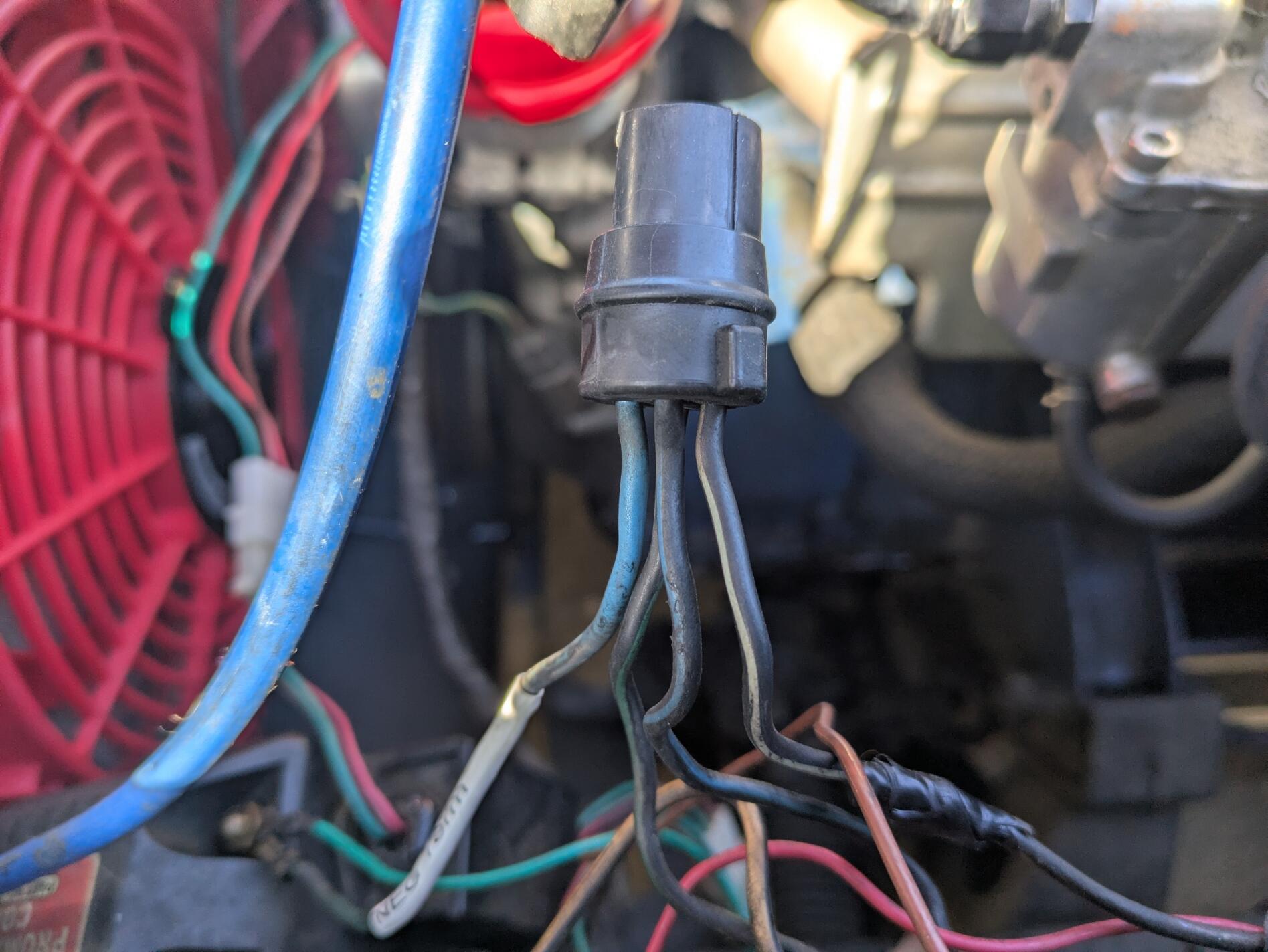
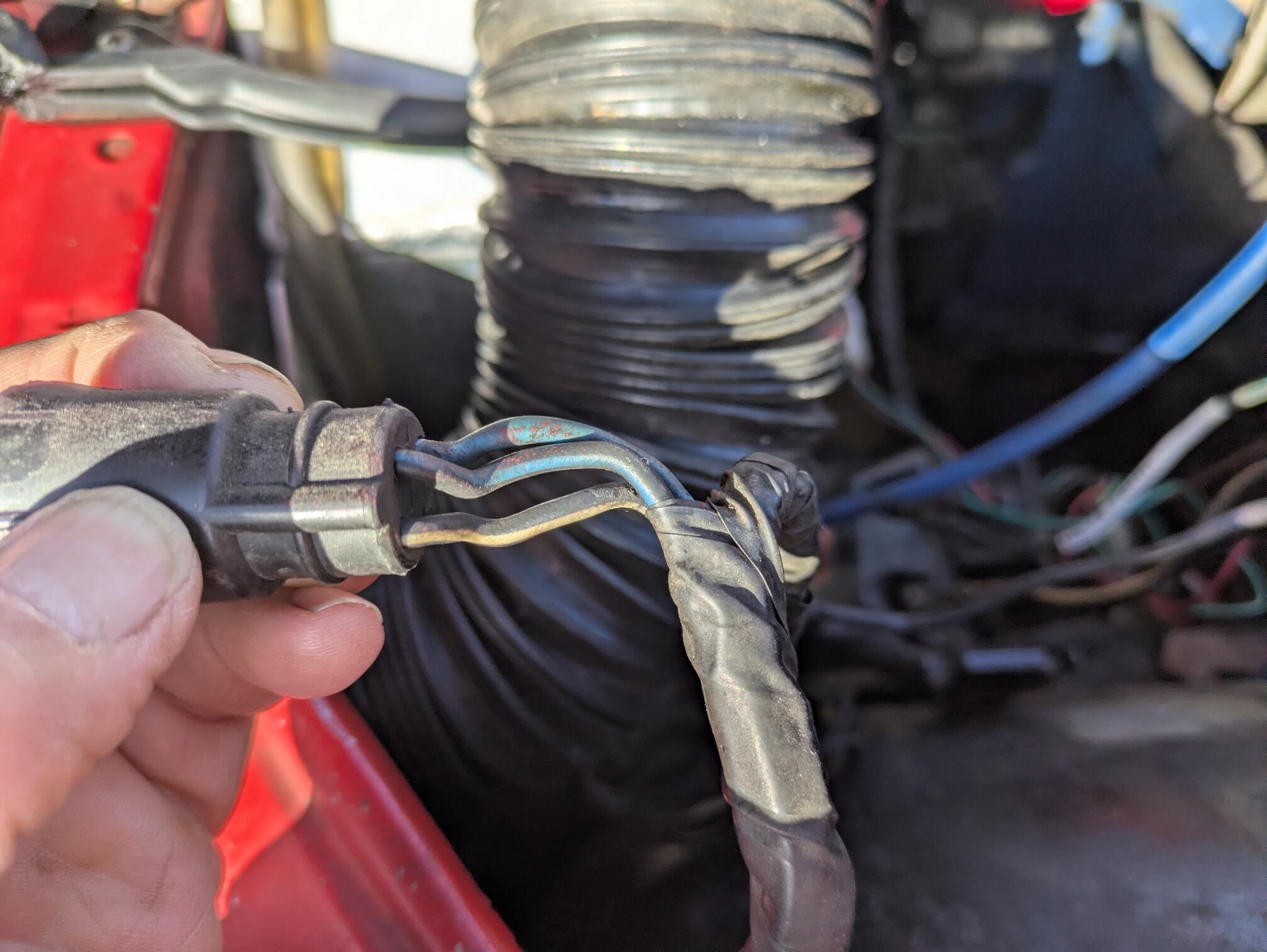
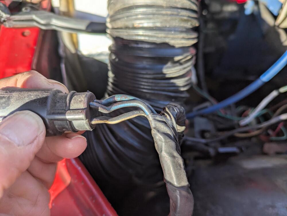
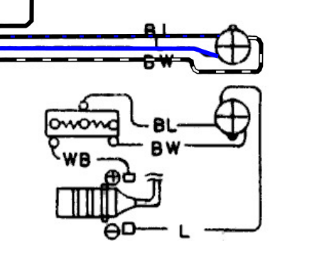
I have a correction to the wiring diagram I provided after I cleaned things up a bit and stripped off some electrical tape. The round connection has 3 wires on the harness side and 4 on the ballast/coil side. I've also found that the BW wire that attaches to the + terminal on the ballast had been cut, then twisted back together and taped. I removed the redundant ballast resistor, and soldered the wire splice so it's making better contact. I'm holding off on the suggestion to disconnect the blue wire since I'm trying to minimize the variables when I make a change. In other words, removing the second ballast resistor and improving the wire splice is enough for now. If the problem persists, I'll disconnect the blue wire. I find it odd that the connector eliminated one of the wires. Note: I have a few blank field books from work lying around that I am finding useful for keeping track of issues and updates to the Z. I wish I thought of this sooner. I also found a source of Brother shrink tube that works in a standard Brother labeler. It's great for labeling wires and holds up better than adhesive labels.
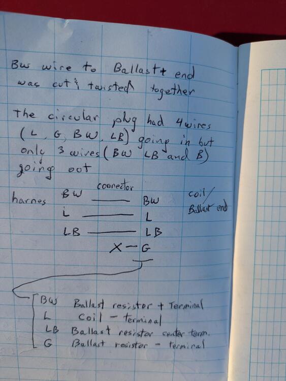
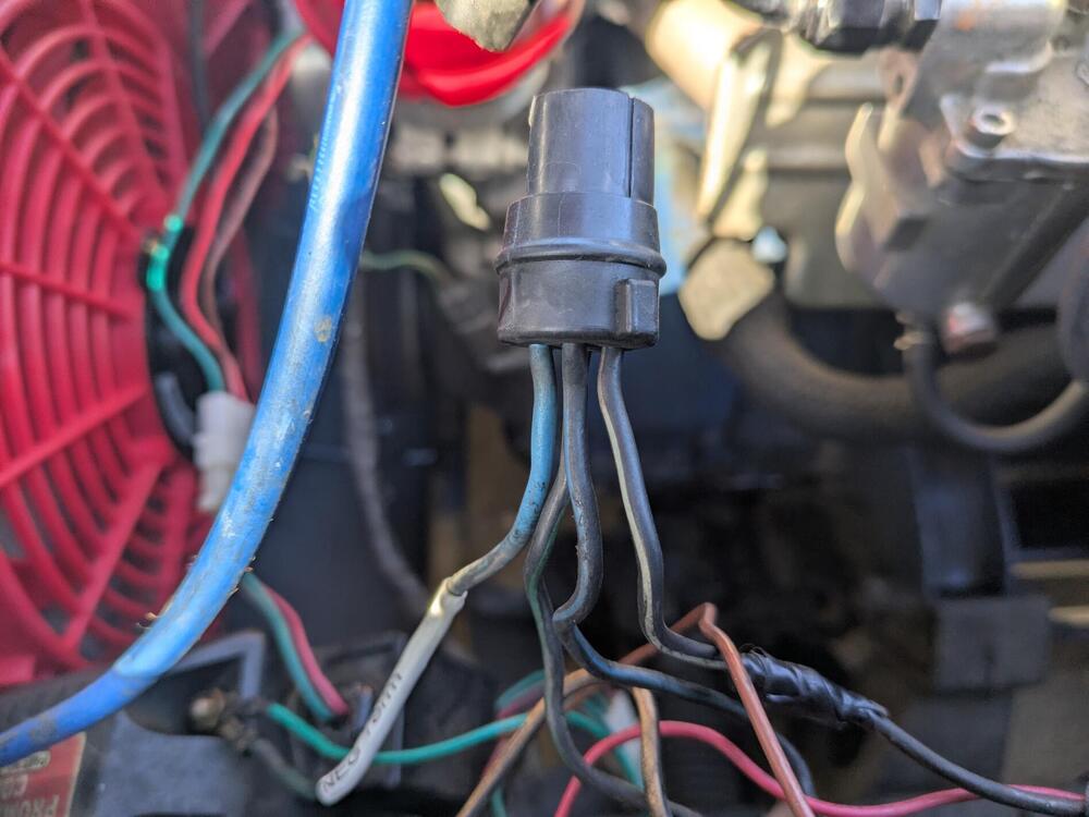
-
The connector is definitely factory and is shown on the wiring diagram. The blue wire splits with one wire going to another resistor and on to the C-4 connector and the second wire that leads to what's labeled as a "full transistor ignitor unit" (FTIU) (whatever that is). The black with blue wire goes to the C-5 connector The black with white wire goes to the emergency switch, the FTIU and the Inter Lock (sic) switch.
-
ZH, yes, the Mallory and the pair of resistors were in there 8 years ago when I purchased the car. This issue with the Unilite has been showing up from time to time so maybe I need to get rid of the second resistor. I'm assuming the resistor with the extra connection in the middle is the one I need to keep. I'll report back after this weekend.
-
I'm unfortunately working out of town for the past few and next few weeks so I have only weekends to address this issue. Mallory wants me next to my car when the give tech support which makes it difficult. Looking at my notes from last weekend I think there is an issue with a ballast resistor once it warms up. If you look at my sketch in a previous post as reference, with the engine running after making sure the Uni-lite drops its voltage to 1.4V when the sensor is blocked, the voltage into the top resistor (R1) is 13V and out of the resistor to ground is 9.5V. The output from R1 goes to the bottom resistor (R2). R2 shows 9.5V in and 5.9V out. After running the car and letting R2 warm up to 120F, the resistance of R2 is 45 ohms. It previously was 1.7 ohms. So if I measured it correctly (the terminals are a bit hard to get a good electrical connection), the resistance of R2 increases as it gets warm which would drop the voltage to the coil. I should of confirmed this but I can do so on Saturday. Could an increase in R2's resistance cause the voltage to drop to the point where it will not permit the ignition, specifically the Uni-lite, to operate?
-
I just re-ran the voltage drop test and its currently showing around 12 volts with the LED not blocked and I think 1.5 volts when the LED is blocked. I tried driving it around for 20 minutes to force it to fail but all I managed to do is annoy my neighbors by making a lot of noise. Why are there two ballast resistors? I'm assuming that I have a total resistance of 3.0 ohms with the three terminal resistor providing 1.3 ohms and some fraction of that on the middle terminal.
-
I have a little more information after some testing. These measurements are all with the car cold. The primary terminals on the coil measures 0.5 ohms The positive terminal to the secondary coil wire terminal is 12.8 K ohms I have two ballast resistors that I'm labeling as R1 and R2 in the diagram. The R1 measures 1.3 ohms while R2 measures 1.7 ohms. Resistor 1 has a third terminal that I didn't test.


-
I'm a couple of hours away from the Z until Saturday so I need to check this list of potential problems this weekend. I was using the following procedure to test the uniLite: chrome-extension://efaidnbmnnnibpcajpcglclefindmkaj/https://documents.holley.com/a605_test.pdf I think the last time it failed with the voltage at 12 V with or without the LED blocked. Once it cooled, the voltage would drop and the car started right up. From an internet search it looks like the Mallory coil should have the following values: primary: 0.6ohms secondary: 11.3kohmf