


Firepower
Free Member
-
Joined
-
Last visited
-
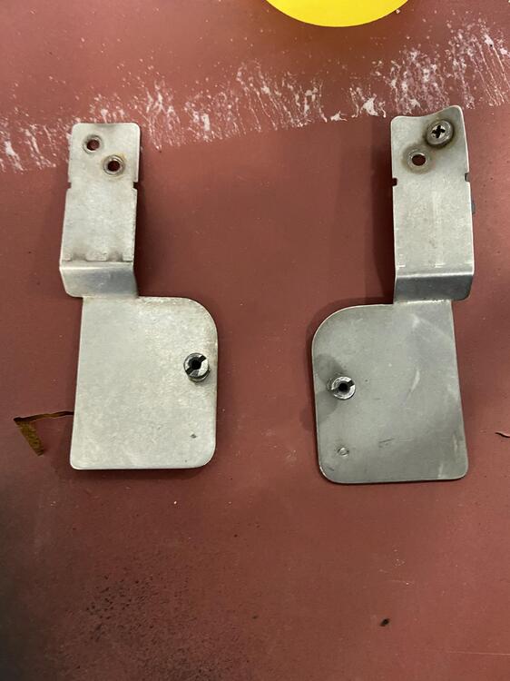
 Thanks, I guess I’ll figure it out from the mounting holes. I’ll post where they go when I figure it out.
 -
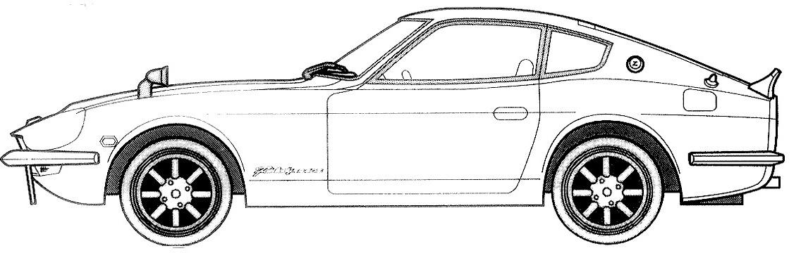
Does anyone know where these go in a ‘72 Datsun 240Z? I’m doing the interior and took out the whole dash to replace with a repro. I just can’t remember what these brackets do. Should have labeled them. Thanks in advance. -Richard
-
No problem. I really liked the tuning capabilities of the 123ignition dizzy for the L6. You can have a tame tune for when you feel calm and want decent milage and a more “spirited tune” that you load for carving canyons or sporting around. You are correct, from memory I have the green/wht, black/white and red wire to the 123/tune+ all on one side of the ballast resistor. Nothing on the other side. The other black/wht wire goes to the coil. So yes, I connected Green/wht, one Black/wht and the Red together. Everything works as it should. Hope this helps.
-
I’m running 123/Tune+ with a non-standard coil and no ballast resistor. This is on a ‘73 240Z. The tach works & exactly matches the 123App. I just jumpered over the ballast resistor (in effect). Actually I put both wires on one side of the ballast resistor as that was easy. I do not know if my tach is different from other earlier ones. I think it’s the “current loop” type. Richard (alienpoker on YouTube)
-
Connectors hang under the car, right next to the middle of the tranny on the passenger side. Comes out of the stock harness on yellow spade connectors. I think it goes up under the ‘dog leg’ panel and connects to the passenger seat pressure sensor. Switch is called ‘STEP LRH’ on the wiring diagrams. But of course you can twist the two switch wires together, and tap into the circuit at the seatbelt buzzer (or light). If that’s what they are. I’ll update later when I get back to electrical connectors.
-
I don’t think this was an automatic car at production. The engine only ever had parts & emission controls that would be on a manual. The “Seat Belt sensor” for passenger looks like the likely source. I didn’t cut the passenger wires, but have disabled the annoying buzzer & light within a year of buying the car. BTW- the power source for the light/buzzer is a useful way to get power when you are in the car AND have the key in the ignition (with the seatbelt unbuckled). If you jumper the seat sensor to be always closed, it’s an interestingly switched ignition +12v source. Maybe a dash camera or a radar sensor? I’ll trace the wire harness back, when I get a chance and post my results here. -R
-
Please help electrical gurus. ‘73 240Z. Found two cut off wires on body near the middle of trans. Both yellow, no stripe codes. I though they could be the reverse lamp switch, but that’s wired up & working. i pulled on the wires and they’re male spade connectors on the side that were cut (not by me obv). Leaving behind two factory female spade connectors in plastic tubes. Any idea? I couldn’t find anything on the wiring diagram that made sense to me. Thanks in advance. -R
-
I think Zed Head / Rill Cosby have valuable points to contribute. Hopefully, that’s why they’re here. We can have different opinions about the same product. And different experiences. IMHO- The OP should have torn down the engine to determine why it failed, before blaming the 123ign unit. Send it back & ask for a refund? Of course, if they offer one and he is unhappy. But I suspect there’s nothing actually wrong with it. To just post a rant saying a unit is crap (without any evidence) is negative. My point is: If The OP can’t be bothered to investigate the problem fully, he can’t just say ‘don’t buy this product’. Better would be ‘I had a bad experience, and this is what I discovered when I dug deeper’.
-
Yes, install dizzy=use timing light. No question. Although a year old thread, I do want to chime in here. Since about the time this thread began, I have been running the (Bluetooth) 123ignition /Tune+ On a 260Z block / heads with twin SUs and SM needles. I also run a hotter coil (oil damped) Bosch Red is also ok. And I’ve bypassed my ballast resistor and rotor resistor myself. Why have extra resistance in your circuits, unless you still use AM radio? Heh, heh. No problems with the engine / timing in over a year of spirited driving. I love to tune it as I choose each day, depending on how I plan to be driving. I have several Curves, like 10 including the ‘Default.123’. I use an ipad and also my iphone. You can tune ‘one the fly’ (just +/- advance, you can’t change or save the curve-yet...). SO City it’s start & stop, so use a good idle maybe 10-12d BTDC at 750rpm -not my default map which as lower idle advance. Cruising the freeway or touring (I want better milage), twisty mountain canyons (lots of advance at high rpm). It’s cool to have variable Timing / vacuum advance curves, without playing with advance weights, or adjusting the position of the dizzy manually to change static advance. Some comments: The setup procedure with the LED light is only good for getting the engine running with the new dizzy. Then run the 123ign centrifugal map with 0 degrees up to 1500rpm in the app and set the engine (with the timing light) to match. I read somewhere that using the LED procedure can actually set 5d TDC static to ‘get the engine started’ easily. I didn’t see this myself, but it brings up the next point. Personally I wouldn’t run the default map and LED timing except to test, and certainly not on the road and under load. Do NOT set up static timing, it screws everything up, and you would have to ADD that to all the values 123ign “sees” in real time and when you add vacuum retard “maps” (which *will* kick in at 1500rpm by default) it gets way too confusing. That is IF you run a vacuum advance line / dizzy (I do)- most with triple DCOEs won’t (or can’t as there isn’t a common plenum). You confuse the123ign and more importantly yourself as to the advance you are running. I did write to Ed Madak, before install and he was very helpful The instructions are incomplete and they expect you have some knowledge. He said: “Hi Richard Setting the app to 0 and the number one cylinder to TDC is preferred as it will show exactly what you have set your timing to. Always confirm using a timing light and synchronize the app with the motor. Hope this helps“ It did help. So you don’t think I’m a fanboy, here are some issues I have experienced and tried to solve: 1. The install instructions are terrible. Read the above and take note, hard lessons learned, you must confirm you have TDC marked correctly on your harmonic balancer. Then use a good timing light, one with dialback if you can. I even made an ‘newbie’s guide’ (ymmv) of my 123ign install & posted it on YouTube: 2. These engines love advance, but personally I don’t exceed 35d advance even at 8000rpm (it’s never driven as a race-car). I also usually RPM limit at 7500, 123ign does random spark cut to keep to that limit. My tach is very accurate and the function works as advertised. I have a ‘hotter cam grind’ and don’t want to bend valves or blow a head gasket. 2. Problems I have had are mostly with the app: i) Sometimes it doesn’t load any curve, and seems to run whatever you save as Default.123 - so make that a gentle map with good idle but one where you will notice a big difference under acceleration (and can’t trash your engine). Butt dyno to the rescue. ii) The ‘map curve’ which does ignition adv/retard from vacuum is difficult to understand at first, I wish it had an option to change it to Hg (mercury), rather than Abs pressure (kP) which the dizzy uses. Yes, you can look up conversion. My default is very gentle, but I have more aggressive maps to run: Default MAP No. Abs Pressure (kP). Degrees Crank 1 0 0 2 29 0 3 30 5 4 45 7 5 85 0 6 100 0 7 200 0 Note: If the Map you’re reading is shown in Degrees camshaft, you need to convert to crank by using a x2 factor. That’s buried in the crap instructions. Crank rotates twice for every single cam rotation. Look at the gear sizes on the timing chain! So you multiply cam x2 to get crank degrees. ii) You can ‘immobilize’ your car in the app, which is a feature I like (I used to run a manual kill switch). It used to work correctly, but now when I go back to settings after disconnecting, the app looks like it’s ready to go. But it isn’t, the engine will die right away. You have to enable, then disable the function. On my New iphone anyway. Not ideal. Iii) The GPS speedo is rubbish compared to other iPhone GPS apps and Speedos on the market. Sometimes it says I’m doing 153 mph (yeah, right) sometimes 25mph and I’m doing a steady 65mph on the freeway. Mostly. But it’s okay as a check, my analog speedo isn’t accurate at some speeds (very low and above 60mph). So it can help ‘fill in the gaps’. iv) As discussed, the cap and rotor aren’t great, and way too expensive. Replace the cap and rotor with a Bosch one. The ‘71 280SL Mercedes and the ‘65 Porsche 911 2.0L base used the same cap, but that’s from memory. Buy products made in Europe, so Germany or Italy. Go to a Porsche site or Imports parts supply. Dizzy cap for 123ignition 123 Tune+ Bosch 1 235 522 060 or Beru VK102 Part Number for the rotor is: Bosch 1 234 332 024 or 1234 332 088 which supersedes the 024 WVE 4R1209 For example, a good quality rotor (Italian made) is also available here for $25 shipped: https://rover.ebay.com/rover/0/0/0?mpre=https%3A%2F%2Fwww.ebay.com%2Fulk%2Fitm%2F333529359496 I bought a Bosch cap NOS (in original box) on eBay for around $16, in fact I got two- and was happy. If I wasn’t (cracked or used) I would have sent it back for a refund under eBay/PayPal policy. Finally, the rotor should not come with a resistor, I’ve modified mine by soldering in a piece of ‘house wiring’ gauge copper wire No problems at all, but you may need to file the top of the wire flatter to have good clearance. Good practice would be to encase the copper wire run in epoxy, so you don’t get unwanted spark jumps. Especially if you run MSD 6AL and a hotter coil. v) No data logging. A huge disappointment, or has to track the data, why not be able to save a ‘pull’ to look back at what the dizzy (and the car) did. Fix this! That’s it. My experience has been quite good. These are machines. Cars and engines go wrong. You all know that. There’s probably more I could say, but I hadn’t intended to write a book when I started. If you’re reading this far, you have the benefit of what I’ve discovered. I like the 123i Tune+ dizzy and plan to use another one soon- maybe just the USB one as it could have a single standard tune. This is on a built stroker 3.xL with triple webber DCOEs, hot cam, etc. I’m not scared that if set up correctly, it won’t detonate your engine. It should default to a map that ‘still makes sense’ if it goes out. BTW the holes 4&5 on the L6 are more prone to failure than the others. Don’t ask me how I know...
-
Yes. It’s probably knockoff junk. I found this thread which has pretty accurate wiring diagram which I can work from. see: 240Z-msd6al-8920-tach-adapter I think the first trick is to bypass the ballast resistor, which I have already done. It’s easiest to just leave it there and move one of the wires so the black/wht and black/grn are connected together. Or you could put a jumper wire between the two terminals For the 8920 tach adapter: Black Wire is Gnd Red wire connects to the old (+) wire from the coil. (black/wht on a 240Z) White wire to Grey wire on the MSD6AL (tach signal) Violet wire is unused As the PCE387.1002 has R,Bl,Or,Grn My best guess from research is to hook it up the same way for Red & Blk and use the Green wire to the Grey wire on the MSD6AL. Looks like Procomp use Green as their “tach signal“ color. The Orange wire is unused. Once it all works, I’ll document exactly what I did and post it. Probably by buying the MSD 8920 first and sending the PCE (now Speedmaster) junk back. Be warned, buy the MSD6AL and MSD accessories, not clone parts. It’s not worth your time to save a few $. I’ve since read lots of reviews saying the ProcompElectronics.com (Speedmaster79.com) stuff falls apart or stops working Edit: I have now sent it back and am awaiting a refund. Not worth damaging it and having to eat the cost. Also for the difference in price it wasn’t worth the hassle. I will not be doing business with Procomp/Speedmaster again. I have ordered the actual MSD8920 from Jegs. At least if there is any issue I’m dealing with the same company (MSD) for both the 6AL and the 8920.
-
Firepower changed their profile photo
-
Stock 240Z. Will be adding: MSD6AL. 123ignition Tune+ and MSD6290 tach adapter except as I said I have the PCE2030 (p/n PCE387.1002) which is an ‘8920 clone’. I can add them in stages. I’m sure I can get the first two to work fairly easily. But need advice on the 3rd -getting a stock tach to work with the above two changes. Or should I send it back and get the proper MSD8920? Any advice will be gratefully received. -Richard
-
Yeah, well I smoked a Tech once when ghe Alternator bridge burnt out on a ‘73. So I’m not in a hurry to try wiring it up without a tach adapter. I understand it’s current rater than voltage based.
-
Hi - I understand this is an old thread, but there’s lots of relevant & useful info here. So I’ll post here. as OP states, I think you need the MSD8920 to work with the early stock tachs, mine’s a ‘73 240Z. My understanding is it’s a ‘current loop’ tach so one side (black/wh wire) goes to the pos + on the coil. The other side (grn) used to go to the ballast resistor (which I removed - so just straight to keyed ignition. That is stock and works, is stable and very accurate. I’m installing an MSD6AL to my car, and bought that and a PCE2030 (p/n PCE387.1002) which is an 8920 type tach adapter. No instructions, just the unit. So far so good- but the wire colors are different from the MSD 8920 and when I contacted the supplier, they just sent me to the MSD diagrams and said it was ‘the same’. But the wire colors are not. MSD8920 has Red, Black, Violet & White. I have 4 wires on the PCE tach adapter I bought: Red, Black, Green, Orange I think I end up with the Red wire on the Tach adapter at the Grn wire of the tach, and so on to switched ignition. That’s all I’m sure of. There is No white wire on the “8920” unit I bought. Anyone have a wiring diagram or can help? Nothing but orange/black from the MSD6AL will end up running to the coil, so the existing tach black/wh wire has to move. Thanks.
-
Use a smaller battery if you have that. A 12v motorcycle or maybe electric scooter battery with both the replacement gauge and temp sender off the car.
-
It looks to be M16 x 1.75 I can measure the 1.75 thread pitch, but I don't have a bolt that big to check it fits. Looks like an M16 as a 16mm deep socket takes it off, and the threads are nearly the same size width as the ‘head’ But as I said, just buy one, it’s like $10 Rockauto-temperature-sender-1T1181 It fits all these Nissan cars: Nissan cars & trucks: 200SX 1977-1983 240Z 1970-1973 260Z 1974 280Z 1975-1978 280ZX 1979-1983 B210 1974-1978 F10 1976-1978 Maxima 1982-1983 Pick Up 1968-1985 Pulsar 1986 Sentra 1982 Stanza 1982, 1984-1986 210 1979-1982 310 1979-1982 510 1968-1973, 1978-1981 610 1973-1976 710 1974-1977 810 1977-1981 1000 Series 1968-1973 2000 Series 1968-1970


